EP3402031A1 - Agencement de circuit et système d'alimentation - Google Patents
Agencement de circuit et système d'alimentation Download PDFInfo
- Publication number
- EP3402031A1 EP3402031A1 EP17169961.4A EP17169961A EP3402031A1 EP 3402031 A1 EP3402031 A1 EP 3402031A1 EP 17169961 A EP17169961 A EP 17169961A EP 3402031 A1 EP3402031 A1 EP 3402031A1
- Authority
- EP
- European Patent Office
- Prior art keywords
- battery
- terminal
- circuit arrangement
- electric machine
- line
- Prior art date
- Legal status (The legal status is an assumption and is not a legal conclusion. Google has not performed a legal analysis and makes no representation as to the accuracy of the status listed.)
- Pending
Links
Images







Classifications
-
- H—ELECTRICITY
- H02—GENERATION; CONVERSION OR DISTRIBUTION OF ELECTRIC POWER
- H02J—ELECTRIC POWER NETWORKS; CIRCUIT ARRANGEMENTS OR SYSTEMS FOR SUPPLYING OR DISTRIBUTING ELECTRIC POWER; SYSTEMS FOR STORING ELECTRIC ENERGY
- H02J7/00—Circuit arrangements for charging or discharging batteries or for supplying loads from batteries
-
- B—PERFORMING OPERATIONS; TRANSPORTING
- B60—VEHICLES IN GENERAL
- B60L—PROPULSION OF ELECTRICALLY-PROPELLED VEHICLES; SUPPLYING ELECTRIC POWER FOR AUXILIARY EQUIPMENT OF ELECTRICALLY-PROPELLED VEHICLES; ELECTRODYNAMIC BRAKE SYSTEMS FOR VEHICLES IN GENERAL; MAGNETIC SUSPENSION OR LEVITATION FOR VEHICLES; MONITORING OPERATING VARIABLES OF ELECTRICALLY-PROPELLED VEHICLES; ELECTRIC SAFETY DEVICES FOR ELECTRICALLY-PROPELLED VEHICLES
- B60L50/00—Electric propulsion with power supplied within the vehicle
- B60L50/50—Electric propulsion with power supplied within the vehicle using propulsion power supplied by batteries or fuel cells
- B60L50/60—Electric propulsion with power supplied within the vehicle using propulsion power supplied by batteries or fuel cells using power supplied by batteries
- B60L50/66—Arrangements of batteries
-
- B—PERFORMING OPERATIONS; TRANSPORTING
- B60—VEHICLES IN GENERAL
- B60L—PROPULSION OF ELECTRICALLY-PROPELLED VEHICLES; SUPPLYING ELECTRIC POWER FOR AUXILIARY EQUIPMENT OF ELECTRICALLY-PROPELLED VEHICLES; ELECTRODYNAMIC BRAKE SYSTEMS FOR VEHICLES IN GENERAL; MAGNETIC SUSPENSION OR LEVITATION FOR VEHICLES; MONITORING OPERATING VARIABLES OF ELECTRICALLY-PROPELLED VEHICLES; ELECTRIC SAFETY DEVICES FOR ELECTRICALLY-PROPELLED VEHICLES
- B60L1/00—Supplying electric power to auxiliary equipment of vehicles
-
- B—PERFORMING OPERATIONS; TRANSPORTING
- B60—VEHICLES IN GENERAL
- B60L—PROPULSION OF ELECTRICALLY-PROPELLED VEHICLES; SUPPLYING ELECTRIC POWER FOR AUXILIARY EQUIPMENT OF ELECTRICALLY-PROPELLED VEHICLES; ELECTRODYNAMIC BRAKE SYSTEMS FOR VEHICLES IN GENERAL; MAGNETIC SUSPENSION OR LEVITATION FOR VEHICLES; MONITORING OPERATING VARIABLES OF ELECTRICALLY-PROPELLED VEHICLES; ELECTRIC SAFETY DEVICES FOR ELECTRICALLY-PROPELLED VEHICLES
- B60L15/00—Methods, circuits, or devices for controlling the traction-motor speed of electrically-propelled vehicles
- B60L15/007—Physical arrangements or structures of drive train converters specially adapted for the propulsion motors of electric vehicles
-
- B—PERFORMING OPERATIONS; TRANSPORTING
- B60—VEHICLES IN GENERAL
- B60L—PROPULSION OF ELECTRICALLY-PROPELLED VEHICLES; SUPPLYING ELECTRIC POWER FOR AUXILIARY EQUIPMENT OF ELECTRICALLY-PROPELLED VEHICLES; ELECTRODYNAMIC BRAKE SYSTEMS FOR VEHICLES IN GENERAL; MAGNETIC SUSPENSION OR LEVITATION FOR VEHICLES; MONITORING OPERATING VARIABLES OF ELECTRICALLY-PROPELLED VEHICLES; ELECTRIC SAFETY DEVICES FOR ELECTRICALLY-PROPELLED VEHICLES
- B60L58/00—Methods or circuit arrangements for monitoring or controlling batteries or fuel cells, specially adapted for electric vehicles
- B60L58/10—Methods or circuit arrangements for monitoring or controlling batteries or fuel cells, specially adapted for electric vehicles for monitoring or controlling batteries
-
- B—PERFORMING OPERATIONS; TRANSPORTING
- B60—VEHICLES IN GENERAL
- B60L—PROPULSION OF ELECTRICALLY-PROPELLED VEHICLES; SUPPLYING ELECTRIC POWER FOR AUXILIARY EQUIPMENT OF ELECTRICALLY-PROPELLED VEHICLES; ELECTRODYNAMIC BRAKE SYSTEMS FOR VEHICLES IN GENERAL; MAGNETIC SUSPENSION OR LEVITATION FOR VEHICLES; MONITORING OPERATING VARIABLES OF ELECTRICALLY-PROPELLED VEHICLES; ELECTRIC SAFETY DEVICES FOR ELECTRICALLY-PROPELLED VEHICLES
- B60L58/00—Methods or circuit arrangements for monitoring or controlling batteries or fuel cells, specially adapted for electric vehicles
- B60L58/10—Methods or circuit arrangements for monitoring or controlling batteries or fuel cells, specially adapted for electric vehicles for monitoring or controlling batteries
- B60L58/18—Methods or circuit arrangements for monitoring or controlling batteries or fuel cells, specially adapted for electric vehicles for monitoring or controlling batteries of two or more battery modules
- B60L58/21—Methods or circuit arrangements for monitoring or controlling batteries or fuel cells, specially adapted for electric vehicles for monitoring or controlling batteries of two or more battery modules having the same nominal voltage
-
- H—ELECTRICITY
- H02—GENERATION; CONVERSION OR DISTRIBUTION OF ELECTRIC POWER
- H02J—ELECTRIC POWER NETWORKS; CIRCUIT ARRANGEMENTS OR SYSTEMS FOR SUPPLYING OR DISTRIBUTING ELECTRIC POWER; SYSTEMS FOR STORING ELECTRIC ENERGY
- H02J7/00—Circuit arrangements for charging or discharging batteries or for supplying loads from batteries
- H02J7/50—Circuit arrangements for charging or discharging batteries or for supplying loads from batteries acting upon multiple batteries simultaneously or sequentially
- H02J7/575—Parallel/serial switching of connection of batteries to charge or load circuit
-
- B—PERFORMING OPERATIONS; TRANSPORTING
- B60—VEHICLES IN GENERAL
- B60L—PROPULSION OF ELECTRICALLY-PROPELLED VEHICLES; SUPPLYING ELECTRIC POWER FOR AUXILIARY EQUIPMENT OF ELECTRICALLY-PROPELLED VEHICLES; ELECTRODYNAMIC BRAKE SYSTEMS FOR VEHICLES IN GENERAL; MAGNETIC SUSPENSION OR LEVITATION FOR VEHICLES; MONITORING OPERATING VARIABLES OF ELECTRICALLY-PROPELLED VEHICLES; ELECTRIC SAFETY DEVICES FOR ELECTRICALLY-PROPELLED VEHICLES
- B60L2200/00—Type of vehicles
- B60L2200/10—Air crafts
-
- B—PERFORMING OPERATIONS; TRANSPORTING
- B60—VEHICLES IN GENERAL
- B60L—PROPULSION OF ELECTRICALLY-PROPELLED VEHICLES; SUPPLYING ELECTRIC POWER FOR AUXILIARY EQUIPMENT OF ELECTRICALLY-PROPELLED VEHICLES; ELECTRODYNAMIC BRAKE SYSTEMS FOR VEHICLES IN GENERAL; MAGNETIC SUSPENSION OR LEVITATION FOR VEHICLES; MONITORING OPERATING VARIABLES OF ELECTRICALLY-PROPELLED VEHICLES; ELECTRIC SAFETY DEVICES FOR ELECTRICALLY-PROPELLED VEHICLES
- B60L2200/00—Type of vehicles
- B60L2200/32—Waterborne vessels
-
- B—PERFORMING OPERATIONS; TRANSPORTING
- B60—VEHICLES IN GENERAL
- B60R—VEHICLES, VEHICLE FITTINGS, OR VEHICLE PARTS, NOT OTHERWISE PROVIDED FOR
- B60R16/00—Electric or fluid circuits specially adapted for vehicles and not otherwise provided for; Arrangement of elements of electric or fluid circuits specially adapted for vehicles and not otherwise provided for
- B60R16/02—Electric or fluid circuits specially adapted for vehicles and not otherwise provided for; Arrangement of elements of electric or fluid circuits specially adapted for vehicles and not otherwise provided for electric constitutive elements
- B60R16/03—Electric or fluid circuits specially adapted for vehicles and not otherwise provided for; Arrangement of elements of electric or fluid circuits specially adapted for vehicles and not otherwise provided for electric constitutive elements for supply of electrical power to vehicle subsystems or for
- B60R16/033—Electric or fluid circuits specially adapted for vehicles and not otherwise provided for; Arrangement of elements of electric or fluid circuits specially adapted for vehicles and not otherwise provided for electric constitutive elements for supply of electrical power to vehicle subsystems or for characterised by the use of electrical cells or batteries
-
- B—PERFORMING OPERATIONS; TRANSPORTING
- B60—VEHICLES IN GENERAL
- B60Y—INDEXING SCHEME RELATING TO ASPECTS CROSS-CUTTING VEHICLE TECHNOLOGY
- B60Y2200/00—Type of vehicle
- B60Y2200/90—Vehicles comprising electric prime movers
- B60Y2200/91—Electric vehicles
-
- B—PERFORMING OPERATIONS; TRANSPORTING
- B60—VEHICLES IN GENERAL
- B60Y—INDEXING SCHEME RELATING TO ASPECTS CROSS-CUTTING VEHICLE TECHNOLOGY
- B60Y2400/00—Special features of vehicle units
- B60Y2400/11—Electric energy storages
- B60Y2400/112—Batteries
-
- H—ELECTRICITY
- H02—GENERATION; CONVERSION OR DISTRIBUTION OF ELECTRIC POWER
- H02J—ELECTRIC POWER NETWORKS; CIRCUIT ARRANGEMENTS OR SYSTEMS FOR SUPPLYING OR DISTRIBUTING ELECTRIC POWER; SYSTEMS FOR STORING ELECTRIC ENERGY
- H02J2105/00—Networks for supplying or distributing electric power characterised by their spatial reach or by the load
- H02J2105/30—Networks for supplying or distributing electric power characterised by their spatial reach or by the load the load networks being external to vehicles, i.e. exchanging power with vehicles
- H02J2105/33—Networks for supplying or distributing electric power characterised by their spatial reach or by the load the load networks being external to vehicles, i.e. exchanging power with vehicles exchanging power with road vehicles
-
- Y—GENERAL TAGGING OF NEW TECHNOLOGICAL DEVELOPMENTS; GENERAL TAGGING OF CROSS-SECTIONAL TECHNOLOGIES SPANNING OVER SEVERAL SECTIONS OF THE IPC; TECHNICAL SUBJECTS COVERED BY FORMER USPC CROSS-REFERENCE ART COLLECTIONS [XRACs] AND DIGESTS
- Y02—TECHNOLOGIES OR APPLICATIONS FOR MITIGATION OR ADAPTATION AGAINST CLIMATE CHANGE
- Y02T—CLIMATE CHANGE MITIGATION TECHNOLOGIES RELATED TO TRANSPORTATION
- Y02T10/00—Road transport of goods or passengers
- Y02T10/60—Other road transportation technologies with climate change mitigation effect
- Y02T10/64—Electric machine technologies in electromobility
-
- Y—GENERAL TAGGING OF NEW TECHNOLOGICAL DEVELOPMENTS; GENERAL TAGGING OF CROSS-SECTIONAL TECHNOLOGIES SPANNING OVER SEVERAL SECTIONS OF THE IPC; TECHNICAL SUBJECTS COVERED BY FORMER USPC CROSS-REFERENCE ART COLLECTIONS [XRACs] AND DIGESTS
- Y02—TECHNOLOGIES OR APPLICATIONS FOR MITIGATION OR ADAPTATION AGAINST CLIMATE CHANGE
- Y02T—CLIMATE CHANGE MITIGATION TECHNOLOGIES RELATED TO TRANSPORTATION
- Y02T10/00—Road transport of goods or passengers
- Y02T10/60—Other road transportation technologies with climate change mitigation effect
- Y02T10/70—Energy storage systems for electromobility, e.g. batteries
Definitions
- the present application relates to a circuit arrangement for supplying an electric vehicle with power and to a power system for an electric vehicle.
- Electric vehicles with an electric machine or an electric motor require a battery with a large capacity in order to enable traveling over large distances.
- a battery with a large capacity In order to achieve a large capacity of the battery it is common to connect a plurality of battery cells with a small capacity, as for example lithium ion batteries.
- the battery voltage can amount to several hundreds of volts. For these high voltages a special isolation of the battery and other safety precautions are required.
- a further objective is to provide a circuit arrangement for supplying an electric vehicle with power and a power system which can supply both the electric machine and the power net of the electric vehicle with power.
- the circuit arrangement for supplying an electric vehicle with power, comprises a battery with a first terminal and a second terminal.
- the first and the second terminal can be electrical contacts where the battery can be electrically contacted and where a load can be connected.
- the battery can comprise a plurality of battery cells that are connected with each other.
- the battery cells can be for example lithium ion batteries.
- the electric vehicle can be any craft that can move on ground, in the air or on water.
- the electric vehicle can be a car, an airplane or a boat.
- the circuit arrangement further comprises a reference potential terminal directly connected to the second terminal of the battery. This means, the battery and the reference potential terminal are electrically connected. The battery voltage is given relative to the reference potential.
- the circuit arrangement further comprises a first output that is coupled to the first terminal of the battery via a first switch and that is configured to be connected to an electric machine of the electric vehicle.
- the first output can be an electrical contact or an electrical terminal.
- the first output is electrically coupled to the first terminal of the battery via the first switch.
- the first terminal of the battery can be directly connected with the first switch and the first switch can be directly connected with the first output. With the first switch the connection between the battery and the electric machine can be activated and deactivated.
- the electric machine of the electric vehicle can be for example an electric motor.
- the movement of the electric vehicle can be driven by the electric machine and the electric machine is the main engine for traction of the electric vehicle.
- the electric machine comprises several electric machines or several electric motors.
- the electric machine can comprise an electric machine for a front axle and a back axle of an electric vehicle, respectively.
- the electric machine comprises four electric machines or four electric motors.
- That the first output is configured to be connected to an electric machine of the electric vehicle means that the first output can be electrically connected with the electric machine. If for example the electric machine comprises an electrical contact the first output can be electrically connected with the electrical contact of the electric machine. Preferably, the first output is configured to be connected to the electric machine in such a way that the electric machine can be supplied with power by the battery.
- the circuit arrangement further comprises a second output that is coupled to the first terminal of the battery and that is configured to be connected to a power net of the electric vehicle.
- the second output can be an electrical contact or an electrical terminal.
- the second output is electrically coupled to the first terminal of the battery.
- the power net of the electric vehicle is configured to supply other devices in the electric vehicle than the electric machine with power.
- the other devices in the electric vehicle can be for example the radio, loudspeakers, a navigation system, lights or windscreen wipers.
- the second output can be directly coupled to the first terminal of the battery. It is also possible that the second output is coupled to the first terminal of the battery via a second switch.
- the first terminal of the battery can be directly connected with the second switch and the second switch can be directly connected with the second output.
- the battery is configured to supply both the electric machine and the power net of the electric vehicle with power. Consequently, only one battery is required for the electric vehicle.
- the electric machine and the power net are supplied with the same voltage level by the battery.
- the electric machine and the power net are operated at the same voltage level.
- the same voltage level in this case means that it is approximately the same voltage level.
- the exact voltage level at the electrical contacts of the electric machine and the power net can slightly differ from the battery voltage because of losses in the circuit arrangement.
- the voltage level at the electrical contacts of the electric machine and the power net can also slightly differ from the battery voltage because of losses at switches or other components of the circuit arrangement.
- the power net comprises a sub power net which is operated at a voltage which is different from the battery voltage.
- a part of the power net can be operated at a voltage which is lower than the battery voltage.
- the sub power net can for example be operated at 12 V.
- the electric vehicle is at least one of:
- the battery voltage which can be tapped between the first terminal and the second terminal of the battery is at most 60 V.
- the battery voltage is at least 6 V.
- the battery voltage is a direct current (DC) voltage. For this voltage range it is possible that the battery is operated at separated extra low voltage and that it is compliant with standards defining the separated extra low voltage.
- the rated battery voltage amounts to 48 V.
- a small battery voltage enables that the electric machine and the power net can both be supplied with power by the battery.
- the second output is directly and permanently coupled to the first terminal of the battery. This means, the second output is not coupled to the first terminal via a second switch but the second output is directly coupled to the first terminal. In this case the power net of the electric machine is permanently coupled to the battery.
- the second output is coupled to the first terminal of the battery via a second switch.
- the first terminal of the battery can be directly connected with the second switch and the second switch can be directly connected with the second output. With the second switch the connection between the battery and the power net can be activated and deactivated.
- the electric machine to which the first output is configured to be connected to is the traction engine of the electric vehicle.
- the movement of the electric vehicle is driven by the electric machine and the electric machine is the main engine for traction of the vehicle.
- the electric machine is the only traction engine of the electric vehicle and the electric vehicle does not comprise another traction engine as for example a petrol engine.
- the first switch comprises at least two sub-switches arranged in at least two parallel lines where the parallel lines are connected with each other by an inductive connection which comprises at least one inductivity.
- line refers to an electrical connection. Alternative expressions for "line” are line section, chain, string or strand.
- the at least two sub-switches can be mechanical or electro-mechanical switches or semiconductor switches.
- the at least two sub-switches are connected with each other in parallel. This means at least two lines comprising each a sub-switch are connected with each other in parallel.
- the at least two lines are connected with each other by an inductive connection.
- the inductive connection can be an electrical connection between the at least two lines.
- the inductive connection comprises at least one inductivity means that the at least two lines are connected with each other via the inductivity.
- the inductivity can comprise a first electrical contact which is connected to one of the at least two lines.
- the inductivity further can comprise a second electrical contact which is connected to another one of the at least two lines.
- the inductivity comprises an inductor as for example a coil.
- the at least two sub-switches of the first switch are usually opened with small time delays. In order to avoid that the current from the battery towards the first output only flows through the sub-switch which is opened at last the inductivities allow compensation currents between the sub- switches and avoid rapidly rising currents in the first switch.
- the first terminal and the second terminal of the battery are coplanar or coaxial.
- the first and the second terminal can for example be arranged at an outer surface of the battery.
- the first and the second terminal can comprise the same or a similar shape.
- the first terminal and the second terminal are coplanar or coaxial in order to reduce the extent of the magnetic field induced by the current flowing through the terminals.
- the first terminal and/or the second terminal of the battery comprise at least two contacts, respectively.
- the at least two contacts of the first and/or the second terminal can be arranged next to each other or on top of each other. It is also possible that the at least two contacts of the first and/or the second terminal are arranged at different side surfaces of the battery. As the battery voltage is small, the currents at the first and the second terminal can be high. Therefore, it is advantageous to distribute the current over several electrical contacts.
- the first terminal and the second terminal of the battery are arranged coaxial. Also in this way the extent of the magnetic field induced by the current flowing through the terminals is reduced.
- the first terminal and/or the second terminal of the battery are arranged as plugs. In another embodiment of the circuit arrangement, the first terminal and/or the second terminal of the battery are arranged as sockets.
- the battery comprises at least one line of battery cells, where a first group comprises a plurality of battery cells connected to each other in parallel, a second group comprises a plurality of battery cells connected to each other in parallel, and the first group and the second group are connected with each other in series forming the line of battery cells.
- the battery cells can be for example lithium ion batteries with rated cell voltages between 3 and 4 V.
- the battery cells each comprise electrical contacts via which they can be electrically contacted. This means, in the first group and in the second group the battery cells are connected in parallel in an electrical circuit, respectively. The first group and the second group are connected in series in an electrical circuit.
- line refers to a plurality of battery cells electrically connected to each other. Each line comprises at least a first group and a second group that are connected with each other in series. Alternative expressions for "line” are line section, chain, string or strand.
- further groups of battery cells are connected in series with the first group and the second group. Also the further groups comprise a plurality of battery cells connected to each other in parallel.
- the battery cells are arranged in such a way that a small battery voltage is enabled.
- a small battery voltage can be for example a voltage which is equal to or smaller than 60 V.
- the number of battery cells connected with each other in the first group and in the second group, respectively, are chosen in such a way that the capacity of the battery is as high as required for an electric vehicle.
- the number of groups connected to each other in series is kept small enough such that the battery voltage does not exceed a desired value.
- the battery is configured in such a way that the battery voltage is small. This means, the battery voltage can be for example below a set maximum value.
- the line is connected to at least one further line in parallel, where the further line comprises the same features as the line, and a fuse is connected to a circuit node of the line and to a circuit node of the further line.
- the further line comprises at least one first group and at least one second group of battery cells. The line and the at least one further line are connected with each other in parallel in an electrical circuit.
- the capacity of the battery is increased. Consequently, the number of groups connected in series to each other in each line can be kept small enough such that the battery voltage does not exceed a desired value and at the same time the capacity of the battery is as high as required for an electric vehicle.
- line currents Due to slight differences between the battery cells the currents in the different lines, referred to as line currents, can differ from each other. Consequently, the battery cells in a line with a higher line current are discharged more than battery cells in a line with a smaller line current. This means, the battery cells that are discharged more are degrading and aging faster than the other battery cells. Furthermore, it is possible that compensation currents arise if the power consumed by for example the electric machine or another load changes with time. By employing the fuse the different line currents can be regulated such that all line currents are the same or very similar. Furthermore, if for example a battery cell in a line is defective a high line current can arise in the line. With the fuse it is avoided that the high line current also flows through further lines.
- the fuse is a positive temperature coefficient thermistor.
- the resistance of the positive temperature coefficient thermistor increases such that the high line current cannot flow from the line to the further line. If the line current decreases again the positive temperature coefficient thermistor cools down again and the resistance decreases.
- the battery comprises at least two battery modules.
- the battery cells of the battery are distributed over the at least two battery modules. Every battery module comprises a plurality of battery cells.
- the battery modules can be configured to be exchanged separately from each other. This means, at least some of the battery modules can be removed from the electric vehicle and be replaced by for example charged battery modules. For example, battery modules that are arranged in easily accessible places of the electric vehicle as the trunk can be exchanged. In this way, a driver or a user of the electric vehicle does not have to wait until all battery modules are recharged before continuing to drive but the driver or the user can exchange some battery modules which takes less time than recharging all battery modules.
- the at least two battery modules are configured to be electrically coupled to the electric machine of the electric vehicle.
- the electric machine is employed to equalize the line currents of the different lines of the battery. If an electric machine comprises different electrical phases each line is electrically connected to one or more electrical phases. By supplying the electrical phases with different DC currents the line currents can be regulated and equalized. As the electric machine is controlled by AC currents of the different electrical phases the regulation of the line currents can take place both when the electric machine is operated and when it is not operated since the line currents are regulated only by DC currents. Alternatively, it is possible to employ the electric machine partially in motor mode and partially in generator mode for regulating the line currents.
- the at least two battery modules are arranged in parallel and each battery module is assigned a respective switch to activate and/or deactivate the respective battery module.
- the switch can be for example a DC/DC converter, an electro mechanical switch, a semiconductor switch or an electrical switch.
- the battery modules can be arranged in different places of the electric vehicle and the risk of a local damage of the battery is reduced as a damaged battery module can be disconnected from the other battery modules by the respective switch.
- the power system comprises an embodiment of the circuit arrangement as described above.
- the power system further comprises an electric machine and a power net, where the first output is electrically coupled to the electric machine and the second output is electrically coupled to the power net.
- the battery is configured to supply both the electric machine and the power net of the electric vehicle with power. Consequently, only one battery is required for the electric vehicle.
- the power system can be comprised by an electric vehicle.
- the power system is arranged to supply the electric vehicle with power, to enable movement of the electric vehicle and to enable the operation of the devices of the power net.
- the battery voltage is at least 6 V and at most 60 V.
- the rated battery voltage amounts to 48 V.
- less isolation and less safety precautions are required for these small battery voltages.
- a small battery voltage enables that the electric machine and the power net can both be supplied with power by the battery of the power system.
- the electric machine and the power net are supplied with the same voltage level by the battery.
- the electric machine and the power net are operated at the same voltage level.
- the same voltage level in this case means that it is approximately the same voltage level.
- the exact voltage level at the electrical contacts of the electric machine and the power net can slightly differ from the battery voltage because of losses in the circuit arrangement.
- the voltage level at the electrical contacts of the electric machine and the power net can also slightly differ from the battery voltage because of losses at switches or other components of the circuit arrangement.
- the power net comprises a sub power net which is operated at a voltage which is different from the battery voltage.
- a part of the power net can be operated at a voltage which is lower than the battery voltage.
- the sub power net can for example be operated at 12 V.
- the electric machine is only powered by the battery. This means, the movement of the electric vehicle is driven by the electric machine and the electric machine is the main engine for traction of the vehicle.
- the power system and the electric vehicle do not comprise another source of power for the electric machine than the battery.
- the electric machine is the only traction engine of the electric vehicle and the electric vehicle does not comprise another traction engine as for example a petrol engine.
- FIG 1A an embodiment of a circuit arrangement 11 for supplying an electric vehicle with power is shown.
- the circuit arrangement 11 comprises a battery 10 with a first terminal 16 and a second terminal 17.
- the first terminal 16 and the second terminal 17 can be electrical contacts where the battery 10 can be electrically contacted and where a load can be connected.
- the second terminal 17 of the battery 10 is directly connected to a reference potential terminal 12.
- the battery voltage is given in relation to the reference potential.
- the reference potential terminal 12 is connected to a further reference potential terminal 12.
- the first terminal 16 of the battery 10 is coupled to a first output 18 via a first switch 20.
- the first switch 20 is a semiconductor switch.
- the first output 18 is configured to be connected to an electric machine 33 of the electric vehicle.
- a second output 19 is coupled to the first terminal 16 of the battery 10 via an electric line or an electric cable.
- the second output 19 is configured to be connected to a power net 34 of the electric vehicle.
- Electric lines or cables crossing each other in the figures are electrically isolated against each other. Electric lines or cables which are connected with a connection point in the figures are electrically connected with each other.
- the second output 19 is configured to be connected to the power net 34 of the electric vehicle means that the second output 19 can be electrically connected with the power net 34. If for example the power net 34 comprises an electrical contact the second output 19 can be electrically connected with the electrical contact of the power net 34. Preferably, the second output 19 is configured to be connected to the power net 34 in such a way that the power net 34 can be supplied with power by the battery 10.
- the battery 10 is configured to supply both the electric machine 33 and the power net 34 of the electric vehicle with power. Consequently, only one battery 10 is required for the electric vehicle.
- FIG 1B a further embodiment of the circuit arrangement 11 is shown.
- the second output 19 is coupled to the first terminal 16 of the battery 10 via a second switch 23.
- the second switch 23 is a semiconductor switch. It is also possible that the second switch 23 is any other type of switch.
- the first switch 20 is an electro-mechanical switch. It is also possible that the first switch 20 is any other type of switch.
- FIG 1C a further embodiment of the circuit arrangement 11 is shown.
- the second switch 23 is a DC/DC converter.
- the second output 19 can be completely decoupled from the battery 10 and the first output 18.
- the first switch 20 comprises three sub-switches 30 that are connected with each other in parallel.
- the three sub-switches 30 are arranged in three parallel lines where the parallel lines are connected with each other by an inductive connection which comprises an inductivity 31, respectively.
- the sub-switches 30 can be mechanical or electro-mechanical switches or semiconductor switches.
- the inductive connection is an electrical connection between the three lines. That the inductive connections comprise an inductivity 31 means that the three lines are connected with each other via the inductivity 31.
- the inductivity 31 comprises an inductor as for example a coil.
- the sub-switches 30 of the first switch 20 are usually opened with small time delays. In order to avoid that the current from the battery 10 towards the first output 18 only flows through the sub-switch 30 which is opened at last the inductivities 31 allow compensation currents between the sub- switches 30 and avoid rapidly rising currents in the first switch 20.
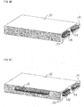
- FIG 3A a battery 10 with a first terminal 16 and a second terminal 17 is shown.
- the first terminal 16 and the second terminal 17 are arranged at a side surface of the battery 10.
- the first terminal 16 comprises two contacts 21 which are marked hatched.
- the second terminal 17 comprises one contact 21 which is marked solid.
- the contacts 21 of the first terminal 16 and of the second terminal 17 have the same shape.
- the first terminal 16 and the second terminal 17 are coplanar.
- the first terminal 16 and the second terminal 17 are coplanar in order to reduce the extent of the magnetic field induced by the current flowing through the terminals 16, 17.
- FIG 3B an alternative to arrange the first terminal 16 and the second terminal 17 at a side surface of the battery 10 is shown.
- Both terminals 16, 17 comprise three contacts 21.
- a contact 21 of the first terminal 16 is arranged between two contacts 21 of the second terminal 17 in a coplanar arrangement.
- a contact 21 of the second terminal 17 is arranged between two contacts 21 of the first terminal 16 in a coplanar arrangement.
- FIG 3C an alternative to arrange the first terminal 16 and the second terminal 17 at a side surface of the battery 10 is shown.
- the battery 10 comprises the same contacts 21 as shown in figure 10B and furthermore two contacts 21 at a further side surface of the battery 10.
- a contact 21 of the first terminal 16 and a contact 21 of the second terminal 17 are arranged next to each other in a coplanar arrangement.
- the currents at the first terminal 16 and at the second terminal 17 can be high. Therefore, it is advantageous to distribute the current over several electrical contacts 21.
- first terminal 16 and the second terminal 17 at a side surface of the battery 10 are shown.
- the contacts 21 of the first terminal 16 are marked hatched and the contacts 21 of the second terminal 17 are marked solid.
- the terminals 16, 17 are arranged coplanar or coaxial in order to reduce the extent of the magnetic field induced by the current flowing through the terminals 16, 17.
- the first terminal 16 comprises one contact 21 and the second terminal 17 comprises two contacts 21. All contacts 21 are rectangular shaped and arranged coplanar. The first terminal 16 is arranged between the two contacts 21 of the second terminal 17.
- the first terminal 16 and the second terminal 17 each comprise three contacts 21.
- a first contact 21 of the first terminal 16 is circular shaped.
- the first contact 21 of the first terminal 16 is surrounded by a ring-shaped contact 21 of the second terminal 17.
- a second contact 21 of the second terminal 17 is circular shaped.
- the second contact 21 of the second terminal 17 is surrounded by a ring-shaped contact 21 of the first terminal 16.
- a third contact 21 of the first terminal 16 is circular shaped.
- the third contact 21 of the first terminal 16 is surrounded by a ring-shaped contact 21 of the second terminal 17.
- the first terminal 16 comprises eight contacts 21 and the second terminal 17 comprises one contact 21. All contacts 21 are rectangular shaped. The contacts 21 of the first terminal 16 are coaxially arranged around the second terminal 17.
- the first terminal 16 comprises seven contacts 21 and the second terminal 17 comprises eight contacts 21. All contacts 21 are circular shaped.
- the contacts 21 of both terminals 16, 17 are arranged in an alternating structure, this means in a checkerboard structure.
- the first terminal 16 comprises eight contacts 21 and the second terminal 17 comprises two contacts 21. All contacts 21 are rectangular shaped. The contacts 21 of the first terminal 16 are coaxially arranged around the contacts 21 of the second terminal 17.
- the first terminal 16 comprises six contacts 21 and the second terminal 17 comprises one contact 21. All contacts 21 are rectangular shaped.
- the two terminals 16, 17 are arranged coplanar and the second terminal 17 is arranged between the contacts 21 of the first terminal 16.
- first terminal 16 and the second terminal 17 each comprise one contact 21.
- the first terminal 16 is rectangular shaped.
- the second terminal 17 is arranged as a stripe that surrounds the first terminal 16.
- the first terminal 16 comprises five contacts 21 and the second terminal 17 comprises one contact 21.
- the contacts 21 of the first terminal 16 are circular shaped and are arranged along a line at the side surface of the battery 10.
- the second terminal 17 is arranged as a stripe that surrounds the contacts 21 of the first terminal 16.
- the first terminal 16 comprises five contacts 21 and the second terminal 17 comprises eight contacts 21.
- the contacts 21 of the first terminal 16 are circular shaped and are arranged along a line at the side surface of the battery 10.
- the contacts 21 of the second terminal 17 are rectangular shaped and coaxially arranged around the contacts 21 of the first terminal 16.
- FIG 5A a side view of the battery 10 with the first terminal 16 and the second terminal 17 is shown.
- the contacts 21 of the first terminal 16 and the second terminal 17 are arranged as plugs.
- FIG 5B a side view of the battery 10 with the first terminal 16 and the second terminal 17 is shown.
- the contacts 21 of the first terminal 16 and the second terminal 17 are arranged as sockets.
- FIG 6A another alternative to arrange the first terminal 16 and the second terminal 17 at a side surface of the battery 10 is shown.
- the first terminal 16 comprises several contacts 21 and the second terminal 17 comprises one contact 21.
- the contacts 21 of the first terminal 16 are arranged coaxially around the contact 21 of the second terminal 17.
- the two terminals 16, 17 are electrically isolated against each other.
- a clamp 27 is arranged around the terminals 16, 17 in order to induce force on an external terminal which can be connected to the battery 10. The induced force is indicated by the arrows. In this way the contact between the two terminals 16, 17 and the external terminal is improved and the contact resistance is decreased.
- FIG 6B another alternative to arrange the first terminal 16 and the second terminal 17 at a side surface of the battery 10 is shown.
- the only difference to the embodiment shown in figure 13A is that the external terminal can be fixed to the terminals 16, 17 of the battery 10 by screws 28.
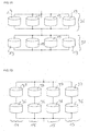
- FIG 7A a plurality of battery cells 13 of a battery 10 for an electric vehicle is shown.
- a first group 36 comprises four battery cells 13 connected to each other in parallel.
- a second group 37 also comprises four battery cells 13 connected to each other in parallel.
- the first group 36 and the second group 37 are connected with each other in series forming a line 14. It is possible that further groups comprising battery cells 13 are connected in series with the first group 36 and the second group 37.
- the battery cells 13 can be for example lithium ion batteries with rated battery voltages between 3 and 4 V.
- the number of groups connected to each other in series can be kept small enough such that the battery voltage does not exceed a desired value and at the same time the capacity of the battery 10 is as high as required for an electric vehicle.
- the battery voltage can for example be at least 6 V and at most 60 V.
- FIG 7B four lines of battery cells 13 of a battery 10 for an electric vehicle are shown.
- a line 14 comprises a first group 36 and a second group 37 connected to each other in series.
- Three further lines 15 also comprises a first group 36 and a second group 37 connected to each other in series.
- the line 14 is connected to the further lines 15 in parallel.
- the number of groups 36, 37 connected in series to each other in each line can be kept small enough such that the battery voltage does not exceed a desired value and at the same time the capacity of the battery 10 is as high as required for an electric vehicle.
- each line comprises at least a first group 36 and a second group 37 of battery cells 13.
- a fuse 24 is connected to a circuit node of a line 14 and to a circuit node of a further line 15.
- Two further fuses 24 are connected to further circuit nodes of the line 14 and of the further line 15, respectively.
- the line currents I l in the different lines can be regulated such that all line currents I l are the same.
- a battery cell 13 or a group 36, 37 of battery cells 13 in the line 14 is defective a high line current I l can arise in the line 14.
- the fuses 24 it is avoided that the high line current I l also flows through further lines 15.
- the fuses 24 can for example be realized as shown in figure 8 or as positive temperature coefficient thermistors.
- Each battery module 22 comprises two lines 14, 15 each comprising two groups 36, 37 of battery cells 13.
- the line 14 and the further lines 15 are connected with each other in parallel by an electric line which can be for example an electric cable.
- the two battery modules 22 are connected with each other in parallel.
- FIG 9B two battery modules 22 and four lines 14, 15 are shown. Each line 14, 15 is distributed over the two battery modules 22. This means, a first group 36 of for example the line 14 is arranged in one battery module 22 and the second group 37 of the line 14 is arranged in the other battery module 22. The groups 36, 37 of each line are connected in series with each other. The four lines 14, 15 are connected to each other in parallel.
- FIG 10 shows an electrical circuit with four battery modules 22 connected to each other in parallel.
- Three of the battery modules 22 can be disconnected from the other battery modules 22 by a switch 35 which is connected in series with the respective battery module 22.
- each of these battery modules 22 is assigned a respective switch 35 to activate and/or deactivate the respective battery module 22.
- the first switch 35 on the lefthand side of the electrical circuit is a DC/DC converter.
- the second switch 35 is a mechanical switch and the third switch 35 is a semiconductor switch.
- the fourth battery module 22 cannot be disconnected by a respective switch 35. It is also possible that further battery modules 22 are connected to the four battery modules 22 in parallel.
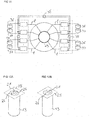
- groups 36, 37 of battery cells 13 connected to the electric machine 33 of the electric vehicle are shown.
- the groups 36, 37 can be comprised by different battery modules 22 which are not shown.
- the groups 36, 37 are arranged in four different lines where each line comprises a first group 36 and a second group 37.
- the electric machine 33 comprises different electrical phases ⁇ .
- the electrical phases ⁇ can each be supplied with a respective phase current.
- the phase currents comprise an AC and a DC component.
- Each line is connected to two or more electrical phases ⁇ of the electric machine 33.
- the electrical phases ⁇ are short-circuited on a short circuit ring 29 of the electric machine 30. Therefore, the line currents I l are equalized if the groups 36, 37 of battery cells 13 are connected with the electrical phases ⁇ .
- the electric machine 33 is employed to equalize the line currents I l of the different lines of battery cells 13. As the electric machine 33 is controlled by the AC components of the phase currents the regulation of the line currents I l can take place both when the electric machine 33 is operated and when it is not operated.
- switches 35 are arranged between the lines. If single battery modules 22 can be exchanged and be replaced by charged battery modules 22 the charging level of the charged battery modules 22 and the battery modules 22 which are not replaced can be very different. This means, high compensation currents can arise.
- the line currents I l By regulating the line currents I l by coupling the battery modules 22 to the electric machine 33 the losses during regulation of the line currents I l are smaller in comparison to losses during a regulation of the line currents I l by passive elements as for example a positive temperature coefficient thermistor.
- FIG 12A a battery cell 13 with an electrical contact 21 is shown.
- the electrical contact 21 is a contact comprising a screw.
- the electrical contact 21 of the battery cell 13 is connected to a metal sheet 25.
- the metal sheet 25 can comprise aluminum or copper and it can connect several battery cells 13 with each other in parallel.
- the metal sheet 25 comprises a circular shaped hole around the electrical contact 21 except for two connections 26.
- the connections 26 act as fuses 24. If the current flowing from the battery cell 13 towards the metal sheet 25 is too high the two connections 26 will warm up and melt. For a better stability against for example torque exerted on the electrical contact 21 the metal sheet 25 comprises two connections 26 instead of only one.
- FIG 12B a battery cell 13 with an electrical contact 21 which is a welding contact is shown.
- the metal sheet 25 only comprises one connection 26 as a fuse 24 since no torque is exerted on the electrical contact 21.
- FIG 13 six battery cells 13 which are connected with metal sheets 25 are shown.
- Three battery cells 13 are connected with a metal sheet 25 on a top side of the battery cells 13 and with another metal sheet 25 on a bottom side of the battery cells 13 facing away from the top side.
- Three further battery cells 13 are also connected with a metal sheet 25 on the top side and with another metal sheet 25 on the bottom side of the battery cells 13.
- the two metal sheets 25 on the top side of the battery cells 13 are connected with each other by two thin connections 26.
- the two metal sheets 25 on the bottom side of the battery cells 13 are connected with each other by two thin connections 26.
- the connections 26 act as fuses 24 as described with figure 12A .
- the power system 32 comprises a circuit arrangement 11 as described above.
- the power system 32 further comprises an electric machine 33 and a power net 34, where the first output 18 is electrically coupled to the electric machine 33 and the second output 19 is electrically coupled to the power net 34.
- the battery 10 is configured to supply both the electric machine 33 and the power net 34 of the electric vehicle with power. Consequently, only one battery 10 is required for the electric vehicle.
- the power system 32 can be comprised by an electric vehicle.
- the power system is arranged to supply the electric vehicle with power, to enable movement of the electric vehicle and to enable the operation of the devices of the power net 34.
- the electric machine 33 and the power net 34 are supplied with the same voltage level by the battery 10, as neither between the first terminal 16 of the battery 10 and the first output 18 nor between the first terminal 16 and the second output 19 converters are arranged.
Landscapes
- Engineering & Computer Science (AREA)
- Power Engineering (AREA)
- Transportation (AREA)
- Mechanical Engineering (AREA)
- Life Sciences & Earth Sciences (AREA)
- Sustainable Development (AREA)
- Sustainable Energy (AREA)
- Electric Propulsion And Braking For Vehicles (AREA)
Priority Applications (4)
| Application Number | Priority Date | Filing Date | Title |
|---|---|---|---|
| EP17169961.4A EP3402031A1 (fr) | 2017-05-08 | 2017-05-08 | Agencement de circuit et système d'alimentation |
| CN201880029921.7A CN110651408A (zh) | 2017-05-08 | 2018-05-02 | 电路装置和电力系统 |
| US16/609,759 US11673479B2 (en) | 2017-05-08 | 2018-05-02 | Circuit arrangement and power system |
| PCT/EP2018/061194 WO2018206366A1 (fr) | 2017-05-08 | 2018-05-02 | Agencement de circuit et système d'alimentation |
Applications Claiming Priority (1)
| Application Number | Priority Date | Filing Date | Title |
|---|---|---|---|
| EP17169961.4A EP3402031A1 (fr) | 2017-05-08 | 2017-05-08 | Agencement de circuit et système d'alimentation |
Publications (1)
| Publication Number | Publication Date |
|---|---|
| EP3402031A1 true EP3402031A1 (fr) | 2018-11-14 |
Family
ID=58672519
Family Applications (1)
| Application Number | Title | Priority Date | Filing Date |
|---|---|---|---|
| EP17169961.4A Pending EP3402031A1 (fr) | 2017-05-08 | 2017-05-08 | Agencement de circuit et système d'alimentation |
Country Status (4)
| Country | Link |
|---|---|
| US (1) | US11673479B2 (fr) |
| EP (1) | EP3402031A1 (fr) |
| CN (1) | CN110651408A (fr) |
| WO (1) | WO2018206366A1 (fr) |
Citations (3)
| Publication number | Priority date | Publication date | Assignee | Title |
|---|---|---|---|---|
| EP1641066A2 (fr) * | 2004-09-22 | 2006-03-29 | Howaldtswerke-Deutsche Werft GmbH | Ensemble de batteries d'un sous-marin |
| US20130113495A1 (en) * | 2011-09-28 | 2013-05-09 | Alliance For Sustainable Energy, Llc | Fail-Safe Designs for Large Capacity Battery Systems |
| US20160272191A1 (en) * | 2015-03-20 | 2016-09-22 | GM Global Technology Operations LLC | Method of controlling a powertrain of a vehicle |
Family Cites Families (12)
| Publication number | Priority date | Publication date | Assignee | Title |
|---|---|---|---|---|
| JP2944095B2 (ja) * | 1988-03-11 | 1999-08-30 | ブラック アンド デッカー インコーポレイティド | 電池式工具の電池ケース及び充電器 |
| US7253540B1 (en) | 2000-03-15 | 2007-08-07 | Ct Concept Technologie Ag | Method for operating a parallel arrangement of semiconductor power switches |
| EP1313193A1 (fr) | 2001-11-19 | 2003-05-21 | Dialog Semiconductor GmbH | Système de protection de batterie avec fusible à claquage séquentiel |
| JP3776348B2 (ja) * | 2001-12-10 | 2006-05-17 | 本田技研工業株式会社 | 車両用電源装置 |
| JP4127705B2 (ja) * | 2005-10-07 | 2008-07-30 | 日本航空電子工業株式会社 | 電気コネクタ |
| US7671565B2 (en) | 2006-02-13 | 2010-03-02 | Tesla Motors, Inc. | Battery pack and method for protecting batteries |
| US8467891B2 (en) * | 2009-01-21 | 2013-06-18 | Utc Fire & Security Americas Corporation, Inc. | Method and system for efficient optimization of audio sampling rate conversion |
| US9793889B2 (en) * | 2011-03-15 | 2017-10-17 | Infineon Technologies Ag | Semiconductor device including a circuit to compensate for parasitic inductance |
| JPWO2012132435A1 (ja) * | 2011-03-29 | 2014-07-24 | パナソニック株式会社 | 車両用電源装置 |
| FR2979770B1 (fr) * | 2011-09-01 | 2013-09-13 | Converteam Technology Ltd | Convertisseur de puissance elevee avec des transistors de faible puissance connectes en parallele |
| CA2973324A1 (fr) * | 2015-01-16 | 2016-07-21 | Sony Corporation | Module de stockage d'alimentation, systeme de stockage d'alimentation, appareil electronique, vehicule electrique et systeme d'alimentation |
| US11529859B2 (en) * | 2016-04-01 | 2022-12-20 | Faraday & Future Inc. | Electric vehicle battery management |
-
2017
- 2017-05-08 EP EP17169961.4A patent/EP3402031A1/fr active Pending
-
2018
- 2018-05-02 CN CN201880029921.7A patent/CN110651408A/zh active Pending
- 2018-05-02 US US16/609,759 patent/US11673479B2/en active Active
- 2018-05-02 WO PCT/EP2018/061194 patent/WO2018206366A1/fr not_active Ceased
Patent Citations (3)
| Publication number | Priority date | Publication date | Assignee | Title |
|---|---|---|---|---|
| EP1641066A2 (fr) * | 2004-09-22 | 2006-03-29 | Howaldtswerke-Deutsche Werft GmbH | Ensemble de batteries d'un sous-marin |
| US20130113495A1 (en) * | 2011-09-28 | 2013-05-09 | Alliance For Sustainable Energy, Llc | Fail-Safe Designs for Large Capacity Battery Systems |
| US20160272191A1 (en) * | 2015-03-20 | 2016-09-22 | GM Global Technology Operations LLC | Method of controlling a powertrain of a vehicle |
Also Published As
| Publication number | Publication date |
|---|---|
| US11673479B2 (en) | 2023-06-13 |
| US20200062134A1 (en) | 2020-02-27 |
| WO2018206366A1 (fr) | 2018-11-15 |
| CN110651408A (zh) | 2020-01-03 |
Similar Documents
| Publication | Publication Date | Title |
|---|---|---|
| US11063308B2 (en) | Battery for an electric vehicle | |
| US10596917B2 (en) | Vehicle and electrical system with dual battery modules | |
| US11358486B2 (en) | Electric powertrain with multi-pack battery system | |
| US10828994B2 (en) | Battery system with battery control | |
| CN102714421B (zh) | 能够用于电池的并联充电和串联放电的充电触点列阵 | |
| JP6346887B2 (ja) | バッテリの充電平衡 | |
| CN108352717B (zh) | 用于车辆的储存器系统 | |
| US20200106287A1 (en) | Charging apparatus | |
| US11451118B2 (en) | Conductor arrangement and transportable electrical drive device | |
| US9537132B2 (en) | Battery having a plurality of battery modules arranged in battery strings, and method for operating the battery | |
| US8907628B2 (en) | Automotive bipolar electrical system | |
| CN113557631A (zh) | 具有集成保险丝的高压层压配电系统 | |
| CN114312480A (zh) | 带有多电池组电池系统和相互排斥的三路接触器的电动力总成 | |
| CN111038419A (zh) | 可配置的车辆电源插座系统 | |
| IT201900001099A1 (it) | Gruppo e metodo di ricarica e alimentazione per un veicolo elettrico, e veicolo elettrico comprendente il gruppo di ricarica e alimentazione | |
| US20260070465A1 (en) | Charging and discharging circuit, battery control circuit and electrical device | |
| EP2409376A1 (fr) | Systeme et procede permettant la commande d'une unite de stockage d'energie | |
| US11673479B2 (en) | Circuit arrangement and power system | |
| US20160332528A1 (en) | Electrochemical composite storage system | |
| JP2019134635A (ja) | 充放電装置及び充放電システム | |
| CN116937085A (zh) | 带有并联导体布线的电池组 | |
| KR20190063065A (ko) | 배터리 일체형 저전압 디씨-디씨 컨버터 | |
| US10744899B2 (en) | Balancing energy in a parallelized battery system | |
| EP4510308A2 (fr) | Bloc-batterie de véhicule | |
| JP7666602B2 (ja) | 充電装置 |
Legal Events
| Date | Code | Title | Description |
|---|---|---|---|
| PUAI | Public reference made under article 153(3) epc to a published international application that has entered the european phase |
Free format text: ORIGINAL CODE: 0009012 |
|
| STAA | Information on the status of an ep patent application or granted ep patent |
Free format text: STATUS: THE APPLICATION HAS BEEN PUBLISHED |
|
| AK | Designated contracting states |
Kind code of ref document: A1 Designated state(s): AL AT BE BG CH CY CZ DE DK EE ES FI FR GB GR HR HU IE IS IT LI LT LU LV MC MK MT NL NO PL PT RO RS SE SI SK SM TR |
|
| AX | Request for extension of the european patent |
Extension state: BA ME |
|
| STAA | Information on the status of an ep patent application or granted ep patent |
Free format text: STATUS: REQUEST FOR EXAMINATION WAS MADE |
|
| 17P | Request for examination filed |
Effective date: 20190508 |
|
| RBV | Designated contracting states (corrected) |
Designated state(s): AL AT BE BG CH CY CZ DE DK EE ES FI FR GB GR HR HU IE IS IT LI LT LU LV MC MK MT NL NO PL PT RO RS SE SI SK SM TR |
|
| RAP1 | Party data changed (applicant data changed or rights of an application transferred) |
Owner name: MOLABO GMBH |
|
| STAA | Information on the status of an ep patent application or granted ep patent |
Free format text: STATUS: EXAMINATION IS IN PROGRESS |
|
| 17Q | First examination report despatched |
Effective date: 20210514 |