EP3402032B1 - Système d'inspection et/ou de maintenance avec une interface électrique - Google Patents
Système d'inspection et/ou de maintenance avec une interface électrique Download PDFInfo
- Publication number
- EP3402032B1 EP3402032B1 EP17209142.3A EP17209142A EP3402032B1 EP 3402032 B1 EP3402032 B1 EP 3402032B1 EP 17209142 A EP17209142 A EP 17209142A EP 3402032 B1 EP3402032 B1 EP 3402032B1
- Authority
- EP
- European Patent Office
- Prior art keywords
- electrically conductive
- housing
- unit
- electrical
- inspection
- Prior art date
- Legal status (The legal status is an assumption and is not a legal conclusion. Google has not performed a legal analysis and makes no representation as to the accuracy of the status listed.)
- Active
Links
Images


Classifications
-
- H—ELECTRICITY
- H01—ELECTRIC ELEMENTS
- H01R—ELECTRICALLY-CONDUCTIVE CONNECTIONS; STRUCTURAL ASSOCIATIONS OF A PLURALITY OF MUTUALLY-INSULATED ELECTRICAL CONNECTING ELEMENTS; COUPLING DEVICES; CURRENT COLLECTORS
- H01R13/00—Details of coupling devices of the kinds covered by groups H01R12/70 or H01R24/00 - H01R33/00
- H01R13/62—Means for facilitating engagement or disengagement of coupling parts or for holding them in engagement
- H01R13/6205—Two-part coupling devices held in engagement by a magnet
-
- H—ELECTRICITY
- H01—ELECTRIC ELEMENTS
- H01R—ELECTRICALLY-CONDUCTIVE CONNECTIONS; STRUCTURAL ASSOCIATIONS OF A PLURALITY OF MUTUALLY-INSULATED ELECTRICAL CONNECTING ELEMENTS; COUPLING DEVICES; CURRENT COLLECTORS
- H01R13/00—Details of coupling devices of the kinds covered by groups H01R12/70 or H01R24/00 - H01R33/00
- H01R13/02—Contact members
- H01R13/22—Contacts for co-operating by abutting
- H01R13/24—Contacts for co-operating by abutting resilient; resiliently-mounted
- H01R13/2464—Contacts for co-operating by abutting resilient; resiliently-mounted characterized by the contact point
- H01R13/2478—Contacts for co-operating by abutting resilient; resiliently-mounted characterized by the contact point spherical
-
- H—ELECTRICITY
- H01—ELECTRIC ELEMENTS
- H01R—ELECTRICALLY-CONDUCTIVE CONNECTIONS; STRUCTURAL ASSOCIATIONS OF A PLURALITY OF MUTUALLY-INSULATED ELECTRICAL CONNECTING ELEMENTS; COUPLING DEVICES; CURRENT COLLECTORS
- H01R13/00—Details of coupling devices of the kinds covered by groups H01R12/70 or H01R24/00 - H01R33/00
- H01R13/64—Means for preventing incorrect coupling
-
- H—ELECTRICITY
- H01—ELECTRIC ELEMENTS
- H01R—ELECTRICALLY-CONDUCTIVE CONNECTIONS; STRUCTURAL ASSOCIATIONS OF A PLURALITY OF MUTUALLY-INSULATED ELECTRICAL CONNECTING ELEMENTS; COUPLING DEVICES; CURRENT COLLECTORS
- H01R33/00—Coupling devices specially adapted for supporting apparatus and having one part acting as a holder providing support and electrical connection via a counterpart which is structurally associated with the apparatus, e.g. lamp holders; Separate parts thereof
- H01R33/05—Two-pole devices
- H01R33/18—Two-pole devices having only abutting contacts
-
- H—ELECTRICITY
- H02—GENERATION; CONVERSION OR DISTRIBUTION OF ELECTRIC POWER
- H02J—ELECTRIC POWER NETWORKS; CIRCUIT ARRANGEMENTS OR SYSTEMS FOR SUPPLYING OR DISTRIBUTING ELECTRIC POWER; SYSTEMS FOR STORING ELECTRIC ENERGY
- H02J7/00—Circuit arrangements for charging or discharging batteries or for supplying loads from batteries
- H02J7/50—Circuit arrangements for charging or discharging batteries or for supplying loads from batteries acting upon multiple batteries simultaneously or sequentially
-
- H—ELECTRICITY
- H02—GENERATION; CONVERSION OR DISTRIBUTION OF ELECTRIC POWER
- H02J—ELECTRIC POWER NETWORKS; CIRCUIT ARRANGEMENTS OR SYSTEMS FOR SUPPLYING OR DISTRIBUTING ELECTRIC POWER; SYSTEMS FOR STORING ELECTRIC ENERGY
- H02J7/00—Circuit arrangements for charging or discharging batteries or for supplying loads from batteries
- H02J7/70—Circuit arrangements for charging or discharging batteries or for supplying loads from batteries characterised by the mechanical construction
-
- H—ELECTRICITY
- H04—ELECTRIC COMMUNICATION TECHNIQUE
- H04Q—SELECTING
- H04Q9/00—Arrangements in telecontrol or telemetry systems for selectively calling a substation from a main station, in which substation desired apparatus is selected for applying a control signal thereto or for obtaining measured values therefrom
-
- B—PERFORMING OPERATIONS; TRANSPORTING
- B08—CLEANING
- B08B—CLEANING IN GENERAL; PREVENTION OF FOULING IN GENERAL
- B08B9/00—Cleaning hollow articles by methods or apparatus specially adapted thereto
- B08B9/02—Cleaning pipes or tubes or systems of pipes or tubes
- B08B9/027—Cleaning the internal surfaces; Removal of blockages
- B08B9/04—Cleaning the internal surfaces; Removal of blockages using cleaning devices introduced into and moved along the pipes
-
- H—ELECTRICITY
- H01—ELECTRIC ELEMENTS
- H01R—ELECTRICALLY-CONDUCTIVE CONNECTIONS; STRUCTURAL ASSOCIATIONS OF A PLURALITY OF MUTUALLY-INSULATED ELECTRICAL CONNECTING ELEMENTS; COUPLING DEVICES; CURRENT COLLECTORS
- H01R2201/00—Connectors or connections adapted for particular applications
- H01R2201/20—Connectors or connections adapted for particular applications for testing or measuring purposes
-
- H—ELECTRICITY
- H04—ELECTRIC COMMUNICATION TECHNIQUE
- H04Q—SELECTING
- H04Q2209/00—Arrangements in telecontrol or telemetry systems
- H04Q2209/30—Arrangements in telecontrol or telemetry systems using a wired architecture
-
- H—ELECTRICITY
- H04—ELECTRIC COMMUNICATION TECHNIQUE
- H04Q—SELECTING
- H04Q2209/00—Arrangements in telecontrol or telemetry systems
- H04Q2209/80—Arrangements in the sub-station, i.e. sensing device
- H04Q2209/88—Providing power supply at the sub-station
Definitions
- the invention relates to a sewer inspection and/or maintenance system with an electrical interface.
- Inspection and/or maintenance systems in particular for the inspection and/or maintenance of channels or pipes, are known from the prior art.
- Inspection and/or maintenance units of such systems usually have electrical components (e.g. a camera module in an inspection system or a camera module in a rinsing head) that have to be supplied with electrical energy. If no electrical cable for the power supply of the inspection and/or maintenance units is to be introduced into the channel, it is known to provide accumulators for the power supply in the inspection and/or maintenance units.
- Such accumulators must be charged regularly. To this end, the accumulator is removed from the inspection and/or maintenance unit and placed in a charger for charging.
- the disadvantage here is that the housing cover of the inspection and / or maintenance unit, behind which the accumulator is arranged, must be designed at least fluid-tight to Prevent water from entering the canal. This tightness cannot always be guaranteed, especially after repeated opening/closing.
- the housing cover is subject to a certain amount of wear when opening/closing, which can also have a negative effect on the tightness.
- the US 2013/0164949 A1 discloses a system for coupling electronic devices to chargers.
- the charging unit includes charging contacts, the charging contacts being brought into contact with charging contacts of the electronic device during coupling.
- the charging unit housing is waterproof and may include a magnet.
- the charging contacts of the electronic device may include a magnetic material such that the coupling between the device and the charging unit is secured by a magnetic force.
- the U.S. 2002/0190682 A1 discloses an inspection system having a power source such as a rechargeable battery.
- the power source of the inspection system can be charged by an external charging unit via electrical contacts of the inspection system.
- the DE 10 2008 015 388 A1 discloses a system with a prosthesis having a storage device for electrical energy and contact surfaces for electrical contact with a charging device, and a charging device, the charging device being held on the prosthesis via a magnet.
- the U.S. 2007/0072443 A1 discloses a system having an electrical connector and a receptacle for receiving the connector.
- the plug is held in the socket by a magnet.
- the object of the present invention is therefore to provide solutions that allow a power supply and/or data transmission from and to the inspection and/or maintenance units to be implemented in a structurally simple manner, while at the same time a coupling is secured against unintentional loosening between the external unit and the sewer inspection and/or maintenance system is guaranteed.
- the housing therefore has at least two electrically conductive sections, ie three or more electrically conductive sections can also be provided, with each electrically conductive section being electrically insulated from the other electrically conductive sections.
- the external unit also has at least two electrical contacts, i.e. three or more electrical contacts can also be provided.
- An electrical load and/or an energy store in particular a rechargeable battery, can be arranged in the housing and the electrically conductive sections can be coupled to the electrical load and/or to the energy store.
- the two electrically conductive sections of the housing each have a magnetic or ferromagnetic material, at least in sections, and the external unit has at least one magnet which, when the electrical contacts make contact with the electrically conductive sections, is magnetic with at least one of the magnetic sections works together.
- the external unit can thus be arranged on a roughly flat surface of the housing, where it is held by the magnets in such a way that the two electrical contacts of the external unit are or are held in operative connection with the respective electrically conductive section of the housing.
- the resulting tear-off behavior is advantageous here, ie even if the external unit is removed unintentionally and by force, for example from the inspection and/or maintenance unit, neither the external unit nor the inspection and/or maintenance unit is damaged.
- An actuating means preferably a spring element, can be assigned to each of the coupling elements.
- the spring element can be designed in such a way that the coupling elements are pressed into the coupling cutouts after the external unit has been received in the cutout of the housing. When the external unit is removed from the recess in the housing, the coupling elements are pressed out of the coupling recesses against the spring force.
- the electrical contacts and the electrically conductive sections can be provided for the transmission of electrical energy.
- At least one of the electrical contacts and at least one of the electrically conductive sections can be used for signal or data transmission.
- the external unit includes at least one of the charging unit, light source, permanent power supply, external accumulator and data processing device.
- the electrical load can include at least one of a data processing device, image recording device, light source, sensor and manipulator.
- the system according to the invention has an inspection and/or maintenance unit and an external unit.
- FIG Figures 1 to 4 a system is described in which the external unit is a charging unit and in which an accumulator is arranged in the housing of the inspection and/or maintenance unit, which accumulator can be charged with the charging unit if required.
- an electrical consumer such as an external light source
- an external unit for example, as with reference to FIG figure 5 will be described, or a data processing device in order to process data transmission via the electrical coupling.
- an external accumulator can also be provided, which can be used, for example, for an emergency power supply. if the energy supply for the inspection and/or maintenance unit can no longer be guaranteed with the accumulator arranged in the housing of the inspection and/or maintenance unit.
- an electrical consumer such as an illuminant or an image recording device
- an electrical consumer can also be provided in the housing, which is supplied with electrical energy from an external accumulator via the electrical coupling.
- a data processing device for example a microcontroller, can also be arranged in the housing, it being possible for data transmission to be handled with an external data processing device via the electrical coupling.
- All embodiments or exemplary embodiments have in common that the electrical coupling between the external unit and the inspection and/or maintenance unit using electrically conductive sections of the housing of the inspection and/or maintenance unit, which are electrically insulated from one another, and using electrical contacts of the external unit is produced, the electrical contacts of the external unit also being electrically isolated from one another.
- FIG. 1 shows a schematic diagram of a system that has an inspection and/or maintenance unit 10 and a loading unit 20 .
- the inspection and/or maintenance unit 10 is also referred to below as the inspection unit 10 in a simplified manner, which can in principle also be implemented in the case of maintenance units.
- the inspection unit 10 has a housing in which all electrical and electronic components are accommodated, for example a camera module and/or sensors. Also housed in the housing is an energy store, not shown here, such as an accumulator, which is provided for supplying energy to the electrical and electronic components.
- an energy store not shown here, such as an accumulator, which is provided for supplying energy to the electrical and electronic components.
- the housing itself is preferably designed to be fluid and/or gas-tight.
- the housing has a first electrically conductive section 11a and a second electrically conductive section 11b, which can carry different electrical potentials and are electrically insulated from one another, for example by means of an insulating layer 12.
- the housing can also have more than two electrically conductive sections.
- the electrically conductive sections 11a, 11b of the housing are coupled to the battery (not shown here) or to corresponding charging electronics, which in turn are coupled to the battery, so that the battery can be charged via the two electrically conductive sections 11a, 11b.
- the remaining sections of the housing can also consist of an electrically non-conductive material.
- the electrically conductive sections 11a, 11b of the housing provide contact points to which the charging unit 20 can be electrically contacted in order to apply an electric current to the two electrically conductive sections 11a, 11b for charging the accumulator.
- the voltage and/or the amperage of the electrical current provided by the charging unit 20 are set in such a way that there is no danger to operating personnel during the charging process should the operating personnel accidentally come into contact with the electrically conductive sections 11a, 11b of the housing .
- a first electrical contact 22a and a second electrical contact 22b are arranged on the charging unit 20 .
- These two electrical contacts 22a, 22b are designed and arranged on the charging unit 20 such that when the charging unit 20 is brought up to the inspection unit 10 they come into contact with the respective electrically conductive sections 11a, 11b of the housing.
- the two electrical contacts 22a, 22b are in turn coupled to an electrical power source which provides the electrical power for charging the accumulator.
- the two electrical contacts 22a, 22b are at in 1 basic sketch shown designed slightly raised. However, they can also be configured as largely flat contact plates, for example. However, the geometry of the electrical contacts 22a, 22b essentially depends on the geometry of the contact points of the electrically conductive sections 11a, 11b of the housing.
- magnets (at least one magnet) are arranged, which interact magnetically when the charging unit 20 is brought to the housing of the inspection unit 10 with the electrically conductive sections 11a, 11b of the housing.
- the housing has a magnetic or ferromagnetic material, at least in sections. The charging unit 20 is then held on the housing 10 with the aid of the magnetic force.
- Two magnets can also be arranged on the housing of the inspection unit 10, which correspond to the two magnets 21 of the loading unit. It is advantageous here if both on the charging unit 20 and on the housing of the inspection unit 10 one magnet has its positive pole and one magnet has its negative pole facing the surface of the housing or the surface of the charging unit 20 . In this way, reverse polarity protection can be achieved when the charging unit 20 is brought to the housing, because the magnets of the charging unit only adhere to the magnets of the housing when the charging unit is aligned (in which the negative poles face the positive poles) relative to the housing.
- FIG. 2 shows an alternative embodiment of the in 1 system shown using a schematic diagram. This in 2 The system shown differs from that in 1 system shown only in the concrete design of the reverse polarity protection.
- a peg is provided on the surface of the charging unit 20, which corresponds to a groove on the surface of the housing.
- a groove is provided on the surface of the charging unit 20, which corresponds to a peg on the surface of the housing.
- the grooves are in each case recesses or indentations on the surface, into which the respective pins can be brought into engagement.
- FIG. 3 shows an embodiment of a system according to the invention based on a schematic diagram.
- the housing of the inspection unit 10 has two electrically conductive sections 11a, 11b which are electrically insulated from one another.
- the housing has a recess 13 in which the charging unit 20 can be accommodated at least partially by the charging unit 20 being pushed into this recess 13 .
- the two electrically insulated walls of the recess 13 are each part of the electrically conductive sections 11a, 11b of the housing, which are each brought into contact with the electrical contacts 22a, 22b arranged on the charging unit 20 when the charging unit 20 is inserted into the recess 13 becomes.
- the charging unit 20 can be secured in the recess 13 by means of magnets arranged on the charging unit 20 and on the wall of the recess.
- this securing is achieved with the aid of movably designed electrical contacts 22a, 22b, which are designed spherically here.
- the spherical electrical contacts 22a, 22b are each arranged in a radial blind hole of the charging unit 20.
- the electrical contacts 22a, 22b can also have another suitable geometry.
- the two electrical contacts 22a, 22b are each assigned an actuating means, which is designed as a spring element 23 here.
- the spring elements push the electrical contacts 22a, 22b at least partially out of the respective blind hole, so that the section of the electrical contacts 22a, 22b protruding from the blind hole can be engaged in a coupling recess 14 in the wall.
- the electrical contacts 22a, 22b are here secured against falling out of the blind holes.
- the electrical contacts 22a, 22b have two functions here. On the one hand, they come into contact with the electrically conductive sections 11a, 11b of the housing in order to be able to charge the accumulator arranged in the housing. On the other hand, they secure the charging unit from being released too easily from the recess 13.
- separate coupling elements can also be provided on the loading unit, which are only used to secure the loading unit in the recess 13 .
- FIG. 4 shows an example of an inspection and/or maintenance unit 10 whose accumulator can be charged.
- the inspection and/or maintenance unit 10 shown here is an inspection head that can be attached to a front end of a sliding eel, for example, and can be brought into a channel with the sliding eel and moved there.
- the inspection head can also be mounted on a trolley.
- the inspection head 10 or the housing of the inspection head has an axial recess 30 at the distal end, in which a camera module 40 is arranged.
- the opening of the recess 30 is sealed gas-tight and/or fluid-tight with a protective disk 31 .
- the housing of the inspection head 10 has two electrically conductive sections 11a, 11b that are insulated from one another.
- the charging unit 20 is brought up to the distal end of the inspection head 10, so that the two electrical contacts 22a, 22b are electrically contacted with the two electrically conductive sections 11a, 11b.
- the principle shown can, for example, also be applied to a rinsing head which, in addition to the rinsing nozzles, also has electrical or electronic components which are supplied with electrical energy by an accumulator arranged in the rinsing head.
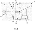
- figure 5 shows another example of a system.
- the external unit has an illuminant 50 here.
- the two electrical contacts 2 22a and 22b are connected to the light source 50 .
- the inspection unit 10 has an accumulator 60, one pole of the accumulator 60 being connected to the first electrically conductive section 11a and the other Pole of the accumulator 60 is connected to the second electrically conductive portion 11b of the housing.
- the housing of the inspection unit 20 in the configuration of the system according to the invention described above, provision can be made for the housing of the inspection unit 20 to be designed to be fluid-tight and/or gas-tight.
Landscapes
- Engineering & Computer Science (AREA)
- Power Engineering (AREA)
- Computer Networks & Wireless Communication (AREA)
- Charge And Discharge Circuits For Batteries Or The Like (AREA)
Claims (8)
- Système d'inspection et/ou de maintenance de canalisations, comportant une interface électrique, le système d'inspection et/ou de maintenance de canalisations présentant- une unité d'inspection et/ou de maintenance de canalisations (10), et- une unité externe (20) qui peut être couplée électriquement à l'unité d'inspection et/ou de maintenance de canalisations (10),dans lequel- l'unité d'inspection et/ou de maintenance de canalisations (10) présente un boîtier conçu de manière étanche aux fluides et/ou aux gaz,- le boîtier présente une première section électriquement conductrice (11a) et au moins une seconde section électriquement conductrice (11b), les sections électriquement conductrices (11a ; 11b) étant isolées électriquement l'une de l'autre au moyen d'une couche isolante (12),- l'unité externe (20) présente un premier contact électrique (22a) et au moins un second contact électrique (22b),les sections électriquement conductrices (11a ; 11b) et les contacts électriques (22a ; 22b) étant conçus de manière à ce que le premier contact électrique (22a) puisse être électriquement mis en contact avec la première section électriquement conductrice (11a) et l'au moins un second contact électrique (22b) puisse être électriquement mis en contact avec l'au moins une seconde section électriquement conductrice (11b),le boîtier et l'unité externe (20) étant conçus de manière à pouvoir être couplés l'un à l'autre par complémentarité de forme et/ou à force, le boîtier présentant un évidement (13) comportant deux parois et dans lequel l'unité externe (20) peut être au moins partiellement reçue par complémentarité de forme et/ou à force,les deux parois étant électriquement isolées l'une de l'autre et faisant respectivement partie des sections électriquement conductrices (11a ; 11b) du boîtier, l'unité externe (20) présentant des éléments de couplage mobiles qui, lors du couplage de l'unité externe (20) au boîtier, viennent en prise dans des évidements de couplage (14) côté paroi correspondants du boîtier pour fixer l'unité externe (20) dans l'évidement (13), les éléments de couplage étant les contacts électriques (22a ; 22b),les contacts électriques (22a ; 22b) étant respectivement disposés dans un trou borgne radial de l'unité externe (20), etles contacts électriques (22a ; 22b) étant au moins partiellement poussés hors du trou borgne respectif lors du couplage de l'unité externe (20).
- Système d'inspection et/ou de maintenance de canalisations selon la revendication précédente, dans lequel un consommateur électrique et/ou un dispositif de stockage d'énergie, en particulier un accumulateur, sont disposés dans le boîtier, et les sections électriquement conductrices (11a ; 11b) sont couplées au consommateur électrique et/ou au dispositif de stockage d'énergie.
- Système d'inspection et/ou de maintenance de canalisations selon l'une des revendications précédentes, dans lequel les sections électriquement conductrices (11a ; 11b) du boîtier présentent respectivement un matériau magnétique ou ferromagnétique, au moins dans certaines régions, et l'unité externe (20) présentant au moins un aimant (21) qui interagit magnétiquement avec au moins l'une des sections magnétiques lorsque les contacts électriques (22a ; 22b) entrent en contact avec les sections électriquement conductrices (11a ; 11b).
- Système d'inspection et/ou de maintenance de canalisations selon l'une des revendications précédentes, dans lequel respectivement un moyen d'actionnement, de préférence un élément à ressort (23), est associé aux éléments de couplage.
- Système d'inspection et/ou de maintenance de canalisations selon l'une des revendications précédentes, dans lequel les contacts électriques (22a ; 22b) et les sections électriquement conductrices (11a ; 11b) sont prévus pour une transmission d'énergie électrique.
- Système d'inspection et/ou de maintenance de canalisations selon l'une des revendications précédentes, dans lequel au moins l'un des contacts électriques (22a ; 22b) et au moins l'une des sections électriquement conductrices (11a ; 11b) peuvent être utilisés pour une transmission de signaux ou de données.
- Système d'inspection et/ou de maintenance de canalisations selon l'une des revendications précédentes, dans lequel l'unité externe (20) comprend une unité de charge, et/ou un moyen d'éclairage, et/ou une alimentation en courant permanente, et/ou un accumulateur externe et/ou un appareil de traitement de données.
- Système d'inspection et/ou de maintenance de canalisations selon l'une des revendications 2 à 7, dans lequel le consommateur électrique comprend un appareil de traitement de données, et/ou un appareil d'enregistrement d'images, et/ou un moyen d'éclairage, et/ou un capteur et/ou un manipulateur.
Applications Claiming Priority (1)
| Application Number | Priority Date | Filing Date | Title |
|---|---|---|---|
| DE202017102821.6U DE202017102821U1 (de) | 2017-05-10 | 2017-05-10 | Inspektions- und/oder Wartungssystem mit elektrischer Schnittstelle |
Publications (2)
| Publication Number | Publication Date |
|---|---|
| EP3402032A1 EP3402032A1 (fr) | 2018-11-14 |
| EP3402032B1 true EP3402032B1 (fr) | 2022-10-26 |
Family
ID=59010772
Family Applications (1)
| Application Number | Title | Priority Date | Filing Date |
|---|---|---|---|
| EP17209142.3A Active EP3402032B1 (fr) | 2017-05-10 | 2017-12-20 | Système d'inspection et/ou de maintenance avec une interface électrique |
Country Status (3)
| Country | Link |
|---|---|
| US (1) | US10944209B2 (fr) |
| EP (1) | EP3402032B1 (fr) |
| DE (1) | DE202017102821U1 (fr) |
Families Citing this family (1)
| Publication number | Priority date | Publication date | Assignee | Title |
|---|---|---|---|---|
| CN211150950U (zh) * | 2020-01-03 | 2020-07-31 | 康普技术有限责任公司 | 电连接器组件 |
Citations (1)
| Publication number | Priority date | Publication date | Assignee | Title |
|---|---|---|---|---|
| US20070072443A1 (en) * | 2005-09-26 | 2007-03-29 | Apple Computer, Inc. | Magnetic connector for electronic device |
Family Cites Families (25)
| Publication number | Priority date | Publication date | Assignee | Title |
|---|---|---|---|---|
| US4317969A (en) * | 1978-09-01 | 1982-03-02 | Hannes Riegler | Electrical line-connector |
| US4451113A (en) * | 1982-08-02 | 1984-05-29 | Mid Coast Electronics | Magnetic safety receptacle and plug |
| CA2440344C (fr) * | 2001-03-07 | 2007-06-26 | Carnegie Mellon University | Systeme de controle robotique de conduites de gaz |
| US6824415B2 (en) * | 2001-11-01 | 2004-11-30 | Andrew Corporation | Coaxial connector with spring loaded coupling mechanism |
| US7125273B2 (en) * | 2004-06-08 | 2006-10-24 | Advance Thermo Control, Ltd. | Detachable power cord apparatus |
| JP4484143B2 (ja) * | 2004-06-09 | 2010-06-16 | 日東工器株式会社 | プラグ/ソケットアセンブリ |
| US7540754B2 (en) * | 2006-01-06 | 2009-06-02 | Apple Inc. | Universal Serial Bus plug and socket coupling arrangements |
| US7001199B1 (en) * | 2005-09-23 | 2006-02-21 | Ashour Badalpour | Electrical connection |
| US7347708B1 (en) * | 2006-08-17 | 2008-03-25 | Tzi-Chen Huang | Firm-structured plug |
| US7566224B2 (en) * | 2007-11-02 | 2009-07-28 | Hon Hai Precision Ind. Co., Ltd. | Electrical connector assembly with magnetic retention device |
| DE102008015388A1 (de) * | 2008-03-20 | 2009-06-04 | Otto Bock Healthcare Products Gmbh | System mit einer orthopädischen Einrichtung |
| KR100940510B1 (ko) * | 2008-09-30 | 2010-02-10 | 주식회사 아이엔피 | 분리형 플러그를 가지는 헤어드라이기의 아크방지장치 |
| WO2011114957A1 (fr) * | 2010-03-16 | 2011-09-22 | オリンパスメディカルシステムズ株式会社 | Système connecteur |
| US9500222B2 (en) * | 2010-05-04 | 2016-11-22 | Qwest Communications International Inc. | Passive suction base |
| US20130267112A1 (en) * | 2012-04-06 | 2013-10-10 | Delta Electronics (Thailand) Public Co., Ltd. | Power connector assembly and adapter plug with locking mechanism |
| US8894419B1 (en) * | 2012-08-14 | 2014-11-25 | Bby Solutions, Inc. | Magnetically connected universal computer power adapter |
| US8939785B2 (en) * | 2012-10-04 | 2015-01-27 | Gt Contact Co., Ltd. | Cable connector with spring-loaded plunger and assembly thereof |
| KR20140067356A (ko) * | 2012-11-26 | 2014-06-05 | 삼성전자주식회사 | 케이블 컨넥터 장치 |
| TWI538318B (zh) * | 2013-02-04 | 2016-06-11 | 金士頓數位股份有限公司 | 連接裝置及電子裝置總成 |
| KR101265730B1 (ko) * | 2013-02-20 | 2013-05-21 | (주)에스피에스 | 전력공급차단회로를 구비한 마그네틱 커넥터 모듈 |
| EP2779313B1 (fr) * | 2013-03-14 | 2019-07-31 | Siemens Aktiengesellschaft | Ensemble de raccordement et terminaison électrique |
| KR102056906B1 (ko) * | 2013-03-22 | 2019-12-17 | 삼성전자주식회사 | 자성 접속 장치 |
| JP2015049717A (ja) * | 2013-09-02 | 2015-03-16 | タイコエレクトロニクスジャパン合同会社 | コネクタ、コネクタ組立体及び無線通信モジュール |
| US9017092B1 (en) * | 2014-05-07 | 2015-04-28 | Microsoft Technology Licensing, Llc | Electronic connector |
| CN105098451B (zh) * | 2014-05-13 | 2018-03-06 | 富士康(昆山)电脑接插件有限公司 | 电连接器组合 |
-
2017
- 2017-05-10 DE DE202017102821.6U patent/DE202017102821U1/de active Active
- 2017-12-20 EP EP17209142.3A patent/EP3402032B1/fr active Active
-
2018
- 2018-05-08 US US15/973,833 patent/US10944209B2/en active Active
Patent Citations (1)
| Publication number | Priority date | Publication date | Assignee | Title |
|---|---|---|---|---|
| US20070072443A1 (en) * | 2005-09-26 | 2007-03-29 | Apple Computer, Inc. | Magnetic connector for electronic device |
Also Published As
| Publication number | Publication date |
|---|---|
| DE202017102821U1 (de) | 2017-05-19 |
| EP3402032A1 (fr) | 2018-11-14 |
| US10944209B2 (en) | 2021-03-09 |
| US20180331467A1 (en) | 2018-11-15 |
Similar Documents
| Publication | Publication Date | Title |
|---|---|---|
| EP2311148B1 (fr) | Dispositif de réalisation d'une connexion | |
| EP3122589B1 (fr) | Dispositif embrochable réalisé sous forme de prolongateur ou de fiche | |
| DE19930642A1 (de) | Elektromechanische Verbindungsvorrichtung | |
| WO2010009979A1 (fr) | Dispositif de connexion de chargement pour véhicule automobile à moteur électrique | |
| DE20104861U1 (de) | Elektromechanische Verbindungsvorrichtung | |
| EP3465842A1 (fr) | Liaison de raccordement électrique rapidement déconnectable, liaison de raccordement immobilisable ainsi que procédé de mise en contact d'un élément de contact électrique avec un conducteur électrique | |
| DE102016213757B4 (de) | Steckverbindung zum Koppeln von Hochvoltanschlüssen und System mit einer derartigen Steckverbindung | |
| DE202008014989U1 (de) | Vorrichtung zur Herstellung einer Verbindung | |
| EP2855101A1 (fr) | Outil | |
| DE102014011576B3 (de) | Brandmelder mit Verriegelung und Verfahren zum Ver- und Entriegeln von einem Melderteil mit einem Sockelteil eines Brandmelders | |
| EP3402032B1 (fr) | Système d'inspection et/ou de maintenance avec une interface électrique | |
| DE10206348A1 (de) | Elektromechanische Verbindungsvorrichtung | |
| DE102008013214B4 (de) | Ladesystem | |
| DE202018101382U1 (de) | Magnetischer elektrischer Steckverbinder | |
| DE102013009215A1 (de) | Steckvorrichtung, Aufnahmevorrichtung sowie Adaptervorrichtung zur Versorgung eines elektrisch antreibbaren Fortbewegungsmittels oder eines Hochstromverbrauchers | |
| DE69510656T2 (de) | System zum laden der batterie einer uhr ohne öffnen des deckels | |
| DE102020121222A1 (de) | Hermaphroditischer Stecker | |
| WO1999043074A1 (fr) | Dispositif pour la conversion de tension secteur en basse tension | |
| DE202018106611U1 (de) | Datenübertragungs- und/oder Ladekabel | |
| DE102024127324A1 (de) | Anschlusssystem zum elektrischen Verbinden zweier Hochspannungskomponenten und Kraftfahrzeug damit | |
| DE102023134637A1 (de) | Berührschutzelement für einen Steckverbinder | |
| DE9015660U1 (de) | Ladeeinrichtung für wiederaufladbare Batterien | |
| DE102023118039A1 (de) | Ladesteckverbinder für Elektro- und Hybridfahrzeuge | |
| DE102023129362A1 (de) | Ladesteckverbinder für Elektro- und Hybridfahrzeuge | |
| DE202011052324U1 (de) | "Elektrische Netz-Steckdose" |
Legal Events
| Date | Code | Title | Description |
|---|---|---|---|
| PUAI | Public reference made under article 153(3) epc to a published international application that has entered the european phase |
Free format text: ORIGINAL CODE: 0009012 |
|
| STAA | Information on the status of an ep patent application or granted ep patent |
Free format text: STATUS: THE APPLICATION HAS BEEN PUBLISHED |
|
| AK | Designated contracting states |
Kind code of ref document: A1 Designated state(s): AL AT BE BG CH CY CZ DE DK EE ES FI FR GB GR HR HU IE IS IT LI LT LU LV MC MK MT NL NO PL PT RO RS SE SI SK SM TR |
|
| AX | Request for extension of the european patent |
Extension state: BA ME |
|
| STAA | Information on the status of an ep patent application or granted ep patent |
Free format text: STATUS: REQUEST FOR EXAMINATION WAS MADE |
|
| 17P | Request for examination filed |
Effective date: 20190514 |
|
| RBV | Designated contracting states (corrected) |
Designated state(s): AL AT BE BG CH CY CZ DE DK EE ES FI FR GB GR HR HU IE IS IT LI LT LU LV MC MK MT NL NO PL PT RO RS SE SI SK SM TR |
|
| STAA | Information on the status of an ep patent application or granted ep patent |
Free format text: STATUS: EXAMINATION IS IN PROGRESS |
|
| 17Q | First examination report despatched |
Effective date: 20190930 |
|
| GRAP | Despatch of communication of intention to grant a patent |
Free format text: ORIGINAL CODE: EPIDOSNIGR1 |
|
| STAA | Information on the status of an ep patent application or granted ep patent |
Free format text: STATUS: GRANT OF PATENT IS INTENDED |
|
| RIC1 | Information provided on ipc code assigned before grant |
Ipc: F16L 55/00 20060101ALN20220419BHEP Ipc: B08B 9/00 20060101ALN20220419BHEP Ipc: H04Q 9/00 20060101ALI20220419BHEP Ipc: H01R 13/62 20060101ALI20220419BHEP Ipc: H02J 7/00 20060101AFI20220419BHEP |
|
| INTG | Intention to grant announced |
Effective date: 20220518 |
|
| GRAS | Grant fee paid |
Free format text: ORIGINAL CODE: EPIDOSNIGR3 |
|
| GRAA | (expected) grant |
Free format text: ORIGINAL CODE: 0009210 |
|
| STAA | Information on the status of an ep patent application or granted ep patent |
Free format text: STATUS: THE PATENT HAS BEEN GRANTED |
|
| AK | Designated contracting states |
Kind code of ref document: B1 Designated state(s): AL AT BE BG CH CY CZ DE DK EE ES FI FR GB GR HR HU IE IS IT LI LT LU LV MC MK MT NL NO PL PT RO RS SE SI SK SM TR |
|
| REG | Reference to a national code |
Ref country code: GB Ref legal event code: FG4D Free format text: NOT ENGLISH |
|
| REG | Reference to a national code |
Ref country code: CH Ref legal event code: EP |
|
| REG | Reference to a national code |
Ref country code: DE Ref legal event code: R096 Ref document number: 502017014000 Country of ref document: DE |
|
| REG | Reference to a national code |
Ref country code: AT Ref legal event code: REF Ref document number: 1527772 Country of ref document: AT Kind code of ref document: T Effective date: 20221115 |
|
| REG | Reference to a national code |
Ref country code: IE Ref legal event code: FG4D Free format text: LANGUAGE OF EP DOCUMENT: GERMAN |
|
| REG | Reference to a national code |
Ref country code: LT Ref legal event code: MG9D |
|
| REG | Reference to a national code |
Ref country code: NL Ref legal event code: MP Effective date: 20221026 |
|
| PG25 | Lapsed in a contracting state [announced via postgrant information from national office to epo] |
Ref country code: NL Free format text: LAPSE BECAUSE OF FAILURE TO SUBMIT A TRANSLATION OF THE DESCRIPTION OR TO PAY THE FEE WITHIN THE PRESCRIBED TIME-LIMIT Effective date: 20221026 |
|
| PG25 | Lapsed in a contracting state [announced via postgrant information from national office to epo] |
Ref country code: SE Free format text: LAPSE BECAUSE OF FAILURE TO SUBMIT A TRANSLATION OF THE DESCRIPTION OR TO PAY THE FEE WITHIN THE PRESCRIBED TIME-LIMIT Effective date: 20221026 Ref country code: PT Free format text: LAPSE BECAUSE OF FAILURE TO SUBMIT A TRANSLATION OF THE DESCRIPTION OR TO PAY THE FEE WITHIN THE PRESCRIBED TIME-LIMIT Effective date: 20230227 Ref country code: NO Free format text: LAPSE BECAUSE OF FAILURE TO SUBMIT A TRANSLATION OF THE DESCRIPTION OR TO PAY THE FEE WITHIN THE PRESCRIBED TIME-LIMIT Effective date: 20230126 Ref country code: LT Free format text: LAPSE BECAUSE OF FAILURE TO SUBMIT A TRANSLATION OF THE DESCRIPTION OR TO PAY THE FEE WITHIN THE PRESCRIBED TIME-LIMIT Effective date: 20221026 Ref country code: FI Free format text: LAPSE BECAUSE OF FAILURE TO SUBMIT A TRANSLATION OF THE DESCRIPTION OR TO PAY THE FEE WITHIN THE PRESCRIBED TIME-LIMIT Effective date: 20221026 Ref country code: ES Free format text: LAPSE BECAUSE OF FAILURE TO SUBMIT A TRANSLATION OF THE DESCRIPTION OR TO PAY THE FEE WITHIN THE PRESCRIBED TIME-LIMIT Effective date: 20221026 |
|
| PG25 | Lapsed in a contracting state [announced via postgrant information from national office to epo] |
Ref country code: RS Free format text: LAPSE BECAUSE OF FAILURE TO SUBMIT A TRANSLATION OF THE DESCRIPTION OR TO PAY THE FEE WITHIN THE PRESCRIBED TIME-LIMIT Effective date: 20221026 Ref country code: PL Free format text: LAPSE BECAUSE OF FAILURE TO SUBMIT A TRANSLATION OF THE DESCRIPTION OR TO PAY THE FEE WITHIN THE PRESCRIBED TIME-LIMIT Effective date: 20221026 Ref country code: LV Free format text: LAPSE BECAUSE OF FAILURE TO SUBMIT A TRANSLATION OF THE DESCRIPTION OR TO PAY THE FEE WITHIN THE PRESCRIBED TIME-LIMIT Effective date: 20221026 Ref country code: IS Free format text: LAPSE BECAUSE OF FAILURE TO SUBMIT A TRANSLATION OF THE DESCRIPTION OR TO PAY THE FEE WITHIN THE PRESCRIBED TIME-LIMIT Effective date: 20230226 Ref country code: HR Free format text: LAPSE BECAUSE OF FAILURE TO SUBMIT A TRANSLATION OF THE DESCRIPTION OR TO PAY THE FEE WITHIN THE PRESCRIBED TIME-LIMIT Effective date: 20221026 Ref country code: GR Free format text: LAPSE BECAUSE OF FAILURE TO SUBMIT A TRANSLATION OF THE DESCRIPTION OR TO PAY THE FEE WITHIN THE PRESCRIBED TIME-LIMIT Effective date: 20230127 |
|
| REG | Reference to a national code |
Ref country code: DE Ref legal event code: R097 Ref document number: 502017014000 Country of ref document: DE |
|
| PG25 | Lapsed in a contracting state [announced via postgrant information from national office to epo] |
Ref country code: SM Free format text: LAPSE BECAUSE OF FAILURE TO SUBMIT A TRANSLATION OF THE DESCRIPTION OR TO PAY THE FEE WITHIN THE PRESCRIBED TIME-LIMIT Effective date: 20221026 Ref country code: RO Free format text: LAPSE BECAUSE OF FAILURE TO SUBMIT A TRANSLATION OF THE DESCRIPTION OR TO PAY THE FEE WITHIN THE PRESCRIBED TIME-LIMIT Effective date: 20221026 Ref country code: EE Free format text: LAPSE BECAUSE OF FAILURE TO SUBMIT A TRANSLATION OF THE DESCRIPTION OR TO PAY THE FEE WITHIN THE PRESCRIBED TIME-LIMIT Effective date: 20221026 Ref country code: DK Free format text: LAPSE BECAUSE OF FAILURE TO SUBMIT A TRANSLATION OF THE DESCRIPTION OR TO PAY THE FEE WITHIN THE PRESCRIBED TIME-LIMIT Effective date: 20221026 Ref country code: CZ Free format text: LAPSE BECAUSE OF FAILURE TO SUBMIT A TRANSLATION OF THE DESCRIPTION OR TO PAY THE FEE WITHIN THE PRESCRIBED TIME-LIMIT Effective date: 20221026 |
|
| REG | Reference to a national code |
Ref country code: CH Ref legal event code: PL |
|
| REG | Reference to a national code |
Ref country code: BE Ref legal event code: MM Effective date: 20221231 |
|
| PG25 | Lapsed in a contracting state [announced via postgrant information from national office to epo] |
Ref country code: SK Free format text: LAPSE BECAUSE OF FAILURE TO SUBMIT A TRANSLATION OF THE DESCRIPTION OR TO PAY THE FEE WITHIN THE PRESCRIBED TIME-LIMIT Effective date: 20221026 Ref country code: LU Free format text: LAPSE BECAUSE OF NON-PAYMENT OF DUE FEES Effective date: 20221220 Ref country code: AL Free format text: LAPSE BECAUSE OF FAILURE TO SUBMIT A TRANSLATION OF THE DESCRIPTION OR TO PAY THE FEE WITHIN THE PRESCRIBED TIME-LIMIT Effective date: 20221026 |
|
| PLBE | No opposition filed within time limit |
Free format text: ORIGINAL CODE: 0009261 |
|
| STAA | Information on the status of an ep patent application or granted ep patent |
Free format text: STATUS: NO OPPOSITION FILED WITHIN TIME LIMIT |
|
| 26N | No opposition filed |
Effective date: 20230727 |
|
| PG25 | Lapsed in a contracting state [announced via postgrant information from national office to epo] |
Ref country code: LI Free format text: LAPSE BECAUSE OF NON-PAYMENT OF DUE FEES Effective date: 20221231 Ref country code: IE Free format text: LAPSE BECAUSE OF NON-PAYMENT OF DUE FEES Effective date: 20221220 Ref country code: CH Free format text: LAPSE BECAUSE OF NON-PAYMENT OF DUE FEES Effective date: 20221231 |
|
| PG25 | Lapsed in a contracting state [announced via postgrant information from national office to epo] |
Ref country code: SI Free format text: LAPSE BECAUSE OF FAILURE TO SUBMIT A TRANSLATION OF THE DESCRIPTION OR TO PAY THE FEE WITHIN THE PRESCRIBED TIME-LIMIT Effective date: 20221026 Ref country code: BE Free format text: LAPSE BECAUSE OF NON-PAYMENT OF DUE FEES Effective date: 20221231 |
|
| REG | Reference to a national code |
Ref country code: AT Ref legal event code: MM01 Ref document number: 1527772 Country of ref document: AT Kind code of ref document: T Effective date: 20221220 |
|
| PG25 | Lapsed in a contracting state [announced via postgrant information from national office to epo] |
Ref country code: HU Free format text: LAPSE BECAUSE OF FAILURE TO SUBMIT A TRANSLATION OF THE DESCRIPTION OR TO PAY THE FEE WITHIN THE PRESCRIBED TIME-LIMIT; INVALID AB INITIO Effective date: 20171220 |
|
| PG25 | Lapsed in a contracting state [announced via postgrant information from national office to epo] |
Ref country code: AT Free format text: LAPSE BECAUSE OF NON-PAYMENT OF DUE FEES Effective date: 20221220 |
|
| PG25 | Lapsed in a contracting state [announced via postgrant information from national office to epo] |
Ref country code: CY Free format text: LAPSE BECAUSE OF FAILURE TO SUBMIT A TRANSLATION OF THE DESCRIPTION OR TO PAY THE FEE WITHIN THE PRESCRIBED TIME-LIMIT Effective date: 20221026 Ref country code: AT Free format text: LAPSE BECAUSE OF NON-PAYMENT OF DUE FEES Effective date: 20221220 |
|
| PG25 | Lapsed in a contracting state [announced via postgrant information from national office to epo] |
Ref country code: MK Free format text: LAPSE BECAUSE OF FAILURE TO SUBMIT A TRANSLATION OF THE DESCRIPTION OR TO PAY THE FEE WITHIN THE PRESCRIBED TIME-LIMIT Effective date: 20221026 Ref country code: IT Free format text: LAPSE BECAUSE OF FAILURE TO SUBMIT A TRANSLATION OF THE DESCRIPTION OR TO PAY THE FEE WITHIN THE PRESCRIBED TIME-LIMIT Effective date: 20221026 |
|
| PG25 | Lapsed in a contracting state [announced via postgrant information from national office to epo] |
Ref country code: MC Free format text: LAPSE BECAUSE OF FAILURE TO SUBMIT A TRANSLATION OF THE DESCRIPTION OR TO PAY THE FEE WITHIN THE PRESCRIBED TIME-LIMIT Effective date: 20221026 |
|
| PG25 | Lapsed in a contracting state [announced via postgrant information from national office to epo] |
Ref country code: MC Free format text: LAPSE BECAUSE OF FAILURE TO SUBMIT A TRANSLATION OF THE DESCRIPTION OR TO PAY THE FEE WITHIN THE PRESCRIBED TIME-LIMIT Effective date: 20221026 |
|
| PG25 | Lapsed in a contracting state [announced via postgrant information from national office to epo] |
Ref country code: BG Free format text: LAPSE BECAUSE OF FAILURE TO SUBMIT A TRANSLATION OF THE DESCRIPTION OR TO PAY THE FEE WITHIN THE PRESCRIBED TIME-LIMIT Effective date: 20221026 |
|
| PG25 | Lapsed in a contracting state [announced via postgrant information from national office to epo] |
Ref country code: MT Free format text: LAPSE BECAUSE OF FAILURE TO SUBMIT A TRANSLATION OF THE DESCRIPTION OR TO PAY THE FEE WITHIN THE PRESCRIBED TIME-LIMIT Effective date: 20221026 |
|
| PG25 | Lapsed in a contracting state [announced via postgrant information from national office to epo] |
Ref country code: TR Free format text: LAPSE BECAUSE OF FAILURE TO SUBMIT A TRANSLATION OF THE DESCRIPTION OR TO PAY THE FEE WITHIN THE PRESCRIBED TIME-LIMIT Effective date: 20221026 |
|
| PGFP | Annual fee paid to national office [announced via postgrant information from national office to epo] |
Ref country code: DE Payment date: 20251211 Year of fee payment: 9 |
|
| PGFP | Annual fee paid to national office [announced via postgrant information from national office to epo] |
Ref country code: GB Payment date: 20251219 Year of fee payment: 9 |
|
| PGFP | Annual fee paid to national office [announced via postgrant information from national office to epo] |
Ref country code: FR Payment date: 20251229 Year of fee payment: 9 |