EP3402100B1 - Procédé d'émission et de réception de signaux entre un terminal et une station de base dans un système de communication sans fil, et appareil pour prendre en charge celui-ci - Google Patents
Procédé d'émission et de réception de signaux entre un terminal et une station de base dans un système de communication sans fil, et appareil pour prendre en charge celui-ci Download PDFInfo
- Publication number
- EP3402100B1 EP3402100B1 EP18746559.6A EP18746559A EP3402100B1 EP 3402100 B1 EP3402100 B1 EP 3402100B1 EP 18746559 A EP18746559 A EP 18746559A EP 3402100 B1 EP3402100 B1 EP 3402100B1
- Authority
- EP
- European Patent Office
- Prior art keywords
- pbch
- block
- sequence
- index
- sss
- Prior art date
- Legal status (The legal status is an assumption and is not a legal conclusion. Google has not performed a legal analysis and makes no representation as to the accuracy of the status listed.)
- Active
Links
Images







Classifications
-
- H—ELECTRICITY
- H04—ELECTRIC COMMUNICATION TECHNIQUE
- H04B—TRANSMISSION
- H04B7/00—Radio transmission systems, i.e. using radiation field
- H04B7/02—Diversity systems; Multi-antenna system, i.e. transmission or reception using multiple antennas
- H04B7/04—Diversity systems; Multi-antenna system, i.e. transmission or reception using multiple antennas using two or more spaced independent antennas
- H04B7/06—Diversity systems; Multi-antenna system, i.e. transmission or reception using multiple antennas using two or more spaced independent antennas at the transmitting station
-
- H—ELECTRICITY
- H04—ELECTRIC COMMUNICATION TECHNIQUE
- H04B—TRANSMISSION
- H04B7/00—Radio transmission systems, i.e. using radiation field
- H04B7/02—Diversity systems; Multi-antenna system, i.e. transmission or reception using multiple antennas
- H04B7/04—Diversity systems; Multi-antenna system, i.e. transmission or reception using multiple antennas using two or more spaced independent antennas
- H04B7/06—Diversity systems; Multi-antenna system, i.e. transmission or reception using multiple antennas using two or more spaced independent antennas at the transmitting station
- H04B7/0613—Diversity systems; Multi-antenna system, i.e. transmission or reception using multiple antennas using two or more spaced independent antennas at the transmitting station using simultaneous transmission
- H04B7/0615—Diversity systems; Multi-antenna system, i.e. transmission or reception using multiple antennas using two or more spaced independent antennas at the transmitting station using simultaneous transmission of weighted versions of same signal
- H04B7/0617—Diversity systems; Multi-antenna system, i.e. transmission or reception using multiple antennas using two or more spaced independent antennas at the transmitting station using simultaneous transmission of weighted versions of same signal for beam forming
-
- H—ELECTRICITY
- H04—ELECTRIC COMMUNICATION TECHNIQUE
- H04J—MULTIPLEX COMMUNICATION
- H04J11/00—Orthogonal multiplex systems, e.g. using WALSH codes
-
- H—ELECTRICITY
- H04—ELECTRIC COMMUNICATION TECHNIQUE
- H04J—MULTIPLEX COMMUNICATION
- H04J11/00—Orthogonal multiplex systems, e.g. using WALSH codes
- H04J11/0069—Cell search, i.e. determining cell identity [cell-ID]
-
- H—ELECTRICITY
- H04—ELECTRIC COMMUNICATION TECHNIQUE
- H04L—TRANSMISSION OF DIGITAL INFORMATION, e.g. TELEGRAPHIC COMMUNICATION
- H04L27/00—Modulated-carrier systems
- H04L27/26—Systems using multi-frequency codes
- H04L27/2601—Multicarrier modulation systems
- H04L27/2602—Signal structure
- H04L27/261—Details of reference signals
- H04L27/2613—Structure of the reference signals
-
- H—ELECTRICITY
- H04—ELECTRIC COMMUNICATION TECHNIQUE
- H04L—TRANSMISSION OF DIGITAL INFORMATION, e.g. TELEGRAPHIC COMMUNICATION
- H04L27/00—Modulated-carrier systems
- H04L27/26—Systems using multi-frequency codes
- H04L27/2601—Multicarrier modulation systems
- H04L27/2602—Signal structure
- H04L27/261—Details of reference signals
- H04L27/2613—Structure of the reference signals
- H04L27/26136—Pilot sequence conveying additional information
-
- H—ELECTRICITY
- H04—ELECTRIC COMMUNICATION TECHNIQUE
- H04L—TRANSMISSION OF DIGITAL INFORMATION, e.g. TELEGRAPHIC COMMUNICATION
- H04L27/00—Modulated-carrier systems
- H04L27/26—Systems using multi-frequency codes
- H04L27/2601—Multicarrier modulation systems
- H04L27/2647—Arrangements specific to the receiver only
- H04L27/2655—Synchronisation arrangements
- H04L27/2666—Acquisition of further OFDM parameters, e.g. bandwidth, subcarrier spacing, or guard interval length
-
- H—ELECTRICITY
- H04—ELECTRIC COMMUNICATION TECHNIQUE
- H04W—WIRELESS COMMUNICATION NETWORKS
- H04W16/00—Network planning, e.g. coverage or traffic planning tools; Network deployment, e.g. resource partitioning or cells structures
- H04W16/24—Cell structures
- H04W16/28—Cell structures using beam steering
-
- H—ELECTRICITY
- H04—ELECTRIC COMMUNICATION TECHNIQUE
- H04W—WIRELESS COMMUNICATION NETWORKS
- H04W48/00—Access restriction; Network selection; Access point selection
- H04W48/16—Discovering, processing access restriction or access information
-
- H—ELECTRICITY
- H04—ELECTRIC COMMUNICATION TECHNIQUE
- H04W—WIRELESS COMMUNICATION NETWORKS
- H04W56/00—Synchronisation arrangements
- H04W56/001—Synchronization between nodes
-
- H—ELECTRICITY
- H04—ELECTRIC COMMUNICATION TECHNIQUE
- H04W—WIRELESS COMMUNICATION NETWORKS
- H04W72/00—Local resource management
- H04W72/04—Wireless resource allocation
- H04W72/044—Wireless resource allocation based on the type of the allocated resource
- H04W72/0446—Resources in time domain, e.g. slots or frames
-
- H—ELECTRICITY
- H04—ELECTRIC COMMUNICATION TECHNIQUE
- H04W—WIRELESS COMMUNICATION NETWORKS
- H04W72/00—Local resource management
- H04W72/04—Wireless resource allocation
- H04W72/044—Wireless resource allocation based on the type of the allocated resource
- H04W72/046—Wireless resource allocation based on the type of the allocated resource the resource being in the space domain, e.g. beams
Definitions
- the present invention relates to a wireless communication system, and more particularly, to a method for transmitting and receiving signals between a user equipment and a base station in a wireless communication system supporting transmission in one or more beam directions and device for supporting the same.
- the present invention is directed to a method by which, when a base station transmits synchronization signal blocks in one or more beam directions, a user equipment achieves synchronization with the base station by detecting the index of a received synchronization signal block (e.g., SS/PBCH block index) and then transmits and receives signals with the base station.
- a base station transmits synchronization signal blocks in one or more beam directions
- a user equipment achieves synchronization with the base station by detecting the index of a received synchronization signal block (e.g., SS/PBCH block index) and then transmits and receives signals with the base station.
- a received synchronization signal block e.g., SS/PBCH block index
- a wireless access system is a multiple access system that supports communication of multiple users by sharing available system resources (a bandwidth, transmission power, etc.) among them.
- multiple access systems include a Code Division Multiple Access (CDMA) system, a Frequency Division Multiple Access (FDMA) system, a Time Division Multiple Access (TDMA) system, an Orthogonal Frequency Division Multiple Access (OFDMA) system, and a Single Carrier Frequency Division Multiple Access (SC-FDMA) system.
- CDMA Code Division Multiple Access
- FDMA Frequency Division Multiple Access
- TDMA Time Division Multiple Access
- OFDMA Orthogonal Frequency Division Multiple Access
- SC-FDMA Single Carrier Frequency Division Multiple Access
- MTC massive machine type communications
- the document (“ WF on Sync signal Structure", 3GPP DRAFT; R1-1613154, XP051191610 ) discloses transmission of NR-PSS/SSS/PBCH on the same set of ports and the same beam, and SS-block index indicated to a UE using PBCH, Sync signal and other signals.
- Single Beam PBCH Design R1-1612027, XP051190262 discloses design considerations for single beam PBCH in NR in respect of PBCH bandwidth and numerology, PBCH multiplexing with synchronization signals, PBCH transmission (e.g., periodicity, the number of antenna ports, transmit diversity scheme) and DMRS for PBCH demodulation.
- the document (“Synchronization Signal Structure”, R1-1701037, XP051203318) discloses views on synchronization signal (SS) transmission bandwidth and SS signal design for NR.
- SS synchronization signal
- the SS transmission bandwidth is determined according to at least the same NR-SS sequence length across multiple SCS in a given frequency range, FDM for NR-SS block multiplexing, the largest SCS value among multiple SCS values in a given frequency range and sufficient transmission BW for flexibility of network configuration, and at least SS block index and/or beam resource index are indicated to a UE by using either new synchronization signal or NR-SSS.
- An object of the present invention is to provide a method for transmitting and receiving signals between a user equipment and a base station in a newly proposed communication system.
- another object of the present invention is to provide a method by which, when a base station transmits synchronization signal blocks in one or more beam directions in the newly proposed communication system, a user equipment achieves synchronization with the base station by detecting the index of a received synchronization signal block and then transmits and receives signals with the base station.
- the present invention provides a method for transmitting and receiving signals between a user equipment and a base station in a wireless communication system and devices therefor.
- a method for transmitting and receiving signals to and from a base station (BS) by a user equipment (UE) in a wireless communication system includes: receiving a synchronization signal/physical broadcast channel (SS/PBCH) block from the BS; determining an index of the received SS/PBCH block based on a demodulation reference signal (DM-RS) sequence for a PBCH included in the SS/PBCH block or a combination of the sequence and information included in the PBCH; and performing synchronization with the BS based on the determined index of the SS/PBCH block.
- SS/PBCH synchronization signal/physical broadcast channel
- DM-RS demodulation reference signal
- a user equipment for transmitting and receiving signals to and from a base station (BS) in a wireless communication system.
- the UE includes: a transmitter; a receiver; and a processor connected to the transmitter and receiver, wherein the processor is configured to: receive a synchronization signal/physical broadcast channel (SS/PBCH) block from the BS; determine an index of the received SS/PBCH block based on a demodulation reference signal (DM-RS) sequence for a PBCH included in the SS/PBCH block or a combination of the sequence and information included in the PBCH; and perform synchronization with the BS based on the determined index of the SS/PBCH block.
- SS/PBCH synchronization signal/physical broadcast channel
- DM-RS demodulation reference signal
- the SS/PBCH block may further comprise a primary synchronization signal (PSS) and a secondary synchronization signal (SSS).
- PSS primary synchronization signal
- SSS secondary synchronization signal
- the UE may obtain time synchronization and a cell identifier (ID) based on the PSS and SSS.
- ID cell identifier
- a Gold sequence may be used as the DM-RS sequence.
- the Gold sequence may use an initial value determined based on the cell ID and the index of the SS block.
- the PBCH has a transmission time interval (TTI) of 80 ms.
- a method for transmitting and receiving signals to and from a user equipment (UE) by a base station (BS) in a wireless communication system includes: transmitting at least one synchronization signal/physical broadcast channel (SS/PBCH) block, wherein a demodulation reference signal (DM-RS) sequence for a PBCH included in each SS/PBCH block or a combination of the sequence and information included in the PBCH indicates an index of each SS/PBCH block; and transmitting and receiving signals to and from the UE that performs synchronization with the BS based on the at least one SS/PBCH block.
- SS/PBCH synchronization signal/physical broadcast channel
- DM-RS demodulation reference signal
- a base station for transmitting and receiving signals to and from a user equipment (UE) in a wireless communication system.
- the BS includes: a transmitter; a receiver; and a processor connected to the transmitter and receiver, wherein the processor is configured to: transmit at least one synchronization signal/physical broadcast channel (SS/PBCH) block, wherein a demodulation reference signal (DM-RS) sequence for a PBCH included in each SS/PBCH block or a combination of the sequence and information included in the PBCH indicates an index of each SS/PBCH block; and transmit and receive signals to and from the UE that performs synchronization with the BS based on the at least one SS/PBCH block.
- SS/PBCH synchronization signal/physical broadcast channel
- DM-RS demodulation reference signal
- the at least one SS/PBCH block may be transmitted via an independent beam.
- the SS/PBCH block may further comprise a primary synchronization signal (PSS) and a secondary synchronization signal (SSS).
- PSS primary synchronization signal
- SSS secondary synchronization signal
- the DM-RS sequence for the PBCH included in each SS/PBCH block may correspond to a Gold sequence based on a cell identifier (ID) and each SS/PBCH block index.
- a user equipment may detect the index of a received synchronization signal block, know which one of the plurality of synchronization signal blocks corresponds to the detected synchronization signal block, and then perform signal transmission and reception with the base station.
- a BS refers to a terminal node of a network, which directly communicates with a UE.
- a specific operation described as being performed by the BS may be performed by an upper node of the BS.
- a network comprised of a plurality of network nodes including a BS
- various operations performed for communication with a UE may be performed by the BS, or network nodes other than the BS.
- the term 'BS' may be replaced with a fixed station, a Node B, an evolved Node B (eNode B or eNB), gNode B (gNB), an Advanced Base Station (ABS), an access point, etc.
- eNode B or eNB evolved Node B
- gNB gNode B
- ABS Advanced Base Station
- the term terminal may be replaced with a UE, a Mobile Station (MS), a Subscriber Station (SS), a Mobile Subscriber Station (MSS), a mobile terminal, an Advanced Mobile Station (AMS), etc.
- MS Mobile Station
- SS Subscriber Station
- MSS Mobile Subscriber Station
- AMS Advanced Mobile Station
- a transmission end is a fixed and/or mobile node that provides a data service or a voice service and a reception end is a fixed and/or mobile node that receives a data service or a voice service. Therefore, a UE may serve as a transmission end and a BS may serve as a reception end, on an UpLink (UL). Likewise, the UE may serve as a reception end and the BS may serve as a transmission end, on a DownLink (DL).
- UL UpLink
- DL DownLink
- the embodiments of the present disclosure may be supported by standard specifications disclosed for at least one of wireless access systems including an Institute of Electrical and Electronics Engineers (IEEE) 802.xx system, a 3rd Generation Partnership Project (3GPP) system, a 3GPP Long Term Evolution (LTE) system, 3GPP 5G NR system, and a 3GPP2 system.
- IEEE Institute of Electrical and Electronics Engineers
- 3GPP 3rd Generation Partnership Project
- LTE 3GPP Long Term Evolution
- 5G NR 3rd Generation Term Evolution
- 3GPP2 3rd Generation Partnership Project2
- the embodiments of the present disclosure may be supported by the standard specifications, 3GPP TS 36.211, 3GPP TS 36.212, 3GPP TS 36.213, 3GPP TS 36.321, 3GPP TS 36.331, TS 38.211, 3GPP TS 38.212, 3GPP TS 38.213, 3GPP TS 38.321 and 3GPP TS 38.331. That is, the steps or parts, which are not described to clearly reveal the technical idea of the present disclosure, in the embodiments of the present disclosure may be explained by the above standard specifications. All terms used in the embodiments of the present disclosure may be explained by the standard specifications.
- TxOP may be used interchangeably with transmission period or Reserved Resource Period (RRP) in the same sense.
- RRP Reserved Resource Period
- LBT Listen-Before-Talk
- CCA Clear Channel Assessment
- CAP Channel Acess Procedure
- 3GPP LTE/LTE-A systems are explained, which are examples of wireless access systems.
- CDMA Code Division Multiple Access
- FDMA Frequency Division Multiple Access
- TDMA Time Division Multiple Access
- OFDMA Orthogonal Frequency Division Multiple Access
- SC-FDMA Single Carrier Frequency Division Multiple Access
- CDMA may be implemented as a radio technology such as Universal Terrestrial Radio Access (UTRA) or CDMA2000.
- TDMA may be implemented as a radio technology such as Global System for Mobile communications (GSM)/General packet Radio Service (GPRS)/Enhanced Data Rates for GSM Evolution (EDGE).
- OFDMA may be implemented as a radio technology such as IEEE 802.11 (Wi-Fi), IEEE 802.16 (WiMAX), IEEE 802.20, Evolved UTRA (E-UTRA), etc.
- UTRA is a part of Universal Mobile Telecommunications System (UMTS).
- 3GPP LTE is a part of Evolved UMTS (E-UMTS) using E-UTRA, adopting OFDMA for DL and SC-FDMA for UL.
- LTE-Advanced (LTE-A) is an evolution of 3GPP LTE. While the embodiments of the present disclosure are described in the context of a 3GPP LTE/LTE-A system in order to clarify the technical features of the present disclosure, the present disclosure is also applicable to an IEEE 802.16e/m system, etc.
- a UE receives information from an eNB on a DL and transmits information to the eNB on a UL.
- the information transmitted and received between the UE and the eNB includes general data information and various types of control information.
- FIG. 1 illustrates physical channels and a general signal transmission method using the physical channels, which may be used in embodiments of the present disclosure.
- the UE When a UE is powered on or enters a new cell, the UE performs initial cell search (S11).
- the initial cell search involves acquisition of synchronization to an eNB. Specifically, the UE synchronizes its timing to the eNB and acquires information such as a cell Identifier (ID) by receiving a Primary Synchronization Channel (P-SCH) and a Secondary Synchronization Channel (S-SCH) from the eNB.
- ID cell Identifier
- P-SCH Primary Synchronization Channel
- S-SCH Secondary Synchronization Channel
- the UE may acquire information broadcast in the cell by receiving a Physical Broadcast Channel (PBCH) from the eNB.
- PBCH Physical Broadcast Channel
- the UE may monitor a DL channel state by receiving a Downlink Reference Signal (DL RS).
- DL RS Downlink Reference Signal
- the UE may acquire more detailed system information by receiving a Physical Downlink Control Channel (PDCCH) and receiving a Physical Downlink Shared Channel (PDSCH) based on information of the PDCCH (S12).
- PDCCH Physical Downlink Control Channel
- PDSCH Physical Downlink Shared Channel
- the UE may perform a random access procedure with the eNB (S13 to S16).
- the UE may transmit a preamble on a Physical Random Access Channel (PRACH) (S13) and may receive a PDCCH and a PDSCH associated with the PDCCH (S14).
- PRACH Physical Random Access Channel
- the UE may additionally perform a contention resolution procedure including transmission of an additional PRACH (S15) and reception of a PDCCH signal and a PDSCH signal corresponding to the PDCCH signal (S16).
- the UE may receive a PDCCH and/or a PDSCH from the eNB (S17) and transmit a Physical Uplink Shared Channel (PUSCH) and/or a Physical Uplink Control Channel (PUCCH) to the eNB (S18), in a general UL/DL signal transmission procedure.
- PUSCH Physical Uplink Shared Channel
- PUCCH Physical Uplink Control Channel
- the UCI includes a Hybrid Automatic Repeat and reQuest Acknowledgement/Negative Acknowledgement (HARQ-ACK/NACK), a Scheduling Request (SR), a Channel Quality Indicator (CQI), a Precoding Matrix Index (PMI), a Rank Indicator (RI), etc.
- HARQ-ACK/NACK Hybrid Automatic Repeat and reQuest Acknowledgement/Negative Acknowledgement
- SR Scheduling Request
- CQI Channel Quality Indicator
- PMI Precoding Matrix Index
- RI Rank Indicator
- UCI is generally transmitted on a PUCCH periodically. However, if control information and traffic data should be transmitted simultaneously, the control information and traffic data may be transmitted on a PUSCH. In addition, the UCI may be transmitted aperiodically on the PUSCH, upon receipt of a request/command from a network.
- FIG. 2 illustrates exemplary radio frame structures used in embodiments of the present disclosure.
- FIG. 2(a) illustrates frame structure type 1.
- Frame structure type 1 is applicable to both a full Frequency Division Duplex (FDD) system and a half FDD system.
- FDD Frequency Division Duplex
- One subframe includes two successive slots.
- An ith subframe includes 2ith and (2i+1)th slots. That is, a radio frame includes 10 subframes.
- a time required for transmitting one subframe is defined as a Transmission Time Interval (TTI).
- One slot includes a plurality of Orthogonal Frequency Division Multiplexing (OFDM) symbols or SC-FDMA symbols in the time domain by a plurality of Resource Blocks (RBs) in the frequency domain.
- OFDM Orthogonal Frequency Division Multiplexing
- RBs Resource Blocks
- a slot includes a plurality of OFDM symbols in the time domain. Since OFDMA is adopted for DL in the 3GPP LTE system, one OFDM symbol represents one symbol period. An OFDM symbol may be called an SC-FDMA symbol or symbol period. An RB is a resource allocation unit including a plurality of contiguous subcarriers in one slot.
- each of 10 subframes may be used simultaneously for DL transmission and UL transmission during a 10-ms duration.
- the DL transmission and the UL transmission are distinguished by frequency.
- a UE cannot perform transmission and reception simultaneously in a half FDD system.
- the above radio frame structure is purely exemplary.
- the number of subframes in a radio frame, the number of slots in a subframe, and the number of OFDM symbols in a slot may be changed.
- FIG. 2(b) illustrates frame structure type 2.
- Frame structure type 2 is applied to a Time Division Duplex (TDD) system.
- TDD Time Division Duplex
- a type-2 frame includes a special subframe having three fields, Downlink Pilot Time Slot (DwPTS), Guard Period (GP), and Uplink Pilot Time Slot (UpPTS).
- DwPTS Downlink Pilot Time Slot
- GP Guard Period
- UpPTS Uplink Pilot Time Slot
- the DwPTS is used for initial cell search, synchronization, or channel estimation at a UE
- the UpPTS is used for channel estimation and UL transmission synchronization with a UE at an eNB.
- the GP is used to cancel UL interference between a UL and a DL, caused by the multipath delay of a DL signal.
- FIG. 3 illustrates an exemplary structure of a DL resource grid for the duration of one DL slot, which may be used in embodiments of the present disclosure.
- a DL slot includes a plurality of OFDM symbols in the time domain.
- One DL slot includes 7 OFDM symbols in the time domain and an RB includes 12 subcarriers in the frequency domain, to which the present disclosure is not limited.
- Each element of the resource grid is referred to as a Resource Element (RE).
- An RB includes 12x7 REs.
- the number of RBs in a DL slot, NDL depends on a DL transmission bandwidth.
- a UL slot may have the same structure as a DL slot.
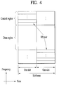
- FIG. 4 illustrates a structure of a UL subframe which may be used in embodiments of the present disclosure.
- a UL subframe may be divided into a control region and a data region in the frequency domain.
- a PUCCH carrying UCI is allocated to the control region and a PUSCH carrying user data is allocated to the data region.
- a UE does not transmit a PUCCH and a PUSCH simultaneously.
- a pair of RBs in a subframe are allocated to a PUCCH for a UE.
- the RBs of the RB pair occupy different subcarriers in two slots. Thus it is said that the RB pair frequency-hops over a slot boundary.
- FIG. 5 illustrates a structure of a DL subframe that may be used in embodiments of the present disclosure.
- DL control channels defined for the 3GPP LTE system include a Physical Control Format Indicator Channel (PCFICH), a PDCCH, and a Physical Hybrid ARQ Indicator Channel (PHICH).
- PCFICH Physical Control Format Indicator Channel
- PDCCH Physical Downlink Control Channel
- PHICH Physical Hybrid ARQ Indicator Channel
- the PCFICH is transmitted in the first OFDM symbol of a subframe, carrying information about the number of OFDM symbols used for transmission of control channels (i.e. the size of the control region) in the subframe.
- the PHICH is a response channel to a UL transmission, delivering an HARQ ACK/NACK signal.
- Control information carried on the PDCCH is called Downlink Control Information (DCI).
- the DCI transports UL resource assignment information, DL resource assignment information, or UL Transmission (Tx) power control commands for a UE group.
- a user equipment In the 3GPP LTE or LTE-A system, a user equipment (UE) is defined to report channel state information (CSI) to a base station (BS) (or eNB).
- CSI channel state information
- BS base station
- eNB eNode B
- the CSI collectively refers to information indicating the quality of a radio channel (link) established between a UE and an antenna port.
- the CSI may include a rank indicator (RI), a precoding matrix indicator (PMI), and a channel quality indicator (CQI).
- RI rank indicator
- PMI precoding matrix indicator
- CQI channel quality indicator
- the RI which indicates rank information about a channel, represents the number of streams that a UE receives through the same time-frequency resources.
- the RI value is determined depending on long-term fading of the channel and is thus usually fed back to the BS by the UE with a longer period than that for the PMI and CQI.
- the PMI which is a value reflecting the channel space characteristics, indicates a precoding index preferred by the UE based on a metric such as the SINR.
- the CQI which is a value indicating the intensity of a channel, typically indicates a reception SINR which may be obtained by the BS when the PMI is used.
- the BS configures a plurality of CSI processes for the UE and receive CSI for each process from the UE.
- the CSI process is configured with a CSI-RS for measuring the quality of the signal from the BS and CSI interference measurement (CSI-IM) resources.
- CSI-IM CSI interference measurement
- the LTE system supports radio resource management (RRM) operation including power control, scheduling, cell search, cell reselection, handover, radio link or connection monitoring, and connection establishment and re-establishment.
- RRM radio resource management
- the serving cell may request the UE to send RRM measurement information corresponding to the measurement value for performing the RRM operation.
- the UE may measure cell search information, reference signal received power (RSRP), reference signal received quality (RSRQ), and the like for each cell and then transmit the measured information.
- RSRP reference signal received power
- RSRQ reference signal received quality
- the UE receives 'measConfig' for the RRM measurement from the serving cell through a higher layer signal and then measure RSRP or RSRQ according to information in 'measConfig'.
- the RSRP, RSRQ, and RSSI has been defined as follows.
- the RSRP is defined as the linear average over the power contributions (in [W]) of the resource elements that carry cell-specific reference signals within the considered measurement frequency bandwidth.
- the cell-specific reference signals R 0 shall be used.
- the cell-specific reference signals R 0 shall be used. If the UE can reliably detect that R 1 is available, it may use R 1 in addition to R 0 to determine RSRP.
- the reference point for the RSRP shall be the antenna connector of the UE.
- the reported value shall not be lower than the corresponding RSRP of any of the individual diversity branches.
- the RSRQ is defined as the ratio N ⁇ RSRP/(E-UTRA carrier RSSI), where N is the number of RBs of the E-UTRA carrier RSSI measurement bandwidth.
- the measurements in the numerator and denominator shall be made over the same set of resource blocks.
- the E-UTRA carrier RSSI comprises the linear average of the total received power (in [W]) observed only in OFDM symbols containing reference symbols for antenna port 0, in the measurement bandwidth, over N number of resource blocks by the UE from all sources, including co-channel serving and non-serving cells, adjacent channel interference, thermal noise etc. If higher-layer signaling indicates certain subframes for performing RSRQ measurements, then RSSI is measured over all OFDM symbols in the indicated subframes.
- the reference point for the RSRQ shall be the antenna connector of the UE.
- the reported value shall not be lower than the corresponding RSRQ of any of the individual diversity branches.
- the RSSI is defined as the received wide band power, including thermal noise and noise generated in the receiver, within the bandwidth defined by the receiver pulse shaping filter.
- the reference point for the measurement shall be the antenna connector of the UE.
- the reported value shall not be lower than the corresponding UTRA carrier RSSI of any of the individual receive antenna branches.
- the UE operating in the LTE system may measure the RSRP in the bandwidth indicated by the allowed measurement bandwidth related information element (IE) transmitted in system information block type 3 (SIB3).
- the UE may measure the RSRP in the bandwidth corresponding to one of 6, 15, 25, 50, 75, 100 resource blocks (RBs) indicated by the allowed measurement bandwidth related IE transmitted in SIB5.
- the UE may measure the RSRP in the entire downlink system frequency band as the default operation.
- the UE may consider the corresponding value as the maximum measurement bandwidth and then freely measure the RSRP value in the corresponding value. However, if the service cell transmits an IE defined as WB-RSRQ to the UE and set the allowed measurement bandwidth equal to or higher than 50 RBs, the UE should calculate the RSRP value for the entire allowed measurement bandwidth. Meanwhile, when intending to the RSSI, the UE measures the RSSI using a frequency band of the UE's receiver according to the definition of RSSI bandwidth.
- MTC massive machine type communications
- the new RAT considering the enhanced mobile broadband communication, massive MTC, Ultra-reliable and low latency communication (URLLC), and the like, a new RAT system has been proposed.
- the corresponding technology is referred to as the new RAT or new radio (NR) for convenience of description.
- the NR system to which the present invention is applicable supports various OFDM numerologies shown in the following table.
- the value of ⁇ and cyclic prefix information per carrier bandwidth part can be signaled in DL and UL, respectively.
- the value of ⁇ and cyclic prefix information per downlink carrier bandwidth part may be signaled though DL-BWP-mu and DL-MWP-cp corresponding to higher layer signaling.
- the value of ⁇ and cyclic prefix information per uplink carrier bandwidth part may be signaled though UL-BWP-mu and UL-MWP-cp corresponding to higher layer signaling.
- ⁇ ⁇ f 2 ⁇ ⁇ 15 [kHz] Cyclic prefix 0 15 Normal 1 30 Normal 2 60 Normal, Extended 3 120 Normal 4 240 Normal
- Each frame may be composed of ten subframes, each having a length of 1 ms.
- each subframe may be composed of two half-frames with the same size.
- the two half-frames are composed of subframes 0 to 4 and subframes 5 to 9, respectively.
- slots may be numbered within one subframe in ascending order like n s ⁇ ⁇ 0 , ... , N slot subframe , ⁇ ⁇ 1 and may also be numbered within a frame in ascending order like n s , f ⁇ ⁇ 0 , ... , N slot frame , ⁇ ⁇ 1 .
- the number of consecutive OFDM symbols in one slot N symb slot may be determined as shown in the following table according to the cyclic prefix.
- the start slot n s ⁇ of one subframe is aligned with the start OFDM symbol n s ⁇ N symb slot of the same subframe in the time dimension.
- Table 3 shows the number of OFDM symbols in each slot/frame/subframe in the case of the normal cyclic prefix
- Table 4 shows the number of OFDM symbols in each slot/frame/subframe in the case of the extended cyclic prefix.
- [Table 3] ⁇ N symb slot N slot frame , ⁇ N slot subframe , ⁇ slot 0 14 10 1 1 14 20 2 2 14 40 4 3 14 80 8 4 14 160 16 5 14 320 32
- [Table 4] ⁇ N symb slot N slot frame , ⁇ N slot subframe , ⁇ 2 12 40 4
- a self-contained slot structure can be applied based on the above-described slot structure.
- FIG. 6 is a diagram illustrating a self-contained slot structure applicable to the present invention.
- the eNB and UE can sequentially perform DL transmission and UL transmission in one slot. That is, the eNB and UE can transmit and receive not only DL data but also UL ACK/NACK in response to the DL data in one slot. Consequently, due to such a structure, it is possible to reduce a time required until data retransmission in case a data transmission error occurs, thereby minimizing the latency of the final data transmission.
- a predetermined length of a time gap is required for the process of allowing the eNB and UE to switch from transmission mode to reception mode and vice versa.
- some OFDM symbols at the time of switching from DL to UL are set as a guard period (GP).
- the self-contained slot structure includes both the DL and UL control regions, these control regions can be selectively included in the self-contained slot structure.
- the self-contained slot structure according to the present invention may include either the DL control region or the UL control region as well as both the DL and UL control regions as shown in FIG. 6 .
- the slot may have various slot formats.
- OFDM symbols in each slot can be divided into downlink symbols (denoted by 'D'), flexible symbols (denoted by 'X'), and uplink symbols (denoted by 'U').
- the UE can assume that DL transmission occurs only in symbols denoted by 'D' and 'X' in the DL slot. Similarly, the UE can assume that UL transmission occurs only in symbols denoted by 'U' and 'X' in the UL slot.
- a millimeter wave (mmW) system since a wavelength is short, a plurality of antenna elements can be installed in the same area. That is, considering that the wavelength at 30 GHz band is 1 cm, a total of 100 antenna elements can be installed in a 5 ⁇ 5 cm panel at intervals of 0.5 lambda (wavelength) in the case of a 2-dimensional array. Therefore, in the mmW system, it is possible to improve the coverage or throughput by increasing the beamforming (BF) gain using multiple antenna elements.
- BF beamforming
- each antenna element can include a transceiver unit (TXRU) to enable adjustment of transmit power and phase per antenna element.
- TXRU transceiver unit
- hybrid BF with B TXRUs that are fewer than Q antenna elements can be considered.
- the number of beam directions that can be transmitted at the same time is limited to B or less, which depends on how B TXRUs and Q antenna elements are connected.
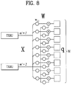
- FIGs. 7 and 8 are diagrams illustrating representative methods for connecting TXRUs to antenna elements.
- the TXRU virtualization model represents the relationship between TXRU output signals and antenna element output signals.
- FIG. 7 shows a method for connecting TXRUs to sub-arrays.
- one antenna element is connected to one TXRU.
- FIG. 8 shows a method for connecting all TXRUs to all antenna elements.
- all antenna element are connected to all TXRUs.
- separate addition units are required to connect all antenna elements to all TXRUs as shown in FIG. 8 .
- W indicates a phase vector weighted by an analog phase shifter. That is, W is a major parameter determining the direction of the analog beamforming.
- the mapping relationship between CSI-RS antenna ports and TXRUs may be 1:1 or 1-to-many.
- the configuration shown in FIG. 7 has a disadvantage in that it is difficult to achieve beamforming focusing but has an advantage in that all antennas can be configured at low cost.
- the configuration shown in FIG. 8 is advantageous in that beamforming focusing can be easily achieved.
- all antenna elements are connected to the TXRU, it has a disadvantage of high cost.
- the hybrid beamforming method obtained by combining the digital beamforming and analog beamforming can be applied.
- the analog (or radio frequency (RF)) beamforming means the operation where precoding (or combining) is performed at the RF end.
- precoding (or combining) is performed at the baseband end and RF end, respectively.
- the hybrid beamforming is advantageous in that it guarantees the performance similar to the digital beamforming while reducing the number of RF chains and D/A (digital-to-analog) (or A/D (analog-to-digital) z converters.
- the hybrid beamforming structure can be represented by N transceiver units (TXRUs) and M physical antennas.
- TXRUs transceiver units
- the digital beamforming for L data layers to be transmitted by the transmitting end may be represented by the N ⁇ L (N by L) matrix.
- N converted digital signals are converted into analog signals by the TXRUs, and then the analog beamforming, which may be represented by the M ⁇ N (M by N) matrix, is applied to the converted signals.
- FIG. 9 is a schematic diagram illustrating a hybrid beamforming structure according to an embodiment of the present invention from the perspective of TXRUs and physical antennas.
- the number of digital beams is L and the number of analog beams is N.
- a method for providing efficient beamforming to UEs located in a specific area by designing an eNB capable of changing analog beamforming on a symbol basis has been considered in the NR system to which the present invention is applicable.
- a method of introducing a plurality of antenna panels where independent hybrid beamforming can be applied by defining N TXRUs and M RF antennas as one antenna panel has also been considered in the NR system to which the present invention is applicable.
- each UE has a different analog beam suitable for signal reception.
- the beam sweeping operation where the eNB applies a different analog beam per symbol in a specific subframe (SF) (at least with respect to synchronization signals, system information, paging, etc.) and then perform signal transmission in order to allow all UEs to have reception opportunities has been considered in the NR system to which the present invention is applicable.
- SF subframe
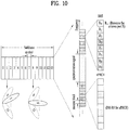
- FIG. 10 is a diagram schematically illustrating the beam sweeping operation for synchronization signals and system information during a downlink (DL) transmission process according to an embodiment of the present invention
- a physical resource (or channel) for transmitting system information of the NR system to which the present invention is applicable in a broadcasting manner is referred to as a physical broadcast channel (xPBCH).
- xPBCH physical broadcast channel
- analog beams belonging to different antenna panels can be simultaneously transmitted in one symbol.
- a beam reference signal corresponding to the reference signal (RS) to which a single analog beam (corresponding to a specific antenna panel) is applied has been discussed as the configuration for measuring a channel per analog beam in the NR system to which the present invention is applicable.
- the BRS can be defined for a plurality of antenna ports, and each BRS antenna port may correspond to a single analog beam.
- all analog beams in the analog beam group can be applied to the synchronization signal or xPBCH unlike the BRS to assist a random UE to correctly receive the synchronization signal or xPBCH.
- a primary synchronization signal (PSS) SSS, a secondary synchronization signal (SSS), and/or a physical broadcast channel (PBCH) can be transmitted within one synchronization signal (SS) block.
- PSS primary synchronization signal
- SSS secondary synchronization signal
- PBCH physical broadcast channel
- One SS burst may be composed of one or multiple SS blocks.
- the SS blocks included in one SS bust may be consecutive or not, and they may be equal to or different from each other.
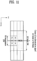
- FIG. 11 schematically illustrates the structure of an SS block applicable to the present invention.
- a PSS, SSS, and PBCH can be transmitted in four symbols.
- the PSS and SSS may be transmitted on different symbols in the same frequency band.
- the symbol in which the PSS is transmitted may be located prior to that in which the SSS is transmitted in the time domain.
- the frequency band where the PBCH is transmitted is larger than that where the PSS and SSS are transmitted, and the symbols where the PBCH is transmitted may be behind that where the PSS is transmitted.
- FIG. 11 shows that the SS block is transmitted in the following order: PSS, SSS, and PBCH, but the SS block may be transmitted in the following order: PSS, PBCH, SSS, and PBCH.
- the PBCH since the frequency band where the PBCH is transmitted is larger than that where the PSS and SSS are transmitted, the PBCH may be transmitted in the symbols where the SSS is transmitted and in the frequency band where no SSS is transmitted.
- An SS burst set may be composed of one or a plurality of SS bursts
- FIG. 12 schematically illustrates the structure where a plurality of SS bursts are transmitted within one SS block set periodicity.
- transmission of a plurality of SS bursts within one SS block set periodicity may be divided into localized type transmission and distributed type transmission.
- the SS block set periodicity one of the following values may be selected: ⁇ 5ms, 10ms, 20ms, 40ms, 80ms, and 160ms ⁇ .
- 20 ms may be used as the default SS block set periodicity value for initial cell selection.
- a UE may assume that half frames with SS blocks occur with a periodicity of 2 frames.
- a UE may perform synchronization by receiving an SS block from a gNB.
- the synchronization procedure may mainly include a cell ID detection step and a timing detection step.
- the cell ID detection step may include a PSS-based cell ID detection step and an SSS-based cell ID detection step.
- the timing detection step may include a timing detection step based on PBCH demodulation reference signals (DM-RSs) and a timing detection step based on PBCH contents (e.g., master information block (MIB)).
- DM-RSs PBCH demodulation reference signals
- MIB master information block
- the UE may obtain time synchronization and the physical cell ID of the detected cell through detection of the PSS and SSS. Specifically, the UE may obtains symbol timing for the SS block through detection of the PSS and then detect the cell ID in a cell ID group. Thereafter, the UE detects the cell ID group through detection of the SSS.
- the UE may detect the time index (e.g., slot boundary) of the SS block from a DM-RS on the PBCH. Then, the UE may obtain half-frame boundary information and system frame number (SFN) information from the MIB included in the PBCH.
- time index e.g., slot boundary
- SFN system frame number
- the present invention proposes a method by which a UE distinguishes between indices of one or more received SS blocks, determines a slot boundary (e.g., subframe boundary, frame boundary, etc.), and then transmits and receives signals with a base station based on the determined slot boundary.
- a slot boundary e.g., subframe boundary, frame boundary, etc.
- the plurality of SS/PBCH blocks may be transmitted in different (or independent) beam directions.
- the number of beams may be equal to or less than the maximum number of SS/PBCH beams in an SS/PBCH period for a particular band
- the index of the SS/PBCH block can be referred to as "SS/PBCH index” and "SS/PBCH block index”. That is, the terms “SS/PBCH index” and “SS/PBCH block index” may mean the index of a corresponding SS/PBCH block.
- SS/PBCH blocks may be indexed according to one of the following methods.
- the BS may allocate a different PBCH DM-RS sequence to each of the SS blocks.
- the PBCH DM-RS means the reference signal (RS), which is used for PBCH demodulation. In some embodiment, it may be called other names.
- the UE obtains time synchronization and the physical cell ID of a detected cell through PSS and SSS detection during the initial synchronization process.
- the UE may know not only how many SS/PBCH blocks are transmitted during the transmission period of the SS burst set before transmission of the detected SS/PBCH block but the detected SS/PBCH block is transmitted in which OFDM symbol of which slot of which frame. To this end, the UE should previously know PBCH DM-RSs used for individual SS/PBCH blocks during the transmission period of the SS burst set or which PBCH DM-RS is used for the SS/PBCH block transmitted in a certain OFDM symbol.
- the UE may match (or correlate) potential K DM-RS sequences, which may be used for the SS/PBCH blocks, with the received signal with respect to the detected cell and then check the transmitted (or received) DM-RS sequences based on the matching results. By doing so, the UE may obtain information on how many SS/PBCH blocks are transmitted before reception of the corresponding SS/PBCH blocks and/or information on frame boundaries.
- the following options may be used to distinguish between SS/PBCH block indices using PBCH DM-RSs.
- PN Pulseudo Noise
- Gold sequence is used as a generation (base) sequence for the PBCH DM-RS.
- the BS may use the PN or Gold sequence as the generation sequence for the PBCH DM-RS.
- the PN or Gold sequence generator may be initialized every OFDM symbol, and a cell ID and an OFDM symbol index may be used as the initial value.
- a slot index may also be used as the initial value.
- the BS may use the PN or Gold sequence as the generation sequence for the PBCH DM-RS.
- the PN or Gold sequence generator may be initialized every slot, and a cell ID and a slot index may be used as the initial value.
- the BS may use the PN or Gold sequence as the generation sequence for the PBCH DM-RS.
- the PN or Gold sequence generator may be initialized every block, and a cell ID and an SS/PBCH block index may be used as the initial value.
- the BS may use the PN or Gold sequence as the generation sequence for the PBCH DM-RS.
- the PN or Gold sequence generator may be initialized every SS/PBCH block, and a cell ID and an SS block index may be used as the initial value.
- the SS burst index may be transmitted to the UE.
- the SS burst may mean a unit for grouping a plurality of SS/PBCH blocks.
- the SS block index and SS burst index may respectively correspond to the first three bits and last three bits of the 6-bit information, which indicates the SS/PBCH index, according to the present invention.
- the UE may check the SS block index by matching (or correlating) the DM-RS sequences with the received signal.
- the UE may also check the SS burst index from information obtained by PBCH decoding. In this case, the UE may assume that each SS block in one SS burst contains the same PBCH information in order to perform combined decoding on the PBCH.
- the UE may partially check the SS block index and SS burst index by matching the DM-RS sequences with the received signal. Thereafter, the UE may check the complete SS burst index from the information obtained by decoding the PBCH.
- the SS block index may be the same regardless of whether the SS burst index is either an even number or odd number
- the PBCH DM-RS sequence may vary depending on whether the SS burst index is either an even number or odd number.
- a radio frame is 10 ms
- an SS burst set periodicity is 20 ms
- four SS bursts are transmitted at an interval of 5 ms.
- the BS generates a DM-RS sequence using a slot index.
- the index of the slot where the first SS burst is transmitted is different from that of the slot where the second SS burst is transmitted.
- the index of the slot where the first SS burst is transmitted is equal to that of the slot where the third SS burst is transmitted, but their subframe indices may be different from each other.
- the UE may know the SS burst detected from the PBCH is transmitted in either an even subframe or odd subframe.
- the BS may use (or apply) a different sequence for the SSS or additional SSS, which is used for each SS/PBCH block in order to distinguish between SS/PBCH blocks.
- the additional SSS may mean the SSS transmitted for the purpose of time information detection, which is attached to the SSS for cell ID detection.
- the additional SSS may be referred to as the third SS, etc.
- the UE may obtain time synchronization and the physical cell ID of a detected cell through PSS and SSS detection during the initial synchronization process. Thereafter, the UE may match sequence candidates for the SSS or additional SSS, which can be transmitted on a corresponding cell, with the received signal and then detect the SS/PBCH block index and the boundary of the SS/PBCH block set periodicity using the matching results.
- the following options may be applied to distinguish between SS/PBCH block indices using the sequence of the SSS or additional SSS.
- the BS may transmit a different sequence for the SSS or additional SSS in each SS/PBCH block.
- the BS may allocate a different PBCH DM-RS sequence per SS block of the SS burst. Accordingly, the UE can distinguish between individual SS block indices. Thereafter, the BS may allocate a different sequence for the SSS or additional SSS per SS burst, and thus, the UE can distinguish between individual SS burst indices.
- the BS may allocate a different sequence for the SSS or additional SSS per SS block of the SS burst. Accordingly, the UE can distinguish between individual SS block indices. Thereafter, may allocate a different PBCH DM-RS sequence per SS burst, and thus, the UE can distinguish between individual SS burst indices.
- the BS may allocate a different sequence for the SSS or additional SSS per SS block of the SS burst. Accordingly, the UE can distinguish between individual SS block indices. Thereafter, the BS may transmit SS burst indices to the UE via the PBCH, and the UE may perform combined decoding on the PBCH by assuming that each SS block in one SS burst contains the same PBCH information.
- the SS burst set periodicity is denoted by Ps (in most cases, 5 ms)
- the PBCH TTI is denoted by Pb (in most cases, 40 or 80 ms)
- the NR frame duration is denoted by Pf (in most cases, 10 ms).
- the BS may transmit the SS/PBCH block corresponding to an identical beam Pb/Ps times during the PBCH TTI.
- the SSS of the i-th SS/PBCH block transmitted in the PBCH TTI is denoted by SSS(i).
- SSS(i) the SSS of the i-th SS/PBCH block transmitted in the PBCH TTI.
- the BS may allocate the SSS, which is transmitted N times during the PBCH TTI, as follows.
- N SSS sequences are required for each cell. If there are a total of L physical cell IDs, the BS and UE may distinguish between cell IDs and PBCH TTI boundaries using a total of L ⁇ N SSS sequences. That is, the UE may determine the cell IDs and PBCH TTI boundaries using the IDs of the SSS sequences detected during the initial synchronization acquisition process.
- the above method may be changed to a method for allowing the UE to determine PBCH TTI boundaries.
- the BS may allocate W SSS sequences per cell and then allow the UE to distinguish between PBCH TTI boundaries based on an N-length pattern, which is obtained by combining the W sequences. For example, the BS may allocate an SSS sequence per SS/PBCH block based on a length-8 pattern (e.g., S1, S1, S1, S2, S2, S2, S3, S3) composed of three sequences (e.g., S1, S2, S3) for the SSS transmitted eight times in the PBCH TTI. In addition, the UE may check PBCH TTI boundaries using the result value obtained by matching S1, S2, and S3 with the received signal.
- a length-8 pattern e.g., S1, S1, S1, S2, S2, S2, S3, S3
- the UE may check PBCH TTI boundaries using the result value obtained by matching S1, S2, and S3 with the received signal.
- the BS may perform transmission by differently applying the generation sequence of the PBCH DM-RS in the SS/PBCH block, which is transmitted N times via the same beam during the PBCH TTI, per SS/PBCH block.
- the PN or Gold sequence may be used as the generation sequence of the PBCH DM-RS, and the PN or Gold sequence generator may be initialized every SS/PBCH block.
- a cell ID and a time index may be used as the initial value.
- the time index may be defined according to the following methods.
- Some of the OFDM symbol index, slot index, subframe index, and system frame number (SFN) may be used as the time index. For example, if the length of the PBCH TTI is a multiple of that of a frame, some of the least significant bits (LSBs) of the SFN may be used as the time index.
- LSBs least significant bits
- the SS/PBCH block index may be used as the time index.
- SS/PBCH block indices may be numbered according to how many SS/PBCH blocks are present in the PBCH TTI before a corresponding SS/PBCH block.
- the BS may generate overall PBCH DM-RSs to be used during the PBCH TTI and then divide the PBCH DM-RSs for each SS/PBCH block. That is, when the SS/PBCH block is transmitted N times via the same beam during the PBCH TTI, if a X-length DM-RS sequence is used in each SS/PBCH block, the BS may create an N ⁇ X-length DM-RS sequence at the beginning of the PBCH TTI and then divide the N ⁇ X-length DM-RS sequence into N portions.
- the BS may use the PN or Gold sequence as the DM-RS sequence, and the PN or Gold sequence generator may be initialized every PBCH TTI. In this case, only a cell ID may be configured to be used as the initial value.
- the BS may perform transmission by making coded bits of channel coding output of the PBCH in the SS/PBCH block transmitted N times via the same beam during the PBCH TTI be different from each other. That is, when the SS/PBCH block is transmitted N times during the PBCH TTI, if Y PBCH coded bits are transmitted in each SS/PBCH block, the BS may create an N ⁇ Y-length PBCH coded bit sequence and then divide the N ⁇ Y-length PBCH coded bit sequence into N portions, that is, transmit the divided sequences in each SS/PBCH block. In this case, the N ⁇ Y-length PBCH coded bit sequence may be scrambled with an N ⁇ Y-length PBCH scrambling sequence and then transmitted.
- the BS may provide, to the UE, information on some boundaries through SSS sequences and information on the remaining boundaries through PBCH DM-RS sequences.
- the BS may allocate two SSS sequences per cell and then alternately use the two sequences to enable to the UE to distinguish between 2 ⁇ Ps boundaries, which is double of the SS burst set periodicity.
- the BS may use a different PBCH DM-RS sequence in every SS/PBCH block transmitted N times via the same beam during the PBCH TTI to enable the UE to distinguish therebetween.
- the BS may divide the entire time of Pb into 2 ⁇ Ps intervals and then use a different PBCH DM-RS sequence in each of the divided intervals to enable the UE to distinguish therebetween.
- the BS may allocate four SSS sequences per cell and then alternately use the four sequences to enable to the UE to distinguish between 4 ⁇ Ps boundaries, which is quadruple of the SS burst set periodicity.
- the BS may use a different PBCH DM-RS sequence in every SS/PBCH block transmitted N times via the same beam during the PBCH TTI to enable the UE to distinguish therebetween.
- the BS may divide the entire time of Pb into 2 ⁇ Ps or 4 ⁇ Ps intervals and then use a different PBCH DM-RS sequence in each of the divided intervals (N/2 or N/4) to enable the UE to distinguish therebetween.
- the BS may provide, to the UE, information on some boundaries through SSS sequences and information on the remaining boundaries through PBCH RVs.
- the BS may allocate two SSS sequences per cell and then alternately use the two sequences to enable to the UE to distinguish between 2 ⁇ Ps boundaries, which is double of the SS burst set periodicity.
- the BS may allocate four SSS sequences per cell and then alternately use the four sequences to enable to the UE to distinguish between 4 ⁇ Ps boundaries, which is quadruple of the SS burst set periodicity.
- the BS may provide, to the UE, information on some boundaries through PBCH DM-RS sequences and information on the remaining boundaries through PBCH RVs.
- the BS may allocate two PBCH DM-RS sequences per cell and then alternately use the two sequences to enable to the UE to distinguish between 2 ⁇ Ps boundaries, which is double of the SS burst set periodicity.
- the BS may allocate four PBCH DM-RS sequences per cell and then alternately use the four sequences to enable to the UE to distinguish between 4 ⁇ Ps boundaries, which is quadruple of the SS burst set periodicity.
- the BS may provide, to the UE, information on some boundaries through SSS sequences, information on some remaining boundaries through PBCH DM-RS sequences, and information on the remaining boundaries through PBCH RVs.
- the BS may allocate two SSS sequences per cell and then alternately use the two sequences to enable to the UE to distinguish between 2 ⁇ Ps boundaries, which is double of the SS burst set periodicity.
- the BS may allocate four PBCH DM-RS sequences per cell and then alternately use the four sequences to enable to the UE to distinguish between 4 ⁇ Ps boundaries, which is quadruple of the SS burst set periodicity.
- the PBCH TTI may be determined according to one of the following methods. For example, if the SS burst set periodicity is set to one of the following values: ⁇ 5ms, 10 ms, 20 ms, 40 ms, 80ms ⁇ , the PBCH TTI may be determined according to the following options.
- Opt 1 The PBCH TTI is consistently maintained at all times.
- the PBCH TTI may be configured to be always maintained at the same level regardless of the SS burst set periodicity.
- the PBCH TTI may be fixed to the maximum value among values that can be used as the SS burst set periodicity.
- the SS burst set periodicity is set to be one of the following values: ⁇ 5ms, 10 ms, 20 ms, 40 ms, 80ms ⁇
- the PBCH may be set to the maximum value, 80 ms.
- the number of times that the PBCH is transmitted during the PBCH TTI may be set to one of the following values: ⁇ 16, 8, 4, 2, 1 ⁇ according to the configured SS burst set periodicity.
- the PBCH TTI may be fixed to one of the values that can be used as the SS burst set periodicity.
- the SS burst set periodicity is set to be one of the following values: ⁇ 5ms, 10 ms, 20 ms, 40 ms, 80ms ⁇
- the PBCH may be set to 40 ms.
- the PBCH may not be transmitted during the PBCH TTI.
- the PBCH may be transmitted at one time during one TTI among continuous PBCH TTIs.
- the number of times that the PBCH is transmitted during the PBCH TTI may be fixed regardless of the SS burst set periodicity.
- the ratio between the SS burst set periodicity and PBCH TTI may be fixed.
- the PBCH TTI, Pb may be set to N ⁇ Ps.
- the PBCH may be transmitted N times during the PBCH TTI regardless of the configured SS burst set periodicity.
- Pb may be limited to a specific range.
- the master system information (MIB), which is transmitted via the PBCH may include SFN information to inform the UE of system frame timing.
- the BS may inform the UE of the common part of SFNs of radio frames included in the PBCH TTI (i.e., the most significant bits (MSBs) of the SFNs) to minimize the information amount.
- MSBs most significant bits
- the BS may inform the UE of only MSBs of the SFN except 2-bit LSBs.
- the length of an SFN information field included in the MIB may be designed according to the following methods. In the following description, it is assumed that a radio frame is 10 ms and an SFN is represented by (L) bits.
- the length of the SFN information filed may be configured to vary according to the configured PBCH TTI. For example, assuming that the ratio between the PBCH TTI and radio frame is R, only upper L-log 2 (R) bits of the SFN in the MIB are transmitted, and thus the SFN information field may be configured to have a corresponding length.
- the total length of the MIB may also vary.
- the UE already knows the PBCH TTI using other methods. Accordingly, the UE determines the total length of the MIB and then performs the PBCH decoding according to the total length of the MIB.
- the length of reserved bits may be configured to vary such that when the length of the SFN information field varies, the total length of the MIB length is not changed. In other words, the total MIB length may not be changed by fixing the sum of the SFN information field length and reserved-bit length to a certain value. In this case, even though the UE does not obtain the PBCH TTI before PBCH decoding, the UE may perform the PBCH decoding. Thus, the PBCH TTI or SS burst set periodicity information may be transmitted together with the MIB.
- the length of the SFN information field may be set to a specific value which is required when the PBCH TTI has the minimum value. For example, assuming the ratio between the minimum PBCH TTI and radio frame is R_min, the SFN of the MIB may be set using upper L-log 2 (R_min) bits.
- the BS may inform the UE of the SFN of the first radio frame in the PBCH TTI as it is, that is, (L) bits without decreasing it.
- the UE may detect a neighboring cell through SSS detection and then report the results of measuring the average reception level of SSSs without any additional verification process to the BS via layer 3 to assist handover determination.
- the number of times that a virtual cell is falsely detected due to errors should be minimized.
- the false SSS detection may frequently occur if the correlation characteristics between two cells' SSS sequences is poor. For example, assuming that that a normalized correlation value between an SSS transmitted from the a-th cell (denoted by SSS a ) and an SSS transmitted from the b-th cell (denoted by SSS b ) is more than 05, if SSS a is detected, the UE may determine that SSS b , which is weaker than SSS a by 3 dB, has been detected together.
- a method for changing the SSS used in each cell depending on time may be used.
- the SSSs used in one cell when SSSs used in one cell are used cyclically according to the PBCH TTI, the SSSs used in the corresponding cell may be changed depending on time.
- the circulation cycle of the SSS may be defined as a multiple of the PBCH TTI or SS burst set periodicity.
- the BS may design the pattern of SSSa(i) for L cells using only L or c ⁇ L (c ⁇ N) sequences. This method can be expressed according to the following equation.
- the final cell ID may be finally confirmed by the SS burst set periodicity boundary and the detected SSS sequence pattern.
- L' indicates a prim number more than L.
- the BS may generate and use L' as the SSS sequence.
- the sequence using L SSS sequences is used, if a generated index is more than L, the generated index is discarded, and the time index i additionally increases.
- FIG. 13 illustrates a method for transmitting and receiving signals between a UE and a BS applicable to the present invention.
- the BS 100 generates at least one synchronization signal/physical broadcast channel (SS/PBCH) block to be transmitted [S1310].
- SS/PBCH synchronization signal/physical broadcast channel
- the BS 100 may generate each SS/PBCH block such that it contains the PSS, SSS, and PBCH corresponding thereto.
- the BS 100 may generate each SS/PBCH block such that a DM-RS sequence for a PBCH per SS/PBCH block indicates the index of each SS/PBCH block or a combination of the DM-RS sequence for the PBCH per SS/PBCH block and information included in the PBCH per SS/PBCH block indicates the index of each SS/PBCH block.
- the BS 100 may generate the DM-RS sequence for the PBCH included in each SS/PBCH block using a cell identifier (ID) and each SS/PBCH block index.
- ID cell identifier
- the DM-RS sequence for the PBCH included in each SS/PBCH block may be generalized using a Gold sequence.
- the BS 100 transmits the at least one SS/PBCH block [S1320]. Specifically, the BS 100 may transmits a plurality of SS/PBCH blocks as shown in FIG. 12 . For example, the BS 100 may transmit each SS/PBCH block via an independent (or different) beam. Accordingly, from the perspective of a specific UE (1), one SS/PBCH block among the plurality of SS/PBCH blocks may be received, or the signal strength of an SS/PBCH block may be high and that of another SS/PBCH block may be low.
- a transmission time interval (TTI) of the PBCH included in the SS/PBCH block may be set to 80 ms.
- the PBCH included in each SS/PBCH block may carry the same information during the 80 ms.
- the UE 1 may receive some or all of the one or more SS/PBCH blocks.
- the UE 1 detects the received SS/PBCH block [S1330]. Specifically, the UE may detect the index of the received SS/PBCH block based on a DM-RS sequence for the PBCH included in the received SS/PBCH block (or a combination of the sequence and information included in the PBCH. By doing so, the UE 1 may detect the index (or location) of the received SS/PBCH block among the plurality of SS/PBCH blocks shown in FIG. 12 .
- the UE 1 may obtain time synchronization and a cell identifier (ID) based on the PSS and SSS included in the SS/PBCH block.
- ID cell identifier
- the UE 1 may achieve synchronization with the BS 100 and transmit and receive signals with the BS 100 [S1340].
- the BS 100 may transmit SS/PBCH blocks in independent beam directions.
- the UE 1 may detect the index of the received SS/PBCH block based on the DM-RS sequence for the PBCH included in the received SS/PBCH block (or the combination of the sequence and the information included in the PBCH), detect the slot boundary (e.g., subframe boundary, half frame boundary, frame boundary, etc.), and then achieve the synchronization with the BS 100.
- the slot boundary e.g., subframe boundary, half frame boundary, frame boundary, etc.
- each of the embodiments of the above-described proposed methods may be considered as one method for implementing the present invention, it is apparent that each embodiment can be regarded as a proposed method.
- the present invention can be implemented not only using the proposed methods independently but also by combining (or merging) some of the proposed methods.
- a rule may be defined such that the BS should inform the UE of information on whether the proposed methods are applied (or information on rules related to the proposed methods) through a predefined signal (e.g., physical layer signal, higher layer signal, etc.).
- FIG. 14 is a diagram illustrating configurations of a UE and a BS capable of being implemented by the embodiments proposed in the present invention.
- the UE and BS illustrated in FIG. 14 operate to implement the above-described embodiments of the method for transmitting and receiving signals therebetween.
- the UE 1 may act as a transmission end on UL and as a reception end on DL.
- the BS (eNB or gNB) 100 may act as a reception end on UL and as a transmission end on DL.
- each of the UE and the BS may include a Transmitter (Tx) 10 or 110 and a Receiver (Rx) 20 or 120, for controlling transmission and reception of information, data, and/or messages, and an antenna 30 or 130 for transmitting and receiving information, data, and/or messages.
- Tx Transmitter
- Rx Receiver
- Each of the UE and the base station may further include a processor 40 or 140 for implementing the afore-described embodiments of the present disclosure and a memory 50 or 150 for temporarily or permanently storing operations of the processor 40 or 140.
- the UE 1 receives a synchronization signal/physical broadcast channel (SS/PBCH) block from the BS 100 through the receiver 20.
- the UE 1 determines the index of the received SS/PBCH block based on a demodulation reference signal (DM-RS) sequence for a PBCH included in the SS/PBCH block or a combination of the sequence and information included in the PBCH through the processor 40.
- DM-RS demodulation reference signal
- the UE 1 performs synchronization with the BS 100 based on the determined SS/PBCH block index through the transmitter 10 and receiver 20.
- the BS 100 transmits at least one synchronization signal/physical broadcast channel (SS/PBCH) block through the transmitter 110.
- SS/PBCH synchronization signal/physical broadcast channel
- DM-RS demodulation reference signal
- the BS 100 transmits and receives signals with the UE that performs synchronization with the BS 100 based on the at least one SS/PBCH block through the transmitter 110 and receiver 120.
- the Tx and Rx of the UE and the base station may perform a packet modulation/demodulation function for data transmission, a high-speed packet channel coding function, OFDM packet scheduling, TDD packet scheduling, and/or channelization.
- Each of the UE and the base station of FIG. 14 may further include a low-power Radio Frequency (RF)/Intermediate Frequency (IF) module.
- RF Radio Frequency
- IF Intermediate Frequency
- the UE may be any of a Personal Digital Assistant (PDA), a cellular phone, a Personal Communication Service (PCS) phone, a Global System for Mobile (GSM) phone, a Wideband Code Division Multiple Access (WCDMA) phone, a Mobile Broadband System (MBS) phone, a hand-held PC, a laptop PC, a smart phone, a Multi Mode-Multi Band (MM-MB) terminal, etc.
- PDA Personal Digital Assistant
- PCS Personal Communication Service
- GSM Global System for Mobile
- WCDMA Wideband Code Division Multiple Access
- MBS Mobile Broadband System
- hand-held PC a laptop PC
- smart phone a Multi Mode-Multi Band (MM-MB) terminal, etc.
- MM-MB Multi Mode-Multi Band
- the smart phone is a terminal taking the advantages of both a mobile phone and a PDA. It incorporates the functions of a PDA, that is, scheduling and data communications such as fax transmission and reception and Internet connection into a mobile phone.
- the MB-MM terminal refers to a terminal which has a multi-modem chip built therein and which can operate in any of a mobile Internet system and other mobile communication systems (e.g. CDMA 2000, WCDMA, etc.).
- Embodiments of the present disclosure may be achieved by various means, for example, hardware, firmware, software, or a combination thereof.
- the methods according to exemplary embodiments of the present disclosure may be achieved by one or more Application Specific Integrated Circuits (ASICs), Digital Signal Processors (DSPs), Digital Signal Processing Devices (DSPDs), Programmable Logic Devices (PLDs), Field Programmable Gate Arrays (FPGAs), processors, controllers, microcontrollers, microprocessors, etc.
- ASICs Application Specific Integrated Circuits
- DSPs Digital Signal Processors
- DSPDs Digital Signal Processing Devices
- PLDs Programmable Logic Devices
- FPGAs Field Programmable Gate Arrays
- processors controllers, microcontrollers, microprocessors, etc.
- the methods according to the embodiments of the present disclosure may be implemented in the form of a module, a procedure, a function, etc. performing the above-described functions or operations.
- a software code may be stored in the memory 50 or 150 and executed by the processor 40 or 140.
- the memory is located at the interior or exterior of the processor and may transmit and receive data to and from the processor via various known means.
- the present disclosure is applicable to various wireless access systems including a 3GPP system, and/or a 3GPP2 system. Besides these wireless access systems, the embodiments of the present disclosure are applicable to all technical fields in which the wireless access systems find their applications. Moreover, the proposed method can also be applied to mmWave communication using an ultra-high frequency band.
Landscapes
- Engineering & Computer Science (AREA)
- Computer Networks & Wireless Communication (AREA)
- Signal Processing (AREA)
- Databases & Information Systems (AREA)
- Computer Security & Cryptography (AREA)
- Mobile Radio Communication Systems (AREA)
Claims (11)
- Procédé destiné à transmettre et à recevoir des signaux vers et depuis une station de base, BS, par un équipement utilisateur, UE, dans un système de communication sans fil, le procédé comprenant :la réception d'un bloc de signal de synchronisation/canal de diffusion physique, SS/PBCH, en provenance de la BS ;la détermination d'un indice du bloc SS/PBCH reçu sur la base i) d'une séquence d'un signal de référence de démodulation, DM-RS, pour un PBCH contenu dans le bloc SS/PBCH ou ii) d'une combinaison de la séquence DM-RS pour le PBCH et d'informations contenues dans Le PBCH; etdans lequel la séquence DM-RS pour le PBCH est initialisée dans une unité du bloc SS/PDCCH, sur la base d'une valeur initiale déterminée sur la base d'un identifiant de cellule, ID de cellule, et de l'indice du bloc SS/PBCH, etla réalisation d'une synchronisation avec la BS sur la base de l'indice déterminé du bloc SS/PBCH.
- Procédé selon la revendication 1, dans lequel le bloc SS/PBCH comprend en outre un signal de synchronisation primaire, PSS, et un signal de synchronisation secondaire, SSS.
- Procédé selon la revendication 2, comprenant en outre l'étape consistant à obtenir une synchronisation temporelle et l'ID de cellule sur la base du PSS et du SSS.
- Procédé selon la revendication 3, dans lequel une séquence de Gold est utilisée en tant que séquence DM-RS.
- Procédé selon la revendication 1, dans lequel le PBCH présente un intervalle de temps de transmission, TTI, de 80 ms.
- Procédé destiné à transmettre et à recevoir des signaux vers et depuis un équipement utilisateur, UE, par une station de base, BS, dans un système de communication sans fil, le procédé comprenant :la transmission d'au moins un bloc de signal de synchronisation/canal de diffusion physique, SS/PBCH,dans lequel i) une séquence de signal de référence de démodulation, DM-RS, pour un PBCH contenu dans chaque bloc SS/PBCH ou ii) une combinaison de la séquence DM-RS pour le PBCH et d'informations contenues dans le PBCH indique un indice de chaque bloc SS/PBCH, etdans lequel la séquence DM-RS pour le PBCH est initialisée dans une unité du bloc SS/PBCH, sur la base d'une valeur initiale déterminée sur la base d'un identifiant de cellule, ID de cellule, et de l'indice du bloc SS/PBCH, etla transmission et la réception de signaux vers et depuis l'UE qui réalise une synchronisation avec la BS sur la base du au moins un bloc SS/PBCH.
- Procédé selon la revendication 6, dans lequel le au moins un bloc SS/PBCH est transmis via un faisceau indépendant.
- Procédé selon la revendication 6, dans lequel le bloc SS/PBCH comprend en outre un signal de synchronisation primaire, PSS, et un signal de synchronisation secondaire, SSS.
- Procédé selon la revendication 8, dans lequel la séquence DM-RS pour le PBCH contenu dans chaque bloc SS/PBCH correspond à une séquence de Gold basée sur l'ID de cellule et chaque indice de bloc SS/PBCH.
- Équipement utilisateur, UE, destiné à transmettre et à recevoir des signaux vers et depuis une station de base, BS, dans un système de communication sans fil, l'UE comprenant :un émetteur ;un récepteur ; etun processeur connecté à l'émetteur et au récepteur,dans lequel le processeur est configuré pour :recevoir un bloc de signal de synchronisation/canal de diffusion physique, SS/PBCH, en provenance de la BS ;déterminer un indice du bloc SS/PBCH reçu sur la base i) d'une séquence d'un signal de référence de démodulation, DM-RS, pour un PBCH contenu dans le bloc SS/PBCH ou ii) d'une combinaison de la séquence DM-RS pour le PBCH et d'informations contenues dans le PBCH ; etdans lequel la séquence DM-RS pour le PBCH est initialisée dans une unité du bloc SS/PBCH, sur la base d'une valeur initiale déterminée sur la base d'un identifiant de cellule, ID de cellule, et de l'indice du bloc SS/PBCH, etréaliser une synchronisation avec la BS sur la base de l'indice déterminé du bloc SS/PBCH.
- Station de base, BS, destinée à transmettre et à recevoir des signaux vers et depuis un équipement utilisateur, UE, dans un système de communication sans fil, la BS comprenant :un émetteur ;un récepteur ; etun processeur connecté à l'émetteur et au récepteur,dans lequel le processeur est configuré pour :transmettre au moins un bloc de signal de synchronisation/canal de diffusion physique, SS/PBCH,dans lequel i) une séquence d'un signal de référence de démodulation, DM-RS, pour un PBCH contenu dans chaque bloc SS/PBCH ou ii) une combinaison de la séquence DM-RS pour le PBCH et d'informations contenues dans le PBCH indique un indice de chaque bloc SS/PBCH, etdans lequel la séquence DM-RS pour le PBCH est initialisée dans une unité du bloc SS/PBCH, sur la base d'une valeur initiale déterminée sur la base d'un identifiant de cellule, ID de cellule, et de l'indice du bloc SS/PBCH, ettransmettre et recevoir des signaux vers et depuis l'UE qui réalise une synchronisation avec la BS sur la base du au moins un bloc SS/PBCH.
Applications Claiming Priority (3)
| Application Number | Priority Date | Filing Date | Title |
|---|---|---|---|
| US201762455544P | 2017-02-06 | 2017-02-06 | |
| US201762472505P | 2017-03-16 | 2017-03-16 | |
| PCT/KR2018/001576 WO2018143771A1 (fr) | 2017-02-06 | 2018-02-06 | Procédé d'émission et de réception de signaux entre un terminal et une station de base dans un système de communication sans fil, et appareil pour prendre en charge celui-ci |
Publications (3)
| Publication Number | Publication Date |
|---|---|
| EP3402100A1 EP3402100A1 (fr) | 2018-11-14 |
| EP3402100A4 EP3402100A4 (fr) | 2019-12-04 |
| EP3402100B1 true EP3402100B1 (fr) | 2021-03-31 |
Family
ID=63040902
Family Applications (1)
| Application Number | Title | Priority Date | Filing Date |
|---|---|---|---|
| EP18746559.6A Active EP3402100B1 (fr) | 2017-02-06 | 2018-02-06 | Procédé d'émission et de réception de signaux entre un terminal et une station de base dans un système de communication sans fil, et appareil pour prendre en charge celui-ci |
Country Status (6)
| Country | Link |
|---|---|
| US (4) | US10440672B2 (fr) |
| EP (1) | EP3402100B1 (fr) |
| JP (1) | JP6804641B2 (fr) |
| KR (1) | KR101988325B1 (fr) |
| CN (2) | CN112039813B (fr) |
| WO (1) | WO2018143771A1 (fr) |
Families Citing this family (37)
| Publication number | Priority date | Publication date | Assignee | Title |
|---|---|---|---|---|
| WO2018058464A1 (fr) * | 2016-09-29 | 2018-04-05 | 广东欧珀移动通信有限公司 | Procédé de transmission de signal, dispositif terminal et dispositif de réseau |
| US10470191B2 (en) | 2016-12-09 | 2019-11-05 | Samsung Electronics Co., Ltd. | Method and apparatus of broadcast signals and channels for system information transmission |
| KR101988325B1 (ko) | 2017-02-06 | 2019-06-12 | 엘지전자 주식회사 | 무선 통신 시스템에서 단말과 기지국간 신호 송수신 방법 및 이를 지원하는 장치 |
| WO2018147645A1 (fr) * | 2017-02-07 | 2018-08-16 | Innovative Technology Lab Co., Ltd. | Procédé et appareil de configuration de canal de diffusion et transmission et de réception de canal de diffusion pour système de communication |
| JP7028883B2 (ja) * | 2017-02-16 | 2022-03-02 | エルジー エレクトロニクス インコーポレイティド | 非免許帯域を支援する無線通信システムにおいて基地局と端末の間の信号送受信方法及びそれを支援する装置 |
| US10484153B2 (en) * | 2017-03-09 | 2019-11-19 | Samsung Electronics Co., Ltd. | Method and apparatus for NR-DMRS sequence design |
| RU2734100C1 (ru) * | 2017-03-15 | 2020-10-13 | Гуандун Оппо Мобайл Телекоммьюникейшнс Корп., Лтд. | Способ передачи сигнала, оконечное устройство и сетевое устройство |
| KR20180107686A (ko) * | 2017-03-22 | 2018-10-02 | 삼성전자주식회사 | 무선 셀룰라 통신 시스템에서 상향 제어 채널 전송 방법 및 장치 |
| EP3602826A1 (fr) | 2017-03-23 | 2020-02-05 | Convida Wireless, LLC | Apprentissage de faisceau et accès initial |
| CN108631982B (zh) * | 2017-03-24 | 2021-07-20 | 展讯通信(上海)有限公司 | 5g系统中同步信号块的发送方法、接收方法及装置 |
| EP3605957B1 (fr) * | 2017-03-28 | 2022-03-09 | Beijing Xiaomi Mobile Software Co., Ltd. | Procédé et dispositif de transmission et d'acquisition de bloc d'informations de synchronisation |
| CN108809568B (zh) | 2017-05-04 | 2023-11-03 | 华为技术有限公司 | 一种信息发送、接收方法及相关设备 |
| WO2018201475A1 (fr) * | 2017-05-05 | 2018-11-08 | 富士通株式会社 | Procédé d'indication d'informations, procédé et dispositif de détection associés, et système de communication |
| CN112566238B (zh) | 2017-05-05 | 2022-03-01 | 中兴通讯股份有限公司 | 用于传送同步信号定时信息的技术 |
| US11252683B2 (en) * | 2017-06-15 | 2022-02-15 | Ntt Docomo, Inc. | User terminal and radio communication method |
| US11304157B2 (en) * | 2017-06-21 | 2022-04-12 | Apple Inc. | Collision handling of synchronization signal (SS) blocks |
| US20190013917A1 (en) * | 2017-07-10 | 2019-01-10 | Qualcomm Incorporated | Demodulation reference signal (dmrs) sequence generation and resource mapping for physical broadcast channel (pbch) transmissions |
| CN109309552B (zh) * | 2017-07-26 | 2021-02-26 | 维沃移动通信有限公司 | 物理广播信道的dmrs传输方法、网络设备及终端 |
| CN111165008B (zh) * | 2017-08-08 | 2024-04-05 | 苹果公司 | 用于新无线电系统的新的基于质量的测量定义 |
| US11212762B2 (en) * | 2017-08-11 | 2021-12-28 | Nec Corporation | Methods and apparatuses for synchronization signal transmission |
| US11856540B2 (en) | 2020-02-10 | 2023-12-26 | Nec Corporation | Methods and apparatuses for synchronization signal transmission |
| CN109428695B (zh) * | 2017-08-24 | 2020-10-09 | 电信科学技术研究院 | 一种测量间隙确定方法、用户终端和网络侧设备 |
| WO2019066712A1 (fr) * | 2017-09-28 | 2019-04-04 | Telefonaktiebolaget Lm Ericsson (Publ) | Rapport de mesure flexible dans des scénarios à technologies d'accès radio multiples |
| WO2019098786A1 (fr) * | 2017-11-17 | 2019-05-23 | Lg Electronics Inc. | Procédé et appareil d'exécution de mesurage dans un système de communication sans fil |
| US10880864B2 (en) * | 2018-02-22 | 2020-12-29 | Qualcomm Incorporated | Methods and apparatuses for waveform indication in high-frequency bands |
| CN114070542B (zh) * | 2018-08-10 | 2024-12-13 | 北京小米移动软件有限公司 | 发送、接收参考信号的方法、装置、车载设备及终端 |
| US11985612B2 (en) * | 2018-09-20 | 2024-05-14 | Electronics And Telecommunications Research Institute | Method and apparatus for transmitting and receiving signal including cell information in communication system |
| WO2020060355A1 (fr) * | 2018-09-21 | 2020-03-26 | 엘지전자 주식회사 | Procédé et dispositif de réduction de consommation d'énergie pendant la mesure dans un système de communication sans fil |
| CN111245537B (zh) * | 2018-11-29 | 2021-06-01 | 华为技术有限公司 | 一种测量方法及装置 |
| KR102785896B1 (ko) | 2018-12-31 | 2025-03-25 | 삼성전자주식회사 | 빔포밍에 기반한 통신을 수행하는 전자 장치 및 이를 위한 방법 |
| WO2020142513A1 (fr) * | 2019-01-02 | 2020-07-09 | Idac Holdings, Inc. | Dmrs à faible papr et faible interférence inter-cellule d'ofdm à étalement de dft |
| WO2020145751A1 (fr) | 2019-01-11 | 2020-07-16 | 엘지전자 주식회사 | Procédé d'émission ou de réception de bloc de signaux de synchronisation dans une bande sans licence et appareil associé |
| EP3917192A1 (fr) * | 2019-01-23 | 2021-12-01 | Ntt Docomo, Inc. | Terminal d'utilisateur et procédé de communication sans fil |
| CN111586746B (zh) * | 2019-02-15 | 2022-01-14 | 华为技术有限公司 | 配置信息的方法和装置 |
| CN110140301B (zh) * | 2019-03-25 | 2023-06-27 | 北京小米移动软件有限公司 | 同步信号块传输方法、装置及存储介质 |
| CN110519838B (zh) * | 2019-08-06 | 2021-07-13 | 三维通信股份有限公司 | 分布式天线系统的时分双工同步方法、装置、设备和介质 |
| CN120434085A (zh) * | 2024-02-04 | 2025-08-05 | 华为技术有限公司 | 一种通信方法及装置 |
Family Cites Families (45)
| Publication number | Priority date | Publication date | Assignee | Title |
|---|---|---|---|---|
| KR101253197B1 (ko) * | 2010-03-26 | 2013-04-10 | 엘지전자 주식회사 | 참조신호 수신 방법 및 사용자기기, 참조신호 전송 방법 및 기지국 |
| US10638464B2 (en) * | 2011-04-01 | 2020-04-28 | Futurewei Technologies, Inc. | System and method for transmission and reception of control channels in a communications system |
| US8369280B2 (en) * | 2011-07-01 | 2013-02-05 | Ofinno Techologies, LLC | Control channels in multicarrier OFDM transmission |
| US8582527B2 (en) * | 2011-07-01 | 2013-11-12 | Ofinno Technologies, Llc | Hybrid automatic repeat request in multicarrier systems |
| US9350397B2 (en) * | 2011-07-27 | 2016-05-24 | Lg Electronics Inc. | Method for transmitting an uplink reference signal in a multi-node system and terminal using same |
| KR102058999B1 (ko) * | 2012-02-21 | 2019-12-24 | 엘지전자 주식회사 | 무선 통신 시스템에서 초기 접속 방법 및 장치 |
| US9490943B2 (en) * | 2012-02-21 | 2016-11-08 | Lg Electronics Inc. | Method for receiving or transmitting downlink signal and apparatus for same |
| US9497756B2 (en) * | 2012-03-25 | 2016-11-15 | Comcast Cable Communications, Llc | Base station radio resource management |
| US8923207B2 (en) * | 2012-05-17 | 2014-12-30 | Industrial Technology Research Institute | Method for initializing sequence of reference signal and base station using the same |
| WO2014042373A1 (fr) * | 2012-09-16 | 2014-03-20 | 엘지전자 주식회사 | Procédé de réception ou de transmission d'un signal de diffusion dans un système de communication sans fil et appareil pour ce procédé |
| EP2901640A2 (fr) * | 2012-09-26 | 2015-08-05 | Interdigital Patent Holdings, Inc. | Procédés, systèmes et appareils pour fonctionnement dans des systèmes d'évolution à long terme (lte) |
| WO2014069945A1 (fr) | 2012-11-01 | 2014-05-08 | 엘지전자 주식회사 | Procédé et appareil d'émission-réception de signal de référence dans un système de communication sans fil |
| CN103813468A (zh) * | 2012-11-09 | 2014-05-21 | 北京三星通信技术研究有限公司 | 一种传输下行数据的方法和设备 |
| KR20140080296A (ko) * | 2012-12-20 | 2014-06-30 | 주식회사 팬택 | 단말, 단말의 정보 수신 방법, 기지국, 및 기지국의 정보 전송 방법 |
| CN103906139B (zh) * | 2012-12-27 | 2018-10-30 | 夏普株式会社 | 系统信息的发送和接收方法以及基站和用户设备 |
| US9756656B2 (en) * | 2013-01-09 | 2017-09-05 | Lg Electronics Inc. | Method and user equipment for receiving signal and method and base station for transmitting signal |
| JP6320511B2 (ja) * | 2013-03-21 | 2018-05-09 | エルジー エレクトロニクス インコーポレイティド | 放送チャネル方法、放送チャネル信号送受信方法、及びこれらを支援する装置 |
| CN104104640B (zh) * | 2013-04-02 | 2017-12-29 | 宏碁股份有限公司 | 通讯站及通讯装置 |
| KR20140120173A (ko) | 2013-04-02 | 2014-10-13 | 주식회사 팬택 | Nct에 기반한 무선 통신 시스템에서 제어채널의 구성정보를 획득하는 장치 및 방법 |
| CN104104636B (zh) * | 2013-04-02 | 2017-08-25 | 上海贝尔股份有限公司 | 为基于dm‑rs解调的pbch配置物理资源的方法 |
| EP2982189B1 (fr) * | 2013-04-03 | 2017-12-27 | Google Technology Holdings LLC | Procédés et dispositif de recherche de cellule |
| US9893854B2 (en) * | 2013-09-20 | 2018-02-13 | Qualcomm Incorporated | Sequence mapping for LTE/LTE-A with unlicensed spectrum |
| US9510208B2 (en) * | 2013-10-04 | 2016-11-29 | Qualcomm Incorporated | Sequence generation for shared spectrum |
| EP3065448B1 (fr) * | 2013-11-01 | 2018-12-05 | Sharp Kabushiki Kaisha | Dispositif terminal, dispositif station de base et procédé associé |
| WO2015068602A1 (fr) * | 2013-11-08 | 2015-05-14 | シャープ株式会社 | Dispositif terminal, dispositif station de base, procédé de communication, et circuit intégré |
| CA2931656C (fr) * | 2013-11-26 | 2022-07-19 | Sharp Kabushiki Kaisha | Dispositif de terminal, dispositif de station de base, procede de communication et circuit integre |
| JP2017085188A (ja) * | 2014-03-13 | 2017-05-18 | シャープ株式会社 | 端末装置、基地局装置および通信方法 |
| CN105229936B (zh) * | 2014-03-18 | 2019-05-28 | 华为技术有限公司 | 网络侦听方法及设备 |
| KR101612516B1 (ko) | 2014-07-24 | 2016-04-29 | 최도현 | 건식 및 습식 처리를 위한 단일 플랫폼의 기판처리설비 |
| JP6592445B2 (ja) * | 2014-09-03 | 2019-10-16 | シャープ株式会社 | 端末、および、基地局 |
| CN106688292B (zh) * | 2014-09-10 | 2020-05-15 | 夏普株式会社 | 终端、基站以及通信方法 |
| EP4475622A3 (fr) * | 2014-09-24 | 2025-03-12 | InterDigital Patent Holdings, Inc. | Indication d'utilisation de canal et synchronisation pour fonctionnement lte dans des bandes sans licence |
| US10171220B2 (en) * | 2014-10-17 | 2019-01-01 | Sharp Kabushiki Kaisha | Terminal, base station, and communication method |
| WO2016072495A1 (fr) * | 2014-11-06 | 2016-05-12 | シャープ株式会社 | Dispositif terminal, dispositif de station de base et procédé |
| US10548039B2 (en) | 2014-12-05 | 2020-01-28 | Lg Electronics Inc. | Method and device for selecting cell in wireless communication system |
| KR20160121367A (ko) | 2015-04-10 | 2016-10-19 | 주식회사 아이티엘 | 다차원 다중 안테나 시스템에서 참조 신호의 전송 장치 및 방법 |
| KR102373038B1 (ko) | 2015-05-06 | 2022-03-11 | 삼성전자 주식회사 | 기기 대 기기 무선 통신에서 신호 수신 방법 및 장치 |
| KR20160134367A (ko) * | 2015-05-15 | 2016-11-23 | 주식회사 아이티엘 | 단말간 직접 통신에서 단말과 네트워크 간 릴레이 구성 방법 및 장치 |
| US10849170B2 (en) * | 2015-10-08 | 2020-11-24 | Apple Inc. | Signaling methods for flexible radio resource management |
| US11382081B2 (en) * | 2015-10-16 | 2022-07-05 | Samsung Electronics Co., Ltd. | Method and apparatus for system information acquisition in wireless communication system |
| JP2019004194A (ja) * | 2015-11-05 | 2019-01-10 | シャープ株式会社 | 端末装置、基地局装置および方法 |
| US11570597B2 (en) * | 2016-02-08 | 2023-01-31 | Qualcomm Incorporated | Pilot design for uplink (UL) narrow-band internet of things (NB-IoT) |
| EP3563621A1 (fr) * | 2016-12-28 | 2019-11-06 | Nokia Technologies Oy | Récupération de la configuration d'une connexion pour réseaux sans fil |
| KR101988325B1 (ko) | 2017-02-06 | 2019-06-12 | 엘지전자 주식회사 | 무선 통신 시스템에서 단말과 기지국간 신호 송수신 방법 및 이를 지원하는 장치 |
| MX2021003254A (es) * | 2018-09-21 | 2021-05-12 | Ntt Docomo Inc | Terminal de usuario y comunicacion por radio. |
-
2018
- 2018-02-06 KR KR1020187016319A patent/KR101988325B1/ko active Active
- 2018-02-06 WO PCT/KR2018/001576 patent/WO2018143771A1/fr not_active Ceased
- 2018-02-06 CN CN202010721506.7A patent/CN112039813B/zh active Active
- 2018-02-06 US US16/065,119 patent/US10440672B2/en active Active
- 2018-02-06 EP EP18746559.6A patent/EP3402100B1/fr active Active
- 2018-02-06 CN CN201880002797.5A patent/CN109478943B/zh active Active
- 2018-02-06 JP JP2019521439A patent/JP6804641B2/ja active Active
-
2019
- 2019-09-10 US US16/566,605 patent/US10757666B2/en active Active
-
2020
- 2020-07-10 US US16/926,052 patent/US11483783B2/en active Active
-
2022
- 2022-09-15 US US17/945,870 patent/US11902921B2/en active Active
Non-Patent Citations (1)
| Title |
|---|
| None * |
Also Published As
| Publication number | Publication date |
|---|---|
| US20200344704A1 (en) | 2020-10-29 |
| KR20180101339A (ko) | 2018-09-12 |
| CN112039813B (zh) | 2023-05-30 |
| US11483783B2 (en) | 2022-10-25 |
| WO2018143771A1 (fr) | 2018-08-09 |
| US20230021436A1 (en) | 2023-01-26 |
| US11902921B2 (en) | 2024-02-13 |
| CN112039813A (zh) | 2020-12-04 |
| US10757666B2 (en) | 2020-08-25 |
| US20190200306A1 (en) | 2019-06-27 |
| US20200008164A1 (en) | 2020-01-02 |
| JP6804641B2 (ja) | 2020-12-23 |
| EP3402100A4 (fr) | 2019-12-04 |
| CN109478943B (zh) | 2020-08-18 |
| JP2019537879A (ja) | 2019-12-26 |
| US10440672B2 (en) | 2019-10-08 |
| KR101988325B1 (ko) | 2019-06-12 |
| CN109478943A (zh) | 2019-03-15 |
| EP3402100A1 (fr) | 2018-11-14 |
Similar Documents
| Publication | Publication Date | Title |
|---|---|---|
| US11902921B2 (en) | Method and device for transmitting and receiving signal between user equipment and base station in wireless communication system | |
| US10862531B2 (en) | Method and device for transmission and reception of physical uplink control channel wireless communication system | |
| EP3471488B1 (fr) | Procédé d'émission ou de réception de signal de liaison montante entre un terminal et une station de base dans un système de communication sans fil, et dispositif prenant en charge celui-ci | |
| US11070277B2 (en) | Methods for transmission and reception of downlink control information, relating to a beam status report, between base station and terminal in wireless communication system, and devices for supporting same | |
| US11540191B2 (en) | Method for transmitting and receiving reference signal and device therefor | |
| EP3579607B1 (fr) | Procédé de surveillance de liaison sans fil par un terminal dans un système de communication sans fil et dispositif le prenant en charge | |
| EP3998736B1 (fr) | Procédé de transmission/réception de signal par une station de base et un terminal dans un système de communication sans fil, et dispositif permettant de le prendre en charge | |
| EP3396887B1 (fr) | Procédé d'émission et de réception de canal physique de commande de liaison montante entre terminal et station de base dans un système de communication sans fil et appareil pour sa prise en charge | |
| EP3522666B1 (fr) | Procédé permettant le fonctionnement d'un équipement utilisateur dans un système de communication sans fil et dispositif pour la mise en oeuvre du procédé | |
| EP3480993B1 (fr) | Procédé permettant à un terminal de recevoir un signal de référence de suivi de phase dans un système de communication sans fil, et dispositif prenant en charge ledit procédé | |
| US10917153B2 (en) | Method for reporting channel state information by terminal in wireless communication system and device for supporting same | |
| EP3582461A1 (fr) | Procédé d'émission/réception de canal de commande de liaison montante physique entre un terminal et une station de base dans un système de communication sans fil et appareil le prenant en charge | |
| US20190380124A1 (en) | Uplink signal transmission method of terminal in wireless communication system and device for supporting same | |
| EP3500051A1 (fr) | Procédé permettant de rapporter des informations de mesure de signal de référence au moyen d'un terminal dans un système de communication sans fil et appareil prenant en charge ce dernier | |
| US20190165910A1 (en) | Method of receiving phase tracking reference signal by user equipment in wireless communication system and device for supporting same | |
| EP3582572A1 (fr) | Procédé d'émission et de réception de signal de liaison montante entre un terminal et une station de base dans un système de communication sans fil, et dispositif prenant en charge ce procédé | |
| EP3598829A1 (fr) | Procédé d'émission ou de réception d'un signal par un terminal dans un système de communication sans fil et appareil prenant en charge ce dernier |
Legal Events
| Date | Code | Title | Description |
|---|---|---|---|
| STAA | Information on the status of an ep patent application or granted ep patent |
Free format text: STATUS: UNKNOWN |
|
| STAA | Information on the status of an ep patent application or granted ep patent |
Free format text: STATUS: THE INTERNATIONAL PUBLICATION HAS BEEN MADE |
|
| PUAI | Public reference made under article 153(3) epc to a published international application that has entered the european phase |
Free format text: ORIGINAL CODE: 0009012 |
|
| STAA | Information on the status of an ep patent application or granted ep patent |
Free format text: STATUS: REQUEST FOR EXAMINATION WAS MADE |
|
| 17P | Request for examination filed |
Effective date: 20180809 |
|
| AK | Designated contracting states |
Kind code of ref document: A1 Designated state(s): AL AT BE BG CH CY CZ DE DK EE ES FI FR GB GR HR HU IE IS IT LI LT LU LV MC MK MT NL NO PL PT RO RS SE SI SK SM TR |
|
| AX | Request for extension of the european patent |
Extension state: BA ME |
|
| A4 | Supplementary search report drawn up and despatched |
Effective date: 20191107 |
|
| RIC1 | Information provided on ipc code assigned before grant |
Ipc: H04J 11/00 20060101AFI20191031BHEP Ipc: H04W 56/00 20090101ALI20191031BHEP Ipc: H04B 7/06 20060101ALI20191031BHEP |
|
| DAV | Request for validation of the european patent (deleted) | ||
| DAX | Request for extension of the european patent (deleted) | ||
| RIC1 | Information provided on ipc code assigned before grant |
Ipc: H04W 56/00 20090101ALI20200723BHEP Ipc: H04B 7/06 20060101ALI20200723BHEP Ipc: H04J 11/00 20060101AFI20200723BHEP |
|
| GRAP | Despatch of communication of intention to grant a patent |
Free format text: ORIGINAL CODE: EPIDOSNIGR1 |
|
| STAA | Information on the status of an ep patent application or granted ep patent |
Free format text: STATUS: GRANT OF PATENT IS INTENDED |
|
| INTG | Intention to grant announced |
Effective date: 20201006 |
|
| GRAS | Grant fee paid |
Free format text: ORIGINAL CODE: EPIDOSNIGR3 |
|
| GRAA | (expected) grant |
Free format text: ORIGINAL CODE: 0009210 |
|
| STAA | Information on the status of an ep patent application or granted ep patent |
Free format text: STATUS: THE PATENT HAS BEEN GRANTED |
|
| REG | Reference to a national code |
Ref country code: DE Ref legal event code: R082 Ref document number: 602018014851 Country of ref document: DE Representative=s name: WUESTHOFF & WUESTHOFF, PATENTANWAELTE PARTG MB, DE |
|
| AK | Designated contracting states |
Kind code of ref document: B1 Designated state(s): AL AT BE BG CH CY CZ DE DK EE ES FI FR GB GR HR HU IE IS IT LI LT LU LV MC MK MT NL NO PL PT RO RS SE SI SK SM TR |
|
| REG | Reference to a national code |
Ref country code: GB Ref legal event code: FG4D Ref country code: CH Ref legal event code: EP |
|
| REG | Reference to a national code |
Ref country code: AT Ref legal event code: REF Ref document number: 1378138 Country of ref document: AT Kind code of ref document: T Effective date: 20210415 |
|
| REG | Reference to a national code |
Ref country code: DE Ref legal event code: R096 Ref document number: 602018014851 Country of ref document: DE |
|
| REG | Reference to a national code |
Ref country code: IE Ref legal event code: FG4D |
|
| REG | Reference to a national code |
Ref country code: LT Ref legal event code: MG9D |
|
| PG25 | Lapsed in a contracting state [announced via postgrant information from national office to epo] |
Ref country code: NO Free format text: LAPSE BECAUSE OF FAILURE TO SUBMIT A TRANSLATION OF THE DESCRIPTION OR TO PAY THE FEE WITHIN THE PRESCRIBED TIME-LIMIT Effective date: 20210630 Ref country code: BG Free format text: LAPSE BECAUSE OF FAILURE TO SUBMIT A TRANSLATION OF THE DESCRIPTION OR TO PAY THE FEE WITHIN THE PRESCRIBED TIME-LIMIT Effective date: 20210630 Ref country code: FI Free format text: LAPSE BECAUSE OF FAILURE TO SUBMIT A TRANSLATION OF THE DESCRIPTION OR TO PAY THE FEE WITHIN THE PRESCRIBED TIME-LIMIT Effective date: 20210331 Ref country code: HR Free format text: LAPSE BECAUSE OF FAILURE TO SUBMIT A TRANSLATION OF THE DESCRIPTION OR TO PAY THE FEE WITHIN THE PRESCRIBED TIME-LIMIT Effective date: 20210331 |
|
| PG25 | Lapsed in a contracting state [announced via postgrant information from national office to epo] |
Ref country code: RS Free format text: LAPSE BECAUSE OF FAILURE TO SUBMIT A TRANSLATION OF THE DESCRIPTION OR TO PAY THE FEE WITHIN THE PRESCRIBED TIME-LIMIT Effective date: 20210331 Ref country code: LV Free format text: LAPSE BECAUSE OF FAILURE TO SUBMIT A TRANSLATION OF THE DESCRIPTION OR TO PAY THE FEE WITHIN THE PRESCRIBED TIME-LIMIT Effective date: 20210331 Ref country code: SE Free format text: LAPSE BECAUSE OF FAILURE TO SUBMIT A TRANSLATION OF THE DESCRIPTION OR TO PAY THE FEE WITHIN THE PRESCRIBED TIME-LIMIT Effective date: 20210331 |
|
| REG | Reference to a national code |
Ref country code: NL Ref legal event code: MP Effective date: 20210331 |
|
| REG | Reference to a national code |
Ref country code: AT Ref legal event code: MK05 Ref document number: 1378138 Country of ref document: AT Kind code of ref document: T Effective date: 20210331 |
|
| PG25 | Lapsed in a contracting state [announced via postgrant information from national office to epo] |
Ref country code: AT Free format text: LAPSE BECAUSE OF FAILURE TO SUBMIT A TRANSLATION OF THE DESCRIPTION OR TO PAY THE FEE WITHIN THE PRESCRIBED TIME-LIMIT Effective date: 20210331 Ref country code: SM Free format text: LAPSE BECAUSE OF FAILURE TO SUBMIT A TRANSLATION OF THE DESCRIPTION OR TO PAY THE FEE WITHIN THE PRESCRIBED TIME-LIMIT Effective date: 20210331 Ref country code: NL Free format text: LAPSE BECAUSE OF FAILURE TO SUBMIT A TRANSLATION OF THE DESCRIPTION OR TO PAY THE FEE WITHIN THE PRESCRIBED TIME-LIMIT Effective date: 20210331 Ref country code: LT Free format text: LAPSE BECAUSE OF FAILURE TO SUBMIT A TRANSLATION OF THE DESCRIPTION OR TO PAY THE FEE WITHIN THE PRESCRIBED TIME-LIMIT Effective date: 20210331 Ref country code: EE Free format text: LAPSE BECAUSE OF FAILURE TO SUBMIT A TRANSLATION OF THE DESCRIPTION OR TO PAY THE FEE WITHIN THE PRESCRIBED TIME-LIMIT Effective date: 20210331 Ref country code: CZ Free format text: LAPSE BECAUSE OF FAILURE TO SUBMIT A TRANSLATION OF THE DESCRIPTION OR TO PAY THE FEE WITHIN THE PRESCRIBED TIME-LIMIT Effective date: 20210331 |
|
| PG25 | Lapsed in a contracting state [announced via postgrant information from national office to epo] |
Ref country code: IS Free format text: LAPSE BECAUSE OF FAILURE TO SUBMIT A TRANSLATION OF THE DESCRIPTION OR TO PAY THE FEE WITHIN THE PRESCRIBED TIME-LIMIT Effective date: 20210731 Ref country code: SK Free format text: LAPSE BECAUSE OF FAILURE TO SUBMIT A TRANSLATION OF THE DESCRIPTION OR TO PAY THE FEE WITHIN THE PRESCRIBED TIME-LIMIT Effective date: 20210331 Ref country code: RO Free format text: LAPSE BECAUSE OF FAILURE TO SUBMIT A TRANSLATION OF THE DESCRIPTION OR TO PAY THE FEE WITHIN THE PRESCRIBED TIME-LIMIT Effective date: 20210331 Ref country code: PT Free format text: LAPSE BECAUSE OF FAILURE TO SUBMIT A TRANSLATION OF THE DESCRIPTION OR TO PAY THE FEE WITHIN THE PRESCRIBED TIME-LIMIT Effective date: 20210802 Ref country code: PL Free format text: LAPSE BECAUSE OF FAILURE TO SUBMIT A TRANSLATION OF THE DESCRIPTION OR TO PAY THE FEE WITHIN THE PRESCRIBED TIME-LIMIT Effective date: 20210331 |
|
| REG | Reference to a national code |
Ref country code: DE Ref legal event code: R097 Ref document number: 602018014851 Country of ref document: DE |
|
| PG25 | Lapsed in a contracting state [announced via postgrant information from national office to epo] |
Ref country code: ES Free format text: LAPSE BECAUSE OF FAILURE TO SUBMIT A TRANSLATION OF THE DESCRIPTION OR TO PAY THE FEE WITHIN THE PRESCRIBED TIME-LIMIT Effective date: 20210331 Ref country code: AL Free format text: LAPSE BECAUSE OF FAILURE TO SUBMIT A TRANSLATION OF THE DESCRIPTION OR TO PAY THE FEE WITHIN THE PRESCRIBED TIME-LIMIT Effective date: 20210331 Ref country code: DK Free format text: LAPSE BECAUSE OF FAILURE TO SUBMIT A TRANSLATION OF THE DESCRIPTION OR TO PAY THE FEE WITHIN THE PRESCRIBED TIME-LIMIT Effective date: 20210331 |
|
| PLBE | No opposition filed within time limit |
Free format text: ORIGINAL CODE: 0009261 |
|
| STAA | Information on the status of an ep patent application or granted ep patent |
Free format text: STATUS: NO OPPOSITION FILED WITHIN TIME LIMIT |
|
| 26N | No opposition filed |
Effective date: 20220104 |
|
| PG25 | Lapsed in a contracting state [announced via postgrant information from national office to epo] |
Ref country code: IS Free format text: LAPSE BECAUSE OF FAILURE TO SUBMIT A TRANSLATION OF THE DESCRIPTION OR TO PAY THE FEE WITHIN THE PRESCRIBED TIME-LIMIT Effective date: 20210731 |
|
| PG25 | Lapsed in a contracting state [announced via postgrant information from national office to epo] |
Ref country code: IT Free format text: LAPSE BECAUSE OF FAILURE TO SUBMIT A TRANSLATION OF THE DESCRIPTION OR TO PAY THE FEE WITHIN THE PRESCRIBED TIME-LIMIT Effective date: 20210331 |
|
| PG25 | Lapsed in a contracting state [announced via postgrant information from national office to epo] |
Ref country code: MC Free format text: LAPSE BECAUSE OF FAILURE TO SUBMIT A TRANSLATION OF THE DESCRIPTION OR TO PAY THE FEE WITHIN THE PRESCRIBED TIME-LIMIT Effective date: 20210331 |
|
| REG | Reference to a national code |
Ref country code: CH Ref legal event code: PL |
|
| REG | Reference to a national code |
Ref country code: BE Ref legal event code: MM Effective date: 20220228 |
|
| GBPC | Gb: european patent ceased through non-payment of renewal fee |
Effective date: 20220206 |
|
| PG25 | Lapsed in a contracting state [announced via postgrant information from national office to epo] |
Ref country code: LU Free format text: LAPSE BECAUSE OF NON-PAYMENT OF DUE FEES Effective date: 20220206 |
|
| PG25 | Lapsed in a contracting state [announced via postgrant information from national office to epo] |
Ref country code: FR Free format text: LAPSE BECAUSE OF NON-PAYMENT OF DUE FEES Effective date: 20220228 |
|
| PG25 | Lapsed in a contracting state [announced via postgrant information from national office to epo] |
Ref country code: LI Free format text: LAPSE BECAUSE OF NON-PAYMENT OF DUE FEES Effective date: 20220228 Ref country code: IE Free format text: LAPSE BECAUSE OF NON-PAYMENT OF DUE FEES Effective date: 20220206 Ref country code: GB Free format text: LAPSE BECAUSE OF NON-PAYMENT OF DUE FEES Effective date: 20220206 Ref country code: CH Free format text: LAPSE BECAUSE OF NON-PAYMENT OF DUE FEES Effective date: 20220228 |
|
| PG25 | Lapsed in a contracting state [announced via postgrant information from national office to epo] |
Ref country code: BE Free format text: LAPSE BECAUSE OF NON-PAYMENT OF DUE FEES Effective date: 20220228 |
|
| PG25 | Lapsed in a contracting state [announced via postgrant information from national office to epo] |
Ref country code: HU Free format text: LAPSE BECAUSE OF FAILURE TO SUBMIT A TRANSLATION OF THE DESCRIPTION OR TO PAY THE FEE WITHIN THE PRESCRIBED TIME-LIMIT; INVALID AB INITIO Effective date: 20180206 |
|
| PG25 | Lapsed in a contracting state [announced via postgrant information from national office to epo] |
Ref country code: MK Free format text: LAPSE BECAUSE OF FAILURE TO SUBMIT A TRANSLATION OF THE DESCRIPTION OR TO PAY THE FEE WITHIN THE PRESCRIBED TIME-LIMIT Effective date: 20210331 Ref country code: CY Free format text: LAPSE BECAUSE OF FAILURE TO SUBMIT A TRANSLATION OF THE DESCRIPTION OR TO PAY THE FEE WITHIN THE PRESCRIBED TIME-LIMIT Effective date: 20210331 |
|
| PG25 | Lapsed in a contracting state [announced via postgrant information from national office to epo] |
Ref country code: MT Free format text: LAPSE BECAUSE OF FAILURE TO SUBMIT A TRANSLATION OF THE DESCRIPTION OR TO PAY THE FEE WITHIN THE PRESCRIBED TIME-LIMIT Effective date: 20210331 |
|
| PG25 | Lapsed in a contracting state [announced via postgrant information from national office to epo] |
Ref country code: GR Free format text: LAPSE BECAUSE OF NON-PAYMENT OF DUE FEES Effective date: 20210331 |
|
| PG25 | Lapsed in a contracting state [announced via postgrant information from national office to epo] |
Ref country code: GR Free format text: LAPSE BECAUSE OF NON-PAYMENT OF DUE FEES Effective date: 20210331 |
|
| PG25 | Lapsed in a contracting state [announced via postgrant information from national office to epo] |
Ref country code: TR Free format text: LAPSE BECAUSE OF FAILURE TO SUBMIT A TRANSLATION OF THE DESCRIPTION OR TO PAY THE FEE WITHIN THE PRESCRIBED TIME-LIMIT Effective date: 20210331 |
|
| PGFP | Annual fee paid to national office [announced via postgrant information from national office to epo] |
Ref country code: DE Payment date: 20260105 Year of fee payment: 9 |