EP3402105B1 - Method by which terminal receives downlink signal from base station in wireless communication system, and device therefor - Google Patents
Method by which terminal receives downlink signal from base station in wireless communication system, and device therefor Download PDFInfo
- Publication number
- EP3402105B1 EP3402105B1 EP17736113.6A EP17736113A EP3402105B1 EP 3402105 B1 EP3402105 B1 EP 3402105B1 EP 17736113 A EP17736113 A EP 17736113A EP 3402105 B1 EP3402105 B1 EP 3402105B1
- Authority
- EP
- European Patent Office
- Prior art keywords
- csi
- qcl
- antenna
- information
- user equipment
- Prior art date
- Legal status (The legal status is an assumption and is not a legal conclusion. Google has not performed a legal analysis and makes no representation as to the accuracy of the status listed.)
- Active
Links
Images





Classifications
-
- H—ELECTRICITY
- H04—ELECTRIC COMMUNICATION TECHNIQUE
- H04B—TRANSMISSION
- H04B7/00—Radio transmission systems, i.e. using radiation field
- H04B7/02—Diversity systems; Multi-antenna system, i.e. transmission or reception using multiple antennas
- H04B7/04—Diversity systems; Multi-antenna system, i.e. transmission or reception using multiple antennas using two or more spaced independent antennas
- H04B7/06—Diversity systems; Multi-antenna system, i.e. transmission or reception using multiple antennas using two or more spaced independent antennas at the transmitting station
- H04B7/0613—Diversity systems; Multi-antenna system, i.e. transmission or reception using multiple antennas using two or more spaced independent antennas at the transmitting station using simultaneous transmission
- H04B7/0615—Diversity systems; Multi-antenna system, i.e. transmission or reception using multiple antennas using two or more spaced independent antennas at the transmitting station using simultaneous transmission of weighted versions of same signal
- H04B7/0619—Diversity systems; Multi-antenna system, i.e. transmission or reception using multiple antennas using two or more spaced independent antennas at the transmitting station using simultaneous transmission of weighted versions of same signal using feedback from receiving side
- H04B7/0658—Feedback reduction
- H04B7/066—Combined feedback for a number of channels, e.g. over several subcarriers like in orthogonal frequency division multiplexing [OFDM]
-
- H—ELECTRICITY
- H04—ELECTRIC COMMUNICATION TECHNIQUE
- H04B—TRANSMISSION
- H04B7/00—Radio transmission systems, i.e. using radiation field
- H04B7/02—Diversity systems; Multi-antenna system, i.e. transmission or reception using multiple antennas
- H04B7/04—Diversity systems; Multi-antenna system, i.e. transmission or reception using multiple antennas using two or more spaced independent antennas
- H04B7/0413—MIMO systems
- H04B7/0456—Selection of precoding matrices or codebooks, e.g. using matrices antenna weighting
-
- H—ELECTRICITY
- H04—ELECTRIC COMMUNICATION TECHNIQUE
- H04B—TRANSMISSION
- H04B7/00—Radio transmission systems, i.e. using radiation field
- H04B7/02—Diversity systems; Multi-antenna system, i.e. transmission or reception using multiple antennas
- H04B7/04—Diversity systems; Multi-antenna system, i.e. transmission or reception using multiple antennas using two or more spaced independent antennas
- H04B7/06—Diversity systems; Multi-antenna system, i.e. transmission or reception using multiple antennas using two or more spaced independent antennas at the transmitting station
-
- H—ELECTRICITY
- H04—ELECTRIC COMMUNICATION TECHNIQUE
- H04B—TRANSMISSION
- H04B7/00—Radio transmission systems, i.e. using radiation field
- H04B7/02—Diversity systems; Multi-antenna system, i.e. transmission or reception using multiple antennas
- H04B7/04—Diversity systems; Multi-antenna system, i.e. transmission or reception using multiple antennas using two or more spaced independent antennas
- H04B7/06—Diversity systems; Multi-antenna system, i.e. transmission or reception using multiple antennas using two or more spaced independent antennas at the transmitting station
- H04B7/0613—Diversity systems; Multi-antenna system, i.e. transmission or reception using multiple antennas using two or more spaced independent antennas at the transmitting station using simultaneous transmission
- H04B7/0615—Diversity systems; Multi-antenna system, i.e. transmission or reception using multiple antennas using two or more spaced independent antennas at the transmitting station using simultaneous transmission of weighted versions of same signal
- H04B7/0619—Diversity systems; Multi-antenna system, i.e. transmission or reception using multiple antennas using two or more spaced independent antennas at the transmitting station using simultaneous transmission of weighted versions of same signal using feedback from receiving side
- H04B7/0621—Feedback content
- H04B7/0626—Channel coefficients, e.g. channel state information [CSI]
-
- H—ELECTRICITY
- H04—ELECTRIC COMMUNICATION TECHNIQUE
- H04B—TRANSMISSION
- H04B7/00—Radio transmission systems, i.e. using radiation field
- H04B7/02—Diversity systems; Multi-antenna system, i.e. transmission or reception using multiple antennas
- H04B7/04—Diversity systems; Multi-antenna system, i.e. transmission or reception using multiple antennas using two or more spaced independent antennas
- H04B7/06—Diversity systems; Multi-antenna system, i.e. transmission or reception using multiple antennas using two or more spaced independent antennas at the transmitting station
- H04B7/0613—Diversity systems; Multi-antenna system, i.e. transmission or reception using multiple antennas using two or more spaced independent antennas at the transmitting station using simultaneous transmission
- H04B7/0615—Diversity systems; Multi-antenna system, i.e. transmission or reception using multiple antennas using two or more spaced independent antennas at the transmitting station using simultaneous transmission of weighted versions of same signal
- H04B7/0619—Diversity systems; Multi-antenna system, i.e. transmission or reception using multiple antennas using two or more spaced independent antennas at the transmitting station using simultaneous transmission of weighted versions of same signal using feedback from receiving side
- H04B7/0636—Feedback format
- H04B7/0639—Using selective indices, e.g. of a codebook, e.g. pre-distortion matrix index [PMI] or for beam selection
-
- H—ELECTRICITY
- H04—ELECTRIC COMMUNICATION TECHNIQUE
- H04L—TRANSMISSION OF DIGITAL INFORMATION, e.g. TELEGRAPHIC COMMUNICATION
- H04L1/00—Arrangements for detecting or preventing errors in the information received
- H04L1/02—Arrangements for detecting or preventing errors in the information received by diversity reception
- H04L1/06—Arrangements for detecting or preventing errors in the information received by diversity reception using space diversity
-
- H—ELECTRICITY
- H04—ELECTRIC COMMUNICATION TECHNIQUE
- H04L—TRANSMISSION OF DIGITAL INFORMATION, e.g. TELEGRAPHIC COMMUNICATION
- H04L5/00—Arrangements affording multiple use of the transmission path
-
- H—ELECTRICITY
- H04—ELECTRIC COMMUNICATION TECHNIQUE
- H04L—TRANSMISSION OF DIGITAL INFORMATION, e.g. TELEGRAPHIC COMMUNICATION
- H04L5/00—Arrangements affording multiple use of the transmission path
- H04L5/0001—Arrangements for dividing the transmission path
- H04L5/0014—Three-dimensional division
- H04L5/0023—Time-frequency-space
-
- H—ELECTRICITY
- H04—ELECTRIC COMMUNICATION TECHNIQUE
- H04L—TRANSMISSION OF DIGITAL INFORMATION, e.g. TELEGRAPHIC COMMUNICATION
- H04L5/00—Arrangements affording multiple use of the transmission path
- H04L5/003—Arrangements for allocating sub-channels of the transmission path
- H04L5/0032—Distributed allocation, i.e. involving a plurality of allocating devices, each making partial allocation
- H04L5/0035—Resource allocation in a cooperative multipoint environment
-
- H—ELECTRICITY
- H04—ELECTRIC COMMUNICATION TECHNIQUE
- H04L—TRANSMISSION OF DIGITAL INFORMATION, e.g. TELEGRAPHIC COMMUNICATION
- H04L5/00—Arrangements affording multiple use of the transmission path
- H04L5/003—Arrangements for allocating sub-channels of the transmission path
- H04L5/0048—Allocation of pilot signals, i.e. of signals known to the receiver
-
- H—ELECTRICITY
- H04—ELECTRIC COMMUNICATION TECHNIQUE
- H04W—WIRELESS COMMUNICATION NETWORKS
- H04W72/00—Local resource management
- H04W72/20—Control channels or signalling for resource management
Definitions
- the present invention relates to a wireless communication system, and more particularly, to a method of receiving a downlink signal by a user equipment from a base station in a wireless communication system and apparatus therefor.
- MIMO multi-input multi-output
- MIMO multiple-input multi-output
- a single antenna a receiving end receives data through a single antenna path.
- the receiving end receives data through several paths, thereby enhancing transmission speed and transmission capacity and increasing coverage.
- a single-cell MIMO operation can be divided into a single user-MIMO (SU-MIMO) scheme that a single user equipment (UE) receives a downlink signal in a single cell and a multi user-MIMO (MU-MIMO) scheme that two or more UEs receive a downlink signal in a single cell.
- SU-MIMO single user-MIMO
- MU-MIMO multi user-MIMO
- Channel estimation corresponds to a procedure of restoring a received signal by compensating a distortion of the signal distorted by fading.
- the fading corresponds to a phenomenon of rapidly changing strength of a signal due to multi-path time delay in wireless communication system environment.
- the reference signal can be simply referred to as an RS (reference signal) or a pilot depending on a standard applied thereto.
- a downlink reference signal corresponds to a pilot signal for coherently demodulating PDSCH (physical downlink shared channel), PCFICH (physical control format indicator channel), PHICH (physical hybrid indicator channel), PDCCH (physical downlink control channel) and the like.
- a downlink reference signal can be classified into a common reference signal (CRS) shared by all UEs within a cell and a dedicated reference signal (DRS) used for a specific UE only.
- CRS common reference signal
- DRS dedicated reference signal
- a system including an extended antenna configuration (e.g., a system according to LTE-A standard supporting 8 transmission antennas) is considering DRS-based data demodulation to efficiently manage a reference signal and support an enhanced transmission scheme.
- DRS-based data demodulation to efficiently manage a reference signal and support an enhanced transmission scheme.
- it may be able to define a DRS for two or more layers. Since a DRS and data are precoded by a same precoder, it is able to easily estimate channel information, which is used for a receiving end to demodulate data, without separate precoding information.
- a downlink receiving end is able to obtain precoded channel information on an extended antenna configuration through a DRS, it is required for the downlink receiving end to have a separate reference signal except the DRS to obtain channel information which is not precoded.
- a reference signal for obtaining channel state information (CSI) i.e., a CSI-RS, at a receiving end in a system according to LTE-A standard.
- EP 2 897 314 A1 discloses a method and an apparatus for transmitting or receiving a downlink signal considering an antenna port relationship.
- the method for enabling a terminal to receive a physical downlink sharing channel (PDSCH) signal in the wireless communication system can determine a PDSCH start symbol index according to the predetermined priority and receive the PDSCH signal therethrough.
- the PDSCH start symbol index can be determined when a PDSCH start symbol value included in a PDSCH resource element mapping and Quasi co-location Indicator (PQI) parameter set is determined by an upper layer.
- the PDSCH start symbol index can be determined according to the PDSCH start symbol value for a cell receiving the PDSCH when the PDSCH start symbol value included in the PQI parameter set is not determined by the upper layer.
- PQI Quasi co-location Indicator
- EP 2 654 333 A1 discloses a method of identifying by a UE including identifying, from downlink control information, a CSI-RS port that is quasi co-located with a DM-RS port assigned to the UE.
- the method includes identifying large scale properties for the assigned DM-RS port based on large scale properties for the CSI-RS port.
- the method includes performing channel estimation and/or time/frequency synchronization using the identified large scale properties for the DM-RS port.
- Another method for identifying by a UE includes identifying, from downlink control information, a CRS port that is quasi co-located with a CSI-RS port configured for the UE.
- the method includes identifying large scale properties for the configured CSI-RS port based on large scale properties for the CRS port.
- the method includes performing channel estimation and/or time/frequency synchronization using the identified large scale properties for the CSI-RS port.
- US 2016/036571 A1 discloses a method and device for performing or supporting NIB coordinated multi-point (CoMP) transmission in a wireless communication system.
- the method for performing NIB CoMP transmission in the wireless communication system includes receiving signaling comprising at least one CoMP hypothesis set and at least one benefit metric information bit from a first network node, at a second network node, performing CoMP transmission based on the at least one CoMP hypothesis set, at the second network node.
- the technical task of the present invention is to propose a method of receiving a downlink signal by a user equipment from a base station in a wireless communication system and apparatus therefor.
- a user equipment can efficiently receive a downlink signal based on a beamformed reference signal from a base station in a wireless communication system, and more particularly, in a 3D MIMO applied wireless communication system.
- the eNode B may correspond to a terminal node of a network directly performing communication with the user equipment.
- a specific operation explained as performed by an eNode B may be performed by an upper node of the eNode B in some cases.
- eNode B eNode B
- eNB evolved Node B
- a terminal may be substituted with such a terminology as a relay node (RN), a relay station (RS), and the like.
- RN relay node
- RS relay station
- a terminal may be substituted with such a terminology as a user equipment (UE), a mobile station (MS), a mobile subscriber station (MSS), and the like.
- Embodiments of the present invention may be supported by the standard documents disclosed in at least one of wireless access systems including IEEE 802 system, 3GPP system, 3GPP LTE system, 3GPP LTE-A (LTE-Advanced) system and 3GPP2 system.
- wireless access systems including IEEE 802 system, 3GPP system, 3GPP LTE system, 3GPP LTE-A (LTE-Advanced) system and 3GPP2 system.
- the steps or parts, which are not explained to clearly reveal the technical idea of the present invention in the embodiments of the present invention may be supported by the above documents.
- all terminologies disclosed in this document may be supported by the above standard documents.
- CDMA code division multiple access
- FDMA frequency division multiple access
- TDMA time division multiple access
- OFDMA orthogonal frequency division multiple access
- SC-FDMA single carrier frequency division multiple access
- CDMA can be implemented with such a radio technology as UTRA (universal terrestrial radio access), CDMA 2000 and the like.
- TDMA can be implemented with such a radio technology as GSM/GPRS/EDGE (Global System for Mobile communications)/General Packet Radio Service/Enhanced Data Rates for GSM Evolution).
- OFDMA can be implemented with such a radio technology as IEEE 802.11 (Wi-Fi), IEEE 802.16 (WiMAX), IEEE 802.20, E-UTRA (Evolved UTRA), etc.
- UTRA is a part of UMTS (Universal Mobile Telecommunications System).
- 3GPP (3rd Generation Partnership Project) LTE (long term evolution) is a part of E-UMTS (Evolved UMTS) that uses E-UTRA.
- the 3GPP LTE adopts OFDMA in downlink (hereinafter abbreviated DL) and SC-FDMA in uplink (hereinafter abbreviated UL).
- LTE-A LTE-Advanced
- LTE-A LTE-Advanced
- WiMAX may be explained by IEEE 802.16e standard (e.g., WirelessMAN-OFDMA reference system) and advanced IEEE 802.16m standard (e.g., WirelessMAN-OFDMA advanced system).
- IEEE 802.16e standard e.g., WirelessMAN-OFDMA reference system
- advanced IEEE 802.16m standard e.g., WirelessMAN-OFDMA advanced system.
- 3GPP LTE and LTE-A standards by which the technical idea of the present invention may be non-limited.
- a structure of a downlink radio frame is explained in the following with reference to FIG. 1 .
- uplink/downlink data packet transmission is performed in a unit of subframe, wherein one subframe is defined by a given time interval that includes a plurality of OFDM symbols.
- the 3GPP LTE standard supports a type 1 radio frame structure applicable to frequency division duplex (FDD) and a type 2 radio frame structure applicable to time division duplex (TDD).
- FIG. 1 is a diagram illustrating a structure of a type 1 radio frame.
- the downlink radio frame includes 10 subframes, each of which includes two slots in a time domain.
- a time required to transmit one subframe will be referred to as a transmission time interval (TTI).
- TTI transmission time interval
- one subframe may have a length of 1 ms
- one slot may have a length of 0.5 ms.
- One slot includes a plurality of OFDM symbols in a time domain and a plurality of resource blocks (RB) in a frequency domain. Since the 3GPP LTE system uses OFDM in a downlink, OFDM symbols represent one symbol period.
- the OFDM symbol may be referred to as SC-FDMA symbol or symbol period.
- the resource block (RB) as a resource allocation unit may include a plurality of continuous subcarriers in one slot.
- the number of OFDM symbols included in one slot may vary depending on a configuration of a cyclic prefix (CP).
- the CP include an extended CP and a normal CP.
- the number of OFDM symbols included in one slot may be 7.
- the OFDM symbols are configured by the extended CP, since the length of one OFDM symbol is increased, the number of OFDM symbols included in one slot is smaller than that of OFDM symbols in case of the normal CP.
- the number of OFDM symbols included in one slot may be 6. If a channel state is unstable like the case where the user equipment moves at high speed, the extended CP may be used to reduce inter-symbol interference.
- one subframe includes 14 OFDM symbols.
- first two or three OFDM symbols of each subframe may be allocated to a physical downlink control channel (PDCCH), and the other OFDM symbols may be allocated to a physical downlink shared channel (PDSCH).
- PDCCH physical downlink control channel
- PDSCH physical downlink shared channel
- the aforementioned structure of a radio frame is just an example only.
- the number of subframes included in a radio frame, the number of slots included in a subframe and the number of symbols included in a slot may be modified in various ways.
- FIG. 2 is a diagram for an example of a resource grid of a downlink slot.
- FIG. 2 shows a case that an OFDM symbol is configured by a normal CP.
- a downlink slot includes a plurality of OFDM symbols in a time domain and a plurality of resource blocks in a frequency domain.
- FIG. 2 illustrates that a downlink slot includes seven OFDM symbols and a resource block includes twelve subcarriers, by which the present invention may be non-limited.
- Each element on the resource grid will be referred to as a resource element (RE).
- an RE a (k, 1) may correspond to an RE positioned at a kth subcarrier and an 1th OFDM symbol.
- one resource block includes 12 ⁇ 7 resource elements (in case of an extended CP, one resource block includes 12 ⁇ 6 resource elements). Since a space between subcarriers corresponds to 15 kHz, one resource block includes about 180 kHz in frequency domain.
- NDL corresponds to the number of resource blocks included in a downlink slot. A value of the NDL can be determined according to a downlink transmission bandwidth scheduled by a base station.
- FIG. 3 is a diagram illustrating a structure of a downlink subframe.
- maximum three OFDM symbols located at the front of the first slot of a subframe correspond to a control region to which a control channel is allocated.
- the other OFDM symbols correspond to a data region to which a physical downlink shared channel (PDSCH) is allocated.
- PDSCH physical downlink shared channel
- a basic unit of transmission becomes one subframe.
- PDCCH and PDSCH are assigned over two slots.
- Examples of downlink control channels used in the 3GPP LTE system include a Physical Control Format Indicator Channel (PCFICH), a Physical Downlink Control Channel (PDCCH), and a Physical Hybrid ARQ Indicator Channel (PHICH).
- PCFICH Physical Control Format Indicator Channel
- PDCCH Physical Downlink Control Channel
- PHICH Physical Hybrid ARQ Indicator Channel
- the PCFICH is transmitted from the first OFDM symbol of the subframe, and carries information on the number of OFDM symbols used for transmission of the control channel within the subframe.
- the PHICH carries HARQ ACK/NACK signals in response to uplink transmission.
- the control information transmitted through the PDCCH will be referred to as downlink control information (DCI).
- the DCI includes uplink or downlink scheduling information, uplink transmission (Tx) power control command for a random UE group and the like.
- the PDCCH may include transport format and resource allocation information of a downlink shared channel (DL-SCH), transport format and resource allocation information of an uplink shared channel (UL-SCH), paging information on a paging channel (PCH), system information on the DL-SCH, resource allocation information of upper layer control message such as random access response transmitted on the PDSCH, a set of transmission (Tx) power control commands of individual user equipments (UEs) within a random user equipment group, transmission (Tx) power control command, and activity indication information of voice over Internet protocol (VoIP).
- a plurality of PDCCHs may be transmitted within the control region.
- the user equipment may monitor the plurality of PDCCHs.
- the PDCCH is transmitted on aggregation of one or a plurality of continuous control channel elements (CCEs).
- the CCE is a logic allocation unit used to provide the PDCCH with a coding rate based on the status of a radio channel.
- the CCE corresponds to a plurality of resource element groups (REGs).
- the format of the PDCCH and the number of available bits of the PDCCH are determined depending on a correlation between the number of CCEs and a coding rate provided by the CCE.
- the base station determines a PDCCH format depending on the DCI which will be transmitted to the user equipment, and attaches cyclic redundancy check (CRC) to the control information.
- CRC cyclic redundancy check
- the CRC is masked with an identifier (for example, radio network temporary identifier (RNTI)) depending on usage of the PDCCH or owner of the PDCCH.
- RNTI radio network temporary identifier
- the CRC may be masked with cell-RNTI (C-RNTI) of the corresponding user equipment.
- C-RNTI cell-RNTI
- P-RNTI paging-RNTI
- the CRC may be masked with system information RNTI (SIB)
- SI-RNTI system information RNTI
- SI-RNTI system information RNTI
- RA-RNTI random access RNTI
- FIG. 4 is a diagram for structure of an uplink subframe.
- a UL subframe may be divided into a control region and a data region in a frequency domain.
- a physical uplink control channel (PUCCH) including uplink control information is allocated to the control region and a physical uplink shared channel (PUSCH) including user data is allocated to the data region.
- PUSCH physical uplink shared channel
- a UE does not transmit the PUCCH and the PUSCH at the same time.
- the PUCCH for one UE is allocated to a resource block pair in a subframe.
- the resource blocks belonging to the resource block pair occupy a different subcarrier with respect to two slots. This is represented as the resource block pair allocated to the PUCCH is frequency-hopped at a slot boundary.
- MIMO refers to a method using multiple transmit antennas and multiple receive antennas to improve data transmission/reception efficiency. Namely, a plurality of antennas is used at a transmitter or a receiver of a wireless communication system so that capacity can be increased and performance can be improved. MIMO may also be referred to as multi-antenna in this disclosure.
- MIMO technology does not depend on a single antenna path in order to receive a whole message. Instead, MIMO technology completes data by combining data fragments received via multiple antennas.
- the use of MIMO technology can increase data transmission rate within a cell area of a specific size or extend system coverage at a specific data transmission rate.
- MIMO technology can be widely used in mobile communication terminals and relay nodes. MIMO technology can overcome a limited transmission capacity encountered with the conventional single-antenna technology in mobile communication.
- FIG. 5 illustrates the configuration of a typical MIMO communication system.
- a transmitter has N T transmit (Tx) antennas and a receiver has N R receive (Rx) antennas.
- Tx transmit
- Rx receive
- Use of a plurality of antennas at both the transmitter and the receiver increases a theoretical channel transmission capacity, compared to the use of a plurality of antennas at only one of the transmitter and the receiver.
- Channel transmission capacity increases in proportion to the number of antennas. Therefore, transmission rate and frequency efficiency are increased.
- R o is the smaller of N T and N R .
- R i min N T N R
- a MIMO communication system with four Tx antennas and four Rx antennas may theoretically achieve a transmission rate four times that of a single antenna system. Since the theoretical capacity increase of the MIMO wireless communication system was verified in the mid-1990s, many techniques have been actively developed to increase data transmission rate in real implementations. Some of these techniques have already been reflected in various wireless communication standards including standards for 3rd generation (3G) mobile communications, next-generation wireless local area networks, etc.
- 3G 3rd generation
- N T Tx antennas and N R Rx antennas are present as illustrated in FIG. 5 .
- the transmission power-controlled transmission information vector ⁇ may be expressed below, using a diagonal matrix P of transmission power.
- s ⁇ P 1 0 P 2 ⁇ 0 P N T
- s 1 s 2 ⁇ s N T Ps ⁇ 78
- N T transmission signals x 1 , x 2 , ⁇ , x N T to be actually transmitted may be configured by multiplying the transmission power-controlled information vector ⁇ by a weight matrix W .
- the weight matrix W functions to appropriately distribute the transmission information to individual antennas according to transmission channel states, etc.
- the transmission signals x 1 , x 2 , ⁇ , x N T are represented as a vector X, which may be determined by Equation 5.
- W ij denotes a weight of an i-th Tx antenna and a j-th piece of information. W is referred to as a weight matrix or a precoding matrix.
- the physical meaning of the rank of a channel matrix is the maximum number of different pieces of information that can be transmitted on a given channel. Therefore, the rank of a channel matrix is defined as the smaller of the number of independent rows and the number of independent columns in the channel matrix. Accordingly, the rank of the channel matrix is not larger than the number of rows or columns of the channel matrix.
- the rank of the channel matrix H (rank(H)) is restricted as follows. rank H ⁇ min N T N R
- a different piece of information transmitted in MIMO is referred to as a transmission stream or stream.
- a stream may also be called a layer. It is thus concluded that the number of transmission streams is not larger than the rank of channels, i.e. the maximum number of different pieces of transmittable information.
- the channel matrix H is determined by # of streams ⁇ rank H ⁇ min N T N R "# of streams" denotes the number of streams. It should be noted that one stream may be transmitted through one or more antennas.
- One or more streams may be mapped to a plurality of antennas in many ways. This method may be described as follows depending on MIMO schemes. If one stream is transmitted through a plurality of antennas, this may be regarded as spatial diversity. When a plurality of streams is transmitted through a plurality of antennas, this may be spatial multiplexing. A hybrid scheme of spatial diversity and spatial multiplexing may be contemplated.
- CSI channel state information reporting
- a MIMO transmission scheme is categorized into open-loop MIMO operated without CSI and closed-loop MIMO operated based on CSI.
- each of the eNB and the UE may be able to perform beamforming based on CSI in order to obtain multiplexing gain of MIMO antennas.
- the eNB transmits RSs to the UE and commands the UE to feed back CSI measured based on the RSs through a PUCCH or a PUSCH.
- CSI is divided into three types of information: an RI, a PMI, and a CQI.
- RI is information on a channel rank as described above and indicates the number of streams that can be received via the same time-frequency resource. Since RI is determined by long-term fading of a channel, it may be generally fed back at a cycle longer than that of PMI or CQI.
- PMI is a value reflecting a spatial characteristic of a channel and indicates a precoding matrix index of the eNB preferred by the UE based on a metric of signal-to-interference plus noise ratio (SINR).
- SINR signal-to-interference plus noise ratio
- CQI is information indicating the strength of a channel and indicates a reception SINR obtainable when the eNB uses PMI.
- An advanced system such as an LTE-A system considers additional multi-user diversity through multi-user MIMO (MU-MIMO). Due to interference between UEs multiplexed in an antenna domain in MU-MIMO, the accuracy of CSI may significantly affect interference with other multiplexed UEs as well as a UE that reports the CSI. Accordingly, more accurate CSI than in single-user MIMO (SU-MIMO) should be reported in MU-MIMO.
- SU-MIMO single-user MIMO
- the LTE-A standard has determined to separately design a final PMI as a long-term and/or wideband PMI, W1, and a short-term and/or subband PMI, W2.
- Equation 8 a long-term covariance matrix of channels expressed as Equation 8 may be used for hierarchical codebook transformation that configures one final PMI with W1 and W2.
- W norm W 1 W 2
- W2 is a short-term PMI, which is a codeword of a codebook reflecting short-term channel information
- W is a codeword of a final codebook
- norm ( A ) is a matrix obtained by normalizing each column of matrix A to 1.
- the codewords W1 and W2 are given as Equation 9.
- W 1 i X i 0 0 X i , where X i is Nt / 2 byMmatrix .
- eMk, eMl, and eMm denote k-th, 1-th, and m-th column vectors of the matrix Xi in which only k-th, 1-th, and m-th elements among M elements are 0 and the other elements are 0, respectively.
- ⁇ j ⁇ j and ⁇ j are complex values each having a unit norm and indicate that, when the k-th, 1-th, and m-th column vectors of the matrix Xi are selected, phase rotation is applied to the column vectors.
- i is an integer greater than 0, denoting a PMI index indicating W1 and j is an integer greater than 0, denoting a PMI index indicating W2.
- the codewords are designed so as to reflect correlation characteristics between established channels, if cross-polarized antennas are densely arranged, for example, the distance between adjacent antennas is equal to or less than half a signal wavelength.
- the cross-polarized antennas may be divided into a horizontal antenna group and a vertical antenna group and the two antenna groups are co-located, each having the property of a uniform linear array (ULA) antenna.
- ULA uniform linear array
- a codeword is expressed as an N T ⁇ 1 vector where NT is the number of Tx antennas and the codeword is composed of an upper vector X i ( k ) and a lower vector ⁇ j X i ( k ), representing the correlation characteristics of the horizontal and vertical antenna groups, respectively.
- X i ( k ) is expressed as a vector having the linear phase increment property, reflecting the correlation characteristics between antennas in each antenna group. For example, a discrete Fourier transform (DFT) matrix may be used for X i ( k ).
- DFT discrete Fourier transform
- channel state information includes CQI, PMI, RI, and the like in LTE system. All or a part of the CQI, the PMI, and the RI is transmitted depending on a transmission mode of a UE.
- periodic reporting When the CSI is periodically transmitted, it is referred to as periodic reporting.
- aperiodic reporting When the CSI is transmitted upon the request of a base station, it is referred to as aperiodic reporting.
- a request bit which is included in uplink scheduling information transmitted by a base station, is transmitted to a UE.
- the UE forwards CSI to the base station via a data channel (PUSCH) in consideration of a transmission mode of the UE.
- PUSCH data channel
- a period and an offset in the period are signaled in a unit of a subframe according to a UE using a semi-static scheme via higher layer signaling.
- a UE forwards CSI to a base station via an uplink control channel (PUCCH) according to a determined period in consideration of a transmission mode. If uplink data exists at the same time in a subframe in which CSI is transmitted, the CSI is transmitted via an uplink data channel (PUSCH) together with the data.
- the base station transmits transmission timing information appropriate for a UE to the UE in consideration of a channel status of each UE, a UE distribution status in a cell, and the like.
- the transmission timing information includes a period for transmitting CSI, offset, and the like and can be transmitted to each UE via an RRC message.
- the LTE system includes 4 types of CQI reporting mode. Specifically, the CQI reporting mode is divided into WB CQI and SB CQI according to a CQI feedback type and is divided into no PMI and single PMI depending on whether PMI is transmitted or not.
- each UE receives information consisting of a combination of a period and an offset via RRC signaling.
- a type 1 report supports CQI feedback for a UE on a selected subband.
- a type 1a report supports subband CQI and second PMI feedback.
- a type 2, a type 2b, and a type 2c reports support wideband CQI and PMI feedback.
- a type 2a report supports wideband PMI feedback.
- a type 3 report supports RI feedback.
- a type 4 report supports wideband CQI.
- a type 5 report supports RI and wideband PMI feedback.
- a type 6 report supports RI and PTI (precoding type indicator) feedback.
- the CoMP transmission scheme means a transmission scheme for two or more base stations or cells to communicate with a user equipment (UE) cooperatively to improve performance of communication between a UE in a radio shadow area and a base station (a cell or sector).
- UE user equipment
- CoMP transmission schemes may be classified into CoMP-joint processing (CoMP-JP) of cooperative MIMO characterized by data sharing and CoMP-coordinated scheduling/beamforming (CoMP-CS/CB).
- CoMP-JP CoMP-joint processing
- CoMP-CS/CB CoMP-coordinated scheduling/beamforming
- a UE may instantaneously receive data simultaneously from base stations that perform CoMP transmission and may combine the received signals, thereby increasing reception performance (joint transmission (JT)).
- one of the base stations participating in CoMP transmission may transmit data to the UE at a specific time point (dynamic point selection (DPS)).
- DPS dynamic point selection
- a UE may receive data instantaneously from one base station, that is, a serving base station by beamforming.
- base stations may receive a PUSCH signal simultaneously from a UE (joint reception (JR)).
- JR joint reception
- CoMP-CS/CB only one base station receives a PUSCH.
- cooperative cells or base stations may make a decision as to whether to use CoMP-CS/CB.
- a UE may receive a multitude of CSI-RS configurations through RRC layer signaling.
- Each CSI-RS configuration is defined as Table 1. Referring to Table 1, it can be observed that information on a CRS capable of QCL (quasi co-location) assumption per CSI-RS configuration is included.
- a PQI (PDSCH RE mapping and quasi-co-location indicator) field is defined in DCI format 2D.
- the PQI field is defined in a 2-bit size and indicates total 4 states as Table 2.
- Information indicated by each state is a parameter set for receiving PDSCH of CoMP and specific values are signaled in advance through higher layers. Namely, for Table 2, total 4 parameter sets can be semi-statically signaled through RRC layer signals, and a PQI field of DCI format 2D indicates one of the total 4 parameter sets dynamically.
- Information included in the parameter set includes at least one of the number of CRS antenna ports [crs-PortsCount], a frequency shift value of CRS [crs-FreqShift], an MBSFN subframe configuration [mbsfn-SubframeConfigList], a ZP CSI-RS configuration [csi-RS-ConfigZPId], a PDSCH start symbol [pdsch-Start], and a QCL (Quasi Co-Location) information of NZP (Non-ZP) CSI-RS [qcl-CSI-RS-ConfigNZPId].
- the large-scale properties include Doppler spread associated with frequency offset, Doppler shift, associated with frequency offset, average delay associated with timing offset, delay spread associated with timing offset, and the like, and may further include average gain as well.
- a UE is unable to assume that large-scale properties are identical between NQCL (non-quasi co-located) antenna ports.
- the UE should independently perform a tracking procedure for obtaining frequency offset and timing offset per antenna port and the like.
- a UE can advantageously perform the following operations between QCL (quasi co-located) antenna ports.
- the UE assumes a case of performing data demodulation after performing channel estimation on PDSCH through DM-RS sequence indicated by the scheduling information.
- DM-RS based DL (downlink) data channel scheduling information e.g., DCI format 2c through PDCCH (or E-PDCCH)
- the UE assumes a case of performing data demodulation after performing channel estimation on PDSCH through DM-RS sequence indicated by the scheduling information.
- the UE can improve DM-RS based DL data channel reception performance by intactly applying the large-scale properties of a radio channel estimated from a CRS antenna port of its own on channel estimation through the corresponding DM-RS antenna port.
- the UE can improve DM-RS based DL data channel reception performance by intactly applying the large-scale properties of a radio channel estimated from a CRS antenna port of the serving cell on channel estimation through the corresponding DM-RS antenna port.
- a base station when a DL signal is transmitted in transmission mode 10 that is a CoMP mode, it is defined that a base station configures one of QCL type A and QCL type B for a UE through a higher layer signal.
- the QCL type A assumes that antenna ports of CRS, DM-RS and CSI-RS quasi co-located in the rest of large-scale properties except an average gain and means that physical channel and signals are transmitted from the same node (point).
- the QCL type B maximum 4 QCL modes per UE are configured through a higher layer message to enable CoMP transmission such as DPS, JT and the like. And, which one of the 4 QCL modes is used to receive a DL signal is defined to be configured through DCI (downlink control information) dynamically.
- a node #1 configured with N 1 antenna ports is assumed as transmitting CSI-RS resource #1
- a node #2 configured with N 2 antenna ports is assumed as transmitting CSI-RS resource #2.
- the CSI-RS resource #1 is included in parameter set #1
- the CSI-RS resource #2 is included in parameter set #2.
- a base station configures the parameter set #1 and the parameter set #2 for a UE existing within a common coverage of the node #1 and the node #2 through a higher layer signal.
- DPS can be performed in a manner that the base station configures the parameter set #1 for the corresponding UE using DCI in case of data (i.e., PDSCH) transmission through the node #1 and configures the parameter set #2 in case of data transmission through the node #2.
- the parameter set #1 is configured through DCI, it can assume that CSI-RS resource #1 and DM-RS are quasi co-located.
- the parameter set #2 is configured through DCI, it can assume that CSI-RS resource #2 and DM-RS are quasi co-located.
- a recent wireless communication system considers introducing an active antenna system (hereinafter, AAS).
- AAS active antenna system
- the AAS corresponds to a system that each antenna is configured as an active antenna including such an active circuit as an amplifier. Since the AAS uses an active antenna, it is not necessary for the AAS to have a separate cable for connecting an amplifier with an antenna, a connector, other hardware, and the like. Hence, the AAS has characteristics that efficiency is high in terms of energy and management cost.
- the AAS supports an electronic beam control scheme according to each antenna, the AAS enables an evolved MIMO technique such as forming a delicate beam pattern in consideration of a beam direction and a beam width, forming a 3D beam pattern, and the like.
- a massive MIMO structure including a plurality of input/output antennas and multidimensional antenna structure are also considered.
- a massive MIMO structure including a plurality of input/output antennas and multidimensional antenna structure are also considered.
- it may be able to form a 3D beam pattern by the active antenna of the AAS.
- FIG. 6 illustrates a 2D active antenna system having 64 antenna elements.
- N t N v ⁇ N h number of antennas forms a shape of square.
- N h and N v indicate the number of antenna columns in horizontal direction and the number of antenna rows in vertical direction, respectively.
- the 3D beam pattern may be able to perform semi-static or dynamic beam forming not only in horizontal direction but also in vertical direction of a beam. As an example, it may consider such an application as sector forming in vertical direction and the like.
- a reception antenna when a reception beam is formed using massive antennas, it may be able to expect a signal power increasing effect according to an antenna array gain.
- an eNB in case of uplink, is able to receive a signal transmitted from a UE through a plurality of antennas. In this case, in order to reduce interference impact, the UE can configure transmit power of the UE to be very low in consideration of a gain of massive reception antennas.
- FIG. 7 illustrates a 3D-MIMO system utilizing 2D-AAS.
- FIG. 7 shows a system that an eNB or a UE has a plurality of transmission/reception antennas capable of forming an AAS-based 3D beam.
- an antenna port does not mean a substantial antenna element in the concept of a logical antenna.
- an antenna port may refer to a virtual antenna and an antenna element itself can refer to a physical antenna.
- a scheme of mapping each antenna port to a physical antenna element is a major factor in designing the entire MIMO system. As antenna mapping schemes, one-to-one mapping of mapping an antenna port to a single antenna element and one-to-many mapping of mapping an antenna port to a multitude of antenna elements can be considered.
- x indicates a Tx (transmission) signal at an antenna port and z indicates a Tx signal at an antenna element.
- the number of antenna ports can be smaller than that of antenna elements. Yet, for clarity of description, considered is a case that the number of antenna ports is N t .
- b n indicates a virtualization vector indicating the relation that an n th antenna port is mapped to antenna elements. If the number of non-zero element of the virtualization vector b n is 1, it means the one-to-one mapping scheme. If the number of non-zero elements of the virtualization vector b n is the multiple number, it means the one-to-many mapping scheme.
- FIG. 8 is a diagram showing an example of relation between an antenna element and an antenna port in a 2D AAS system to which massive MIMO is applied.
- the left drawing of FIG. 8 shows total 32 antenna elements, i.e., 32 physical antennas
- the right drawing of FIG. 8 shows a logical antenna as 32 antenna ports.
- FIG. 8 shows a grouping scheme of antenna elements and a grouping scheme of antenna ports, and also shows mapping between an antenna element and an antenna port.
- antenna elements are grouped as antenna columns in vertical direction. Specifically, the antenna elements are divided into 4 groups including E(0), E(1), E(2), and E(3). And, the 32 antenna ports are also divided into 4 groups to form groups including F(0), F(1), F(2), and F(3).
- antenna ports belonging to a group F(i) are virtualized using all antenna elements belonging to a group E(i).
- a virtualization vector of each antenna port belonging to the group F(i) is differently configured.
- One antenna port is selected from each antenna port group to form a group T(i).
- Each antenna port belonging to the group T(i) uses an identical virtualization vector to be mapped to a different antenna element group.
- An RS for each antenna port belonging to the group T(i) is transmitted in the same OFDM symbol.
- a base station can configure several CSI-RS resources for a UE in a single CSI process.
- the CSI process means an operation of feeding back channel information with an independent feedback configuration.
- the UE does not consider a CSI-RS resource configured within a single CSI process as an independent channel, assumes a single huge CSI-RS resource by aggregating the corresponding CSI-RS resources, and calculates & feeds back CSI based on the huge CSI-RS resource.
- the base station configures three 4-port CSI-RS resources within a signal CSI process for the UE, and the UE assumes a single 12-port CSI-RS resource by aggregating the three 4-port CSI-RS resources.
- the UE calculates and feeds back CSI using 12-port PMI based on this CSI-RS resource.
- Such a reporting mode is referred to as Class A CSI reporting in the LTE-A system.
- CRI CSI-RS resource indicator
- K means the number of CSI-RS resources existing in the CSI process.
- N k means the number of CSI-RS ports of a k th CSI-RS resource.
- a CRI indicates a specific CSI-RS resource. Yet, in the future, a CRI shall be more specified as indicating a specific port combination with a specific CSI-RS. For example, a CRI can be specified as selecting one of 8 CSI-RSs within a CSI process and then selecting a combination of ports 15 and 16 within the selected CSI-RS additionally. If it is able to select either a combination of ports 15 and 16 or a combination of ports 17 and 18 from each CSI-RS, a CRI indicates one of 16 values.
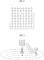
- FIG. 9 shows an example of a DPS CoMP operation according to an embodiment of the present invention.
- 3 TPs may include distributed antenna TPs sharing the same cell IR or separate cells having individual IDs.
- FIG. 9 shows an FD-MIMO (full dimension-MIMO) system capable of using a 2D beam as each TP is equipped with a vertical/horizontal antenna.
- 4 BF (beamformed) CSI-RS resources per TP are shown to a COMP UE.
- total 12 BF CSI-RSs are configured for the UE.
- Ports configuring the single CSI-RS resource are divided into a plurality of port groups, whereby the UE can be informed of 4 port groups. Namely, in FIG.
- the 4 CSI-RS resources transmitted by TP 1 are configured for the UE as a substantially single CSI-RS resource
- CSI-RS 0 indicates a port group configured with some ports of the single CSI-RS resource
- CSI-RS 1 indicates a port group configured with other some ports of the single CSI-RS resource, and so on.
- Table 3 shows a CSI process configured for a UE, a TP index corresponding to each CSI process, and a BF CSI-RS index.
- a UE Since a size of a currently defined PQI field is 2 bits, a UE can be informed of maximum 4 CSI-RSs (i.e., QCLed CSI-RSs) for which QCL assumption with DM-RS is possible. Since the number of TPs participating in CoMP is limited to 3 in aspect of a single UE in the existing CoMP, a 2-bit size field is enough to indicate QCL information. Yet, if CoMP and FD-MIMO are applied together like FIG. 9 , 3 or more CSI-RSs are configured for a UE. In FIG. 9 , it can be observed that total 12 BF CSI-RSs are configured to the UE. Hence, the current 2-bit size PQI field is not enough to indicate one of the 12 BF CSI-RSs.
- CSI-RSs i.e., QCLed CSI-RSs
- a UE can perform DM-RS channel estimation. For example, if the UE receives data from TP 1 and the data is transmitted using a beam applied to BF CSI-RS 0, although CSI-RS 1 is indicated through a PQI field, since CSI-RS 0 and CSI-RS 1 are the resources transmitted by the same TP, there is no problem in using QCL information.
- a base station defines a representative CSI-RS per CSI process configured for a UE for a UE one by one using a PQI field.
- CSI-RS 0 that is a representative CSI-RS of CSI process
- CSI-RS 4 that is a representative CSI-RS of CSI process 1
- CSI-RS 8 that is a representative CSI-RS of CSI process 2 are configured for PQI state 0, PQI state 1 and PQI state 2 through RRC signaling, respectively.
- a QCL CSI process index can be defined in a PQI state instead of a QCL CSI-RS index.
- QCL CSI-RS may be used for a random CSI-RS in a CSI process to obtain QCL information, or a previously agreed CSI-RS index, e.g., a lowest CSI-RS index in a CSI process may be used for QCL information acquisition.
- the UE checks the representative CSI-RS through the PQI field, checks a CSI process having the representative CSI-RS belong thereto, and checks a CRI fed back in the CSI process most recently.
- the UE performs DM-RS channel estimation by obtaining QCL information through CSI-RS connected to the corresponding CRI. For example, if CSI-RS 0 is indicated by the PQI field, the UE checks a most recently fed-back CRI of the CSI process 0 before receiving a PQI.
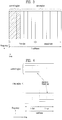
- FIG. 10 shows an aperiodic CSI feedback through PUSCH and an example of performing a PDSCH transmission based on it according to an embodiment of the present invention.
- DL data (PDSCH) and DCI are transmitted in SF (subframe) 2 and that PQI in the DCI indicates CSI-RS 0.
- a UE determines QCL CSI-RS with reference to CRI reported in SF 0. If the CRI reported in SF 0 indicates CSI-RS 3, the UE performs channel estimation using QCL information of CSI-RS 3.
- the UE determines QCL CSI-RS with reference to CRI of SF 1.
- the following problem is caused.
- a base station is unable to perform data scheduling of SF 2, which is the right next subframe, using the CRI received in SF 1. This is because, in order to perform scheduling using the CRI received in SF 1, a time amounting to N subframe(s) at least is required by considering a time taken to perform the calculation for the scheduling.
- the UE preferably checks a most recently fed-back CRI with reference to a timing point ahead of N subframe(s) before receiving PQI.
- N may be notified to the UE by the base station through higher layer signaling such as RRC signaling, fixed to a specific value in advance, or reported to the base station by the UE.
- the base station fails in CRI/CSI reception in SF 0, the above operation may cause a problem. To solve this problem, the following operation can be considered.
- FIG. 11 shows an example of performing a periodic CSI feedback through PDSCH and a PDSCH transmission based on it according to an embodiment of the present invention.
- N 2 if DL data is transmitted in an SF3 timing, a UE searches for QCL information with reference to CRI of SF 0. Yet, since a base station receives CQI and PMI corresponding to the CRI in an SF2 timing, it causes a problem that data scheduling cannot be performed using the CRI and CSI.
- N i.e., N of FIG. 11
- N can be determined as a function of a CQI period, a subframe offset of CRI over CQI , and an N value (i.e., N of FIG. 10 ) of PUSCH CSI feedback.
- a base station can signal whether to use PQI by the proposed or existing scheme or override PQI for other usages, through higher layer signalling such as RRC signalling. For example, if the base station configures QCL type A or a single CSI process, PQI is used by being overridden for other usages.
- the UE can assume that a random CSI-RS configured in the CSI process and a DM-RS are QCLed.
- the base station informs the UE of the single CSI process through DCI and the like and the UE can assume the QCL between the random CSI-RS configured in the CSI process and the DM-RS.
- the UE receives a QCL CSI-RS index through DCI conventionally and is able to assume the QCL between the random CSI-RS configured in the CSI-RS existing CSI process and the DM-RS.
- a QCL type is defined as a QCL type C.
- QCL type C Since several QCLed CSI-RSs exist in a CSI process according to QCL type C, reference signal density for a UE to calculate QCL information is higher than that of the existing QCL type B. For example, in QCL type B, there exists a single QCL CSI-RS by a minimum period of 5 ms. Yet, in QCL type C, as 5 CSI-RSs are configured in a single CSI process, there exist 5 QCL CSI-RSs. These 5 CSI-RSs have the period of 5 ms and different subframe offsets.
- a UE having QCL type C configured thereto can accurately estimate Doppler spread and Doppler shift using QCL CSI-RS existing in every subframe. Eventually, the UE does not need to obtain QCL information from CRS but is able to perform DM-RS estimation by acquiring accurate QCL information with CSI-RS only.
- FIG. 12 is a diagram for a base station and a user equipment capable of being applied to an embodiment of the present invention.
- a wireless communication system includes a base station (BS) 1210 and a user equipment (UE) 1220.
- the BS 1210 includes a processor 1213, a memory 1214 and a radio frequency (RF) units 1211/1212.
- the processor 1213 can be configured to implement the proposed functions, processes and/or methods.
- the memory 1214 is connected with the processor 1213 and then stores various kinds of information associated with an operation of the processor 1213.
- the RF units 1211/1212 are connected with the processor 1213 and transmits and/or receives a radio signal.
- the user equipment 1220 includes a processor 1223, a memory 1224 and a radio frequency (RF) unit 1221/1222.
- the processor 1223 can be configured to implement the proposed functions, processes and/or methods.
- the memory 1224 is connected with the processor 1223 and then stores various kinds of information associated with an operation of the processor 1223.
- the RF unit 1221/1222 is connected with the processor 1223 and transmits and/or receives a radio signal.
- the base station 1210 and/or the user equipment 1220 may have a single antenna or multiple antennas.
- eNode B may be performed by an upper node of the eNode B in some cases.
- various operations performed for communication with a user equipment can be performed by an eNode B or other networks except the eNode B.
- eNode B (eNB)' may be substituted with such a terminology as a fixed station, a Node B, a base station (BS), an access point (AP) and the like.
- Embodiments of the present invention can be implemented using various means. For instance, embodiments of the present invention can be implemented using hardware, firmware, software and/or any combinations thereof. In the implementation by hardware, a method according to each embodiment of the present invention can be implemented by at least one selected from the group consisting of ASICs (application specific integrated circuits), DSPs (digital signal processors), DSPDs (digital signal processing devices), PLDs (programmable logic devices), FPGAs (field programmable gate arrays), processor, controller, microcontroller, microprocessor and the like.
- ASICs application specific integrated circuits
- DSPs digital signal processors
- DSPDs digital signal processing devices
- PLDs programmable logic devices
- FPGAs field programmable gate arrays
- processor controller, microcontroller, microprocessor and the like.
- a method according to each embodiment of the present invention can be implemented by modules, procedures, and/or functions for performing the above-explained functions or operations.
- Software code is stored in a memory unit and is then drivable by a processor.
- the memory unit is provided within or outside the processor to exchange data with the processor through the various means known in public.
- the present invention can be used for a wireless communication device such as a terminal, a relay, a base station and the like.
Landscapes
- Engineering & Computer Science (AREA)
- Signal Processing (AREA)
- Computer Networks & Wireless Communication (AREA)
- Physics & Mathematics (AREA)
- Mathematical Physics (AREA)
- Mobile Radio Communication Systems (AREA)
Applications Claiming Priority (2)
| Application Number | Priority Date | Filing Date | Title |
|---|---|---|---|
| US201662276233P | 2016-01-08 | 2016-01-08 | |
| PCT/KR2017/000149 WO2017119741A1 (ko) | 2016-01-08 | 2017-01-05 | 무선통신 시스템에서 단말이 기지국으로 부터 하향링크 신호를 수신하는 방법 및 이를 위한 장치 |
Publications (3)
| Publication Number | Publication Date |
|---|---|
| EP3402105A1 EP3402105A1 (en) | 2018-11-14 |
| EP3402105A4 EP3402105A4 (en) | 2019-07-31 |
| EP3402105B1 true EP3402105B1 (en) | 2021-10-06 |
Family
ID=59273791
Family Applications (1)
| Application Number | Title | Priority Date | Filing Date |
|---|---|---|---|
| EP17736113.6A Active EP3402105B1 (en) | 2016-01-08 | 2017-01-05 | Method by which terminal receives downlink signal from base station in wireless communication system, and device therefor |
Country Status (3)
| Country | Link |
|---|---|
| US (1) | US10707937B2 (ko) |
| EP (1) | EP3402105B1 (ko) |
| WO (1) | WO2017119741A1 (ko) |
Families Citing this family (15)
| Publication number | Priority date | Publication date | Assignee | Title |
|---|---|---|---|---|
| US10505597B2 (en) * | 2016-05-09 | 2019-12-10 | Qualcomm Incorporated | Reference signals and link adaptation for massive MIMO |
| CN109474993B (zh) * | 2017-09-08 | 2022-10-28 | 北京紫光展锐通信技术有限公司 | 下行波束指示方法、装置及基站 |
| US10841955B2 (en) * | 2017-09-12 | 2020-11-17 | Mediatek Inc. | Rach quasi-colocation association |
| WO2019069132A1 (en) | 2017-10-02 | 2019-04-11 | Lenovo (Singapore) Pte, Ltd. | UPLINK POWER CONTROL |
| EP3637629B1 (en) * | 2018-01-19 | 2021-04-14 | Guangdong Oppo Mobile Telecommunications Corp., Ltd. | Channel state information (csi) measurement method, terminal device and network device |
| WO2020008574A1 (ja) * | 2018-07-04 | 2020-01-09 | 株式会社Nttドコモ | ユーザ端末 |
| KR102101829B1 (ko) * | 2018-08-09 | 2020-04-17 | 엘지전자 주식회사 | 무선 통신 시스템에서 채널 상태 정보를 송수신하는 방법 및 이를 위한 장치 |
| WO2020029232A1 (en) * | 2018-08-10 | 2020-02-13 | Qualcomm Incorporated | Quasi-colocation indication for demodulation reference signals |
| WO2020056698A1 (en) * | 2018-09-20 | 2020-03-26 | Nokia Shanghai Bell Co., Ltd. | Methods and apparatuses for random access procedure in a telecommunication system |
| CN113728560B (zh) * | 2019-02-21 | 2024-06-25 | 株式会社Ntt都科摩 | 用户终端以及无线通信方法 |
| US11950264B2 (en) * | 2019-08-02 | 2024-04-02 | Qualcomm Incorporated | Joint sounding and measurement for access link and sidelink |
| JP7372620B2 (ja) * | 2019-10-11 | 2023-11-01 | 株式会社Nttドコモ | 端末、無線通信方法、基地局及びシステム |
| US20220361089A1 (en) * | 2021-05-06 | 2022-11-10 | Apple Inc. | Systems and methods for supporting evolving band regulations |
| WO2023004754A1 (en) * | 2021-07-30 | 2023-02-02 | Zte Corporation | Systems and methods for reference signaling design and configuration |
| US12520166B2 (en) * | 2023-01-05 | 2026-01-06 | Qualcomm Incorporated | Hybrid beamforming selection for higher-order MIMO |
Family Cites Families (8)
| Publication number | Priority date | Publication date | Assignee | Title |
|---|---|---|---|---|
| AU2013250063B2 (en) | 2012-04-19 | 2017-11-02 | Samsung Electronics Co., Ltd. | Method and apparatus for quasi co-location identification of reference symbol ports for coordinated multi-point communication systems |
| KR102086515B1 (ko) | 2012-09-16 | 2020-03-09 | 엘지전자 주식회사 | 무선 통신 시스템에서 안테나 포트 관계를 고려한 하향링크 신호 송수신 방법 및 장치 |
| CN104685802B (zh) | 2012-10-04 | 2018-03-23 | Lg电子株式会社 | 在无线通信系统中通过考虑天线端口关系收发下行链路信号的方法和设备 |
| US9307521B2 (en) | 2012-11-01 | 2016-04-05 | Samsung Electronics Co., Ltd. | Transmission scheme and quasi co-location assumption of antenna ports for PDSCH of transmission mode 10 for LTE advanced |
| JP6514203B2 (ja) | 2013-07-29 | 2019-05-15 | エルジー エレクトロニクス インコーポレイティド | 無線通信システムにおいてNIB CoMP方法及び装置 |
| US20150049626A1 (en) | 2013-08-14 | 2015-02-19 | Qualcomm Incorporated | Enabling coordinated multipoint (comp) operation |
| US20160105817A1 (en) * | 2014-10-10 | 2016-04-14 | Telefonaktiebolaget L M Ericsson (Publ) | Method for csi feedback |
| US10225054B2 (en) * | 2014-11-07 | 2019-03-05 | Electronics And Telecommunications Research Institute | Method and apparatus for transmitting reference signal, method and apparatus for measuring and reporting channel state information, and method for configuring the same |
-
2017
- 2017-01-05 EP EP17736113.6A patent/EP3402105B1/en active Active
- 2017-01-05 WO PCT/KR2017/000149 patent/WO2017119741A1/ko not_active Ceased
- 2017-01-05 US US16/067,473 patent/US10707937B2/en active Active
Non-Patent Citations (1)
| Title |
|---|
| None * |
Also Published As
| Publication number | Publication date |
|---|---|
| US10707937B2 (en) | 2020-07-07 |
| WO2017119741A1 (ko) | 2017-07-13 |
| EP3402105A4 (en) | 2019-07-31 |
| US20190013854A1 (en) | 2019-01-10 |
| EP3402105A1 (en) | 2018-11-14 |
Similar Documents
| Publication | Publication Date | Title |
|---|---|---|
| EP3402105B1 (en) | Method by which terminal receives downlink signal from base station in wireless communication system, and device therefor | |
| US10651914B2 (en) | Method for reporting CSI in wireless communication system and apparatus therefor | |
| US10425142B2 (en) | Method for transmitting and receiving channel state information in wireless communication system, and apparatus therefor | |
| EP2993804B1 (en) | Method for transmitting feedback information through terminal to for split beamforming in wireless communication system and apparatus therefor | |
| CN105308879B (zh) | 用于在无线通信系统中执行基于部分天线阵列的波束形成的方法及其装置 | |
| US11153050B2 (en) | Method for determining bit size of rank indicator in wireless communication system, and device therefor | |
| US10944183B2 (en) | Method for transmitting and receiving channel state information in multi-antenna wireless communication system, and device therefor | |
| US10419095B2 (en) | Method for configuring channel state information using polarization characteristics of antenna in wireless communication system and device therefor | |
| US10263671B2 (en) | Method for reporting reference signal indicator to base station by terminal in wireless communication system and apparatus therefor | |
| US10171154B2 (en) | Method for reporting beam index for 3D MIMO transmission in wireless communication system, and device therefor | |
| EP3174218A1 (en) | Method and apparatus for transmitting channel state information in wireless access system | |
| KR102334620B1 (ko) | 채널 추정을 수행하기 위한 방법 및 이를 위한 장치 | |
| WO2015115705A1 (en) | Feedback reporting method for massive antenna array based beamforming in wireless communication system, and apparatus therefor | |
| WO2015016489A1 (en) | Method for reporting channel state information for partial antenna array based beamforming in wireless communication system, and apparatus therefor | |
| US20180034523A1 (en) | Method for feeding back csi information in wireless communication system, and apparatus therefor | |
| EP3203649A1 (en) | Method for configuring reference signal for three-dimensional mimo in wireless communication system and apparatus therefor | |
| US10608724B2 (en) | Method for reporting CSI in wireless communication system and device for same | |
| US10476570B2 (en) | Method by which terminal reports channel status information to base station in wireless communication system, and apparatus therefor |
Legal Events
| Date | Code | Title | Description |
|---|---|---|---|
| STAA | Information on the status of an ep patent application or granted ep patent |
Free format text: STATUS: THE INTERNATIONAL PUBLICATION HAS BEEN MADE |
|
| PUAI | Public reference made under article 153(3) epc to a published international application that has entered the european phase |
Free format text: ORIGINAL CODE: 0009012 |
|
| STAA | Information on the status of an ep patent application or granted ep patent |
Free format text: STATUS: REQUEST FOR EXAMINATION WAS MADE |
|
| 17P | Request for examination filed |
Effective date: 20180716 |
|
| AK | Designated contracting states |
Kind code of ref document: A1 Designated state(s): AL AT BE BG CH CY CZ DE DK EE ES FI FR GB GR HR HU IE IS IT LI LT LU LV MC MK MT NL NO PL PT RO RS SE SI SK SM TR |
|
| AX | Request for extension of the european patent |
Extension state: BA ME |
|
| DAV | Request for validation of the european patent (deleted) | ||
| DAX | Request for extension of the european patent (deleted) | ||
| A4 | Supplementary search report drawn up and despatched |
Effective date: 20190701 |
|
| RIC1 | Information provided on ipc code assigned before grant |
Ipc: H04L 1/06 20060101AFI20190625BHEP Ipc: H04L 5/00 20060101ALI20190625BHEP Ipc: H04B 7/02 20180101ALI20190625BHEP Ipc: H04B 7/06 20060101ALI20190625BHEP |
|
| STAA | Information on the status of an ep patent application or granted ep patent |
Free format text: STATUS: EXAMINATION IS IN PROGRESS |
|
| 17Q | First examination report despatched |
Effective date: 20201113 |
|
| GRAP | Despatch of communication of intention to grant a patent |
Free format text: ORIGINAL CODE: EPIDOSNIGR1 |
|
| STAA | Information on the status of an ep patent application or granted ep patent |
Free format text: STATUS: GRANT OF PATENT IS INTENDED |
|
| INTG | Intention to grant announced |
Effective date: 20210604 |
|
| GRAS | Grant fee paid |
Free format text: ORIGINAL CODE: EPIDOSNIGR3 |
|
| GRAA | (expected) grant |
Free format text: ORIGINAL CODE: 0009210 |
|
| STAA | Information on the status of an ep patent application or granted ep patent |
Free format text: STATUS: THE PATENT HAS BEEN GRANTED |
|
| AK | Designated contracting states |
Kind code of ref document: B1 Designated state(s): AL AT BE BG CH CY CZ DE DK EE ES FI FR GB GR HR HU IE IS IT LI LT LU LV MC MK MT NL NO PL PT RO RS SE SI SK SM TR |
|
| REG | Reference to a national code |
Ref country code: GB Ref legal event code: FG4D |
|
| REG | Reference to a national code |
Ref country code: CH Ref legal event code: EP Ref country code: AT Ref legal event code: REF Ref document number: 1437124 Country of ref document: AT Kind code of ref document: T Effective date: 20211015 |
|
| REG | Reference to a national code |
Ref country code: DE Ref legal event code: R096 Ref document number: 602017047136 Country of ref document: DE |
|
| REG | Reference to a national code |
Ref country code: IE Ref legal event code: FG4D |
|
| REG | Reference to a national code |
Ref country code: LT Ref legal event code: MG9D |
|
| REG | Reference to a national code |
Ref country code: NL Ref legal event code: MP Effective date: 20211006 |
|
| REG | Reference to a national code |
Ref country code: AT Ref legal event code: MK05 Ref document number: 1437124 Country of ref document: AT Kind code of ref document: T Effective date: 20211006 |
|
| PG25 | Lapsed in a contracting state [announced via postgrant information from national office to epo] |
Ref country code: RS Free format text: LAPSE BECAUSE OF FAILURE TO SUBMIT A TRANSLATION OF THE DESCRIPTION OR TO PAY THE FEE WITHIN THE PRESCRIBED TIME-LIMIT Effective date: 20211006 Ref country code: LT Free format text: LAPSE BECAUSE OF FAILURE TO SUBMIT A TRANSLATION OF THE DESCRIPTION OR TO PAY THE FEE WITHIN THE PRESCRIBED TIME-LIMIT Effective date: 20211006 Ref country code: FI Free format text: LAPSE BECAUSE OF FAILURE TO SUBMIT A TRANSLATION OF THE DESCRIPTION OR TO PAY THE FEE WITHIN THE PRESCRIBED TIME-LIMIT Effective date: 20211006 Ref country code: BG Free format text: LAPSE BECAUSE OF FAILURE TO SUBMIT A TRANSLATION OF THE DESCRIPTION OR TO PAY THE FEE WITHIN THE PRESCRIBED TIME-LIMIT Effective date: 20220106 Ref country code: AT Free format text: LAPSE BECAUSE OF FAILURE TO SUBMIT A TRANSLATION OF THE DESCRIPTION OR TO PAY THE FEE WITHIN THE PRESCRIBED TIME-LIMIT Effective date: 20211006 |
|
| PG25 | Lapsed in a contracting state [announced via postgrant information from national office to epo] |
Ref country code: IS Free format text: LAPSE BECAUSE OF FAILURE TO SUBMIT A TRANSLATION OF THE DESCRIPTION OR TO PAY THE FEE WITHIN THE PRESCRIBED TIME-LIMIT Effective date: 20220206 Ref country code: SE Free format text: LAPSE BECAUSE OF FAILURE TO SUBMIT A TRANSLATION OF THE DESCRIPTION OR TO PAY THE FEE WITHIN THE PRESCRIBED TIME-LIMIT Effective date: 20211006 Ref country code: PT Free format text: LAPSE BECAUSE OF FAILURE TO SUBMIT A TRANSLATION OF THE DESCRIPTION OR TO PAY THE FEE WITHIN THE PRESCRIBED TIME-LIMIT Effective date: 20220207 Ref country code: PL Free format text: LAPSE BECAUSE OF FAILURE TO SUBMIT A TRANSLATION OF THE DESCRIPTION OR TO PAY THE FEE WITHIN THE PRESCRIBED TIME-LIMIT Effective date: 20211006 Ref country code: NO Free format text: LAPSE BECAUSE OF FAILURE TO SUBMIT A TRANSLATION OF THE DESCRIPTION OR TO PAY THE FEE WITHIN THE PRESCRIBED TIME-LIMIT Effective date: 20220106 Ref country code: NL Free format text: LAPSE BECAUSE OF FAILURE TO SUBMIT A TRANSLATION OF THE DESCRIPTION OR TO PAY THE FEE WITHIN THE PRESCRIBED TIME-LIMIT Effective date: 20211006 Ref country code: LV Free format text: LAPSE BECAUSE OF FAILURE TO SUBMIT A TRANSLATION OF THE DESCRIPTION OR TO PAY THE FEE WITHIN THE PRESCRIBED TIME-LIMIT Effective date: 20211006 Ref country code: HR Free format text: LAPSE BECAUSE OF FAILURE TO SUBMIT A TRANSLATION OF THE DESCRIPTION OR TO PAY THE FEE WITHIN THE PRESCRIBED TIME-LIMIT Effective date: 20211006 Ref country code: GR Free format text: LAPSE BECAUSE OF FAILURE TO SUBMIT A TRANSLATION OF THE DESCRIPTION OR TO PAY THE FEE WITHIN THE PRESCRIBED TIME-LIMIT Effective date: 20220107 Ref country code: ES Free format text: LAPSE BECAUSE OF FAILURE TO SUBMIT A TRANSLATION OF THE DESCRIPTION OR TO PAY THE FEE WITHIN THE PRESCRIBED TIME-LIMIT Effective date: 20211006 |
|
| REG | Reference to a national code |
Ref country code: DE Ref legal event code: R097 Ref document number: 602017047136 Country of ref document: DE |
|
| PG25 | Lapsed in a contracting state [announced via postgrant information from national office to epo] |
Ref country code: SM Free format text: LAPSE BECAUSE OF FAILURE TO SUBMIT A TRANSLATION OF THE DESCRIPTION OR TO PAY THE FEE WITHIN THE PRESCRIBED TIME-LIMIT Effective date: 20211006 Ref country code: SK Free format text: LAPSE BECAUSE OF FAILURE TO SUBMIT A TRANSLATION OF THE DESCRIPTION OR TO PAY THE FEE WITHIN THE PRESCRIBED TIME-LIMIT Effective date: 20211006 Ref country code: RO Free format text: LAPSE BECAUSE OF FAILURE TO SUBMIT A TRANSLATION OF THE DESCRIPTION OR TO PAY THE FEE WITHIN THE PRESCRIBED TIME-LIMIT Effective date: 20211006 Ref country code: EE Free format text: LAPSE BECAUSE OF FAILURE TO SUBMIT A TRANSLATION OF THE DESCRIPTION OR TO PAY THE FEE WITHIN THE PRESCRIBED TIME-LIMIT Effective date: 20211006 Ref country code: DK Free format text: LAPSE BECAUSE OF FAILURE TO SUBMIT A TRANSLATION OF THE DESCRIPTION OR TO PAY THE FEE WITHIN THE PRESCRIBED TIME-LIMIT Effective date: 20211006 Ref country code: CZ Free format text: LAPSE BECAUSE OF FAILURE TO SUBMIT A TRANSLATION OF THE DESCRIPTION OR TO PAY THE FEE WITHIN THE PRESCRIBED TIME-LIMIT Effective date: 20211006 |
|
| PLBE | No opposition filed within time limit |
Free format text: ORIGINAL CODE: 0009261 |
|
| STAA | Information on the status of an ep patent application or granted ep patent |
Free format text: STATUS: NO OPPOSITION FILED WITHIN TIME LIMIT |
|
| PG25 | Lapsed in a contracting state [announced via postgrant information from national office to epo] |
Ref country code: MC Free format text: LAPSE BECAUSE OF FAILURE TO SUBMIT A TRANSLATION OF THE DESCRIPTION OR TO PAY THE FEE WITHIN THE PRESCRIBED TIME-LIMIT Effective date: 20211006 |
|
| REG | Reference to a national code |
Ref country code: CH Ref legal event code: PL |
|
| 26N | No opposition filed |
Effective date: 20220707 |
|
| GBPC | Gb: european patent ceased through non-payment of renewal fee |
Effective date: 20220106 |
|
| REG | Reference to a national code |
Ref country code: BE Ref legal event code: MM Effective date: 20220131 |
|
| PG25 | Lapsed in a contracting state [announced via postgrant information from national office to epo] |
Ref country code: LU Free format text: LAPSE BECAUSE OF NON-PAYMENT OF DUE FEES Effective date: 20220105 Ref country code: GB Free format text: LAPSE BECAUSE OF NON-PAYMENT OF DUE FEES Effective date: 20220106 Ref country code: AL Free format text: LAPSE BECAUSE OF FAILURE TO SUBMIT A TRANSLATION OF THE DESCRIPTION OR TO PAY THE FEE WITHIN THE PRESCRIBED TIME-LIMIT Effective date: 20211006 |
|
| PG25 | Lapsed in a contracting state [announced via postgrant information from national office to epo] |
Ref country code: SI Free format text: LAPSE BECAUSE OF FAILURE TO SUBMIT A TRANSLATION OF THE DESCRIPTION OR TO PAY THE FEE WITHIN THE PRESCRIBED TIME-LIMIT Effective date: 20211006 Ref country code: FR Free format text: LAPSE BECAUSE OF NON-PAYMENT OF DUE FEES Effective date: 20220131 Ref country code: BE Free format text: LAPSE BECAUSE OF NON-PAYMENT OF DUE FEES Effective date: 20220131 |
|
| PG25 | Lapsed in a contracting state [announced via postgrant information from national office to epo] |
Ref country code: LI Free format text: LAPSE BECAUSE OF NON-PAYMENT OF DUE FEES Effective date: 20220131 Ref country code: CH Free format text: LAPSE BECAUSE OF NON-PAYMENT OF DUE FEES Effective date: 20220131 |
|
| PG25 | Lapsed in a contracting state [announced via postgrant information from national office to epo] |
Ref country code: IE Free format text: LAPSE BECAUSE OF NON-PAYMENT OF DUE FEES Effective date: 20220105 |
|
| PG25 | Lapsed in a contracting state [announced via postgrant information from national office to epo] |
Ref country code: IT Free format text: LAPSE BECAUSE OF FAILURE TO SUBMIT A TRANSLATION OF THE DESCRIPTION OR TO PAY THE FEE WITHIN THE PRESCRIBED TIME-LIMIT Effective date: 20211006 |
|
| PG25 | Lapsed in a contracting state [announced via postgrant information from national office to epo] |
Ref country code: HU Free format text: LAPSE BECAUSE OF FAILURE TO SUBMIT A TRANSLATION OF THE DESCRIPTION OR TO PAY THE FEE WITHIN THE PRESCRIBED TIME-LIMIT; INVALID AB INITIO Effective date: 20170105 |
|
| PG25 | Lapsed in a contracting state [announced via postgrant information from national office to epo] |
Ref country code: MK Free format text: LAPSE BECAUSE OF FAILURE TO SUBMIT A TRANSLATION OF THE DESCRIPTION OR TO PAY THE FEE WITHIN THE PRESCRIBED TIME-LIMIT Effective date: 20211006 Ref country code: CY Free format text: LAPSE BECAUSE OF FAILURE TO SUBMIT A TRANSLATION OF THE DESCRIPTION OR TO PAY THE FEE WITHIN THE PRESCRIBED TIME-LIMIT Effective date: 20211006 |
|
| PG25 | Lapsed in a contracting state [announced via postgrant information from national office to epo] |
Ref country code: TR Free format text: LAPSE BECAUSE OF FAILURE TO SUBMIT A TRANSLATION OF THE DESCRIPTION OR TO PAY THE FEE WITHIN THE PRESCRIBED TIME-LIMIT Effective date: 20211006 |
|
| PG25 | Lapsed in a contracting state [announced via postgrant information from national office to epo] |
Ref country code: MT Free format text: LAPSE BECAUSE OF FAILURE TO SUBMIT A TRANSLATION OF THE DESCRIPTION OR TO PAY THE FEE WITHIN THE PRESCRIBED TIME-LIMIT Effective date: 20211006 |
|
| PGFP | Annual fee paid to national office [announced via postgrant information from national office to epo] |
Ref country code: DE Payment date: 20251208 Year of fee payment: 10 |