EP3402111B1 - Dispositives et procédés d'indication de canal dans un réseau local sans fil - Google Patents
Dispositives et procédés d'indication de canal dans un réseau local sans fil Download PDFInfo
- Publication number
- EP3402111B1 EP3402111B1 EP16889144.8A EP16889144A EP3402111B1 EP 3402111 B1 EP3402111 B1 EP 3402111B1 EP 16889144 A EP16889144 A EP 16889144A EP 3402111 B1 EP3402111 B1 EP 3402111B1
- Authority
- EP
- European Patent Office
- Prior art keywords
- channel
- mhz channel
- mhz
- primary
- data transmission
- Prior art date
- Legal status (The legal status is an assumption and is not a legal conclusion. Google has not performed a legal analysis and makes no representation as to the accuracy of the status listed.)
- Active
Links
Images







Classifications
-
- H—ELECTRICITY
- H04—ELECTRIC COMMUNICATION TECHNIQUE
- H04L—TRANSMISSION OF DIGITAL INFORMATION, e.g. TELEGRAPHIC COMMUNICATION
- H04L5/00—Arrangements affording multiple use of the transmission path
- H04L5/003—Arrangements for allocating sub-channels of the transmission path
- H04L5/0048—Allocation of pilot signals, i.e. of signals known to the receiver
-
- H—ELECTRICITY
- H04—ELECTRIC COMMUNICATION TECHNIQUE
- H04L—TRANSMISSION OF DIGITAL INFORMATION, e.g. TELEGRAPHIC COMMUNICATION
- H04L5/00—Arrangements affording multiple use of the transmission path
- H04L5/003—Arrangements for allocating sub-channels of the transmission path
- H04L5/0044—Allocation of payload; Allocation of data channels, e.g. PDSCH or PUSCH
-
- H—ELECTRICITY
- H04—ELECTRIC COMMUNICATION TECHNIQUE
- H04L—TRANSMISSION OF DIGITAL INFORMATION, e.g. TELEGRAPHIC COMMUNICATION
- H04L5/00—Arrangements affording multiple use of the transmission path
- H04L5/0091—Signalling for the administration of the divided path, e.g. signalling of configuration information
- H04L5/0092—Indication of how the channel is divided
-
- H—ELECTRICITY
- H04—ELECTRIC COMMUNICATION TECHNIQUE
- H04L—TRANSMISSION OF DIGITAL INFORMATION, e.g. TELEGRAPHIC COMMUNICATION
- H04L27/00—Modulated-carrier systems
- H04L27/26—Systems using multi-frequency codes
- H04L27/2601—Multicarrier modulation systems
- H04L27/2602—Signal structure
-
- H—ELECTRICITY
- H04—ELECTRIC COMMUNICATION TECHNIQUE
- H04L—TRANSMISSION OF DIGITAL INFORMATION, e.g. TELEGRAPHIC COMMUNICATION
- H04L5/00—Arrangements affording multiple use of the transmission path
- H04L5/003—Arrangements for allocating sub-channels of the transmission path
- H04L5/0053—Allocation of signalling, i.e. of overhead other than pilot signals
-
- H—ELECTRICITY
- H04—ELECTRIC COMMUNICATION TECHNIQUE
- H04L—TRANSMISSION OF DIGITAL INFORMATION, e.g. TELEGRAPHIC COMMUNICATION
- H04L5/00—Arrangements affording multiple use of the transmission path
- H04L5/0091—Signalling for the administration of the divided path, e.g. signalling of configuration information
- H04L5/0094—Indication of how sub-channels of the path are allocated
-
- H—ELECTRICITY
- H04—ELECTRIC COMMUNICATION TECHNIQUE
- H04W—WIRELESS COMMUNICATION NETWORKS
- H04W24/00—Supervisory, monitoring or testing arrangements
- H04W24/02—Arrangements for optimising operational condition
-
- H—ELECTRICITY
- H04—ELECTRIC COMMUNICATION TECHNIQUE
- H04W—WIRELESS COMMUNICATION NETWORKS
- H04W72/00—Local resource management
- H04W72/04—Wireless resource allocation
- H04W72/044—Wireless resource allocation based on the type of the allocated resource
- H04W72/0446—Resources in time domain, e.g. slots or frames
-
- H—ELECTRICITY
- H04—ELECTRIC COMMUNICATION TECHNIQUE
- H04B—TRANSMISSION
- H04B7/00—Radio transmission systems, i.e. using radiation field
- H04B7/02—Diversity systems; Multi-antenna system, i.e. transmission or reception using multiple antennas
- H04B7/04—Diversity systems; Multi-antenna system, i.e. transmission or reception using multiple antennas using two or more spaced independent antennas
- H04B7/0413—MIMO systems
- H04B7/0452—Multi-user MIMO systems
-
- H—ELECTRICITY
- H04—ELECTRIC COMMUNICATION TECHNIQUE
- H04L—TRANSMISSION OF DIGITAL INFORMATION, e.g. TELEGRAPHIC COMMUNICATION
- H04L27/00—Modulated-carrier systems
- H04L27/26—Systems using multi-frequency codes
- H04L27/2601—Multicarrier modulation systems
- H04L27/2602—Signal structure
- H04L27/2603—Signal structure ensuring backward compatibility with legacy system
-
- H—ELECTRICITY
- H04—ELECTRIC COMMUNICATION TECHNIQUE
- H04L—TRANSMISSION OF DIGITAL INFORMATION, e.g. TELEGRAPHIC COMMUNICATION
- H04L5/00—Arrangements affording multiple use of the transmission path
- H04L5/003—Arrangements for allocating sub-channels of the transmission path
- H04L5/0037—Inter-user or inter-terminal allocation
-
- H—ELECTRICITY
- H04—ELECTRIC COMMUNICATION TECHNIQUE
- H04L—TRANSMISSION OF DIGITAL INFORMATION, e.g. TELEGRAPHIC COMMUNICATION
- H04L5/00—Arrangements affording multiple use of the transmission path
- H04L5/003—Arrangements for allocating sub-channels of the transmission path
- H04L5/0058—Allocation criteria
- H04L5/0064—Rate requirement of the data, e.g. scalable bandwidth, data priority
-
- H—ELECTRICITY
- H04—ELECTRIC COMMUNICATION TECHNIQUE
- H04W—WIRELESS COMMUNICATION NETWORKS
- H04W48/00—Access restriction; Network selection; Access point selection
- H04W48/08—Access restriction or access information delivery, e.g. discovery data delivery
- H04W48/12—Access restriction or access information delivery, e.g. discovery data delivery using downlink control channel
-
- H—ELECTRICITY
- H04—ELECTRIC COMMUNICATION TECHNIQUE
- H04W—WIRELESS COMMUNICATION NETWORKS
- H04W84/00—Network topologies
- H04W84/02—Hierarchically pre-organised networks, e.g. paging networks, cellular networks, WLAN [Wireless Local Area Network] or WLL [Wireless Local Loop]
- H04W84/10—Small scale networks; Flat hierarchical networks
- H04W84/12—WLAN [Wireless Local Area Networks]
-
- Y—GENERAL TAGGING OF NEW TECHNOLOGICAL DEVELOPMENTS; GENERAL TAGGING OF CROSS-SECTIONAL TECHNOLOGIES SPANNING OVER SEVERAL SECTIONS OF THE IPC; TECHNICAL SUBJECTS COVERED BY FORMER USPC CROSS-REFERENCE ART COLLECTIONS [XRACs] AND DIGESTS
- Y02—TECHNOLOGIES OR APPLICATIONS FOR MITIGATION OR ADAPTATION AGAINST CLIMATE CHANGE
- Y02D—CLIMATE CHANGE MITIGATION TECHNOLOGIES IN INFORMATION AND COMMUNICATION TECHNOLOGIES [ICT], I.E. INFORMATION AND COMMUNICATION TECHNOLOGIES AIMING AT THE REDUCTION OF THEIR OWN ENERGY USE
- Y02D30/00—Reducing energy consumption in communication networks
- Y02D30/70—Reducing energy consumption in communication networks in wireless communication networks
Definitions
- the present invention relates to the field of communications technologies, and in particular, to a method and an apparatus for indicating a channel in a wireless local area network.
- a WLAN system obtains a higher transmission rate by using higher bandwidth.
- 20 MHz is usually used as a basic bandwidth unit.
- a bandwidth of 20 MHz is used in the 802.11a.
- the bandwidth is increased to 40 MHz in the 802.11n, and is increased to 80 MHz and 160 MHz in the 802.11ac.
- one 20 MHz channel is a primary 20 MHz channel, and a remaining 20 MHz channel is a secondary channel.
- a primary 20 MHz channel needs to be included. That is, when the primary 20 MHz channel is occupied, even if another channel is idle, the channel cannot be used.
- a channel bandwidth defined in the current standards has four modes: 20 MHz, 40 MHz, 80 MHz, and 160 (80+80) MHz.
- next-generation WLAN standard 802.11ax an intensive deployment scenario is mainly studied, and a study emphasis is turned from a peak throughput increment to spectral efficiency improvement.
- stations supporting different WLAN standards intensively coexist
- FIG. 1 each channel in FIG. 1 has a bandwidth of 20 MHz
- an 802.11n station performs transmission by using a bandwidth of 20 MHz
- a spectrum is cut during narrowband transmission performed by the 802.1In station, causing channels available to an 802.11ax station to be discontinuous.
- this document proposes several wider bandwidth (BW) transmission methods: method A, method B and method C to support more flexible wider bandwidth operations.
- the method A constructs a PPDU considering about non-contiguous span of channels and fixed extension
- the method B constructs a PPDU with contiguous span of channels and flexible extension
- the method C constructs a PPDU with non-contiguous span of channels and flexible extension.
- the BW subfield for indicating a bandwidth of a PPDU constructed by method A may be 3 bits
- the BW subfield for indicating a bandwidth of a PPDU constructed by method B may be 5 bits
- the BW subfield for indicating a bandwidth of a PPDU constructed by method C may be 7 bits.
- WO2015/088116 A1 is related to the field of wireless local area network (WLAN) and discloses a bandwidth (BW) field in an HEW-SIG field, and the BW field includes 8 bits. 8 bits of the BW field corresponds to values of a user orthogonal frequency division multiplexing (OFDM) position in unit of 2 bits.
- OFDM orthogonal frequency division multiplexing
- the present invention provides the methods, apparatuses and computer-readable medium of the appended independent claims, which are used for indicating a channel in a wireless local area network, so as indicate a discontinuous channel in a frequency domain.
- Embodiments of the present invention may be applied to a Wireless Local Area Network (WLAN).
- the wireless local area network may include multiple basic service sets (BSS).
- a network node in a basic service set is a station (STA), and the station includes an access point (AP) station and a non-access point station (Non-AP STA).
- Each basic service set may include one AP and multiple non-AP STAs associated with the AP.
- the access point (AP) station is also referred to as a wireless access point, a hotspot, or the like.
- An AP is an access point at which a mobile user accesses a wired network, and is mainly deployed at home and inside a building and a campus. A typical coverage radius is tens of or hundreds of meters. Certainly, the AP may be deployed outdoors.
- the AP is equivalent to a bridge connecting a wired network and a wireless network, and is mainly configured to: connect various wireless network clients together, and then connect the wireless network to the Ethernet.
- standards mainly used by the AP are the Institute of Electrical and Electronics Engineers (IEEE), 802.11 series.
- the AP may be a terminal device or a network device having a Wireless Fidelity (Wi-Fi)_chip.
- the AP may be a device supporting the 802.11ax standard.
- the non-access point (Non-AP STA) station may be a wireless communications chip, a wireless sensor, or a wireless communications terminal, such as a mobile phone supporting a Wi-Fi communications function, a tablet computer supporting a Wi-Fi communications function, a set-top box supporting a Wi-Fi communications function, a smart television supporting a Wi-Fi communications function, a smart wearable device supporting a Wi-Fi communications function, or a computer supporting a Wi-Fi communications function.
- the station may support the 802.11ax standard.
- FIG. 2 is a schematic diagram of a system of a typical WLAN deployment scenario.
- the system includes one AP and three STAs.
- the AP separately communicates with a STA 1, a STA 2, and a STA 3.
- Each of the AP and the STAs 1 to 3 may be used as a first station or a second station.
- channel division in the WLAN is shown in FIG. 3a , channels are numbered, and each of numbers 0 to 7 represents one 20 MHz channel.
- the number 0 channel represents a primary 20 MHz channel.
- the number 1 channel represents a secondary 20 MHz channel.
- the number 0 channel and the number 1 channel form a primary 40 MHz channel.
- the number 2 channel and the number 3 channel form a secondary 40 MHz channel.
- the number 0 channel, the number 1 channel, the number 2 channel, and the number 3 channel form a primary 80 MHz channel.
- the number 4 channel, the number 5 channel, the number 6 channel, and the number 7 channel form a secondary 80 MHz channel.
- the number 4 channel is adjacent to the number 5 channel.
- the number 5 channel is adjacent to the number 6 channel.
- the number 6 channel is adjacent to the number 7 channel.
- one unique 20 MHz channel is a primary 20 MHz channel
- adjacent 20 MHz channel on the left or right of the primary 20 MHz channel is a secondary 20 MHz channel
- the left or the right 20 MHz channel may be randomly selected, but only one can be selected.
- being left may also be described as being below
- being right may also be described as being above.
- Being left or below indicates that a frequency is lower than a frequency of the primary 20 MHz channel
- being right or above indicates that a frequency is higher than the frequency of the primary 20 MHz channel).
- the primary 20 MHz channel and the secondary 20 MHz channel form a primary 40 MHz channel.
- Adjacent 40 MHz channel on the left or right of the primary 40 MHz channel is a secondary 40 MHz channel (the left or the right 40 MHz may be randomly selected, but only one can be selected), and the primary 40 MHz channel and the secondary 40 MHz channel form a primary 80 MHz channel.
- 80 MHz channel on the left or right of the primary 80 MHz channel is a secondary 80 MHz channel (the left or the right 80 MHz channel may be randomly selected, but only one can be selected).
- the primary 80 MHz channel is adjacent to the secondary 80 MHz channel, the primary 80 MHz channel and the secondary 80 MHz channel form a 160 MHz channel.
- the primary 80 MHz channel and the secondary 80 MHz channel form an (80+80) MHz channel.
- the channels 0 to 7 may be arranged in multiple manners shown in FIG. 3b .
- two 20 MHz channels of secondary 40 MHz and four 20 MHz channels of secondary 80 MHz may be numbered from left to right or from right to left. This is not limited in the present invention.
- the number 0 channel is used as a primary 20 MHz channel.
- a data frame in the embodiments of the present invention is a possible 802.11ax data frame
- a data frame in the WLAN is generally a Physical Protocol Data Unit (PPDU).
- the PPDU includes a preamble field and a data field
- the preamble field includes a legacy preamble field and a high efficiency preamble field.
- the legacy preamble (L-preamble) field keeps compatible with an existing WLAN standard device, and includes an Legacy Short Training Field (L-STF), an Legacy Long Training Field (L-LTF), an Legacy Signaling Field (L-SIG), and an Repeated Legacy Signaling Field (RL-SIG).
- the legacy preamble field is followed by a high efficiency signal field A (HE-SIG-A), a high efficiency signal field B (HE-SIG-B), and an other HE preamble.
- HE-SIG-A high efficiency signal field A
- HE-SIG-B high efficiency signal field B
- other HE preamble is one field or a combination of multiple fields, and is not particularly limited to a specific field.
- the other HE preamble field is followed by the data field (Data).
- Data data field
- a name of the standard, a name of a field, or the like may be replaced with any other name, and shall not be construed as a limitation to the protection scope of the present invention.
- descriptions of the data frame are also applicable to subsequent embodiments.
- the HE-SIG-B field is separately encoded on each 20 MHz channel.
- An encoding structure is shown in FIG. 5 , and includes a common block field and a user specific field.
- the common block field includes information related to resource allocation, such as frequency domain RU allocation information, an RU allocated to MU-MIMO, and a quantity of users included in the MU-MIMO.
- the user specific field includes multiple user block fields. Each user block field includes information that is needed to analyze data of two stations. If a quantity of user fields indicated by RU allocation signaling of the common block field is an odd number, the last user block field may include information about only one station.
- a common block field and a user specific field of a station are transmitted on 20 MHz having the same station data.
- a frequency mapping of a common block field and a user specific field is shown in FIG. 8 .
- Content of an HE-SIG-B on the first 20 MHz channel and the third 20 MHz channel that are arranged from top to bottom according to frequencies is the same.
- Information carried on these channels is an HE-SIG-B 1, and the HE-SIG-B 1 includes signaling information of all stations whose data occupies at least some subcarriers of A242 or C242.
- content of an HE-SIG-B on the second 20 MHz channel and the fourth 20 MHz channel that are arranged from top to bottom according to frequencies is the same.
- Information carried on these channels is an HE-SIG-B 2, and the HE-SIG-B 2 includes signaling information of all stations whose data occupies at least some subcarriers of B242 or D242.
- a frequency mapping of a common block field and a user specific field is shown in FIG. 9 .
- Content of an HE-SIG-B on the first 20 MHz channel, the third 20 MHz channel, the fifth 20 MHz channel, and the seventh 20 MHz channel that are arranged from top to bottom according to frequencies is the same.
- Information carried on these channels is an HE-SIG-B 1, and the HE-SIG-B 1 includes signaling information of all stations whose data occupies at least some subcarriers of A1-242, C1-242, A2-242, or C2-242.
- an HE-SIG-B on the second 20 MHz channel, the fourth 20 MHz channel, the sixth 20 MHz channel, and the eighth 20 MHz channel that are arranged from top to bottom according to frequencies is the same.
- Information carried on these channels is an HE-SIG-B 2, and the HE-SIG-B 2 includes signaling information of all stations whose data occupies at least some subcarriers of B 1-242, D1-242, B2-242, or D2-242.
- the descriptions of the PPDU are also applicable to all the embodiments.
- Embodiment 1 of the present invention provides a method, which is applied to a WLAN, for indicating a channel.
- the method may be applied to a station, for example, the AP and the STA 1 to the STA 3 in FIG. 2 .
- the station may support a next-generation WLAN standard, for example, the 802.11ax standard.
- FIG. 10 is an example block diagram of the method for indicating a channel. Specific steps are as follows:
- the channel bonding (CB) identifier includes at least one bit, and one bit is used as an example below for description. If the channel bonding identifier is a first value, the data transmission channel is continuous in the frequency domain; or if the channel bonding identifier is a second value, the data transmission channel includes multiple discontinuous channels in the frequency domain.
- first value and the second value of the channel bonding identifier are not limited in the present invention.
- the first value is “0” and the second value is “1”.
- the first value is "1" and the second value is “0".
- the foregoing two cases are both in the protection scope of the present invention.
- the case in which the first value is “0” and the second value is “1” is specifically used below for description.
- indicating the data transmission channel by using both the bandwidth identifier and the channel bonding identifier includes at least 10 implementations.
- Implementation 1 If the channel bonding identifier is the first value, and the bandwidth identifier is a first value, the data transmission channel includes a primary 20 MHz channel;
- the bandwidth (BW) identifier includes at least two bits, and two bits are used as an example below for description. Further, a value range of the first value, the second value, the third value, and the fourth value of the bandwidth identifier is [00, 01, 10, 11]. A specific mapping relationship of a value of the bandwidth identifier is not limited in the present invention. For convenience of description, descriptions are provided below with reference to a case in which the first value is "00", the second value is "01”, the third value is "10”, and the fourth value is "11".
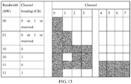
- the implementation 1 is specifically described with reference to FIG. 11 .
- a data transmission bandwidth is a primary 20 MHz channel, that is, the channel 0.
- a value of the channel bonding identifier may be 0, 1, or reserved.
- the data transmission bandwidth is a primary 20 MHz channel and a secondary 20 MHz channel, that is, the channels 0 and 1.
- the value of the channel bonding identifier may be 0, 1, or reserved.
- the data transmission bandwidth is a primary 20 MHz channel, a secondary 20 MHz channel, and a secondary 40 MHz channel, that is, the channels 0 to 3.
- the data transmission bandwidth is a primary 20 MHz channel and a secondary 40 MHz channel, that is, the channels 0, 2, and 3.
- the data transmission bandwidth is a primary 20 MHz channel, a secondary 20 MHz channel, a secondary 40 MHz channel, and a secondary 80 MHz channel, that is, the channels 0 to 7.
- the data transmission bandwidth is a primary 20 MHz channel, a secondary 20 MHz channel, and a secondary 80 MHz channel, that is, the channels 0, 1, and 4 to 7.
- a data transmission bandwidth is a primary 20 MHz channel, that is, the channel 0.
- a value of the channel bonding identifier may be 0, 1, or reserved.
- the data transmission bandwidth is a primary 20 MHz channel and a secondary 20 MHz channel, that is, the channels 0 and 1.
- the value of the channel bonding identifier may be 0, 1, or reserved.
- the data transmission bandwidth is a primary 20 MHz channel, a secondary 20 MHz channel, and a secondary 40 MHz channel, that is, the channels 0 to 3.
- the data transmission bandwidth is a primary 20 MHz channel and a secondary 40 MHz channel, that is, the channels 0, 2, and 3.
- the data transmission bandwidth is a primary 20 MHz channel, a secondary 20 MHz channel, a secondary 40 MHz channel, and a secondary 80 MHz channel, that is, the channels 0 to 7.
- the data transmission bandwidth is a primary 20 MHz channel and a secondary 80 MHz channel, that is, the channels 0 and 4 to 7.
- a data transmission bandwidth is a primary 20 MHz channel, that is, the channel 0.
- a value of the channel bonding identifier may be 0, 1, or reserved.
- the data transmission bandwidth is a primary 20 MHz channel and a secondary 20 MHz channel, that is, the channels 0 and 1.
- the value of the channel bonding identifier may be 0, 1, or reserved.
- the data transmission bandwidth is a primary 20 MHz channel, a secondary 20 MHz channel, and a secondary 40 MHz channel, that is, the channels 0 to 3.
- the data transmission bandwidth is a primary 20 MHz channel and a secondary 40 MHz channel, that is, the channels 0, 2, and 3.
- the data transmission bandwidth is a primary 20 MHz channel, a secondary 20 MHz channel, a secondary 40 MHz channel, and a secondary 80 MHz channel, that is, the channels 0 to 7.
- the data transmission bandwidth is a primary 20 MHz channel, a secondary 40 MHz channel, and a secondary 80 MHz channel, that is, the channels 0 and 2 to 7.
- a data transmission bandwidth is a primary 20 MHz channel, that is, the channel 0.
- a value of the channel bonding identifier may be 0, 1, or reserved.
- the data transmission bandwidth is a primary 20 MHz channel and a secondary 20 MHz channel, that is, the channels 0 and 1.
- the value of the channel bonding identifier may be 0, 1, or reserved.
- the data transmission bandwidth is a primary 20 MHz channel, a secondary 20 MHz channel, and a secondary 40 MHz channel, that is, the channels 0 to 3.
- the data transmission bandwidth is a primary 20 MHz channel and a secondary 40 MHz channel, that is, the channels 0, 2, and 3.
- the data transmission bandwidth is a primary 20 MHz channel, a secondary 20 MHz channel, a secondary 40 MHz channel, and a secondary 80 MHz channel, that is, the channels 0 to 7.
- the value of the channel bonding identifier may be 0, 1, or reserved.
- a data transmission bandwidth is a primary 20 MHz channel, that is, the channel 0.
- a value of the channel bonding identifier may be 0, 1, or reserved.
- the data transmission bandwidth is a primary 20 MHz channel and a secondary 20 MHz channel, that is, the channels 0 and 1.
- the value of the channel bonding identifier may be 0, 1, or reserved.
- the data transmission bandwidth is a primary 20 MHz channel, a secondary 20 MHz channel, and a secondary 40 MHz channel, that is, the channels 0 to 3.
- the value of the channel bonding identifier may be 0, 1, or reserved.
- the data transmission bandwidth is a primary 20 MHz channel, a secondary 40 MHz channel, and a secondary 80 MHz channel, that is, the channels 0 to 7.
- the data transmission bandwidth is a primary 20 MHz channel, a secondary 20 MHz channel, and a secondary 80 MHz channel, that is, the channels 0, 1, and 4 to 7.
- indication is performed by using both a BW field (two bits) and a CB field (one bit).
- ⁇ BW, CB ⁇ has eight indication manners in total: ⁇ 0, 0 ⁇ , ⁇ 0, 1 ⁇ , ⁇ 1, 0 ⁇ , ⁇ 1, 1 ⁇ , ⁇ 2, 0 ⁇ , ⁇ 2, 1 ⁇ , ⁇ 3, 0 ⁇ , and ⁇ 3, 1 ⁇ , as shown in Table 1.
- one or more indication manners may be randomly selected from the eight indication manners without repetition.
- a corresponding manner shown in Table 1 is recommended in this embodiment.
- Another manner of corresponding between an indication manner and a channel mode is also applicable to this embodiment.
- a receiving station may obtain an HE-SIG-B 1 and an HE-SIG-B 2 from a fixed location (for a 20 MHz channel mode, only the HE-SIG-B 1 exists and no HE-SIG-B 2 exists). Even if one indication manner corresponds to multiple bandwidth modes, obtaining of the HE-SIG-B 1 and the HE-SIG-B 2 is not affected.
- either of the HE-SIG-B 1 and the HE-SIG-B 2 may be obtained by using a primary 20 MHz channel, and the other part of an HE-SIG-B is obtained by using a 20 MHz channel of secondary 40 MHz.
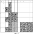
- the primary 20 MHz channel is on a 20 MHz channel that is numbered by using an odd number (shown in FIG. 17a )
- the other part of the HE-SIG-B may be obtained by using a 20 MHz channel, which is numbered by using an even number, of the secondary 40 MHz channel.
- the other part of the HE-SIG-B may be obtained by using a 20 MHz channel, which is numbered by using an odd number, of the secondary 40 MHz channel.
- the primary 20 MHz channel and the secondary 20 MHz channel include an HE-SIG-B 1 and an HE-SIG-B 2
- the secondary 40 MHz channel also includes the HE-SIG-B 1 and the HE-SIG-B 2
- the receiving station may determine by itself from which to obtain the HE-SIG-B 1 and the HE-SIG-B 2.
- a secondary 80 MHz channel is divided into two continuous 40 MHz channels, and the two 40 MHz channels may be classified according to different rules.
- the two 40 MHz channels are classified into an upper 40 MHz channel (a 40 MHz channel having a higher frequency) and a lower 40 MHz channel (a 40 MHz channel having a lower frequency) according to frequencies.
- the two 40 MHz channels are classified into a near 40 MHz channel and a far 40 MHz channel according to distances to the primary 20 MHz channel.
- a classification rule is not limited in this patent solution, and an indication principle thereof is similar.
- an example of the upper 40 MHz channel and the lower 40 MHz channel is used in descriptions of subsequent embodiments for description.
- indication is performed by using both a BW field (two bits) and a CB field (one bit).
- ⁇ BW, CB ⁇ has eight indication manners in total: ⁇ 0, 0 ⁇ , ⁇ 0, 1 ⁇ , ⁇ 1, 0 ⁇ , ⁇ 1, 1 ⁇ , ⁇ 2, 0 ⁇ , ⁇ 2, 1 ⁇ , ⁇ 3, 0 ⁇ , and ⁇ 3, 1 ⁇ , as shown in Table 2.
- one or more indication manners may be randomly selected from the eight indication manners without repetition.
- a corresponding manner shown in Table 2 is recommended in this embodiment.
- Another manner of corresponding between an indication manner and a channel mode is also applicable to this embodiment.
- FIG. 18b shows another implementation, and the implementation includes the following six channel modes:
- indication is performed by using both a BW field (two bits) and a CB field (one bit).
- ⁇ BW, CB ⁇ has eight indication manners in total: ⁇ 0, 0 ⁇ , ⁇ 0, 1 ⁇ , ⁇ 1, 0 ⁇ , ⁇ 1, 1 ⁇ , ⁇ 2, 0 ⁇ , ⁇ 2, 1 ⁇ , ⁇ 3, 0 ⁇ , and ⁇ 3, 1 ⁇ , as shown in Table 3.
- one or more indication manners may be randomly selected from the eight indication manners without repetition.
- a corresponding manner shown in Table 3 is recommended in this embodiment.
- Another manner of corresponding between an indication manner and a channel mode is also applicable to this embodiment.
- FIG. 18c shows another implementation, and the implementation includes the following seven channel modes:
- indication is performed by using both a BW field (two bits) and a CB field (one bit).
- ⁇ BW, CB ⁇ has eight indication manners in total: ⁇ 0, 0 ⁇ , ⁇ 0, 1 ⁇ , ⁇ 1, 0 ⁇ , ⁇ 1, 1 ⁇ , ⁇ 2, 0 ⁇ , ⁇ 2, 1 ⁇ , ⁇ 3, 0 ⁇ , and ⁇ 3, 1 ⁇ , as shown in Table 4.
- one or more indication manners may be randomly selected from the eight indication manners without repetition.
- a corresponding manner shown in Table 4 is described in this embodiment. Another manner of corresponding between an indication manner and a channel mode is also applicable to this embodiment.
- FIG. 18d shows another implementation, and the implementation includes the following eight channel modes:
- indication is performed by using both a BW field (two bits) and a CB field (one bit).
- ⁇ BW, CB ⁇ has eight indication manners in total: ⁇ 0, 0 ⁇ , ⁇ 0, 1 ⁇ , ⁇ 1, 0 ⁇ , ⁇ 1, 1 ⁇ , ⁇ 2, 0 ⁇ , ⁇ 2, 1 ⁇ , ⁇ 3, 0 ⁇ , and ⁇ 3, 1 ⁇ , as shown in Table 5.
- one or more indication manners may be randomly selected from the eight indication manners without repetition.
- a corresponding manner shown in Table 5 is described in this embodiment. Another manner of corresponding between an indication manner and a channel mode is also applicable to this embodiment.
- a secondary 40 MHz channel is divided into two 20 MHz channels.
- the two 20 MHz channels may be classified according to different rules. For example, the two 20 MHz channels are classified into an upper 20 MHz channel (a 20 MHz channel having a higher frequency) and a lower 20 MHz channel (a 20 MHz channel having a lower frequency) according to frequencies. For another example, the two 20 MHz channels are classified into a near 20 MHz channel and a far 20 MHz channel according to distances to the primary 20 MHz channel.
- a classification rule is not limited in this patent solution, and an indication principle thereof is similar. For convenience, an example of the upper 20 MHz channel and the lower 20 MHz channel is used in descriptions of subsequent embodiments for description. In the implementation 9, there are following six bandwidth modes shown in FIG. 19 :
- the 20 MHz channel when the primary 20 MHz channel is on a channel, which is numbered by using an odd number, in descending order of frequencies, the 20 MHz channel is a 20 MHz channel, which is numbered by using an even number, of the secondary 40 MHz channel.
- the 20 MHz channel is a 20 MHz channel, which is numbered by using an odd number, of the secondary 40 MHz channel.
- Mode 4 a primary 20 MHz channel, a secondary 20 MHz channel, and a lower 20 MHz channel of secondary 40 MHz channel; or a primary 20 MHz channel, a secondary 20 MHz channel, and an upper 20 MHz channel of secondary 40 MHz channel; or a primary 20 MHz channel, a secondary 20 MHz channel, and a secondary 40 MHz channel.
- Mode 5 a primary 20 MHz channel and a secondary 80 MHz channel; or a primary 20 MHz channel, a lower 20 MHz channel of secondary 40 MHz channel, and a secondary 80 MHz channel; or a primary 20 MHz channel, an upper 20 MHz channel of secondary 40 MHz channel, and a secondary 80 MHz channel; or a primary 20 MHz channel, a secondary 40 MHz channel, and a secondary 80 MHz channel.
- Mode 6 a primary 20 MHz channel, a secondary 20 MHz channel, and a secondary 80 MHz channel; or a primary 20 MHz channel, a secondary 20 MHz channel, a lower 20 MHz channel of secondary 40 MHz channel, and a secondary 80 MHz; or a primary 20 MHz channel, a secondary 20 MHz channel, an upper 20 MHz channel of secondary 40 MHz channel, and a secondary 80 MHz channel; or a primary 20 MHz channel, a secondary 20 MHz channel, a secondary 40 MHz channel, and a secondary 80 MHz channel.
- indication is performed by using both a BW field (two bits) and a CB field (one bit).
- ⁇ BW, CB ⁇ has eight indication manners in total: ⁇ 0, 0 ⁇ , ⁇ 0, 1 ⁇ , ⁇ 1, 0 ⁇ , ⁇ 1, 1 ⁇ , ⁇ 2, 0 ⁇ , ⁇ 2, 1 ⁇ , ⁇ 3, 0 ⁇ , and ⁇ 3, 1 ⁇ , as shown in Table 6.
- one or more indication manners may be randomly selected from the eight indication manners without repetition.
- a corresponding manner shown in Table 6 is described in this embodiment. Another manner of corresponding between an indication manner and a channel mode is also applicable to this embodiment.
- a secondary 40 MHz channel is divided into two 20 MHz channels, and a secondary 80 MHz channel is divided into two continuous 40 MHz channels.
- the two 20 MHz channels and the two 40 MHz channels that are obtained after division are respectively an upper 20 MHz channel, a lower 20 MHz channel, an upper 40 MHz channel, and a lower 40 MHz channel is used in descriptions of subsequent embodiments for description.
- indication is performed by using both a BW field (two bits) and a CB field (one bit).
- ⁇ BW, CB ⁇ has eight indication manners in total: ⁇ 0, 0 ⁇ , ⁇ 0, 1 ⁇ , ⁇ 1, 0 ⁇ , ⁇ 1, 1 ⁇ , ⁇ 2, 0 ⁇ , ⁇ 2, 1 ⁇ , ⁇ 3, 0 ⁇ , and ⁇ 3, 1 ⁇ , as shown in Table 7.
- one or more indication manners may be randomly selected from the eight indication manners without repetition.
- a corresponding manner shown in Table 7 is described in this embodiment. Another manner of corresponding between an indication manner and a channel mode is also applicable to this embodiment.
- FIG. 20b shows another implementation, and the implementation includes the following six channel modes:
- the 20 MHz channel when the primary 20 MHz channel is on a channel, which is numbered by using an odd number, in descending order of frequencies, the 20 MHz channel is a 20 MHz channel, which is numbered by using an even number, of the secondary 40 MHz channel.
- the 20 MHz channel is a 20 MHz channel, which is numbered by using an odd number, of the secondary 40 MHz channel.
- Mode 4 a primary 20 MHz channel, a secondary 20 MHz channel, and a lower 20 MHz channel of secondary 40 MHz channel; or a primary 20 MHz channel, a secondary 20 MHz channel, and an upper 20 MHz channel of secondary 40 MHz channel; or a primary 20 MHz channel, a secondary 20 MHz channel, and a secondary 40 MHz channel.
- Mode 5 a primary 20 MHz channel and an upper 40 MHz channel of secondary 80 MHz channel; or a primary 20 MHz channel, an upper 20 MHz channel of secondary 40 MHz channel, and an upper 40 MHz channel of secondary 80 MHz channel; or a primary 20 MHz channel, a lower 20 MHz channel of secondary 40 MHz channel, and an upper 40 MHz channel of secondary 80 MHz channel; or a primary 20 MHz channel and a secondary 80 MHz channel; or a primary 20 MHz channel, a secondary 40 MHz channel, and an upper 40 MHz channel of secondary 80 MHz channel; or a primary 20 MHz channel, an upper 20 MHz channel of secondary 40 MHz channel, and a secondary 80 MHz channel; or a primary 20 MHz channel, a lower 20 MHz channel of secondary 40 MHz channel, and a secondary 80 MHz channel; or a primary 20 MHz channel, a secondary 40 MHz channel, and a secondary 80 MHz channel.
- Mode 6 a primary 20 MHz channel, a secondary 20 MHz channel, and a lower 40 MHz channel of secondary 80 MHz channel; or a primary 20 MHz channel, a secondary 20 MHz channel, an upper 20 MHz channel of secondary 40 MHz channel, and a lower 40 MHz channel of secondary 80 MHz channel; or a primary 20 MHz channel, a secondary 20 MHz channel, a lower 20 MHz channel of secondary 40 MHz channel, and a lower 40 MHz channel of secondary 80 MHz channel; or a primary 20 MHz channel, a secondary 20 MHz channel, and a secondary 80 MHz channel; or a primary 20 MHz channel, a secondary 20 MHz channel, a secondary 40 MHz channel, and a lower 40 MHz channel of secondary 80 MHz channel; or a primary 20 MHz channel, a secondary 20 MHz channel, an upper 20 MHz channel of secondary 40 MHz channel, and a secondary 80 MHz channel; or a primary 20 MHz channel, a secondary 20 MHz channel, a lower 20 MHz channel of
- indication is performed by using both a BW field (two bits) and a CB field (one bit).
- ⁇ BW, CB ⁇ has eight indication manners in total: ⁇ 0, 0 ⁇ , ⁇ 0, 1 ⁇ , ⁇ 1, 0 ⁇ , ⁇ 1, 1 ⁇ , ⁇ 2, 0 ⁇ , ⁇ 2, 1 ⁇ , ⁇ 3, 0 ⁇ , and ⁇ 3, 1 ⁇ , as shown in Table 8.
- one or more indication manners may be randomly selected from the eight indication manners without repetition.
- a corresponding manner shown in Table 8 is described in this embodiment. Another manner of corresponding between an indication manner and a channel mode is also applicable to this embodiment.
- FIG. 20c shows another implementation, and the implementation includes the following seven channel modes:
- indication is performed by using both a BW field (two bits) and a CB field (one bit).
- ⁇ BW, CB ⁇ has eight indication manners in total: ⁇ 0, 0 ⁇ , ⁇ 0, 1 ⁇ , ⁇ 1, 0 ⁇ , ⁇ 1, 1 ⁇ , ⁇ 2, 0 ⁇ , ⁇ 2, 1 ⁇ , ⁇ 3, 0 ⁇ , and ⁇ 3, 1 ⁇ , as shown in Table 9.
- one or more indication manners may be randomly selected from the eight indication manners without repetition.
- a corresponding manner shown in Table 9 is described in this embodiment. Another manner of corresponding between an indication manner and a channel mode is also applicable to this embodiment.
- FIG. 20d shows another implementation, and the implementation includes the following eight channel modes:
- the 20 MHz channel when the primary 20 MHz channel is on a channel, which is numbered by using an odd number, in descending order of frequencies, the 20 MHz channel is a 20 MHz channel, which is numbered by using an even number, of the secondary 40 MHz channel.
- the 20 MHz channel is a 20 MHz channel, which is numbered by using an odd number, of the secondary 40 MHz channel.
- Mode 4 a primary 20 MHz channel, a secondary 20 MHz channel, and a lower 20 MHz channel of secondary 40 MHz channel; or a primary 20 MHz channel, a secondary 20 MHz channel, and an upper 20 MHz channel of secondary 40 MHz channel; or a primary 20 MHz channel, a secondary 20 MHz channel, and a secondary 40 MHz channel.
- Mode 5 a primary 20 MHz channel and a lower 40 MHz channel of secondary 80 MHz channel; or a primary 20 MHz channel, an upper 20 MHz channel of secondary 40 MHz channel, and a lower 40 MHz channel of secondary 80 MHz channel; or a primary 20 MHz channel, a lower 20 MHz channel of secondary 40 MHz channel, and a lower 40 MHz channel of secondary 80 MHz channel; or a primary 20 MHz channel and a secondary 80 MHz channel; or a primary 20 MHz channel, a secondary 40 MHz channel, and a lower 40 MHz channel of secondary 80 MHz channel; or a primary 20 MHz channel, an upper 20 MHz channel of secondary 40 MHz channel, and a secondary 80 MHz channel; or a primary 20 MHz channel, a lower 20 MHz channel of secondary 40 MHz channel, and a secondary 80 MHz channel; or a primary 20 MHz channel, a secondary 40 MHz channel, and a secondary 80 MHz channel; or a primary 20 MHz channel, a secondary 40 MHz channel,
- Mode 6 a primary 20 MHz channel, a secondary 20 MHz channel, and a lower 40 MHz channel of secondary 80 MHz channel; or a primary 20 MHz channel, a secondary 20 MHz channel, an upper 20 MHz channel of secondary 40 MHz channel, and a lower 40 MHz channel of secondary 80 MHz channel; or a primary 20 MHz channel, a secondary 20 MHz channel, a lower 20 MHz channel of secondary 40 MHz channel, and a lower 40 MHz channel of secondary 80 MHz channel; or a primary 20 MHz channel, a secondary 20 MHz channel, and a secondary 80 MHz channel; or a primary 20 MHz channel, a secondary 20 MHz channel, a secondary 40 MHz channel, and a lower 40 MHz channel of secondary 80 MHz channel; or a primary 20 MHz channel, a secondary 20 MHz channel, an upper 20 MHz channel of secondary 40 MHz channel, and a secondary 80 MHz channel; or a primary 20 MHz channel, a secondary 20 MHz channel, a lower 20 MHz channel of
- Mode 7 a primary 20 MHz channel and an upper 40 MHz channel of secondary 80 MHz channel; or a primary 20 MHz channel, an upper 20 MHz channel of secondary 40 MHz channel, and an upper 40 MHz channel of secondary 80 MHz channel; or a primary 20 MHz channel, a lower 20 MHz channel of secondary 40 MHz channel, and an upper 40 MHz channel of secondary 80 MHz channel; or a primary 20 MHz channel, a lower 20 MHz channel of secondary 40 MHz channel, and an upper 40 MHz channel of secondary 80 MHz channel.
- Mode 8 a primary 20 MHz channel and a 20 MHz channel of a secondary 40 MHz channel.
- the 20 MHz channel is a 20 MHz channel, which is numbered by using an odd number, of the secondary 40 MHz channel.
- the 20 MHz channel is a 20 MHz channel, which is numbered by using an even number, of the secondary 40 MHz channel.
- indication is performed by using both a BW field (two bits) and a CB field (one bit).
- ⁇ BW, CB ⁇ has eight indication manners in total: ⁇ 0, 0 ⁇ , ⁇ 0, 1 ⁇ , ⁇ 1, 0 ⁇ , ⁇ 1, 1 ⁇ , ⁇ 2, 0 ⁇ , ⁇ 2, 1 ⁇ , ⁇ 3, 0 ⁇ , and ⁇ 3, 1 ⁇ , as shown in Table 10.
- one or more indication manners may be randomly selected from the eight indication manners without repetition.
- a corresponding manner shown in Table 10 is described in this embodiment. Another manner of corresponding between an indication manner and a channel mode is also applicable to this embodiment.
- This embodiment of the present invention provides a method for indicating a channel in a wireless local area network WLAN.
- a sending station generates and sends a physical protocol data unit PPDU, the PPDU includes a preamble field and a data field, a high efficiency signal field HE-SIG-A of the preamble field includes a bandwidth identifier and a channel bonding identifier, and the channel bonding identifier is used to indicate whether a data transmission channel is continuous in a frequency domain.
- a discontinuous channel in a frequency domain in a wireless local area network is indicated, an available data transmission channel is improved, and a system throughput is increased.
- Embodiment 2 of the present invention provides a method, which is applied to a WLAN, for indicating a channel.
- the method may be applied to a station, for example, the AP and the STA 1 to the STA 3 in FIG. 2 .
- the station may support a next-generation WLAN standard, for example, the 802.11ax standard.
- FIG. 21 is an example block diagram of the method for indicating a channel. Specific steps are as follows:
- Step 201 Generate a physical protocol data unit PPDU, where the PPDU includes a preamble field and a data field, a high efficiency signal field HE-SIG-A of the preamble field includes a bandwidth identifier and a secondary 20 MHz channel identifier, and when the bandwidth identifier indicates that a bandwidth of a data transmission channel is greater than 40 MHz, the secondary 20 MHz channel identifier is used to indicate whether a secondary 20 MHz channel is available.
- a physical protocol data unit PPDU where the PPDU includes a preamble field and a data field, a high efficiency signal field HE-SIG-A of the preamble field includes a bandwidth identifier and a secondary 20 MHz channel identifier, and when the bandwidth identifier indicates that a bandwidth of a data transmission channel is greater than 40 MHz, the secondary 20 MHz channel identifier is used to indicate whether a secondary 20 MHz channel is available.
- Step 202 Send the PPDU.
- the secondary 20 MHz channel identifier includes at least one bit, and one bit is used as an example below for description. If the secondary 20 MHz channel identifier is a first value, the secondary 20 MHz channel is unavailable; or if the secondary 20 MHz channel identifier is a second value, the secondary 20 MHz channel is available.
- first value and the second value of the secondary 20 MHz channel identifier are not limited in the present invention.
- the first value is “0” and the second value is “1”.
- the first value is "1" and the second value is “0".
- the foregoing two cases are both in the protection scope of the present invention.
- the case in which the first value is “0” and the second value is “1” is specifically used below for description.
- the sending station indicates the data transmission channel by using the bandwidth identifier and the secondary 20 MHz channel identifier.
- the data transmission channel includes a primary 20 MHz channel
- the bandwidth identifier includes at least two bits and the secondary 20 MHz channel identifier includes at least one bit.
- the bandwidth identifier includes two bits and the secondary 20 MHz channel identifier includes one bit is used for description in this embodiment.
- a data transmission bandwidth channel is a primary 20 MHz channel, that is, a channel 0.
- a value of a channel bonding identifier may be 0, 1, or reserved.
- the data transmission channel includes a primary 20 MHz channel and a secondary 20 MHz channel, that is, the channel 0 and a channel 1.
- the value of the channel bonding identifier may be 0, 1, or reserved.
- the data transmission channel includes a primary 20 MHz channel and a secondary 40 MHz channel, that is, the channel 0, a channel 2, and a channel 3.
- the data transmission channel includes a primary 20 MHz channel, a secondary 20 MHz channel, and a secondary 40 MHz channel, that is, the channels 0 to 3.
- the data transmission channel includes a primary 20 MHz channel and a secondary 80 MHz channel, that is, the channel 0 and channels 4 to 7.
- the data transmission channel includes a primary 20 MHz channel, a secondary 40 MHz channel, and a secondary 80 MHz channel, that is, the channels 0 and 2 to 7.
- the data transmission channel includes a primary 20 MHz channel, a secondary 20 MHz channel, a secondary 40 MHz channel, and a secondary 80 MHz channel, that is, the channels 0 to 7.
- the data transmission channel includes a primary 20 MHz channel, a secondary 20 MHz channel, and a secondary 80 MHz channel, that is, the channels 0, 1, and 4 to 7.
- This embodiment of the present invention provides a method for indicating a channel in a wireless local area network WLAN.
- a sending station generates and sends a physical protocol data unit PPDU, the PPDU includes a preamble field and a data field, a high efficiency signal field HE-SIG-A of the preamble field includes a bandwidth identifier and a secondary 20 MHz channel identifier, and when the bandwidth identifier indicates that a data transmission channel is greater than 40 MHz, the secondary 20 MHz channel identifier is used to indicate whether a secondary 20 MHz channel is available.
- a discontinuous channel in a frequency domain in a wireless local area network is indicated, an available data transmission channel is improved, and a system throughput is increased.
- Embodiment 3 of the present invention provides a method, which is applied to a WLAN, for indicating a channel.
- the method may be applied to a station, for example, the AP and the STA 1 to the STA 3 in FIG. 2 .
- the station may support a next-generation WLAN standard, for example, the 802.11ax standard.
- a data transmission channel is indicated by using a bandwidth identifier in a PPDU, and the bandwidth (BW) identifier includes at least two bits.
- the current data transmission channel includes a primary 20 MHz channel and a secondary 20 MHz channel.
- the current data transmission channel includes a primary 20 MHz channel and a secondary 40 MHz channel; or includes a primary 20 MHz channel, a secondary 20 MHz channel, and a secondary 40 MHz channel.
- a current data transmission channel includes a primary 20 MHz channel and a secondary 80 MHz channel; or includes a primary 20 MHz channel, a secondary 20 MHz channel, and a secondary 80 MHz channel; or includes a primary 20 MHz channel, a secondary 40 MHz channel, and a secondary 80 MHz channel; or includes a primary 20 MHz channel, a secondary 20 MHz channel, a secondary 40 MHz channel, and a secondary 80 MHz channel.
- either of an HE-SIG-B 1 and an HE-SIG-B 2 may be obtained by using a primary 20 MHz channel, and the other part of an HE-SIG-B is obtained by using a 20 MHz channel of secondary 40 MHz.
- specific frequencies are arranged in descending order, when the primary 20 MHz channel is on a 20 MHz channel that is numbered by using an odd number, the other part of the HE-SIG-B may be obtained by using a 20 MHz channel, which is numbered by using an even number, of the secondary 40 MHz channel.
- the other part of the HE-SIG-B may be obtained by using a 20 MHz channel, which is numbered by using an odd number, of the secondary 40 MHz channel.
- either of an HE-SIG-B 1 and an HE-SIG-B 2 may be obtained by using a primary 20 MHz channel, and the other part of an HE-SIG-B is obtained by using a 20 MHz channel of secondary 80 MHz.
- specific frequencies are arranged in descending order, when the primary 20 MHz channel is on a 20 MHz channel that is numbered by using an odd number, the other part of the HE-SIG-B may be obtained by using any 20 MHz channel, which is numbered by using an even number, of the secondary 80 MHz channel.
- the other part of the HE-SIG-B may be obtained by using any 20 MHz channel, which is numbered by using an odd number, of the secondary 80 MHz channel.
- This embodiment of the present invention provides a method for indicating a channel in a wireless local area network WLAN.
- a sending station generates and sends a physical protocol data unit PPDU, the PPDU includes a preamble field and a data field, and a high efficiency signal field HE-SIG-A of the preamble field includes a bandwidth identifier.
- a discontinuous channel in a frequency domain in a wireless local area network is indicated, an available data transmission channel is improved, and a system throughput is increased.
- FIG. 24 is a schematic block diagram of an apparatus for indicating a channel in a wireless local area network according to Embodiment 4 of the present invention.
- the apparatus is, for example, an access point, or a dedicated circuit or a chip implementing a related function.
- the access point 1000 includes a processor 1010, a memory 1020, a baseband circuit 1030, a radio frequency circuit 1040, and an antenna 1050.
- the apparatus may be the AP shown in FIG. 2 .
- the AP communicates with a STA 1, a STA 2, and a STA 3.
- the processor 1010 controls operations of the access point 1000.
- the memory 1020 may include a read-only memory and a random access memory, and provide instructions and data to the processor 1010.
- the processor may be a general purpose processor, a digital signal processor, an application-specific integrated circuit, a field programmable gate array, or another programmable logic device. A part of the memory 1020 may further include a non-volatile random access memory (NVRAM).
- the baseband circuit 1030 is configured to generate a to-be-transmitted baseband signal, or to decode a received baseband signal.
- the radio frequency circuit 1040 is configured to modulate a low-frequency baseband signal to a high-frequency carrier signal, and the high-frequency carrier signal is transmitted by using the antenna 1050.
- the radio frequency circuit is also configured to demodulate a high-frequency signal received by the antenna 1050 to a low-frequency carrier signal.
- the components of the access point 1000 are coupled together by using a bus system 1060.
- the bus system 1060 includes a power bus, a control bus, and a status signal bus.
- various buses in the figure are marked as the bus system 1060. It should be noted that the foregoing descriptions of the access point structure may be applied to subsequent embodiments.
- the baseband circuit 1030 is configured to generate a physical protocol data unit PPDU, where the PPDU includes a preamble field and a data field, a high efficiency signal field HE-SIG-A of the preamble field includes a bandwidth identifier and a channel bonding identifier, and the channel bonding identifier is used to indicate whether a data transmission channel is continuous in a frequency domain.
- PPDU physical protocol data unit
- HE-SIG-A of the preamble field includes a bandwidth identifier and a channel bonding identifier
- the channel bonding identifier is used to indicate whether a data transmission channel is continuous in a frequency domain.
- the radio frequency circuit 1040 is configured to send the PPDU.
- the data transmission channel is continuous in the frequency domain; or if the channel bonding identifier is a second value, the data transmission channel includes multiple discontinuous channels in the frequency domain.
- the apparatus for indicating a channel indicates the data transmission channel by using both the bandwidth identifier and the channel bonding identifier, and indication manners are specifically as follows:
- the data transmission channel includes a primary 20 MHz channel
- the data transmission channel includes a primary 20 MHz channel
- the data transmission channel includes a primary 20 MHz channel
- the data transmission channel includes a primary 20 MHz channel
- the data transmission channel includes a primary 20 MHz channel
- Embodiment 1 to Embodiment 3 are also applied to the apparatus for indicating a channel in Embodiment 4.
- This embodiment of the present invention provides an apparatus for indicating a channel in a wireless local area network WLAN.
- a baseband circuit generates a physical protocol data unit PPDU, the PPDU includes a preamble field and a data field, a high efficiency signal field HE-SIG-A of the preamble field includes a bandwidth identifier and a secondary 20 MHz channel identifier, and when the bandwidth identifier indicates that a data transmission channel is greater than 40 MHz, the secondary 20 MHz channel identifier is used to indicate whether a secondary 20 MHz channel is available.
- a discontinuous channel in a frequency domain in a wireless local area network is indicated, an available data transmission channel is improved, and a system throughput is increased.
- Embodiment 5 of the present invention provides a method, which is applied to a WLAN, for indicating a channel.
- the method may be applied to a station, for example, the AP and the STA 1 to the STA 3 in FIG. 2 .
- the station may support a next-generation WLAN standard, for example, the 802.11ax standard.
- a data transmission channel is indicated by using a bandwidth identifier in a PPDU, and the bandwidth (BW) identifier includes at least three bits.
- the data transmission channel includes the following eight modes:
- the first 20 MHz channel and the second 20 MHz channel may be defined by using different methods, and this is not limited in this patent.
- the first 20 MHz channel is a 20 MHz channel, which has a lower frequency, of the two 20 MHz channels, and locations of the two 20MHz channels of the secondary 80 MHz channel are opposite parity comparing with the location of the primary 20 MHz channel
- the second 20 MHz channel is a 20 MHz channel, which has a higher frequency, of the two 20 MHz channels, and locations of the two 20MHz channels of the secondary 80 MHz channel are opposite parity comparing with the location of the primary 20 MHz channel.
- a contrary case is also applicable.
- the first 20 MHz channel is a 20 MHz channel, whose rate of frequency separation to the primary 20 MHz channel is smaller, of the two 20 MHz channels of the secondary 80 MHz channel, and locations of the two 20MHz channels are opposite parity comparing with the location of the primary 20 MHz channel
- the second 20 MHz channel is a 20 MHz channel, whose rate of frequency separation to the primary 20 MHz channel is larger, of the two 20 MHz channels of the secondary 80 MHz channel, and locations of the two 20MHz channels are opposite parity comparing with the location of the primary 20 MHz channel.
- a contrary case is also applicable.
- a channel is a primary 20 MHz channel and a 20 MHz channel of secondary 40 MHz, whose location is the same parity as that of the primary 20 MHz channel
- mode 3 or mode 4 may be indicated.
- the channel includes the primary 20 MHz channel and at least one 20 MHz channel of secondary 80 MHz, but does not include any 20 MHz channel whose location is opposite parity comparing with that of the primary 20 MHz channel, mode 5, 6, 7, or 8 may be indicated.
- mode 5, 6, 7, or 8 may be indicated.
- a receiving station when receiving a part of an HE-SIG-B on the primary 20 MHz channel, a receiving station attempts to receive the other part of the HE-SIG-B on the 20 MHz channel whose location is opposite parity comparing with that of the primary 20 MHz channel and that is indicated in the mode, but the receiving fails. No information related to the HE-SIG-B is transmitted on the 20 MHz channel whose location is opposite parity comparing with that of the primary 20 MHz channel. Therefore, the receiving failure does not bring any information loss.
- a correspondence between a bandwidth identifier and the eight modes is not limited in the present invention, and the following corresponding manner is preferably selected: Bandwidth identifier 000 001 010 011 100 101 110 111 Mode Mode 1 Mode 2 Mode 3 Mode 4 Mode 5 Mode 6 Mode 7 Mode 8
- Table 11 Mode Bandwidth range of a channel Actually used channel 1 20 MHz 0 2 40 MHz (0, 1) 3 80 MHz (0, 1, 2) (0, 1, 3) (0, 1, 2, 3) 4 80 MHz (0, 3) (0, 1, 3) (0, 2, 3) (0, 1, 2, 3) Notes: (0, 2) belongs to mode 3 or mode 4.
- the channel identifier used in the table is a logical identifier of the channel.
- a channel identifier 0 indicates a primary 20 MHz channel
- a channel identifier 1 indicates a secondary 20 MHz channel
- channel identifiers 2 and 3 indicate a secondary 40 MHz channel
- channel identifiers 4 to 7 indicate a secondary 80 MHz channel.
- a frequently used mapping relationship between a channel identifier and a channel is described above. Another mapping relationship between a channel identifier and a channel also exists. This is not limited in the present invention.
- an HE-SIG-B on a primary channel is referred to as an HE-SIG-B 1 herein.
- the HE-SIG-B 1 is copied on a channel whose location is the same parity as that of the primary channel, and a common part of the HE-SIG-B 1 includes RU allocation signaling of a primary 20 MHz channel and a 20 MHz channel whose location is the same parity as that of the primary channel.
- a common part of an HE-SIG-B 2 includes RU allocation signaling of a 20 MHz channel whose location is opposite parity comparing with that of the primary 20MHz channel, and is copied on the multiple 20 MHz channels. It is assumed that RU allocation signaling of each 20 MHz channel has a length of N bits, and eight bits is used as an example in the following descriptions.
- the first piece of information indicates a length of the common part of the HE-SIG-B 1 and a length of the common part of the HE-SIG-B 2 to a receiving node (herein, the length of the common part of the HE-SIG-B 1 is equal to the length of the common part of the HE-SIG-B 2).
- the second piece of information indicates on which 20 MHz channel the receiving node receives the HE-SIG-B 2. It should be noted herein that the receiving node is bound to receive the HE-SIG-B 1 on the primary 20 MHz channel.
- mode 3 indicates to the receiving node that both the length of the common part of the HE-SIG-B 1 and the length of the common part of the HE-SIG-B 2 are 16 bits (statistics on a length of RU allocation signaling of only a 20 MHz channel is collected herein), and the HE-SIG-B 2 is received on a channel whose logical identifier is 1.
- mode 8 indicates to the receiving node that both the length of the common part of the HE-SIG-B 1 and the length of the common part of the HE-SIG-B 2 are 32 bits, and the HE-SIG-B 2 is received on a 20 M channel whose logical identifier is 7. Therefore, the foregoing eight modes indicate that the receiving node can correctly receive the HE-SIG-B 1 and the HE-SIG-B 2.
- special RU allocation signaling that is, 242(0), exists in the RU allocation signaling of an HE-SIG-B 20 MHz channel, and indicates that 242 subcarriers that can transmit information and that correspond to the 20 MHz channel do not transmit data of any station. That is, the 20 MHz channel does not perform data transmission.
- the receiving node can learn that data is received on which channels. For example, it is assumed that a data transmission channel is (0 1 2), and a sending node sets a bandwidth identifier bit of an HE-SIG-A in a physical layer preamble to mode 3.
- the HE-SIG-B 1 includes RU allocation signaling of a channel 0 and a channel 2
- the HE-SIG-B 2 includes RU allocation signaling of a channel 1 and a channel 3.
- the RU allocation signaling of the channel 3 is 242(0).
- a receiver After receiving the HE-SIG-A, a receiver learns, according to the bandwidth identifier bit, that mode 3 is used. That is, both the length of the common part of the HE-SIG-B 1 and the length of the common part of the HE-SIG-B 2 are 16 bits.
- the HE-SIG-B 1 is received on a channel whose logical identifier is 0 (the primary 20 MHz channel), and the HE-SIG-B 2 is received on a channel whose logical identifier is 1.
- the RU allocation signaling 242(0) which is included in the HE-SIG-B 2, of the channel whose logical identifier is 3, it is learned that the data transmission channel is (0 1 2).
- actually used channels indicated in each mode in Table 11 are overlapped. However, this does not affect that the receiving node learns a length of a common part of an HE-SIG-B and learns that the HE-SIG-B 2 is received on which 20 MHz channel. Therefore, the foregoing mode indication may correctly tell the receiving node that data transmission is performed on which 20 MHz channels.
- the actually used channels that are overlapped are used in only one mode, so that actually used channels indicated in all the modes are not overlapped. For example, cases in which actually used channels that are overlapped and that are indicated in mode 3 and mode 4 in Table 11 are (0, 1, 3), (0, 1, 2, 3), and (0, 2). To avoid overlapping, the foregoing three cases of actually used channels are used only in mode 3, and are removed from mode 4. It should be noted that the foregoing channel overlapping cases are also applicable to another embodiment.
- channel identifiers in Table 11 do not affect actually used channels. For example, actually used channels indicated by channel identifiers (0, 7, 1, 2) and channel identifiers (0, 1, 2, 7) are the same.
- This embodiment of the present invention provides a method for indicating a channel in a wireless local area network WLAN.
- a sending station generates and sends a physical protocol data unit PPDU, the PPDU includes a preamble field and a data field, a high efficiency signal field HE-SIG-A of the preamble field includes a bandwidth identifier, and the bandwidth identifier is used to indicate a data transmission channel.
- a discontinuous channel in a frequency domain in a wireless local area network is indicated, an available data transmission channel is improved, and a system throughput is increased.
- Embodiment 6 of the present invention provides a method, which is applied to a WLAN, for indicating a channel.
- the method may be applied to a station, for example, the AP and the STA 1 to the STA 3 in FIG. 2 .
- the station may support a next-generation WLAN standard, for example, the 802.11ax standard.
- a data transmission channel is indicated by using a bandwidth identifier in a PPDU, and the bandwidth (BW) identifier includes at least three bits.
- the data transmission channel includes the following eight modes:
- bandwidth identifier 000 001 010 011 100 101 110 111 Mode Mode 1 Mode 2 Mode 3 Mode 4 Mode 5 Mode 6 Mode 7 Mode 8
- Table 12 Mode Bandwidth range of a channel Actually used channel 1 20 MHz (0) 2 40 MHz (0,1) 3 80 MHz (0, 1, 2) (0, 1, 3) (0, 1, 2, 3) 4 80 MHz (0, 3) (0, 1, 3) (0, 2, 3) (0, 1, 2, 3) 5 80 MHz (0, 2) 6 160 MHz (0,1,4) (0, 1, 2, 4) (0, 1, 5) (0, 1, 2, 5) (0, 1, 6) (0, 1, 2, 6) (0, 1, 7) (0, 1, 2, 7) (0, 1, 4, 5) (0, 1, 2, 4, 5) (0, 1, 4, 6) (0, 1, 2, 4, 6) (0, 1, 4, 7) (0, 1, 2,4,7) (0, 1, 5, 6) (0, 1, 2, 5, 6) (0, 1, 5, 7) (0, 1, 2, 5, 7) (0, 1, 2, 6, 7) (0, 1, 4, 5, 7) (0, 1, 2, 6, 7) (0, 1, 4, 5, 6) (0, 1, 4, 5, 7) (0, 1, 2, 4, 5, 7) (0, 1, 4, 6, 7) (0, 1, 4, 6, 7) (0, 1, 4, 5, 7) (0,
- the channel identifier used in the table is a logical identifier of the channel.
- a channel identifier 0 indicates a primary 20 MHz channel
- a channel identifier 1 indicates a secondary 20 MHz channel
- channel identifiers 2 and 3 indicate a secondary 40 MHz channel
- channel identifiers 4 to 7 indicate a secondary 80 MHz channel.
- a frequently used mapping relationship between a channel identifier and a channel is described above. Another mapping relationship between a channel identifier and a channel also exists. This is not limited in the present invention.
- channel identifiers in Table 12 do not affect actually used channels. For example, actually used channels indicated by channel identifiers (0, 7, 1, 2) and channel identifiers (0, 1, 2, 7) are the same.
- the HE-SIG-B includes RU allocation signaling of all 20 M channels. Only one piece of information, that is, a length of the HE-SIG-B, is carried in mode 5 and mode 8. In the other modes other than mode 5 and mode 8, RU allocation signaling included in common parts of the HE-SIG-B 1 and the HE-SIG-B 2 are the same as those in the transmission manner in Embodiment 5. Descriptions of overlapping cases indicated in the modes in the table are the same as those in Embodiment 5, and details are not described herein again.
- This embodiment of the present invention provides a method for indicating a channel in a wireless local area network WLAN.
- a sending station generates and sends a physical protocol data unit PPDU, the PPDU includes a preamble field and a data field, a high efficiency signal field HE-SIG-A of the preamble field includes a bandwidth identifier, and the bandwidth identifier is used to indicate a data transmission channel.
- a discontinuous channel in a frequency domain in a wireless local area network is indicated, an available data transmission channel is improved, and a system throughput is increased.
- Embodiment 7 of the present invention provides a method, which is applied to a WLAN, for indicating a channel.
- the method may be applied to a station, for example, the AP and the STA 1 to the STA 3 in FIG. 2 .
- the station may support a next-generation WLAN standard, for example, the 802.11ax standard.
- a data transmission channel is indicated by using a bandwidth identifier in a high efficiency signal field HE-SIG-A of a preamble field in a PPDU, and the bandwidth (BW) identifier includes at least three bits.
- the data transmission channel includes the following eight modes:
- bandwidth identifier 000 001 010 011 100 101 110 111 Mode Mode 1 Mode 2 Mode 3 Mode 4 Mode 5 Mode 6 Mode 7 Mode 8
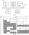
- FIG. 25 For example, a correspondence between the eight modes and the channel is shown in FIG. 25 .
- This embodiment of the present invention provides a method for indicating a channel in a wireless local area network WLAN.
- a sending station generates and sends a physical protocol data unit PPDU, the PPDU includes a preamble field and a data field, a high efficiency signal field HE-SIG-A of the preamble field includes a bandwidth identifier, and the bandwidth identifier is used to indicate a data transmission channel.
- a discontinuous channel in a frequency domain in a wireless local area network is indicated, an available data transmission channel is improved, and a system throughput is increased.
- Embodiment 8 of the present invention provides a method, which is applied to a WLAN, for indicating a channel.
- the method may be applied to a station, for example, the AP and the STA 1 to the STA 3 in FIG. 2 .
- the station may support a next-generation WLAN standard, for example, the 802.11ax standard.
- a data transmission channel is indicated by using a bandwidth identifier in a high efficiency signal field HE-SIG-A of a preamble field in a PPDU, and the bandwidth (BW) identifier includes at least three bits.
- the data transmission channel includes the following eight modes:
- mode 6 includes two implementations.
- the first implementation in mode 6 is a primary 20 MHz channel, a secondary 20 MHz channel, and a channel, whose location is the same parity as that of the primary 20 MHz channel, of a secondary 40 MHz channel.
- the second implementation in mode 6 is a primary 20 MHz channel, a secondary 20 MHz channel, and a channel, whose location is opposite parity comparing with that of the primary 20 MHz channel, of a secondary 40 MHz channel.
- Mode 7 a primary 20 MHz channel, a secondary 20 MHz channel, and a secondary 80 MHz channel.
- Mode 8 a primary 20 MHz channel, a secondary 40 MHz channel, and a secondary 80 MHz channel.
- bandwidth identifier 000 001 010 011 100 101 110 111 Mode Mode 1 Mode 2 Mode 3 Mode 4 Mode 5 Mode 6 Mode 7 Mode 8
- FIG. 26 For example, a correspondence between the eight modes and the channel is shown in FIG. 26 or FIG. 27 .
- This embodiment of the present invention provides a method for indicating a channel in a wireless local area network WLAN.
- a sending station generates and sends a physical protocol data unit PPDU, the PPDU includes a preamble field and a data field, a high efficiency signal field HE-SIG-A of the preamble field includes a bandwidth identifier, and the bandwidth identifier is used to indicate a data transmission channel.
- a discontinuous channel in a frequency domain in a wireless local area network is indicated, an available data transmission channel is improved, and a system throughput is increased.
Landscapes
- Engineering & Computer Science (AREA)
- Signal Processing (AREA)
- Computer Networks & Wireless Communication (AREA)
- Mobile Radio Communication Systems (AREA)
Claims (15)
- Procédé permettant d'indiquer un canal dans un réseau local sans fil, WLAN, ledit procédé étant exécuté par une station d'envoi et comprenant :la génération (101, 201) d'une unité de données de protocole physique, PPDU, la PPDU comportant un champ de préambule et un champ de données, un champ de signal à efficacité élevée, HE-SIG-A, du champ de préambule comportant un identifiant de bande passante et l'identifiant de bande passante indiquant un canal de transmission de données de la PPDU ;l'envoi (102, 202) de la PPDU ;caractérisé en ce que,l'identifiant de bande passante comporte trois bits ; etlorsque l'identifiant de bande passante est une première valeur, la première valeur indique un premier mode du canal de transmission de données dans un canal avec une bande passante de 80 MHz ; dans le premier mode, un canal primaire de 20 MHz et un canal secondaire de 40 MHz sont inclus dans le canal de transmission de données ; etlorsque l'identifiant de bande passante est une deuxième valeur, la deuxième valeur indique un deuxième mode du canal de transmission de données dans un canal avec une bande passante de 80 MHz ; dans le deuxième mode, le canal primaire de 20 MHz, le canal secondaire de 20 MHz et un canal de 20 MHz du canal secondaire de 40 MHz sont inclus dans le canal de transmission de données.
- Procédé selon la revendication 1, dans lequel la première valeur est de 100.
- Procédé selon la revendication 1, dans lequel la deuxième valeur est de 101.
- Procédé permettant d'indiquer un canal dans un réseau local sans fil, WLAN, ledit procédé étant exécuté par une station d'envoi et comprenant :la génération (101, 201) d'une unité de données de protocole physique, PPDU, la PPDU comprenant un champ de préambule et un champ de données, un champ de signal à efficacité élevée, HE-SIG-A, du champ de préambule comportant un identifiant de bande passante, l'identifiant de bande passante indiquant un canal de transmission de données de la PPDU ;l'envoi (102, 202) de la PPDU ;caractérisé en ce que l'identifiant de bande passante comporte trois bits ; etlorsque l'identifiant de bande passante est une troisième valeur, la troisième valeur indique un troisième mode du canal de transmission de données dans un canal avec une bande passante de 160 MHz ; dans le troisième mode, un canal primaire de 20 MHz, et un canal secondaire de 40 MHz, et au moins un canal de 20 MHz d'un canal secondaire de 80 MHz sont inclus dans le canal de transmission de données ; etlorsque l'identifiant de bande passante est une quatrième valeur, la quatrième valeur indique un quatrième mode du canal de transmission de données dans un canal avec une bande passante de 160 MHz ; dans le quatrième mode, le canal primaire de 20 MHz, un canal secondaire de 20 MHz et au moins un canal de 20 MHz du canal secondaire de 80 MHz sont inclus dans le canal de transmission de données.
- Procédé selon l'une quelconque des revendications 1 à 4, dans lequel le canal de transmission de données est discontinue au niveau du domaine fréquentiel.
- Appareil permettant d'indiquer un canal dans un réseau local sans fil, WLAN, comprenant :un circuit de bande de base (1030), configuré pour générer une unité de données de protocole physique, PPDU, la PPDU comprenant un champ de préambule et un champ de données, un champ de signal à efficacité élevée, HE-SIG-A du champ de préambule comportant un identifiant de bande passante, l'identifiant de bande passante indiquant un canal de transmission de données de la PPDU ; etun circuit de radiofréquence (1040), configuré pour envoyer la PPDU ;caractérisé en ce que l'identifiant de bande passante comporte trois bits ;lorsque l'identifiant de bande passante est une première valeur, la première valeur indique un premier mode du canal de transmission de données dans un canal avec une bande passante de 80 MHz ; dans le premier mode, un canal primaire de 20 MHz et un canal secondaire de 40 MHz sont inclus dans le canal de transmission de données ; etlorsque l'identifiant de bande passante est une deuxième valeur, la deuxième valeur indique un deuxième mode du canal de transmission de données dans un canal avec une bande passante de 80 MHz ; dans le deuxième mode, le canal primaire de 20 MHz, un canal secondaire de 20 MHz et un canal de 20 MHz du canal secondaire de 40 MHz sont inclus dans le canal de transmission de données.
- Appareil selon la revendication 6, dans lequel la première valeur est de 100.
- Appareil selon la revendication 6, dans lequel la deuxième valeur est de 101.
- Appareil permettant d'indiquer un canal dans un réseau local sans fil, WLAN, comprenant :un circuit de bande de base (1030), configuré pour générer une unité de données de protocole physique, PPDU, la PPDU comprenant un champ de préambule et un champ de données, un champ de signal à efficacité élevée, HE-SIG-A du champ de préambule comportant un identifiant de bande passante, l'identifiant de bande passante indiquant un canal de transmission de données de la PPDU ; etun circuit de radiofréquence (1040), configuré pour envoyer la PPDU ;caractérisé en ce que l'identifiant de bande passante comporte trois bits ;lorsque l'identifiant de bande passante est une troisième valeur, la troisième valeur indique un troisième mode du canal de transmission de données dans un canal avec une bande passante de 160 MHz ; dans le troisième mode, un canal primaire de 20 MHz, et un canal secondaire de 40 MHz, et au moins un canal de 20 MHz d'un canal secondaire de 80 MHz sont inclus dans le canal de transmission de données ; etlorsque l'identifiant de bande passante est une quatrième valeur, la quatrième valeur indique un quatrième mode du canal de transmission de données dans un canal avec une bande passante de 160 MHz ; dans le quatrième mode, le canal primaire de 20 MHz, un canal secondaire de 20 MHz et au moins un canal de 20 MHz du canal secondaire de 80 MHz sont inclus dans le canal de transmission de données.
- Appareil selon l'une quelconque des revendications 6 à 9, dans lequel le canal de transmission de données est dicontinue au niveau du domaine fréquentiel.
- Appareil dans un réseau local sans fil, WLAN, configuré pour :recevoir une unité de données de protocole physique, PPDU, la PPDU comprenant un champ de préambule et un champ de données, un champ de signal à efficacité élevée, HE-SIG-A, du champ de préambule comprenant un identifiant de bande passante, l'identifiant de bande passante indiquant un canal de transmission de données de la PPDU ; etdéterminer le canal de transmission de données de la PPDU en fonction de l'identifiant de bande passante ;caractérisé en ce que,l'identifiant de bande passante comporte trois bits ; etlorsque l'identifiant de bande passante est une première valeur, la première valeur indique un premier mode du canal de transmission de données dans un canal avec une bande passante de 80 MHz ; dans le premier mode, un canal primaire de 20 MHz et un canal secondaire de 40 MHz sont inclus dans le canal de transmission de données ; etlorsque l'identifiant de bande passante est une deuxième valeur, la deuxième valeur indique un deuxième mode du canal de transmission de données dans un canal avec une bande passante de 80 MHz ; dans le deuxième mode, le canal primaire de 20 MHz, un canal secondaire de 20 MHz et un canal de 20 MHz du canal secondaire de 40 MHz sont inclus dans le canal de transmission de données.
- Appareil selon la revendication 11, dans lequel la première valeur est de 100.
- Appareil selon la revendication 11, dans lequel la deuxième valeur est de 101.
- Appareil dans un réseau local sans fil, WLAN, configuré pour :recevoir une unité de données de protocole physique, PPDU, la PPDU comprenant un champ de préambule et un champ de données, un champ de signal à efficacité élevée, HE-SIG-A, du champ de préambule comprenant un identifiant de bande passante, l'identifiant de bande passante indiquant un canal de transmission de données de la PPDU ;déterminer le canal de transmission de données de la PPDU en fonction de l'identifiant de bande passante ;caractérisé en ce que,lorsque l'identifiant de bande passante est une troisième valeur, la troisième valeur indique un troisième mode du canal de transmission de données dans un canal avec une bande passante de 160 MHz ; dans le troisième mode, un canal primaire de 20 MHz, et un canal secondaire de 40 MHz, et au moins un canal de 20 MHz du canal secondaire de 80 MHz sont inclus dans le canal de transmission de données ;lorsque l'identifiant de bande passante est une quatrième valeur, la quatrième valeur indique un quatrième mode du canal de transmission de données dans un canal avec une bande passante de 160 MHz ; dans le quatrième mode, le canal primaire de 20 MHz, un canal secondaire de 20 MHz et au moins un canal de 20 MHz du canal secondaire de 80 MHz sont inclus dans le canal de transmission de données.
- Support lisible par ordinateur sur lequel un programme est enregistré, caractérisé en ce que le programme, lorsqu'il est exécuté, permet à un ordinateur d'exécuter le procédé de l'une quelconque des revendications 1 à 5.
Priority Applications (1)
| Application Number | Priority Date | Filing Date | Title |
|---|---|---|---|
| EP21207256.5A EP4027564B1 (fr) | 2016-02-06 | 2016-12-21 | Procédé permettant d'indiquer un canal dans un réseau local sans fil |
Applications Claiming Priority (4)
| Application Number | Priority Date | Filing Date | Title |
|---|---|---|---|
| CN201610084191 | 2016-02-06 | ||
| CN201610128055 | 2016-03-07 | ||
| CN201610353330.8A CN107046460B (zh) | 2016-02-06 | 2016-05-24 | 一种无线局域网中信道指示的方法和装置 |
| PCT/CN2016/111325 WO2017133338A1 (fr) | 2016-02-06 | 2016-12-21 | Dispositif et procédé d'indication de canal dans un réseau local sans fil |
Related Child Applications (1)
| Application Number | Title | Priority Date | Filing Date |
|---|---|---|---|
| EP21207256.5A Division EP4027564B1 (fr) | 2016-02-06 | 2016-12-21 | Procédé permettant d'indiquer un canal dans un réseau local sans fil |
Publications (3)
| Publication Number | Publication Date |
|---|---|
| EP3402111A1 EP3402111A1 (fr) | 2018-11-14 |
| EP3402111A4 EP3402111A4 (fr) | 2019-01-16 |
| EP3402111B1 true EP3402111B1 (fr) | 2021-12-08 |
Family
ID=59542703
Family Applications (2)
| Application Number | Title | Priority Date | Filing Date |
|---|---|---|---|
| EP16889144.8A Active EP3402111B1 (fr) | 2016-02-06 | 2016-12-21 | Dispositives et procédés d'indication de canal dans un réseau local sans fil |
| EP21207256.5A Active EP4027564B1 (fr) | 2016-02-06 | 2016-12-21 | Procédé permettant d'indiquer un canal dans un réseau local sans fil |
Family Applications After (1)
| Application Number | Title | Priority Date | Filing Date |
|---|---|---|---|
| EP21207256.5A Active EP4027564B1 (fr) | 2016-02-06 | 2016-12-21 | Procédé permettant d'indiquer un canal dans un réseau local sans fil |
Country Status (13)
| Country | Link |
|---|---|
| US (3) | US10708029B2 (fr) |
| EP (2) | EP3402111B1 (fr) |
| JP (1) | JP6695435B2 (fr) |
| KR (1) | KR102132374B1 (fr) |
| CN (2) | CN112073168B (fr) |
| AU (1) | AU2016391017B2 (fr) |
| CA (1) | CA3014366C (fr) |
| ES (1) | ES2902861T3 (fr) |
| MX (1) | MX383221B (fr) |
| MY (1) | MY198476A (fr) |
| PL (1) | PL4027564T3 (fr) |
| RU (1) | RU2696249C1 (fr) |
| ZA (1) | ZA201805897B (fr) |
Families Citing this family (11)
| Publication number | Priority date | Publication date | Assignee | Title |
|---|---|---|---|---|
| ES2983199T3 (es) | 2015-12-24 | 2024-10-22 | Wilus Inst Standards & Tech Inc | Método de comunicaciones inalámbricas y terminal de comunicaciones inalámbricas, que usan un canal discontinuo |
| CN109687945B (zh) * | 2017-10-19 | 2021-11-30 | 华为技术有限公司 | 帧的传输方法及相关设备 |
| JP7273540B2 (ja) * | 2019-02-28 | 2023-05-15 | キヤノン株式会社 | 通信装置及びその通信方法、情報処理装置及びその制御方法、及び、プログラム |
| CN119341720A (zh) | 2019-05-10 | 2025-01-21 | 交互数字专利控股公司 | 无线发射/接收单元以及由其执行的方法 |
| CN114946250B (zh) * | 2019-11-21 | 2025-06-24 | Lg电子株式会社 | 无线lan系统中通过多个ru接收ppdu的方法及装置 |
| JP7388537B2 (ja) * | 2020-03-04 | 2023-11-29 | 京セラドキュメントソリューションズ株式会社 | 無線通信装置、無線通信設定プログラム及び無線通信設定方法 |
| CN113597000B (zh) * | 2020-04-30 | 2024-06-28 | 华为技术有限公司 | 传输无线局域网分组结构ppdu的方法、相关设备以及系统 |
| CN113747580A (zh) | 2020-05-28 | 2021-12-03 | 华为技术有限公司 | 通信方法及装置 |
| CN116193601B (zh) | 2020-06-19 | 2023-08-22 | 华为技术有限公司 | 一种资源指示方法及接入点和站点 |
| US11606118B2 (en) * | 2020-08-27 | 2023-03-14 | Connectify, Inc. | Data transfer with multiple threshold actions |
| EP4369794A4 (fr) * | 2021-07-06 | 2025-02-12 | Beijing Xiaomi Mobile Software Co., Ltd. | Procédé de communication et dispositif de communication |
Citations (2)
| Publication number | Priority date | Publication date | Assignee | Title |
|---|---|---|---|---|
| WO2016170505A1 (fr) * | 2015-04-23 | 2016-10-27 | Marvell World Trade Ltd. | Opérations de liaison de canal dans des communications sans fil |
| EP3396925A2 (fr) * | 2015-12-24 | 2018-10-31 | Wilus Institute of Standards and Technology Inc. | Procédé de communication sans fil et terminal de communication sans fil qui utilisent un canal discontinu |
Family Cites Families (14)
| Publication number | Priority date | Publication date | Assignee | Title |
|---|---|---|---|---|
| WO2006132467A1 (fr) | 2005-06-09 | 2006-12-14 | Samsung Electronics Co., Ltd. | Procedes et appareils permettant de transmettre et de recevoir des donnees patrimoniales dans un reseau sans fil haut debit |
| EP2095553B1 (fr) * | 2006-11-09 | 2011-04-06 | PGT Photonics S.p.A. | Procédé et dispositif pour un filtrage optique réglable sans à-coup |
| US9794032B2 (en) | 2010-03-05 | 2017-10-17 | Lg Electronics Inc. | PPDU receiving method and apparatus based on the MIMO technique in a WLAN system |
| WO2012035196A1 (fr) | 2010-09-13 | 2012-03-22 | Nokia Corporation | Collaboration en termes de réservation de canal |
| EP2854474B1 (fr) * | 2012-05-23 | 2017-05-10 | Huawei Technologies Co., Ltd. | Procédé de communication dans un réseau local sans fil, et procédé de réception et dispositif correspondants |
| EP2883362A4 (fr) * | 2012-08-13 | 2016-10-05 | Lg Electronics Inc | Procédé de découpage en canaux dans une bande d'espace blanc et appareil associé |
| US9344238B2 (en) * | 2013-04-15 | 2016-05-17 | Qualcomm Incorporated | Systems and methods for backwards-compatible preamble formats for multiple access wireless communication |
| US10211890B2 (en) | 2013-12-14 | 2019-02-19 | Lg Electronics Inc. | Method and device for transferring data from wireless LAN to plurality of STAs |
| US9681335B2 (en) * | 2014-06-19 | 2017-06-13 | Samsung Electronics Co., Ltd. | Methods for bandwidth efficient operations in wireless local area networks |
| US9647816B2 (en) * | 2014-07-16 | 2017-05-09 | Newracom, Inc. | Wireless local area network communications with varying subcarrier spacings |
| US9537702B2 (en) * | 2014-10-23 | 2017-01-03 | Uurmi Systems Private Limited | Method and apparatus for identifying channel bandwidth and channel offset of an orthogonal frequency division multiplexing signal |
| GB2537806B (en) * | 2015-03-05 | 2018-07-11 | Canon Kk | Non-contiguous channel usage in multi-channel wireless networks |
| US10560240B2 (en) * | 2015-12-16 | 2020-02-11 | Lg Electronics Inc. | Method for supporting flexible resource allocation in wireless communication system, and device therefor |
| US10320551B2 (en) * | 2016-06-21 | 2019-06-11 | Marvell World Trade Ltd. | Channel bonding design and signaling in wireless communications |
-
2016
- 2016-05-24 CN CN202010963120.7A patent/CN112073168B/zh active Active
- 2016-05-24 CN CN201610353330.8A patent/CN107046460B/zh active Active
- 2016-12-21 EP EP16889144.8A patent/EP3402111B1/fr active Active
- 2016-12-21 AU AU2016391017A patent/AU2016391017B2/en active Active
- 2016-12-21 MY MYPI2018702753A patent/MY198476A/en unknown
- 2016-12-21 EP EP21207256.5A patent/EP4027564B1/fr active Active
- 2016-12-21 MX MX2018009570A patent/MX383221B/es unknown
- 2016-12-21 ES ES16889144T patent/ES2902861T3/es active Active
- 2016-12-21 PL PL21207256.5T patent/PL4027564T3/pl unknown
- 2016-12-21 KR KR1020187025238A patent/KR102132374B1/ko active Active
- 2016-12-21 CA CA3014366A patent/CA3014366C/fr active Active
- 2016-12-21 RU RU2018131516A patent/RU2696249C1/ru active
- 2016-12-21 JP JP2018540870A patent/JP6695435B2/ja active Active
-
2018
- 2018-08-06 US US16/055,850 patent/US10708029B2/en active Active
- 2018-09-03 ZA ZA2018/05897A patent/ZA201805897B/en unknown
-
2020
- 2020-06-09 US US16/897,002 patent/US11177924B2/en active Active
-
2021
- 2021-10-25 US US17/510,036 patent/US11664945B2/en active Active
Patent Citations (2)
| Publication number | Priority date | Publication date | Assignee | Title |
|---|---|---|---|---|
| WO2016170505A1 (fr) * | 2015-04-23 | 2016-10-27 | Marvell World Trade Ltd. | Opérations de liaison de canal dans des communications sans fil |
| EP3396925A2 (fr) * | 2015-12-24 | 2018-10-31 | Wilus Institute of Standards and Technology Inc. | Procédé de communication sans fil et terminal de communication sans fil qui utilisent un canal discontinu |
Also Published As
| Publication number | Publication date |
|---|---|
| MY198476A (en) | 2023-08-31 |
| EP3402111A1 (fr) | 2018-11-14 |
| PL4027564T3 (pl) | 2024-09-16 |
| AU2016391017A1 (en) | 2018-08-30 |
| EP4027564B1 (fr) | 2024-07-17 |
| CN112073168A (zh) | 2020-12-11 |
| CN107046460A (zh) | 2017-08-15 |
| ZA201805897B (en) | 2019-08-28 |
| US10708029B2 (en) | 2020-07-07 |
| US11664945B2 (en) | 2023-05-30 |
| CN107046460B (zh) | 2020-09-25 |
| CA3014366A1 (fr) | 2017-08-10 |
| EP4027564A1 (fr) | 2022-07-13 |
| EP3402111A4 (fr) | 2019-01-16 |
| US20180351721A1 (en) | 2018-12-06 |
| CN112073168B (zh) | 2025-07-25 |
| BR112018016013A2 (pt) | 2018-12-18 |
| US20220045825A1 (en) | 2022-02-10 |
| MX383221B (es) | 2025-03-13 |
| US11177924B2 (en) | 2021-11-16 |
| US20200304268A1 (en) | 2020-09-24 |
| AU2016391017B2 (en) | 2019-10-03 |
| KR102132374B1 (ko) | 2020-07-09 |
| JP2019510400A (ja) | 2019-04-11 |
| ES2902861T3 (es) | 2022-03-30 |
| RU2696249C1 (ru) | 2019-08-01 |
| KR20180109994A (ko) | 2018-10-08 |
| CA3014366C (fr) | 2021-12-07 |
| JP6695435B2 (ja) | 2020-05-20 |
Similar Documents
| Publication | Publication Date | Title |
|---|---|---|
| EP4027564B1 (fr) | Procédé permettant d'indiquer un canal dans un réseau local sans fil | |
| US11743945B1 (en) | Methods and devices for communicating in a wireless network with multiple virtual access points | |
| CN116388943B (zh) | 资源单元指示方法、装置及存储介质 | |
| EP4171142B1 (fr) | Procédé de transmission d'unité ppdu et dispositif associé | |
| US11178659B2 (en) | WLAN system resource indication method and apparatus | |
| CN103155446B (zh) | 在无线通信系统中收发信道发射功率信息的方法和装置 | |
| KR20180030457A (ko) | 무선랜 시스템에서 제어 필드를 포함하는 제어 신호를 구성하는 방법 및 장치 | |
| EP4080966B1 (fr) | Procédé d'indication de combinaison d'unités de ressource et appareil de communication | |
| WO2016021941A1 (fr) | Procédé et dispositif d'attribution de ressources sans fil pour envoyer ou recevoir des données dans un réseau local sans fil | |
| WO2016024758A1 (fr) | Procédé et appareil d'affectation de ressource sans fil afin d'empêcher des interférences dans un lan sans fil | |
| US11916624B2 (en) | System and method for enabling multi-user multiple-input-multiple-output communication in wireless networks | |
| CN111030793B (zh) | 一种无线局域网中触发帧传输的方法和装置 | |
| EP4683258A2 (fr) | Procédé de transmission d'informations, appareil de communication, support d'informations lisible par ordinateur et puce | |
| US10979973B2 (en) | Power control method and apparatus | |
| HK40119692A (en) | Resource unit combination indication method and communications apparatus | |
| WO2017133338A1 (fr) | Dispositif et procédé d'indication de canal dans un réseau local sans fil | |
| BR112018016013B1 (pt) | Método e aparelho para indicar um canal em uma rede de área local sem fio (wlan) |
Legal Events
| Date | Code | Title | Description |
|---|---|---|---|
| STAA | Information on the status of an ep patent application or granted ep patent |
Free format text: STATUS: THE INTERNATIONAL PUBLICATION HAS BEEN MADE |
|
| PUAI | Public reference made under article 153(3) epc to a published international application that has entered the european phase |
Free format text: ORIGINAL CODE: 0009012 |
|
| STAA | Information on the status of an ep patent application or granted ep patent |
Free format text: STATUS: REQUEST FOR EXAMINATION WAS MADE |
|
| 17P | Request for examination filed |
Effective date: 20180802 |
|
| AK | Designated contracting states |
Kind code of ref document: A1 Designated state(s): AL AT BE BG CH CY CZ DE DK EE ES FI FR GB GR HR HU IE IS IT LI LT LU LV MC MK MT NL NO PL PT RO RS SE SI SK SM TR |
|
| AX | Request for extension of the european patent |
Extension state: BA ME |
|
| A4 | Supplementary search report drawn up and despatched |
Effective date: 20181219 |
|
| RIC1 | Information provided on ipc code assigned before grant |
Ipc: H04W 74/00 20090101ALI20181213BHEP Ipc: H04W 72/04 20090101ALI20181213BHEP Ipc: H04W 84/12 20090101ALI20181213BHEP Ipc: H04B 7/0452 20170101ALI20181213BHEP Ipc: H04W 24/02 20090101ALI20181213BHEP Ipc: H04L 27/26 20060101ALI20181213BHEP Ipc: H04L 5/00 20060101AFI20181213BHEP |
|
| DAV | Request for validation of the european patent (deleted) | ||
| DAX | Request for extension of the european patent (deleted) | ||
| STAA | Information on the status of an ep patent application or granted ep patent |
Free format text: STATUS: EXAMINATION IS IN PROGRESS |
|
| 17Q | First examination report despatched |
Effective date: 20200320 |
|
| GRAP | Despatch of communication of intention to grant a patent |
Free format text: ORIGINAL CODE: EPIDOSNIGR1 |
|
| STAA | Information on the status of an ep patent application or granted ep patent |
Free format text: STATUS: GRANT OF PATENT IS INTENDED |
|
| RIC1 | Information provided on ipc code assigned before grant |
Ipc: H04L 5/00 20060101AFI20210622BHEP Ipc: H04B 7/0452 20170101ALI20210622BHEP Ipc: H04L 27/26 20060101ALI20210622BHEP Ipc: H04W 72/04 20090101ALI20210622BHEP Ipc: H04W 74/00 20090101ALI20210622BHEP Ipc: H04W 84/12 20090101ALI20210622BHEP Ipc: H04W 24/02 20090101ALI20210622BHEP Ipc: H04W 48/12 20090101ALN20210622BHEP |
|
| RIC1 | Information provided on ipc code assigned before grant |
Ipc: H04L 5/00 20060101AFI20210630BHEP Ipc: H04B 7/0452 20170101ALI20210630BHEP Ipc: H04L 27/26 20060101ALI20210630BHEP Ipc: H04W 72/04 20090101ALI20210630BHEP Ipc: H04W 74/00 20090101ALI20210630BHEP Ipc: H04W 84/12 20090101ALI20210630BHEP Ipc: H04W 24/02 20090101ALI20210630BHEP Ipc: H04W 48/12 20090101ALN20210630BHEP |
|
| INTG | Intention to grant announced |
Effective date: 20210712 |
|
| GRAS | Grant fee paid |
Free format text: ORIGINAL CODE: EPIDOSNIGR3 |
|
| GRAA | (expected) grant |
Free format text: ORIGINAL CODE: 0009210 |
|
| STAA | Information on the status of an ep patent application or granted ep patent |
Free format text: STATUS: THE PATENT HAS BEEN GRANTED |
|
| AK | Designated contracting states |
Kind code of ref document: B1 Designated state(s): AL AT BE BG CH CY CZ DE DK EE ES FI FR GB GR HR HU IE IS IT LI LT LU LV MC MK MT NL NO PL PT RO RS SE SI SK SM TR |
|
| REG | Reference to a national code |
Ref country code: GB Ref legal event code: FG4D |
|
| REG | Reference to a national code |
Ref country code: AT Ref legal event code: REF Ref document number: 1454562 Country of ref document: AT Kind code of ref document: T Effective date: 20211215 Ref country code: CH Ref legal event code: EP |
|
| REG | Reference to a national code |
Ref country code: DE Ref legal event code: R096 Ref document number: 602016067256 Country of ref document: DE |
|
| REG | Reference to a national code |
Ref country code: IE Ref legal event code: FG4D |
|
| REG | Reference to a national code |
Ref country code: ES Ref legal event code: FG2A Ref document number: 2902861 Country of ref document: ES Kind code of ref document: T3 Effective date: 20220330 |
|
| REG | Reference to a national code |
Ref country code: LT Ref legal event code: MG9D |
|
| REG | Reference to a national code |
Ref country code: NL Ref legal event code: MP Effective date: 20211208 |
|
| PG25 | Lapsed in a contracting state [announced via postgrant information from national office to epo] |
Ref country code: RS Free format text: LAPSE BECAUSE OF FAILURE TO SUBMIT A TRANSLATION OF THE DESCRIPTION OR TO PAY THE FEE WITHIN THE PRESCRIBED TIME-LIMIT Effective date: 20211208 Ref country code: LT Free format text: LAPSE BECAUSE OF FAILURE TO SUBMIT A TRANSLATION OF THE DESCRIPTION OR TO PAY THE FEE WITHIN THE PRESCRIBED TIME-LIMIT Effective date: 20211208 Ref country code: FI Free format text: LAPSE BECAUSE OF FAILURE TO SUBMIT A TRANSLATION OF THE DESCRIPTION OR TO PAY THE FEE WITHIN THE PRESCRIBED TIME-LIMIT Effective date: 20211208 Ref country code: BG Free format text: LAPSE BECAUSE OF FAILURE TO SUBMIT A TRANSLATION OF THE DESCRIPTION OR TO PAY THE FEE WITHIN THE PRESCRIBED TIME-LIMIT Effective date: 20220308 |
|
| REG | Reference to a national code |
Ref country code: AT Ref legal event code: MK05 Ref document number: 1454562 Country of ref document: AT Kind code of ref document: T Effective date: 20211208 |
|
| PG25 | Lapsed in a contracting state [announced via postgrant information from national office to epo] |
Ref country code: SE Free format text: LAPSE BECAUSE OF FAILURE TO SUBMIT A TRANSLATION OF THE DESCRIPTION OR TO PAY THE FEE WITHIN THE PRESCRIBED TIME-LIMIT Effective date: 20211208 Ref country code: NO Free format text: LAPSE BECAUSE OF FAILURE TO SUBMIT A TRANSLATION OF THE DESCRIPTION OR TO PAY THE FEE WITHIN THE PRESCRIBED TIME-LIMIT Effective date: 20220308 Ref country code: LV Free format text: LAPSE BECAUSE OF FAILURE TO SUBMIT A TRANSLATION OF THE DESCRIPTION OR TO PAY THE FEE WITHIN THE PRESCRIBED TIME-LIMIT Effective date: 20211208 Ref country code: HR Free format text: LAPSE BECAUSE OF FAILURE TO SUBMIT A TRANSLATION OF THE DESCRIPTION OR TO PAY THE FEE WITHIN THE PRESCRIBED TIME-LIMIT Effective date: 20211208 Ref country code: GR Free format text: LAPSE BECAUSE OF FAILURE TO SUBMIT A TRANSLATION OF THE DESCRIPTION OR TO PAY THE FEE WITHIN THE PRESCRIBED TIME-LIMIT Effective date: 20220309 |
|
| PG25 | Lapsed in a contracting state [announced via postgrant information from national office to epo] |
Ref country code: NL Free format text: LAPSE BECAUSE OF FAILURE TO SUBMIT A TRANSLATION OF THE DESCRIPTION OR TO PAY THE FEE WITHIN THE PRESCRIBED TIME-LIMIT Effective date: 20211208 |
|
| PG25 | Lapsed in a contracting state [announced via postgrant information from national office to epo] |
Ref country code: SM Free format text: LAPSE BECAUSE OF FAILURE TO SUBMIT A TRANSLATION OF THE DESCRIPTION OR TO PAY THE FEE WITHIN THE PRESCRIBED TIME-LIMIT Effective date: 20211208 Ref country code: SK Free format text: LAPSE BECAUSE OF FAILURE TO SUBMIT A TRANSLATION OF THE DESCRIPTION OR TO PAY THE FEE WITHIN THE PRESCRIBED TIME-LIMIT Effective date: 20211208 Ref country code: RO Free format text: LAPSE BECAUSE OF FAILURE TO SUBMIT A TRANSLATION OF THE DESCRIPTION OR TO PAY THE FEE WITHIN THE PRESCRIBED TIME-LIMIT Effective date: 20211208 Ref country code: PT Free format text: LAPSE BECAUSE OF FAILURE TO SUBMIT A TRANSLATION OF THE DESCRIPTION OR TO PAY THE FEE WITHIN THE PRESCRIBED TIME-LIMIT Effective date: 20220408 Ref country code: EE Free format text: LAPSE BECAUSE OF FAILURE TO SUBMIT A TRANSLATION OF THE DESCRIPTION OR TO PAY THE FEE WITHIN THE PRESCRIBED TIME-LIMIT Effective date: 20211208 Ref country code: CZ Free format text: LAPSE BECAUSE OF FAILURE TO SUBMIT A TRANSLATION OF THE DESCRIPTION OR TO PAY THE FEE WITHIN THE PRESCRIBED TIME-LIMIT Effective date: 20211208 |
|
| REG | Reference to a national code |
Ref country code: CH Ref legal event code: PL |
|
| PG25 | Lapsed in a contracting state [announced via postgrant information from national office to epo] |
Ref country code: PL Free format text: LAPSE BECAUSE OF FAILURE TO SUBMIT A TRANSLATION OF THE DESCRIPTION OR TO PAY THE FEE WITHIN THE PRESCRIBED TIME-LIMIT Effective date: 20211208 Ref country code: AT Free format text: LAPSE BECAUSE OF FAILURE TO SUBMIT A TRANSLATION OF THE DESCRIPTION OR TO PAY THE FEE WITHIN THE PRESCRIBED TIME-LIMIT Effective date: 20211208 |
|
| REG | Reference to a national code |
Ref country code: DE Ref legal event code: R097 Ref document number: 602016067256 Country of ref document: DE |
|
| REG | Reference to a national code |
Ref country code: BE Ref legal event code: MM Effective date: 20211231 |
|
| PG25 | Lapsed in a contracting state [announced via postgrant information from national office to epo] |
Ref country code: MC Free format text: LAPSE BECAUSE OF FAILURE TO SUBMIT A TRANSLATION OF THE DESCRIPTION OR TO PAY THE FEE WITHIN THE PRESCRIBED TIME-LIMIT Effective date: 20211208 Ref country code: IS Free format text: LAPSE BECAUSE OF FAILURE TO SUBMIT A TRANSLATION OF THE DESCRIPTION OR TO PAY THE FEE WITHIN THE PRESCRIBED TIME-LIMIT Effective date: 20220408 |
|
| PLBE | No opposition filed within time limit |
Free format text: ORIGINAL CODE: 0009261 |
|
| STAA | Information on the status of an ep patent application or granted ep patent |
Free format text: STATUS: NO OPPOSITION FILED WITHIN TIME LIMIT |
|
| PG25 | Lapsed in a contracting state [announced via postgrant information from national office to epo] |
Ref country code: LU Free format text: LAPSE BECAUSE OF NON-PAYMENT OF DUE FEES Effective date: 20211221 Ref country code: DK Free format text: LAPSE BECAUSE OF FAILURE TO SUBMIT A TRANSLATION OF THE DESCRIPTION OR TO PAY THE FEE WITHIN THE PRESCRIBED TIME-LIMIT Effective date: 20211208 Ref country code: AL Free format text: LAPSE BECAUSE OF FAILURE TO SUBMIT A TRANSLATION OF THE DESCRIPTION OR TO PAY THE FEE WITHIN THE PRESCRIBED TIME-LIMIT Effective date: 20211208 |
|
| 26N | No opposition filed |
Effective date: 20220909 |
|
| PG25 | Lapsed in a contracting state [announced via postgrant information from national office to epo] |
Ref country code: SI Free format text: LAPSE BECAUSE OF FAILURE TO SUBMIT A TRANSLATION OF THE DESCRIPTION OR TO PAY THE FEE WITHIN THE PRESCRIBED TIME-LIMIT Effective date: 20211208 Ref country code: BE Free format text: LAPSE BECAUSE OF NON-PAYMENT OF DUE FEES Effective date: 20211231 |
|
| PG25 | Lapsed in a contracting state [announced via postgrant information from national office to epo] |
Ref country code: LI Free format text: LAPSE BECAUSE OF NON-PAYMENT OF DUE FEES Effective date: 20211231 Ref country code: CH Free format text: LAPSE BECAUSE OF NON-PAYMENT OF DUE FEES Effective date: 20211231 |
|
| PG25 | Lapsed in a contracting state [announced via postgrant information from national office to epo] |
Ref country code: IT Free format text: LAPSE BECAUSE OF FAILURE TO SUBMIT A TRANSLATION OF THE DESCRIPTION OR TO PAY THE FEE WITHIN THE PRESCRIBED TIME-LIMIT Effective date: 20211208 |
|
| P01 | Opt-out of the competence of the unified patent court (upc) registered |
Effective date: 20230514 |
|
| PG25 | Lapsed in a contracting state [announced via postgrant information from national office to epo] |
Ref country code: CY Free format text: LAPSE BECAUSE OF FAILURE TO SUBMIT A TRANSLATION OF THE DESCRIPTION OR TO PAY THE FEE WITHIN THE PRESCRIBED TIME-LIMIT Effective date: 20211208 |
|
| PG25 | Lapsed in a contracting state [announced via postgrant information from national office to epo] |
Ref country code: HU Free format text: LAPSE BECAUSE OF FAILURE TO SUBMIT A TRANSLATION OF THE DESCRIPTION OR TO PAY THE FEE WITHIN THE PRESCRIBED TIME-LIMIT; INVALID AB INITIO Effective date: 20161221 |
|
| PG25 | Lapsed in a contracting state [announced via postgrant information from national office to epo] |
Ref country code: MK Free format text: LAPSE BECAUSE OF FAILURE TO SUBMIT A TRANSLATION OF THE DESCRIPTION OR TO PAY THE FEE WITHIN THE PRESCRIBED TIME-LIMIT Effective date: 20211208 |
|
| PG25 | Lapsed in a contracting state [announced via postgrant information from national office to epo] |
Ref country code: TR Free format text: LAPSE BECAUSE OF FAILURE TO SUBMIT A TRANSLATION OF THE DESCRIPTION OR TO PAY THE FEE WITHIN THE PRESCRIBED TIME-LIMIT Effective date: 20211208 |
|
| PG25 | Lapsed in a contracting state [announced via postgrant information from national office to epo] |
Ref country code: MT Free format text: LAPSE BECAUSE OF FAILURE TO SUBMIT A TRANSLATION OF THE DESCRIPTION OR TO PAY THE FEE WITHIN THE PRESCRIBED TIME-LIMIT Effective date: 20211208 |
|
| PGFP | Annual fee paid to national office [announced via postgrant information from national office to epo] |
Ref country code: DE Payment date: 20251104 Year of fee payment: 10 |
|
| PGFP | Annual fee paid to national office [announced via postgrant information from national office to epo] |
Ref country code: GB Payment date: 20251030 Year of fee payment: 10 |
|
| PGFP | Annual fee paid to national office [announced via postgrant information from national office to epo] |
Ref country code: FR Payment date: 20251110 Year of fee payment: 10 |
|
| PGFP | Annual fee paid to national office [announced via postgrant information from national office to epo] |
Ref country code: IE Payment date: 20251111 Year of fee payment: 10 |
|
| PGFP | Annual fee paid to national office [announced via postgrant information from national office to epo] |
Ref country code: ES Payment date: 20260113 Year of fee payment: 10 |