EP3402124B1 - Dienstausstellungsverfahren und -vorrichtung - Google Patents
Dienstausstellungsverfahren und -vorrichtung Download PDFInfo
- Publication number
- EP3402124B1 EP3402124B1 EP17842597.1A EP17842597A EP3402124B1 EP 3402124 B1 EP3402124 B1 EP 3402124B1 EP 17842597 A EP17842597 A EP 17842597A EP 3402124 B1 EP3402124 B1 EP 3402124B1
- Authority
- EP
- European Patent Office
- Prior art keywords
- service
- domain
- routing
- template
- policy
- Prior art date
- Legal status (The legal status is an assumption and is not a legal conclusion. Google has not performed a legal analysis and makes no representation as to the accuracy of the status listed.)
- Active
Links
Images




Classifications
-
- H—ELECTRICITY
- H04—ELECTRIC COMMUNICATION TECHNIQUE
- H04L—TRANSMISSION OF DIGITAL INFORMATION, e.g. TELEGRAPHIC COMMUNICATION
- H04L41/00—Arrangements for maintenance, administration or management of data switching networks, e.g. of packet switching networks
- H04L41/08—Configuration management of networks or network elements
- H04L41/0803—Configuration setting
- H04L41/084—Configuration by using pre-existing information, e.g. using templates or copying from other elements
- H04L41/0843—Configuration by using pre-existing information, e.g. using templates or copying from other elements based on generic templates
-
- H—ELECTRICITY
- H04—ELECTRIC COMMUNICATION TECHNIQUE
- H04L—TRANSMISSION OF DIGITAL INFORMATION, e.g. TELEGRAPHIC COMMUNICATION
- H04L41/00—Arrangements for maintenance, administration or management of data switching networks, e.g. of packet switching networks
- H04L41/04—Network management architectures or arrangements
- H04L41/044—Network management architectures or arrangements comprising hierarchical management structures
-
- H—ELECTRICITY
- H04—ELECTRIC COMMUNICATION TECHNIQUE
- H04L—TRANSMISSION OF DIGITAL INFORMATION, e.g. TELEGRAPHIC COMMUNICATION
- H04L12/00—Data switching networks
- H04L12/28—Data switching networks characterised by path configuration, e.g. LAN [Local Area Networks] or WAN [Wide Area Networks]
- H04L12/2854—Wide area networks, e.g. public data networks
-
- H—ELECTRICITY
- H04—ELECTRIC COMMUNICATION TECHNIQUE
- H04L—TRANSMISSION OF DIGITAL INFORMATION, e.g. TELEGRAPHIC COMMUNICATION
- H04L12/00—Data switching networks
- H04L12/28—Data switching networks characterised by path configuration, e.g. LAN [Local Area Networks] or WAN [Wide Area Networks]
- H04L12/46—Interconnection of networks
- H04L12/4641—Virtual LANs, VLANs, e.g. virtual private networks [VPN]
-
- H—ELECTRICITY
- H04—ELECTRIC COMMUNICATION TECHNIQUE
- H04L—TRANSMISSION OF DIGITAL INFORMATION, e.g. TELEGRAPHIC COMMUNICATION
- H04L41/00—Arrangements for maintenance, administration or management of data switching networks, e.g. of packet switching networks
- H04L41/08—Configuration management of networks or network elements
- H04L41/0893—Assignment of logical groups to network elements
-
- H—ELECTRICITY
- H04—ELECTRIC COMMUNICATION TECHNIQUE
- H04L—TRANSMISSION OF DIGITAL INFORMATION, e.g. TELEGRAPHIC COMMUNICATION
- H04L41/00—Arrangements for maintenance, administration or management of data switching networks, e.g. of packet switching networks
- H04L41/08—Configuration management of networks or network elements
- H04L41/0894—Policy-based network configuration management
-
- H—ELECTRICITY
- H04—ELECTRIC COMMUNICATION TECHNIQUE
- H04L—TRANSMISSION OF DIGITAL INFORMATION, e.g. TELEGRAPHIC COMMUNICATION
- H04L41/00—Arrangements for maintenance, administration or management of data switching networks, e.g. of packet switching networks
- H04L41/08—Configuration management of networks or network elements
- H04L41/0895—Configuration of virtualised networks or elements, e.g. virtualised network function or OpenFlow elements
-
- H—ELECTRICITY
- H04—ELECTRIC COMMUNICATION TECHNIQUE
- H04L—TRANSMISSION OF DIGITAL INFORMATION, e.g. TELEGRAPHIC COMMUNICATION
- H04L41/00—Arrangements for maintenance, administration or management of data switching networks, e.g. of packet switching networks
- H04L41/40—Arrangements for maintenance, administration or management of data switching networks, e.g. of packet switching networks using virtualisation of network functions or resources, e.g. SDN or NFV entities
-
- H—ELECTRICITY
- H04—ELECTRIC COMMUNICATION TECHNIQUE
- H04L—TRANSMISSION OF DIGITAL INFORMATION, e.g. TELEGRAPHIC COMMUNICATION
- H04L41/00—Arrangements for maintenance, administration or management of data switching networks, e.g. of packet switching networks
- H04L41/50—Network service management, e.g. ensuring proper service fulfilment according to agreements
- H04L41/5003—Managing SLA; Interaction between SLA and QoS
-
- H—ELECTRICITY
- H04—ELECTRIC COMMUNICATION TECHNIQUE
- H04L—TRANSMISSION OF DIGITAL INFORMATION, e.g. TELEGRAPHIC COMMUNICATION
- H04L41/00—Arrangements for maintenance, administration or management of data switching networks, e.g. of packet switching networks
- H04L41/50—Network service management, e.g. ensuring proper service fulfilment according to agreements
- H04L41/5041—Network service management, e.g. ensuring proper service fulfilment according to agreements characterised by the time relationship between creation and deployment of a service
- H04L41/5048—Automatic or semi-automatic definitions, e.g. definition templates
-
- H—ELECTRICITY
- H04—ELECTRIC COMMUNICATION TECHNIQUE
- H04L—TRANSMISSION OF DIGITAL INFORMATION, e.g. TELEGRAPHIC COMMUNICATION
- H04L41/00—Arrangements for maintenance, administration or management of data switching networks, e.g. of packet switching networks
- H04L41/50—Network service management, e.g. ensuring proper service fulfilment according to agreements
- H04L41/5041—Network service management, e.g. ensuring proper service fulfilment according to agreements characterised by the time relationship between creation and deployment of a service
- H04L41/5054—Automatic deployment of services triggered by the service manager, e.g. service implementation by automatic configuration of network components
-
- H—ELECTRICITY
- H04—ELECTRIC COMMUNICATION TECHNIQUE
- H04L—TRANSMISSION OF DIGITAL INFORMATION, e.g. TELEGRAPHIC COMMUNICATION
- H04L45/00—Routing or path finding of packets in data switching networks
- H04L45/02—Topology update or discovery
- H04L45/04—Interdomain routing, e.g. hierarchical routing
-
- H—ELECTRICITY
- H04—ELECTRIC COMMUNICATION TECHNIQUE
- H04L—TRANSMISSION OF DIGITAL INFORMATION, e.g. TELEGRAPHIC COMMUNICATION
- H04L45/00—Routing or path finding of packets in data switching networks
- H04L45/38—Flow based routing
-
- H—ELECTRICITY
- H04—ELECTRIC COMMUNICATION TECHNIQUE
- H04L—TRANSMISSION OF DIGITAL INFORMATION, e.g. TELEGRAPHIC COMMUNICATION
- H04L45/00—Routing or path finding of packets in data switching networks
- H04L45/64—Routing or path finding of packets in data switching networks using an overlay routing layer
-
- H—ELECTRICITY
- H04—ELECTRIC COMMUNICATION TECHNIQUE
- H04L—TRANSMISSION OF DIGITAL INFORMATION, e.g. TELEGRAPHIC COMMUNICATION
- H04L41/00—Arrangements for maintenance, administration or management of data switching networks, e.g. of packet switching networks
- H04L41/50—Network service management, e.g. ensuring proper service fulfilment according to agreements
- H04L41/5077—Network service management, e.g. ensuring proper service fulfilment according to agreements wherein the managed service relates to simple transport services, i.e. providing only network infrastructure
Definitions
- This application relates to the field of service orchestration, and in particular, to a service provisioning method and apparatus.
- Software-defined networking (English: Software Defined Networking, SDN for short) is a new network technology that springs up in recent years.
- a main feature of the SDN is that a control permission of a network device can be separated and managed by a centralized controller, control is performed independent of the network device itself, and a difference between network devices is shielded, so that centralized management can be performed on different network devices.
- the SDN service orchestration solution is not applicable to service orchestration of all scenarios such as a wide area network (English: Wide Area Network, WAN for short) side service.
- a service attribute such as a topology type, or a service type
- a service policy such as an address pool policy or a routing policy used to configure the service, of the WAN side service needs to be designed. Because the service policy is not a parameter, when service orchestration is performed, the service policy cannot be used as a parameter to be orchestrated, and cannot be directly used during subsequent service provisioning. Consequently, the WAN side service cannot be orchestrated by using the existing SDN solution.
- US 2016/057234 A1 discloses concepts and technologies that are directed to a service compiler component and service controller for Open Systems Interconnection ("OSI") communication model layer 4 through layer 7 services in a cloud computing system.
- the service compiler component can receive compiler data associated with a new service.
- the service compiler component also can analyze the compiler data at least to determine at least one virtual network function ("VNF") to be used to instantiate the new service.
- VNF virtual network function
- the service compiler also can generate a template for the new service.
- US 2015/180736 A1 discloses technologies for generating service templates to achieve service level agreement (SLA) metrics.
- SLA service level agreement
- the generic service template defines a virtual application service to be provided by a datacenter.
- the service template generator generates one or more specific service templates based on the generic service template.
- Each of the specific service templates provides one or more of the specified SLA metrics, such as specified uptime, reliability, or manageability.
- the generated service templates are stored in a service template catalog.
- a datacenter manager controlling a number of datacenter nodes receives a service request including one or more SLA requirements, selects a matching service template from the service template catalog, and deploys the selected service template.
- the service template generator and the datacenter manager may be the same device. Other embodiments and claimed.
- EP 3 051 458 A1 discloses a dynamic licensing method, implemented in an integrated system, that includes, responsive to an end user requesting a third-party application through the integrated system; determining a license key, for the third-party application, in the integrated system using a public key associated with the integrated system; receiving an encrypted validation result from a system associated with the third-party application that validates the license key using a private key and software provided with the integrated system, wherein the system returns the encrypted validation results to the third-party application which provides the encrypted validation results to the integrated system; and decrypting the encrypted validation results using previously allocated session key and determining whether to run the third-party application based on the validation results.
- WO 02/06973 A1 discloses: In a system of data, voice, application and video services that depend on multiple, interconnected network technologies, a management system suited for a particular networking technology manages each separate technology domain.
- a higher-level cross-domain system performs the task of automated service provisioning including (i) interacting with the services providers and consumers to determine the services being contracted for; (ii) collecting data from the multiple management systems; and (iii) sending instruction to the multiple management systems in order to provision the required service and the associated quality across the multiple networking technologies.
- the individual management systems of the disclosure collect service data from their respective technology domains and provide it to a service collection function. This data is then utilized by the service determination function to determine what service instruction should be sent from a service instruction function to the management systems for implementation in their respective technology domains.
- a mechanism is disclosed for automatic processing of these formal policy definitions in a TOSCA runtime environment that was developed based on the proposed architecture of the TOSCA primer.
- prototypical implementations of security policies for encrypting databases and for limiting the geographical location of the Cloud servers are presented. How the runtime environment is ensuring these policies is demonstrated and it is shown how they affect the deployment of the application.
- embodiments of the present invention provide a service provisioning method according to claim 1 and a service provisioning apparatus according to claim 6.
- Advantageous features are set out in the appended dependent claims.
- FIG. 1 shows an application architecture according to an embodiment of the present invention.
- the application architecture mainly includes multiple operator networks (domains for short below) 10 and multiple user networks 20.
- the user network 20 includes a customer edge (English: Customer Edge, CE for short) device 21.
- the CE device 21 may be a router or a switch, or may be a host.
- the domain 10 includes a provider edge (English: Provider Edge, PE for short) device 11 and a provider (English: Provider, P for short) device 12.
- the PE device 11 may be an edge router on the operator network, and is directly connected to the CE device 21 on the user network.
- the P device 12 may be a P router on the operator network, and is not directly connected to the CE device 21.
- an entire network may be divided into an orchestrator 100, a controller 200, and a router 300 by layer.
- the router 300 includes the PE device 11 and the P device 12 in the domain 10.
- a controller 200 is disposed in each domain 10, and multiple controllers 200 are controlled by one orchestrator 100.
- the entire application architecture may be further divided into a service model layer, a network model layer, and a network element model layer.
- the orchestrator 100 manages another device by using the service model layer.
- the controller 200 manages the another device by using the network model layer.
- the router 300 describes a function of the router 300 by using the network element model layer.
- the foregoing application architecture may be software-defined networking (SDN).
- SDN software-defined networking
- an orchestrator an orchestrator
- OpenStack is a representative of cloud management tools.
- the OpenStack provides a network virtualization service by using a network component Neutron (which is originally Quantum), allows a tenant to create and manage a virtualized network, and provides a standardized plugin architecture, to facilitate a connection to the orchestrator.
- the OpenStack mainly includes nine modules.
- a Heat module creates a template for resource objects that a user needs to manage, and identifies, from the objects, some attributes that need to be entered by the user and some attributes always need to be filled in according to a service scenario.
- a parameter that always needs to be filled in is filled in by using a template.
- a parameter entered by the user is set by a parameter (Parameters), and is entered by the user when a resource object is created according to the service scenario.
- the Heat module currently uses a "(template+parameter)-based" manner. The manner based on template+parameter is limited to only a range of resource objects managed by the user, and cannot support a dynamic parameter that needs to be based on a policy and that is not in a resource (Resource) object attribute.
- Service orchestration of a WAN network is usually related to dynamic parameters on a network side. These parameters are dynamically generated and cannot be entered by a customer. Difficulties in the WAN side service orchestration are described with reference to FIG. 1 and by using a virtual private network (English: Virtual Private Network, VPN for short) as an example. Domains A and B are two operator networks. An interface gateway is on the domain B network, and all enterprise VPN services need to pass through the domain B. In the VPN service, an Option A mode is used as an inter-domain interconnection mode. In consideration of planning, the VPN has the following features:
- the foregoing tunnel policy, a VPN type, and the like cannot be entered by a user.
- These parameters do not belong to attributes of the VPN, and therefore cannot be included in an L3VPN template either.
- a combination manner of these parameters depends on a service dynamic route result. Consequently, the template+parameter manner cannot resolve a service orchestration problem of the foregoing VPN service.
- This application provides a new service orchestration and provisioning method.
- a service attribute, a service policy, and a service parameter are all used as options of a service template, and when service provisioning is performed, a service configuration is performed according to the service attribute, the service policy, and the service parameter in the service template.
- FIG. 2 is a schematic diagram of a possible hardware structure of the orchestrator 100 shown in FIG. 1 .
- the orchestrator may include: a processor 10 that includes one or more processing cores, a memory 20 that includes one or more computer-readable storage media, and a communications interface 30.
- a person skilled in the art may understand that, the orchestrator is not limited to the structure shown in FIG. 2 and may include: more or fewer components than those shown in the figure, or a combination of some components, or components disposed differently.
- the processor 10 is a control center of the orchestrator, and is connected to various parts of the entire orchestrator by using various interfaces and lines. By running or executing a software program and/or a module stored in the memory 20, and invoking data stored in the memory 20, the processor 10 performs various functions and data processing of the orchestrator, thereby performing overall control on the orchestrator.
- the processor 10 may be implemented by using a CPU, or may be implemented by using a network processor (English: network processor, NP for short) that has a function of a control plane.
- the memory 20 may be configured to store various data such as various configuration parameters, and a software program and/or an application program module.
- the software program and/or the application program module may be executed by the processor 10.
- the memory 20 may mainly include a program storage area and a data storage area.
- the program storage area may store an operating system 21 and at least one application program module 22 that has the function, such as a first obtaining module, or a publish module.
- the data storage area may store data created according to use of the orchestrator 100, such as a service template.
- the memory 20 may include a high-speed random access memory, and may further include a non-volatile memory, such as at least one magnetic disk storage device, a flash memory, or another volatile solid-state storage device.
- the memory 20 may further include a memory controller, so that the processor 10 can access the memory 20.
- the application program module 22 includes at least: a first obtaining module 221 adapted to obtain a service template, a second obtaining module 222 adapted to obtain parameters entered by an operator, a write module 223 adapted to fill in the service template, an association module 224 adapted to perform association, and a publish module 225 adapted to publish the service template.
- the first obtaining module 221 is adapted to obtain a service template, where the service template includes the following options: a service attribute used to describe a service, a service policy used to configure the service, and a service parameter that can be filled in by a user.
- the second obtaining module 222 is adapted to obtain a service identity, a service attribute, and a service policy that are entered by an operator and a default service parameter.
- the write module 223 is adapted to fill in the options of the service template with the service attribute and the service policy that are entered by the operator and the default service parameter.
- the association module 224 is adapted to associate the service template that is filled in with the service identity.
- the publish module 225 is adapted to: store the service template that is associated with the service identity in a service type library, and publish the service template to the user.
- the processor 10 is adapted to execute the modules in the application program module 22, to implement steps in FIG. 5 and FIG. 8 that need to be performed by an orchestrator.
- FIG. 3 is a schematic diagram of a possible hardware structure of the orchestrator 100 shown in FIG. 1 .
- the orchestrator may include: a processor 10 that includes one or more processing cores, a memory 20 that includes one or more computer-readable storage media, and a communications interface 30.
- the controller is not limited to the structure shown in FIG. 3 and may include: more or fewer components than those shown in the figure, or a combination of some components, or components disposed differently.
- the processor 10 is a control center of the controller, and is connected to various parts of the controller by using various interfaces and lines. By running or executing a software program and/or a module stored in the memory 20, and invoking data stored in the memory 20, the processor 10 performs various functions and data processing of the controller, thereby performing overall control on the controller.
- the processor 10 may be implemented by using a CPU, or may be implemented by using an NP that has a function of a control plane.
- the memory 20 may be adapted to store various data such as various configuration parameters, and a software program and/or an application program module.
- the software program and/or the application program module may be executed by the processor 10.
- the memory 20 may mainly include a program storage area and a data storage area.
- the program storage area may store an operating system 21 and at least one application program module 22 that has the function, such as an obtaining module, or a sending module.
- the data storage area may store data created according to use of the orchestrator 100, such as a service template.
- the memory 20 may include a high-speed random access memory, and may further include a non-volatile memory, such as at least one magnetic disk storage device, a flash memory, or another volatile solid-state storage device.
- the memory 20 may further include a memory controller, so that the processor 10 can access the memory 20.
- the application program module 22 includes at least: an obtaining module 221 adapted to obtain a service identity entered by a user, a selection module 222 adapted to select a service template, a calculation module 223 adapted to calculate inter-domain routing, a processing module 224 adapted to select a single-domain service template, and a sending module 225 adapted to deliver the single-domain service template.
- the obtaining module 221 is adapted to obtain a service identity entered by a user.
- the selection module 222 is adapted to select a corresponding service template from a service type library according to the service identity, where the service template includes: a service attribute used to describe a service, a service policy used to configure the service, and a service parameter that can be filled in by the user.
- the calculation module 223 is adapted to calculate inter-domain routing according to the service template.
- the processing module 224 is adapted to select, for each domain on a path formed by the calculated inter-domain routing, a single-domain service template used to configure a single domain.
- the sending module 225 is adapted to deliver the single-domain service template to a controller in a corresponding domain, so that the controller configures a network element in the domain.
- the processor 10 is adapted to execute the modules in the application program module 22, to implement steps in FIG. 6 and FIG. 9 that need to be performed by an orchestrator.
- FIG. 4 is a schematic diagram of a possible hardware structure of the controller 200 shown in FIG. 1 .
- the controller may include: a processor 10 that includes one or more processing cores, a memory 20 that includes one or more computer-readable storage media, and a communications interface 30.
- a person skilled in the art may understand that, the controller is not limited to the structure shown in FIG. 4 and may include: more or fewer components than those shown in the figure, or a combination of some components, or components disposed differently.
- the processor 10 is a control center of the controller, and is connected to various parts of the controller by using various interfaces and lines. By running or executing a software program and/or a module stored in the memory 20, and invoking data stored in the memory 20, the processor 10 performs various functions and data processing of the controller, thereby performing overall control on the controller.
- the processor 10 may be implemented by using a CPU, or may be implemented by using an NP that has a function of a control plane.
- the memory 20 may be adapted to store various data such as various configuration parameters, and a software program and/or an application program module.
- the software program and/or the application program module may be executed by the processor 10.
- the memory 20 may mainly include a program storage area and a data storage area.
- the program storage area may store an operating system 21 and at least one application program module 22 that has the function, such as a first receiving module, or a configuration module.
- the data storage area may store data created according to use of the controller 200, such as a single-domain service template.
- the memory 20 may include a high-speed random access memory, and may further include a non-volatile memory, such as at least one magnetic disk storage device, a flash memory, or another volatile solid-state storage device.
- the memory 20 may further include a memory controller, so that the processor 10 can access the memory 20.
- the application program module 22 includes at least: a first receiving module 221 adapted to receive a single-domain service template, a calculation module 222 adapted to calculate intra-domain routing, a sending module 223 adapted to send the intra-domain routing, a second receiving module 224 adapted to receive routing information, and a configuration module 225 adapted to configure a network element in a domain.
- the first receiving module 221 is adapted to receive a single-domain service template delivered by an orchestrator, where the single-domain service template includes: a service attribute used to describe a service, a service policy used to configure the service, and a service parameter that can be filled in by a user.
- the calculation module 222 is adapted to calculate intra-domain routing according to the single-domain service template.
- the sending module 223 is adapted to send the intra-domain routing to the orchestrator.
- the second receiving module 224 is adapted to receive routing information delivered by the orchestrator, where the routing information is generated according to the intra-domain routing and inter-domain routing.
- the configuration module 225 is adapted to configure a network element in a domain according to the routing information and the single-domain service template.
- the processor 10 is adapted to execute the modules in the application program module 22, to implement steps in FIG. 7 and FIG. 9 that need to be performed by a controller.
- FIG. 5 is a flowchart of a service orchestration method useful for understanding the invention.
- the service orchestration method is applicable to the orchestrator in the foregoing scenario. Referring to FIG. 5 , the method includes the following steps.
- Step 101 Obtain a service template, where the service template includes the following options: a service attribute used to describe a service, a service policy used to configure the service, and a service parameter that can be filled in by a user.
- the service attribute may include: a topology type, a service type, a flow configuration, a service level agreement SLA parameter, and a layer parameter.
- the service policy may include: an address pool policy, a quality of service (English: Quality of Service, Qos for short) policy, a protection policy, and a routing policy.
- the service parameter may include: an identifier of a provider edge PE side access point, bandwidth information, and a service level agreement (English: Service-Level Agreement, SLA for short) parameter.
- Step 102 Obtain a service identity, a service attribute, and a service policy that are entered by an operator and a default service parameter.
- the service identity includes but is not limited to a service name, a service number, a service identifier, or the like.
- the service name may be an enterprise private line, a personal line, a home line, or the like.
- Step 103 Fill in the options of the service template with the service attribute and the service policy that are entered by the operator and the default service parameter.
- Step 104 Associate the service template that is filled in with the service identity.
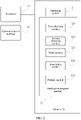
- Step 105 Store the service template that is associated with the service identity in a service type library, and publish the service template to the user.
- a service template includes a service attribute, a service policy, and a service parameter. Then, options of the service template are filled with a service attribute and a service policy that are entered by an operator and a default service parameter, to form a complete service template. Then, the service template is associated with a service identity and published to a user. In a subsequent service provisioning process, an orchestrator or a controller may convert the foregoing service policy into a service configuration, so as to design the service policy into the service template, so that a WAN side service can be orchestrated.
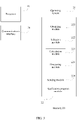
- FIG. 6 is a flowchart of a service provisioning method according to an embodiment of the present invention.
- the service provisioning method is applicable to the orchestrator in the foregoing scenario. Referring to FIG. 6 , the method includes the following steps.
- Step 201 Obtain a service identity entered by a user.
- the service identity includes but is not limited to a service name, a service number, a service identifier, or the like.
- the service name may be an enterprise private line, a personal line, a home line, or the like.
- Step 202 Select a corresponding service template from a service type library according to the service identity, where the service template includes: a service attribute used to describe a service, a service policy used to configure the service, and a service parameter that can be filled in by the user.
- the service attribute may include: a topology type, a service type, a flow configuration, a service level agreement SLA parameter, and a layer parameter.
- the service policy may include: an address pool policy, a QoS policy, a protection policy, and a routing policy.
- the service parameter may include: an identifier of a provider edge PE side access point, bandwidth information, and an SLA parameter.
- Step 203 Calculate inter-domain routing according to the service template.
- the inter-domain routing refers to a data transmission path that passes through multiple domains.
- Step 204 Select, for each domain on a path formed by the calculated inter-domain routing, a single-domain service template used to configure a single domain, where the single-domain service template includes: a service attribute used to describe a service, a service policy used to configure the service, and a service parameter that can be filled in by the user.
- the single-domain service template is a service template applied to a domain, and is used to configure a network element (such as a router) in the domain.
- Step 205 Deliver the single-domain service template to a controller in a corresponding domain, so that the controller configures a network element in the domain.
- an orchestrator when performing service provisioning, first obtains a service identity entered by a user, then selects a corresponding service template for the user according to the service identity entered by the user, calculates inter-domain routing according to the selected service template and selects a single-domain service template that corresponds to each domain, and then delivers the single-domain service template to a controller in the corresponding domain, so as to convert a service policy in the service template into a service configuration and implement the service provisioning.
- FIG. 7 is a flowchart of a service provisioning method according to an embodiment of the present invention.
- the service provisioning method is applicable to the controller in the foregoing scenario. Referring to FIG. 7 , the method includes the following steps.
- Step 301 Receive a single-domain service template delivered by an orchestrator, where the single-domain service template includes: a service attribute used to describe a service, a service policy used to configure the service, and a service parameter that can be filled in by a user.
- the single-domain service template is a service template applied to a domain, and is used to configure a network element (such as a router) in the domain.
- the service attribute may include: a topology type, a service type, a flow configuration, a service level agreement SLA parameter, and a layer parameter.
- the service policy may include: an address pool policy, a QoS policy, a protection policy, and a routing policy.
- the service parameter may include: an identifier of a provider edge PE side access point, bandwidth information, and an SLA parameter.
- Step 302 Calculate intra-domain routing according to the single-domain service template.
- the intra-domain routing refers to a data transmission path that passes through one domain.
- Step 303 Send the intra-domain routing to the orchestrator.
- Step 304 Receive routing information delivered by the orchestrator, where the routing information is generated according to the intra-domain routing and inter-domain routing.
- Step 305 Configure a network element in a domain according to the routing information and the single-domain service template.
- intra-domain routing is calculated by using a single-domain service template. Then, a network element is configured according to routing information obtained by using the intra-domain routing. Finally, a service template is converted into network element configuration in a domain, to implement service orchestration and provisioning.
- FIG. 8 is a flowchart of a service orchestration method useful for understanding the invention.
- the service orchestration method is applicable to the orchestrator in the foregoing scenario.
- a VPN service is used as an example to describe the method provided in FIG. 5 .
- the method includes the following steps.
- Step 401 Obtain a service template, where the service template includes the following options: a service attribute used to describe a service, a service policy used to configure the service, and a service parameter that can be filled in by a user.
- the obtaining a service template may include the following steps.
- a first step Publish a policy management interface by using a northbound interface.
- the policy management interface provides functions such as creation, deletion, and modification of a service type template.
- An operator may use a uniform resource locator (English: Uniform Resource Locator, URL for short) as an entrance, and uses the policy management interface. For example, if a policy management interface that is published by using a restful interface in the northbound interface is used, a URL of the policy management interface may be restful/data/nvo-policy: BusinessTypesMgr/.
- the entrance is provided only to the operator for use, to facilitate service management performed by the operator.
- a second step Obtain the service template by using the policy management interface.
- the service template may be created by the operator.
- the service template includes a first subtemplate applicable to a specified domain on a network and a second subtemplate applicable to a domain on the network other than the specified domain, and the first subtemplate is associated with an identifier of the specified domain.
- a quantity of first subtemplates may be set according to an actual requirement.
- a first subtemplate corresponds to a domain, and may be marked by using an identifier of the domain.
- the operator may determine whether the first subtemplate needs to be designed.
- the operator determines, according to a configuration of each domain on an existing network, whether there is a specified domain.
- a service type applicable to the second subtemplate created by the operator is an L3VPN, and for a domain, the domain does not support the L3VPN, and can support only an L2VPN (or according to a plan, the domain provides only an L2VPN service for the service type).
- the domain cannot use the second subtemplate, and the first subtemplate needs to be created.
- the first subtemplate allows another parameter, such as a tunnel policy, to be different from that of the second subtemplate.
- Step 402 Obtain a service identity, a service attribute, and a service policy that are entered by an operator and a default service parameter.
- the service identity includes but is not limited to a service name, a service number, a service identifier, or the like.
- the service name may be an enterprise private line, a personal line, a home line, or the like.
- the service attribute may include: a topology type, a service type, a flow configuration, a service level agreement SLA parameter, and a layer parameter.
- Parameter Description Topology type It describes a VPN topology type, including point-to-point, point-to-multipoint, or the like.
- Service type It describes a specific VPN layer, including an L2VPN/L3VPN, or the like.
- a flow configuration It describes a flow policy (for different service flow rates) on a VPN and bandwidth information.
- SLA parameter describes an SLA parameter of a VPN.
- Layer parameter describes configuration parameters at different VPN layers, such as a VLAN of an L2VPN, and a routing protocol of an L3VPN.
- the service policy may include: an address pool policy, a QoS policy, a protection policy, and a routing policy.
- All the policies include: a policy level, an application object, and policy content.
- the policy level defines a function level of the policy, including a global policy (which takes effect in an entire orchestration layer management range), a single-domain policy (which is effective for a domain), a service level policy (which is effective for a service type), or a flow level policy (which is effective for a service flow).
- the application object defines a target object to which a policy is applied, including a domain name, a service type name, and a flow template name.
- the foregoing objects are uniquely located by using a name, and multiple object names may be configured at the same time. In this case, a function range overlaps. For example, if the domain name is configured as A, and the service type name is configured as VPN, a function range of the policy is a VPN service of the domain A.
- the policy content differs as a policy type differs. For example, content of the address pool policy is different from content of the routing policy.
- the address pool policy provides planning according to a limited address range of the service type.
- Policy content of the address pool policy is shown in the following table: Parameter Description Route distinguisher (English: Route Distinguisher, RD for short)/route target (English: Route Target, RT for short) pool It supports planning of dividing a RD/RT according to different domains and different service types.
- Internet Protocol English: Internet Protocol, IP for short
- IP Internet Protocol
- Address pool It supports to divide an IP address pool according to different domains and different service types, and is used for IP assignation of a CE access port and an autonomous system boundary router (English: Autonomous System Boundary Router, ASBR for short) port.
- VLAN address pool It supports to divide an IP address pool according to different domains and different service types, and is used for VLAN assignation of a CE access port and an ASBR port.
- the QoS policy provides conversion from a service parameter to a network configuration parameter, such as an adjustment of a committed information rate (English: Committed Information Rate, CIR for short) by a user, automatic calculation of a peak information rate (English: Peak information rate, PIR for short)/peak burst size (English: Peak Burst Size, PBS for short)/committed burst size (English: Committed Burst Size, CBS for short) according to the QoS policy, and a behavior of excessive packet processing.
- Pbs2CirRatio It sets a multiple relationship between a PBS and a CIR and the multiple relationship is 0 by default, that is, a device default value is used.
- Cbs2CirRatio It sets a multiple relationship between a CBS and a CIR and the multiple relationship is 0 by default, that is, a device default value is used.
- Yellow packet processing behavior It defines a yellow packet processing behavior of the service type, such as discarding, or priority remarking.
- Red packet processing behavior It defines a red packet processing behavior of the service type, such as discarding, or priority remarking.
- Lower threshold for bandwidth adjustment It limits a lower threshold for bandwidth adjustment of the service type.
- Upper threshold for bandwidth adjustment limits an upper threshold for bandwidth adjustment of the service type.
- the protection policy provides a protection requirement of the service.
- Policy content of the protection policy is shown in the following table:
- Parameter Description Protection type The protection type includes label switched path (English: Label Switching Path, LSP for short) 1:1, pseudo wire (English: PseudoWire, PW for short) redundancy protection, and the like.
- Protection parameter It includes a wait to restore (English: Wait To Restore, WTR for short) time, a reversion mode (reversion Mode), and the like.
- the routing policy provides a service routing configuration policy. Policy content of the routing policy is shown in the following table: Parameter Description Multiple-domain interconnection policy It describes a mode of the service during inter-domain interconnection, including "Option A, Option B, and Option C", and Option A is used by default. Routing rule The routing rule includes a routing condition and a route condition, where the route condition includes a routing calculation manner such as a shortest path, load balancing, or a shortest delay. The routing condition specifies a limit condition including a resource load upper limit. For example, if the resource load upper limit is 60%, after load of a resource exceeds 60%, the service cannot pass through the resource.
- Tunnel policy The tunnel policy includes a tunnel bearing technology and a tunnel SLA requirement.
- the tunnel bearing technology includes LDP/Generic Routing Encapsulation (English: Generic Routing Encapsulation, GRE for short)/RSVP-TE, and the like.
- the SLA requirement includes a jitter, a delay, and a packet loss rate.
- Path limitation includes a primary/secondary path limitation condition, and may designate an explicit resource pool and an excluded resource pool, where a resource pool is a port set.
- the service parameter may include: an identifier of a provider edge PE side access point and bandwidth information.
- the identifier of the PE side access point indicates an access point at which a user network accesses an operator network, such as a central China access point or a south China access point.
- the bandwidth information may be magnitude of a bandwidth, such as 50 M or 100 M.
- Step 403 Fill in the options of the service template with the service attribute and the service policy that are entered by the operator and the default service parameter.
- the service attribute and the service policy that are entered by the operator and the default service parameter may include a part that is used for the first subtemplate and a part that is used for the second subtemplate, and the first subtemplate and the second subtemplate need to be separately filled in with the service attribute and the service policy that are entered by the operator and the default service parameter.
- Step 404 Associate the service template that is filled in with the service identity.
- a universally unique identifier (English: Universally Unique Identifier, UUID for short) is generated for the service template, and the UUID is associated with the service identity.
- Step 405 Store the service template that is associated with the service identity in a service type library, and publish the service template to the user.
- the publishing the service template to the user may include: publishing a service creation interface by using a northbound interface, so that the user can use the service template in the service type library by using the service creation interface.
- the user may use a URL as an entrance, and uses the service creation interface.
- a URL of the service creation interface may be /restful/data/nvo-vpn: nvoVPNMgr/composedVpns.
- FIG. 9 is a flowchart of a service provisioning method according to an embodiment of the present invention.
- the service provisioning method is applicable to the orchestrator and the controller in the foregoing scenario.
- a VPN service is used as an example to describe the methods provided in FIG. 6 and FIG. 7 .
- the method includes the following steps.
- Step 501 An orchestrator obtains a service identity entered by a user.
- the obtaining a service identity entered by a user includes:
- Step 502 The orchestrator selects a corresponding service template from a service type library according to the service identity, where the service template includes: a service attribute used to describe a service, a service policy used to configure the service, and a service parameter that can be filled in by the user.
- Step 503 The orchestrator calculates inter-domain routing according to the service template.
- the calculating inter-domain routing according to the service template includes the following steps.
- the routing rule includes a routing condition and a route condition.
- the routing condition may be a resource load upper limit
- the route condition may be a shortest path.
- a second step Calculate the inter-domain routing according to the routing condition and the route condition.
- the second step may include: filtering, according to the routing condition, a node that does not satisfy the routing condition and that is on a logical network, where the logical network is obtained by abstracting a domain on a network as a node and by abstracting an inter-domain connection as a path; and calculating the inter-domain routing according to the route condition.
- the resource load upper limit is 50%
- a port and a link of a node that is on the logical network and whose bandwidth consumption exceeds 50% need to be excluded.
- a path having a shortest delay may be selected. Then, after the path selection is completed, a delay is allocated to each domain according to a total delay of the path. A delay that is allocated to each domain is used as a new service parameter. In a subsequent process, the service parameter is used to modify a single-domain service template.
- a third step Assign, according to an address pool policy in the service policy, an address to a port of an edge device (a PE/ASBR) on a path selected by the inter-domain routing.
- a PE/ASBR edge device
- the address includes a VLAN address, an IP address, or the like.
- the IP address needs to be assigned according to an L3VPN path.
- the orchestrator may create a routing list to store the calculated routing information. Specifically, when calculating the inter-domain routing, the orchestrator fills in the routing list with the port of the edge device selected by the inter-domain routing.
- Step 504 The orchestrator selects, for each domain on a path formed by the calculated inter-domain routing, a single-domain service template used to configure a single domain, where the single-domain service template includes: a service attribute used to describe a service, a service policy used to configure the service, and a service parameter that can be filled in by the user.
- the selecting, for each domain on a path selected by the calculated inter-domain routing, a single-domain service template used to configure a single domain includes:
- Step 505 The orchestrator delivers the single-domain service template to a controller in a corresponding domain.
- the method further includes the following steps.
- a first step Obtain a service parameter entered by the user.
- the service parameter includes but is not limited to a PE side access point and bandwidth information, and may further include a parameter for modifying the service attribute in the service template, such as a flow configuration and an SLA parameter.
- a second step Before the single-domain service template is delivered to the controller in the corresponding domain, replace the service parameter in the single-domain service template with the service parameter entered by the user.
- the service parameter herein may include a service parameter that is obtained through calculation according to the directly entered service parameter, such as a delay of each domain described above.
- a third step Deliver the single-domain service template after replacement to the controller in the corresponding domain.
- a default bandwidth defined in the a flow configuration in the single-domain service template is 5 M
- a bandwidth in the service parameter is 10 M
- the original 5 M bandwidth is directly replaced with the 10 M bandwidth.
- a default delay defined in the SLA parameter in the single-domain service template is 100 ms
- a delay in the service parameter is 50 ms
- the original 100 ms delay is directly replaced with the 50 ms delay.
- the orchestrator converts the address pool policy, the routing policy, and the protection policy in the modified single-domain service template and a port and an address of an edge device of each domain into a network level model.
- the orchestrator generates a QoS configuration according to the a flow configuration entered by the user and the QoS policy. For example, the user enters a CIR, and calculates a parameter such as a PIR/PBS/CBS by using the QoS policy.
- the network level model and the Qos configuration are delivered to the controller by using a restful interface to request intra-domain routing.
- the third step may include: converting the single-domain service template into a parameter that can be used by the controller; and delivering the parameter to the controller.
- Step 506 The controller receives the single-domain service template delivered by the orchestrator, where the single-domain service template includes: a service attribute used to describe a service, a service policy used to configure the service, and a service parameter that can be filled in by a user.
- Step 507 The controller calculates intra-domain routing according to the single-domain service template.
- Step one The controller obtains a routing rule from the routing policy in the modified single-domain service template.
- the routing rule includes a routing condition and a route condition.
- the routing condition may be a resource load upper limit
- the route condition may be a shortest path.
- Step two The controller filters, according to the routing rule, a node that does not satisfy the routing condition. For example, if the resource load upper limit is 50%, a port and a link of a node that is on the logical network and whose bandwidth consumption exceeds 50% need to be excluded.
- the service parameters such as a bandwidth and a delay also need to be considered as much as possible. Details are not described herein.
- Step three The controller calculates the intra-domain routing according to the route condition.
- the controller assigns, according to the address pool policy in the modified single-domain service template, an address to a port of a provider (P) device on a path selected by the intra-domain routing.
- Step 508 The controller sends the intra-domain routing to the orchestrator.
- Step 509 The orchestrator receives the intra-domain routing returned by the controller.
- the method further includes: receiving a result code returned by the controller after the controller calculates the intra-domain routing;
- Step 510 The orchestrator combines the intra-domain routing and the inter-domain routing into routing information.
- the method further includes:
- Step 511 The orchestrator sends the routing information to the controller.
- Step 512 The controller receives the routing information delivered by the orchestrator, where the routing information is generated according to the intra-domain routing and the inter-domain routing.
- Step 513 Configure a network element in the domain according to the routing information and the single-domain service template.
- the controller converts the routing information and the modified single-domain service template into a network element level model such as interface configuration of a network element or virtual routing and forwarding table configuration, and writes the configuration in the network element level model obtained through conversion to a device.
- a specific write process may be implemented by using a command line.
- the method further includes:
- FIG. 10 is a block diagram of a service orchestration apparatus useful for understanding the invention.
- the service orchestration apparatus may be implemented as all or a part of an orchestrator by using software, hardware, or a combination of the two.
- the service orchestration apparatus may implement the service orchestration method provided in FIG. 5 or FIG. 8 .
- the service orchestration apparatus may include: a first obtaining unit 601, a second obtaining unit 602, a write unit 603, an association unit 604, and a publish unit 605.
- the first obtaining unit 601, the second obtaining unit 602, and the publish unit 605 may be jointly implemented by using the processor 10 and the communications interface 30 that are in the foregoing orchestrator.
- the write unit 603 and the association unit 604 may be implemented by using the processor 10 in the foregoing orchestrator.
- the first obtaining unit 601 is adapted to obtain a service template, where the service template includes the following options: a service attribute used to describe a service, a service policy used to configure the service, and a service parameter that can be filled in by a user.
- the second obtaining unit 602 is adapted to obtain a service identity, a service attribute, and a service policy that are entered by an operator and a default service parameter.
- the write unit 603 is adapted to fill in the options of the service template with the service attribute and the service policy that are entered by the operator and the default service parameter.
- the association unit 604 is adapted to associate the service template that is filled in with the service identity.
- the publish unit 605 is adapted to: store the service template that is associated with the service identity in a service type library, and publish the service template to the user.
- the first obtaining unit 601 is adapted to:
- the publish unit 605 is adapted to:
- the service template includes a first subtemplate applicable to a specified domain on a network and a second subtemplate applicable to a domain on the network other than the specified domain, and the first subtemplate is associated with an identifier of the specified domain.
- the service is a virtual private network VPN service.
- the service attribute includes: a topology type, a service type, a flow configuration, a service level agreement SLA parameter, and a layer parameter.
- the service policy includes: an address pool policy, a quality of service QoS policy, a protection policy, and a routing policy.
- the service parameter includes an identifier of a provider edge PE side access point and bandwidth information.
- FIG. 11 is a block diagram of a service provisioning apparatus according to an embodiment of the present invention.
- the service provisioning apparatus may be implemented as all or a part of an orchestrator by using software, hardware, or a combination of the two.
- the service provisioning apparatus may implement the service provisioning method provided in FIG. 6 or FIG. 9 .
- the service provisioning apparatus may include: an obtaining unit 701, a selection unit 702, a calculation unit 703, a processing unit 704, and a sending unit 705.
- the obtaining unit 701 and the sending unit 705 may be jointly implemented by using the processor 10 and the communications interface 30 that are in the foregoing orchestrator.
- the selection unit 702, the calculation unit 703, and the processing unit 704 may be implemented by using the processor 10 in the foregoing orchestrator.
- the obtaining unit 701 is adapted to obtain a service identity entered by a user.
- the selection unit 702 is adapted to select a corresponding service template from a service type library according to the service identity, where the service template includes: a service attribute used to describe a service, a service policy used to configure the service, and a service parameter that can be filled in by the user.
- the calculation unit 703 is adapted to calculate inter-domain routing according to the service template.
- the processing unit 704 is adapted to select, for each domain on a path formed by the calculated inter-domain routing, a single-domain service template used to configure a single domain, where the single-domain service template includes: a service attribute used to describe a service, a service policy used to configure the service, and a service parameter that can be filled in by the user.
- the sending unit 705 is adapted to deliver the single-domain service template to a controller in a corresponding domain, so that the controller configures a network element in the domain.
- the obtaining unit 701 is adapted to:
- the calculation unit 703 is adapted to:
- the calculation unit 703 is optionally adapted to: filter, according to the routing condition, a node that does not satisfy the routing condition and that is on a logical network, where the logical network is obtained by abstracting a domain on a network as a node and by abstracting an inter-domain connection as a path; and calculate the inter-domain routing according to the route condition.
- processing unit 704 is adapted to:
- the sending unit 705 is adapted to: deliver the single-domain service template to the controller in the corresponding domain to request intra-domain routing.
- the apparatus further includes:
- the obtaining unit 701 is further adapted to obtain a service parameter entered by the user;
- the receiving unit 706 is further adapted to receive a result code returned by the controller after the controller calculates the intra-domain routing;
- the sending unit 705 is further adapted to return the routing information to an operator;
- the receiving unit 706 is further adapted to receive a configuration result of the controller; and the processing unit 704 is further adapted to: if all domains are successfully configured, set a status of the service to active; if some domains fail to be configured, set the status of the service to partially-successful; or if all domains fail to be configured, set the status of the service to inactive.
- the service is a VPN service.
- FIG. 12 is a block diagram of a service provisioning apparatus according to an embodiment of the present invention.
- the service provisioning apparatus may be implemented as all or a part of a controller by using software, hardware, or a combination of the two.
- the service provisioning apparatus may implement the service provisioning method provided in FIG. 7 or FIG. 9 .
- the service provisioning apparatus may include: a first receiving unit 801, a calculation unit 802, a sending unit 803, a second receiving unit 804, and a configuration unit 805.
- the first receiving unit 801, the sending unit 803, and the second receiving unit 804 may be jointly implemented by using the processor 10 and the communications interface 30 that are in the foregoing orchestrator.
- the calculation unit 802 and the configuration unit 805 may be implemented by using the processor 10 in the foregoing orchestrator.
- the first receiving unit 801 is adapted to receive a single-domain service template delivered by an orchestrator, where the single-domain service template includes: a service attribute used to describe a service, a service policy used to configure the service, and a service parameter that can be filled in by a user.
- the calculation unit 802 is adapted to calculate intra-domain routing according to the single-domain service template.
- the sending unit 803 is adapted to send the intra-domain routing to the orchestrator.
- the second receiving unit 804 is adapted to receive routing information delivered by the orchestrator, where the routing information is generated according to the intra-domain routing and inter-domain routing.
- the configuration unit 805 is adapted to configure a network element in a domain according to the routing information and the single-domain service template.
- FIG. 13 is a block diagram of a service provisioning system according to an embodiment of the present invention.
- the system includes an orchestrator 901 and a controller 902.
- the orchestrator 901 includes the service orchestration apparatus shown in FIG. 10 and the service provisioning apparatus shown in FIG. 11 .
- the controller 902 includes the service provisioning apparatus shown in FIG. 12 .
- the service orchestration apparatus when performing service orchestration, is merely described by using an example of division of the foregoing functional units. During actual application, the foregoing functions can be allocated to different functional units and implemented according to a requirement, that is, an inner structure of the device is divided into different functional units to complete all or some of the functions described above. In addition, the service orchestration apparatus and the service orchestration method fall within a same conception. For details of a specific implementation procedure of the service orchestration apparatus, refer to the method embodiment. The details are not described herein again.
- the service provisioning apparatus provided in the foregoing embodiment is merely described by using an example of division of the foregoing functional units.
- the foregoing functions can be allocated to different functional units and implemented according to a requirement, that is, an inner structure of the device is divided into different functional units to complete all or some of the functions described above.
- the service provisioning apparatus provided in the foregoing embodiment and the embodiments of the service provisioning method fall within a same conception. For details of a specific implementation procedure of the service provisioning apparatus, refer to the method embodiment. The details are not described herein again.
- the program may be stored in a computer-readable storage medium.
- the storage medium may be a read-only memory, a magnetic disk, an optical disc, or the like.
Landscapes
- Engineering & Computer Science (AREA)
- Computer Networks & Wireless Communication (AREA)
- Signal Processing (AREA)
- Computer Security & Cryptography (AREA)
- Data Exchanges In Wide-Area Networks (AREA)
Claims (9)
- Dienstbereitstellungsverfahren, wobei das Verfahren umfasst:Erhalten einer Dienstidentität, die durch einen Benutzer eingegeben wird;Auswählen einer entsprechenden Dienstvorlage aus einer Diensttypbibliothek gemäß der Dienstidentität, wobei die Dienstvorlage Folgendes umfasst: ein Dienstattribut, das verwendet wird, um einen Dienst zu beschreiben, eine Dienstrichtlinie, die verwendet wird, um den Dienst zu konfigurieren, und einen Dienstparameter, der durch den Benutzer ausgefüllt werden kann;Berechnen eines Inter-Domain-Routings gemäß dem Dienstattribut und der Dienstrichtlinie der Dienstvorlage, um einen Inter-Domain-Routingpfad auszubilden, der durch mehrere Domains verläuft;Auswählen, für jede Domain (10) auf dem Inter-Domain-Routingpfad, einer Einzel-Domain-Dienstvorlage, die verwendet wird, um eine Einzel-Domain zu konfigurieren, wobei die Einzel-Domain-Dienstvorlage Folgendes umfasst: ein Dienstattribut, das verwendet wird, um einen Dienst zu beschreiben, eine Dienstrichtlinie, die verwendet wird, um den Dienst zu konfigurieren, und einen Dienstparameter, der durch den Benutzer ausgefüllt werden kann; undLiefern der Einzel-Domain-Dienstvorlage an eine Steuerung (200, 902) in einer entsprechenden Domain (10), so dass die Steuerung ein Netzwerkelement in der Domain konfiguriert,wobei das Berechnen des Inter-Domain-Routings gemäß der Dienstvorlage Folgendes umfasst:Erhalten einer Routingregel von der Dienstrichtlinie in der Dienstvorlage, wobei die Routingregel eine Routing-Bedingung und eine Route-Bedingung umfasst;Berechnen des Inter-Domain-Routings gemäß der Routing-Bedingung und der Route-Bedingung; undZuweisen, gemäß einer Adresspoolrichtlinie in der Dienstrichtlinie, einer Adresse zu einem Anschluss einer Edge-Einrichtung auf einem Pfad, der durch das Inter-Domain-Routing ausgebildet wird.
- Verfahren nach Anspruch 1, wobei das Berechnen des Inter-Domain-Routings gemäß der Routing-Bedingung und der Route-Bedingung Folgendes beinhaltet: Filtern, gemäß der Routing-Bedingung, eines Knotens, der die Routing-Bedingung nicht erfüllt und sich in einem logischen Netzwerk befindet, wobei das logische Netzwerk durch ein Abstrahieren einer Domain in einem Netzwerk als ein Knoten und durch ein Abstrahieren einer Inter-Domain-Verbindung als einen Pfad erhalten wird; und Berechnen des Inter-Domain-Routings gemäß der Route-Bedingung.
- Verfahren nach Anspruch 1, wobei das Erhalten einer Dienstidentität, die durch einen Benutzer eingegeben wird, umfasst:
Erhalten, durch Verwenden einer Diensterzeugungsschnittstelle, der Dienstidentität, die durch den Benutzer eingegeben wird, wobei die Diensterzeugungsschnittstelle durch Verwenden einer nach Norden gerichteten Schnittstelle veröffentlicht wird. - Verfahren nach Anspruch 1, wobei das Auswählen, für jede Domain (10) auf einem Pfad, der durch das berechnete Inter-Domain-Routing ausgebildet wird, einer Einzel-Domain-Dienstvorlage, die verwendet wird, um eine Einzel-Domain zu konfigurieren, Folgendes umfasst:Bestimmen, ob eine Domain (10) eine spezifizierte Domain ist; undwenn die Domain (10) eine spezifizierte Domain ist, Auswählen einer ersten Teilvorlage als eine Einzel-Domain-Dienstvorlage der Domain und wenn die Domain keine spezifizierte Domain ist, Auswählen einer zweiten Teilvorlage als die Einzel-Domain-Dienstvorlage der Domain, wobei die Dienstvorlage die erste Teilvorlage, die auf die spezifizierte Domain in einem Netzwerk (20) anwendbar ist, und die zweite Teilvorlage umfasst, die auf eine andere Domain in dem Netzwerk als die spezifizierte Domain anwendbar ist, und wobei die erste Teilvorlage einem Bezeichner der spezifizierten Domain zugeordnet ist.
- Verfahren nach Anspruch 1, wobei das Liefern der Einzel-Domain-Dienstvorlage an eine Steuerung (200, 902) in einer entsprechenden Domain (10), so dass die Steuerung ein Netzwerkelement in der Domain konfiguriert, Folgendes umfasst:Liefern der Einzel-Domain-Dienstvorlage an die Steuerung (200, 902) in der entsprechenden Domain (10), um ein Intra-Domain-Routing anzufordern;Empfangen des Intra-Domain-Routings, das durch die Steuerung (200, 902) zurückgegeben wird;Kombinieren des Intra-Domain-Routings und des Inter-Domain-Routings zu Routing-Informationen; undLiefern der Routing-Informationen an die Steuerung (200, 902), so dass die Steuerung das Netzwerkelement in der Domain (10) gemäß den Routing-Informationen und der Einzel-Domain-Dienstvorlage konfiguriert.
- Dienstverwaltungseinrichtung, wobei die Einrichtung Folgendes umfasst:eine Erhaltungseinheit (601, 602, 701), die angepasst ist, um eine Dienstidentität zu erhalten, die durch einen Benutzer eingegeben wird; eine Auswahleinheit (702), die angepasst ist, um eine entsprechende Dienstvorlage aus einer Diensttypbibliothek gemäß der Dienstidentität auszuwählen, wobei die Dienstvorlage Folgendes umfasst: ein Dienstattribut, das verwendet wird, um einen Dienst zu beschreiben, eine Dienstrichtlinie, die verwendet wird, um den Dienst zu konfigurieren, und einen Dienstparameter, der durch den Benutzer ausgefüllt werden kann;eine Berechnungseinheit (703, 802), die angepasst ist, um das Inter-Domain-Routing gemäß dem Dienstattribut und der Dienstrichtlinie der Dienstvorlage zu berechnen, um einen Inter-Domain-Routingpfad auszubilden, der durch mehrere Domains verläuft;eine Verarbeitungseinheit (704), die angepasst ist, um für jede Domain (10) auf dem Inter-Domain-Routingpfad eine Einzel-Domain-Dienstvorlage auszuwählen, die verwendet wird, um eine Einzel-Domain zu konfigurieren, wobei die Einzel-Domain-Dienstvorlage Folgendes umfasst: ein Dienstattribut, das verwendet wird, um einen Dienst zu beschreiben, eine Dienstrichtlinie, die verwendet wird, um den Dienst zu konfigurieren, und einen Dienstparameter, der durch den Benutzer ausgefüllt werden kann; undeine Sendeeinheit (705, 803), die angepasst ist, um die Einzel-Domain-Dienstvorlage an eine Steuerung (200, 902) in einer entsprechenden Domain (10) zu liefern, so dass die Steuerung aktiviert wird, ein Netzwerkelement in der Domain zu konfigurieren,wobei die Berechnungseinheit (703, 802) ferner für Folgendes angepasst ist:Erhalten einer Routingregel aus der Dienstrichtlinie in der Dienstvorlage, wobei die Routingregel eine Routing-Bedingung und eine Route-Bedingung umfasst;Berechnen des Inter-Domain-Routings gemäß der Routing-Bedingung und der Route-Bedingung; undZuweisen, gemäß einer Adresspoolrichtlinie in der Dienstrichtlinie, einer Adresse zu einem Anschluss einer Edge-Einrichtung auf einem Pfad, der durch das Inter-Domain-Routing ausgebildet wird.
- Einrichtung nach Anspruch 6, wobei die Berechnungseinheit (703, 802) für Folgendes angepasst ist:Filtern, gemäß der Routing-Bedingung, eines Knotens, der die Routing-Bedingung nicht erfüllt und sich in einem logischen Netzwerk befindet, wobei das logische Netzwerk durch ein Abstrahieren einer Domain in einem Netzwerk als ein Knoten und durch ein Abstrahieren einer Inter-Domain-Verbindung als einen Pfad erhalten wird; undBerechnen des Inter-Domain-Routings gemäß der Route-Bedingung.
- Einrichtung nach Anspruch 6, wobei die Erhaltungseinheit (601, 602, 701) ferner für Folgendes angepasst ist:
Erhalten, durch Verwenden einer Diensterzeugungsschnittstelle, der Dienstidentität, die durch den Benutzer eingegeben wird, wobei die Diensterzeugungsschnittstelle durch Verwenden einer nach Norden gerichteten Schnittstelle veröffentlicht wird. - Einrichtung nach Anspruch 6, wobei die Verarbeitungseinheit (704) für Folgendes angepasst ist: Bestimmen, ob eine Domain (10) eine spezifizierte Domain ist; und
wenn die Domain eine spezifizierte Domain ist, Auswählen einer ersten Teilvorlage als eine Einzel-Domain-Dienstvorlage der Domain, und wenn die Domain keine spezifizierte Domain ist, Auswählen einer zweiten Teilvorlage als eine Einzel-Domain-Dienstvorlage der Domain, wobei die Dienstvorlage die erste Teilvorlage, die auf die spezifizierte Domain in einem Netzwerk anwendbar ist, und die zweite Teilvorlage umfasst, die auf eine andere Domain in dem Netzwerk als die spezifizierte Domain anwendbar ist, und wobei die erste Teilvorlage einem Bezeichner der spezifizierten Domain zugeordnet ist.
Applications Claiming Priority (2)
| Application Number | Priority Date | Filing Date | Title |
|---|---|---|---|
| CN201610717752.9A CN107786353B (zh) | 2016-08-24 | 2016-08-24 | 业务编排方法及装置、业务发放方法及装置 |
| PCT/CN2017/080071 WO2018036172A1 (zh) | 2016-08-24 | 2017-04-11 | 业务编排方法及装置、业务发放方法及装置 |
Publications (3)
| Publication Number | Publication Date |
|---|---|
| EP3402124A1 EP3402124A1 (de) | 2018-11-14 |
| EP3402124A4 EP3402124A4 (de) | 2019-04-24 |
| EP3402124B1 true EP3402124B1 (de) | 2022-11-16 |
Family
ID=61246346
Family Applications (1)
| Application Number | Title | Priority Date | Filing Date |
|---|---|---|---|
| EP17842597.1A Active EP3402124B1 (de) | 2016-08-24 | 2017-04-11 | Dienstausstellungsverfahren und -vorrichtung |
Country Status (4)
| Country | Link |
|---|---|
| US (2) | US11018940B2 (de) |
| EP (1) | EP3402124B1 (de) |
| CN (2) | CN107786353B (de) |
| WO (1) | WO2018036172A1 (de) |
Families Citing this family (23)
| Publication number | Priority date | Publication date | Assignee | Title |
|---|---|---|---|---|
| US10931629B2 (en) | 2016-05-27 | 2021-02-23 | Cisco Technology, Inc. | Techniques for managing software defined networking controller in-band communications in a data center network |
| JP6805194B2 (ja) * | 2018-02-15 | 2020-12-23 | 日本電信電話株式会社 | 経路情報転送装置、経路情報転送方法および経路情報転送プログラム |
| CN110324159B (zh) * | 2018-03-28 | 2020-11-03 | 华为技术有限公司 | 链路配置方法、控制器和存储介质 |
| CN110740053B (zh) * | 2018-07-20 | 2022-07-01 | 中国移动通信集团浙江有限公司 | 业务编排方法及装置 |
| CN108847995A (zh) * | 2018-08-01 | 2018-11-20 | 平安科技(深圳)有限公司 | 一种基于私有云的配置运维告警模板的方法及设备 |
| CN109379217B (zh) * | 2018-09-27 | 2019-09-20 | 中国联合网络通信有限公司广东省分公司 | 一种城域网异厂家业务编排器 |
| CN111371683B (zh) * | 2018-12-25 | 2021-06-29 | 华为技术有限公司 | 网络连接路径的判定方法、设备及通信系统 |
| US11182800B2 (en) | 2019-04-08 | 2021-11-23 | Bank Of America Corporation | Controlling enterprise software policy compliance assessment processes based on quantum combinations of assessment elements |
| CN110543302A (zh) * | 2019-09-05 | 2019-12-06 | 无锡华云数据技术服务有限公司 | 资源编排过程中输入参数的输入方法及装置 |
| CN110597216B (zh) * | 2019-09-30 | 2022-02-22 | 歌尔股份有限公司 | 制造执行系统的事务编排方法、装置及可读存储介质 |
| CN110958170B (zh) * | 2019-11-25 | 2021-09-14 | 中国联合网络通信集团有限公司 | 一种网络互联方法和装置 |
| US11330064B2 (en) | 2019-12-04 | 2022-05-10 | At&T Intellectual Property I, L.P. | Method and apparatus to facilitate a multi-point connection with a communication device |
| CN111147377B (zh) * | 2019-12-05 | 2020-09-11 | 连连银通电子支付有限公司 | 一种业务通道的确定方法、装置、设备和介质 |
| CN111030874B (zh) * | 2019-12-24 | 2022-09-30 | 深信服科技股份有限公司 | 业务编排方法、设备、存储介质及装置 |
| CN114050966B (zh) * | 2020-07-22 | 2023-01-06 | 华为技术有限公司 | 业务模板的生成方法、装置、设备及存储介质 |
| CN112491977B (zh) * | 2020-11-12 | 2022-01-11 | 中国建设银行股份有限公司 | 一种目标业务数据发布方法、系统、装置及介质 |
| US11252082B1 (en) * | 2020-11-13 | 2022-02-15 | Juniper Networks, Inc. | Filtering topologies for path computation in massively scaled networks |
| CN112527254B (zh) * | 2020-12-04 | 2024-06-28 | 佰聆数据股份有限公司 | 基于服务编排的业务策略设计方法、系统及计算机设备 |
| CN115529274B (zh) * | 2021-06-24 | 2024-06-18 | 中移(苏州)软件技术有限公司 | 一种网络限速方法及设备 |
| US11575596B1 (en) * | 2022-03-07 | 2023-02-07 | Ciena Corporation | Identifying an ingress router of a flow in inter-AS VPN option-C networks with visibility in one AS |
| CN114780228B (zh) * | 2022-06-23 | 2022-09-16 | 浙江九州云信息科技有限公司 | 一种混合云资源创建方法及系统 |
| CN115913959A (zh) * | 2022-12-27 | 2023-04-04 | 中国电信股份有限公司 | 基于模板的设备配置方法、装置及电子设备 |
| US20250126120A1 (en) * | 2023-10-15 | 2025-04-17 | VMware LLC | Converting enforcement policy information into provisioning template information |
Family Cites Families (21)
| Publication number | Priority date | Publication date | Assignee | Title |
|---|---|---|---|---|
| WO2002006973A1 (en) * | 2000-07-13 | 2002-01-24 | Aprisma Management Technologies, Inc. | Method and apparatus for automated service provisioning across multiple networking technologies |
| US20030144885A1 (en) * | 2002-01-29 | 2003-07-31 | Exscribe, Inc. | Medical examination and transcription method, and associated apparatus |
| US8554916B2 (en) * | 2005-04-11 | 2013-10-08 | Accenture Global Services Gmbh | Service delivery platform and development of new client business models |
| US20070283273A1 (en) * | 2005-10-24 | 2007-12-06 | Woods Michael E | System, Method, and Computer Program Product for Internet Tool |
| CN100512303C (zh) * | 2006-02-17 | 2009-07-08 | 华为技术有限公司 | 一种跨域业务域内域间映射关系的确定方法 |
| US8122110B1 (en) * | 2006-06-30 | 2012-02-21 | Rockstar Bidco, LP | Active configuration templating |
| CN102118370B (zh) * | 2009-12-31 | 2014-12-31 | 华为技术有限公司 | 业务管理方法、装置和系统 |
| US9838370B2 (en) * | 2012-09-07 | 2017-12-05 | Oracle International Corporation | Business attribute driven sizing algorithms |
| CN102882722B (zh) * | 2012-09-28 | 2015-04-15 | 烽火通信科技股份有限公司 | Ptn/ipran端到端业务数据快速创建方法 |
| US8726343B1 (en) * | 2012-10-12 | 2014-05-13 | Citrix Systems, Inc. | Managing dynamic policies and settings in an orchestration framework for connected devices |
| CN103051565B (zh) * | 2013-01-04 | 2018-01-05 | 中兴通讯股份有限公司 | 一种等级软件定义网络控制器的架构系统及实现方法 |
| US9722885B2 (en) * | 2013-08-08 | 2017-08-01 | Level 3 Communications, Llc | Content delivery methods and systems |
| US9385926B2 (en) * | 2013-12-19 | 2016-07-05 | Intel Corporation | Service template generation and deployment based on service level agreement requirements |
| CN104811326A (zh) * | 2014-01-24 | 2015-07-29 | 中兴通讯股份有限公司 | 一种管理业务链的方法、系统及装置 |
| CN103942052B (zh) * | 2014-04-17 | 2017-11-03 | 中国联合网络通信集团有限公司 | 一种业务容器引擎 |
| CN105207798B (zh) | 2014-06-26 | 2020-03-13 | 中兴通讯股份有限公司 | 软件定义网络中的业务编排方法及装置 |
| US9800673B2 (en) * | 2014-08-20 | 2017-10-24 | At&T Intellectual Property I, L.P. | Service compiler component and service controller for open systems interconnection layer 4 through layer 7 services in a cloud computing system |
| CN105577549B (zh) | 2014-10-13 | 2019-11-19 | 中兴通讯股份有限公司 | 一种基于软件定义网络实现内容分发网络的方法及系统 |
| US9893887B2 (en) * | 2015-01-30 | 2018-02-13 | Ciena Corporation | Dynamic licensing for applications and plugin framework for virtual network systems |
| CN104836853A (zh) * | 2015-04-22 | 2015-08-12 | 华为技术有限公司 | 编排业务的方法及装置 |
| EP3366016A1 (de) * | 2015-10-22 | 2018-08-29 | Nokia Solutions and Networks Oy | Sicherheitsmechanismus für kommunikationsnetz mit virtuellen netzwerkfunktionen |
-
2016
- 2016-08-24 CN CN201610717752.9A patent/CN107786353B/zh active Active
- 2016-08-24 CN CN202010495830.1A patent/CN111865653B/zh active Active
-
2017
- 2017-04-11 EP EP17842597.1A patent/EP3402124B1/de active Active
- 2017-04-11 WO PCT/CN2017/080071 patent/WO2018036172A1/zh not_active Ceased
-
2018
- 2018-08-14 US US16/103,290 patent/US11018940B2/en active Active
-
2021
- 2021-04-26 US US17/240,775 patent/US11368370B2/en active Active
Non-Patent Citations (1)
| Title |
|---|
| DOLSON SANDVINE S HOMMA NTT D LOPEZ TELEFONICA I+D M BOUCADAIR ORANGE D LIU ALIBABA GROUP T AO ZTE CORPORATION V VU SSU D: "Hierarchical Service Function Chaining (hSFC); draft-ietf-sfc-hierarchical-00.txt", HIERARCHICAL SERVICE FUNCTION CHAINING (HSFC); DRAFT-IETF-SFC-HIERARCHICAL-00.TXT, INTERNET ENGINEERING TASK FORCE, IETF; STANDARDWORKINGDRAFT, INTERNET SOCIETY (ISOC) 4, RUE DES FALAISES CH- 1205 GENEVA, SWITZERLAND, 26 July 2016 (2016-07-26), pages 1 - 23, XP015114610 * |
Also Published As
| Publication number | Publication date |
|---|---|
| CN107786353A (zh) | 2018-03-09 |
| EP3402124A1 (de) | 2018-11-14 |
| US11368370B2 (en) | 2022-06-21 |
| EP3402124A4 (de) | 2019-04-24 |
| CN111865653A (zh) | 2020-10-30 |
| WO2018036172A1 (zh) | 2018-03-01 |
| CN111865653B (zh) | 2025-06-17 |
| CN107786353B (zh) | 2020-06-26 |
| US20210250242A1 (en) | 2021-08-12 |
| US20180367409A1 (en) | 2018-12-20 |
| US11018940B2 (en) | 2021-05-25 |
Similar Documents
| Publication | Publication Date | Title |
|---|---|---|
| EP3402124B1 (de) | Dienstausstellungsverfahren und -vorrichtung | |
| EP4149081A1 (de) | Automatische anwendungsbasierte mehrpfad-leitweglenkung für einen sd-wan-dienst | |
| US12143385B2 (en) | Role-based access control policy auto generation | |
| CN111130980B (zh) | 用于实现组合虚拟专用网vpn的方法与装置 | |
| KR20150038323A (ko) | 폴리시 기반 데이터센터 네트워크 자동화를 제공하는 시스템 및 방법 | |
| CN104104534A (zh) | 一种虚拟网络管理的实现方法和系统 | |
| US20150026332A1 (en) | Method and Apparatus to Securely Process Streams of Data of Network / Storage / Compute Devices of Private Enterprise Clouds in Real-time from the Public Cloud | |
| US20140351648A1 (en) | Method and Apparatus for Dynamic Correlation of Large Cloud Firewall Fault Event Stream | |
| US20140351920A1 (en) | Method and Apparatus for Dynamic Tunneling | |
| Chung et al. | Advance reservation access control using software-defined networking and tokens | |
| US20140351423A1 (en) | Method and Apparatus for Dynamic Correlation of Large Cloud Firewall Fault Event Stream | |
| EP2816774A1 (de) | System zur Durchsetzung der Privatsphäre in einem Telekommunikationsnetzwerk | |
| US20140351649A1 (en) | Method and Apparatus for Dynamic Correlation of Large Cloud Compute Fault Event Stream | |
| Mendiola et al. | DynPaC: A path computation framework for SDN | |
| US20140351429A1 (en) | Method and Apparatus to Elastically Modify Size of a Resource Pool | |
| WO2017182086A1 (en) | Management of network resources shared by multiple customers | |
| US20140351437A1 (en) | Method and apparatus for policy based elastic computing | |
| Toy | Future Directions in Cable Networks, Services and Management | |
| Belter et al. | The geysers optical testbed: A platform for the integration, validation and demonstration of cloud-based infrastructure services | |
| US20140351647A1 (en) | Method and Apparatus for Dynamic Correlation of Large Cloud Load Balancing Fault Event Stream | |
| Vilalta et al. | Experimental validation of resource allocation in transport network slicing using the ADRENALINE testbed | |
| KR100543446B1 (ko) | 레이블 스위칭 경로의 트래픽 측정을 위한 성능 관리 방법 | |
| US20140351657A1 (en) | Method and Apparatus for a Predictable Cloud Infrastructure Assurance Model | |
| US20140344450A1 (en) | Method and Apparatus for Deterministic Cloud User Service Impact Reporting | |
| US20140351646A1 (en) | Method and Apparatus for Dynamic Correlation of Large Network Compute Fault Event Stream |
Legal Events
| Date | Code | Title | Description |
|---|---|---|---|
| STAA | Information on the status of an ep patent application or granted ep patent |
Free format text: STATUS: THE INTERNATIONAL PUBLICATION HAS BEEN MADE |
|
| PUAI | Public reference made under article 153(3) epc to a published international application that has entered the european phase |
Free format text: ORIGINAL CODE: 0009012 |
|
| STAA | Information on the status of an ep patent application or granted ep patent |
Free format text: STATUS: REQUEST FOR EXAMINATION WAS MADE |
|
| 17P | Request for examination filed |
Effective date: 20180807 |
|
| AK | Designated contracting states |
Kind code of ref document: A1 Designated state(s): AL AT BE BG CH CY CZ DE DK EE ES FI FR GB GR HR HU IE IS IT LI LT LU LV MC MK MT NL NO PL PT RO RS SE SI SK SM TR |
|
| AX | Request for extension of the european patent |
Extension state: BA ME |
|
| RIC1 | Information provided on ipc code assigned before grant |
Ipc: H04L 12/715 20130101ALI20190122BHEP Ipc: H04L 12/721 20130101ALI20190122BHEP Ipc: H04L 12/24 20060101AFI20190122BHEP Ipc: H04L 12/46 20060101ALI20190122BHEP |
|
| A4 | Supplementary search report drawn up and despatched |
Effective date: 20190325 |
|
| RIC1 | Information provided on ipc code assigned before grant |
Ipc: H04L 12/715 20130101ALI20190319BHEP Ipc: H04L 12/721 20130101ALI20190319BHEP Ipc: H04L 12/24 20060101AFI20190319BHEP Ipc: H04L 12/46 20060101ALI20190319BHEP |
|
| DAV | Request for validation of the european patent (deleted) | ||
| DAX | Request for extension of the european patent (deleted) | ||
| STAA | Information on the status of an ep patent application or granted ep patent |
Free format text: STATUS: EXAMINATION IS IN PROGRESS |
|
| 17Q | First examination report despatched |
Effective date: 20200304 |
|
| REG | Reference to a national code |
Ref country code: DE Ref legal event code: R079 Ref document number: 602017063819 Country of ref document: DE Free format text: PREVIOUS MAIN CLASS: H04L0012240000 Ipc: H04L0041504100 |
|
| GRAP | Despatch of communication of intention to grant a patent |
Free format text: ORIGINAL CODE: EPIDOSNIGR1 |
|
| STAA | Information on the status of an ep patent application or granted ep patent |
Free format text: STATUS: GRANT OF PATENT IS INTENDED |
|
| RIC1 | Information provided on ipc code assigned before grant |
Ipc: H04L 41/40 20220101ALI20220511BHEP Ipc: H04L 45/02 20220101ALI20220511BHEP Ipc: H04L 45/64 20220101ALI20220511BHEP Ipc: H04L 45/00 20220101ALI20220511BHEP Ipc: H04L 41/044 20220101ALI20220511BHEP Ipc: H04L 41/5054 20220101ALI20220511BHEP Ipc: H04L 41/5041 20220101AFI20220511BHEP |
|
| INTG | Intention to grant announced |
Effective date: 20220610 |
|
| GRAS | Grant fee paid |
Free format text: ORIGINAL CODE: EPIDOSNIGR3 |
|
| GRAA | (expected) grant |
Free format text: ORIGINAL CODE: 0009210 |
|
| STAA | Information on the status of an ep patent application or granted ep patent |
Free format text: STATUS: THE PATENT HAS BEEN GRANTED |
|
| AK | Designated contracting states |
Kind code of ref document: B1 Designated state(s): AL AT BE BG CH CY CZ DE DK EE ES FI FR GB GR HR HU IE IS IT LI LT LU LV MC MK MT NL NO PL PT RO RS SE SI SK SM TR |
|
| REG | Reference to a national code |
Ref country code: GB Ref legal event code: FG4D |
|
| REG | Reference to a national code |
Ref country code: CH Ref legal event code: EP |
|
| REG | Reference to a national code |
Ref country code: DE Ref legal event code: R096 Ref document number: 602017063819 Country of ref document: DE |
|
| REG | Reference to a national code |
Ref country code: IE Ref legal event code: FG4D |
|
| REG | Reference to a national code |
Ref country code: AT Ref legal event code: REF Ref document number: 1532454 Country of ref document: AT Kind code of ref document: T Effective date: 20221215 |
|
| REG | Reference to a national code |
Ref country code: LT Ref legal event code: MG9D |
|
| REG | Reference to a national code |
Ref country code: NL Ref legal event code: MP Effective date: 20221116 |
|
| REG | Reference to a national code |
Ref country code: AT Ref legal event code: MK05 Ref document number: 1532454 Country of ref document: AT Kind code of ref document: T Effective date: 20221116 |
|
| PG25 | Lapsed in a contracting state [announced via postgrant information from national office to epo] |
Ref country code: SE Free format text: LAPSE BECAUSE OF FAILURE TO SUBMIT A TRANSLATION OF THE DESCRIPTION OR TO PAY THE FEE WITHIN THE PRESCRIBED TIME-LIMIT Effective date: 20221116 Ref country code: PT Free format text: LAPSE BECAUSE OF FAILURE TO SUBMIT A TRANSLATION OF THE DESCRIPTION OR TO PAY THE FEE WITHIN THE PRESCRIBED TIME-LIMIT Effective date: 20230316 Ref country code: NO Free format text: LAPSE BECAUSE OF FAILURE TO SUBMIT A TRANSLATION OF THE DESCRIPTION OR TO PAY THE FEE WITHIN THE PRESCRIBED TIME-LIMIT Effective date: 20230216 Ref country code: LT Free format text: LAPSE BECAUSE OF FAILURE TO SUBMIT A TRANSLATION OF THE DESCRIPTION OR TO PAY THE FEE WITHIN THE PRESCRIBED TIME-LIMIT Effective date: 20221116 Ref country code: FI Free format text: LAPSE BECAUSE OF FAILURE TO SUBMIT A TRANSLATION OF THE DESCRIPTION OR TO PAY THE FEE WITHIN THE PRESCRIBED TIME-LIMIT Effective date: 20221116 Ref country code: ES Free format text: LAPSE BECAUSE OF FAILURE TO SUBMIT A TRANSLATION OF THE DESCRIPTION OR TO PAY THE FEE WITHIN THE PRESCRIBED TIME-LIMIT Effective date: 20221116 Ref country code: AT Free format text: LAPSE BECAUSE OF FAILURE TO SUBMIT A TRANSLATION OF THE DESCRIPTION OR TO PAY THE FEE WITHIN THE PRESCRIBED TIME-LIMIT Effective date: 20221116 |
|
| PG25 | Lapsed in a contracting state [announced via postgrant information from national office to epo] |
Ref country code: RS Free format text: LAPSE BECAUSE OF FAILURE TO SUBMIT A TRANSLATION OF THE DESCRIPTION OR TO PAY THE FEE WITHIN THE PRESCRIBED TIME-LIMIT Effective date: 20221116 Ref country code: PL Free format text: LAPSE BECAUSE OF FAILURE TO SUBMIT A TRANSLATION OF THE DESCRIPTION OR TO PAY THE FEE WITHIN THE PRESCRIBED TIME-LIMIT Effective date: 20221116 Ref country code: LV Free format text: LAPSE BECAUSE OF FAILURE TO SUBMIT A TRANSLATION OF THE DESCRIPTION OR TO PAY THE FEE WITHIN THE PRESCRIBED TIME-LIMIT Effective date: 20221116 Ref country code: IS Free format text: LAPSE BECAUSE OF FAILURE TO SUBMIT A TRANSLATION OF THE DESCRIPTION OR TO PAY THE FEE WITHIN THE PRESCRIBED TIME-LIMIT Effective date: 20230316 Ref country code: HR Free format text: LAPSE BECAUSE OF FAILURE TO SUBMIT A TRANSLATION OF THE DESCRIPTION OR TO PAY THE FEE WITHIN THE PRESCRIBED TIME-LIMIT Effective date: 20221116 Ref country code: GR Free format text: LAPSE BECAUSE OF FAILURE TO SUBMIT A TRANSLATION OF THE DESCRIPTION OR TO PAY THE FEE WITHIN THE PRESCRIBED TIME-LIMIT Effective date: 20230217 |
|
| PG25 | Lapsed in a contracting state [announced via postgrant information from national office to epo] |
Ref country code: NL Free format text: LAPSE BECAUSE OF FAILURE TO SUBMIT A TRANSLATION OF THE DESCRIPTION OR TO PAY THE FEE WITHIN THE PRESCRIBED TIME-LIMIT Effective date: 20221116 |
|
| PG25 | Lapsed in a contracting state [announced via postgrant information from national office to epo] |
Ref country code: SM Free format text: LAPSE BECAUSE OF FAILURE TO SUBMIT A TRANSLATION OF THE DESCRIPTION OR TO PAY THE FEE WITHIN THE PRESCRIBED TIME-LIMIT Effective date: 20221116 Ref country code: RO Free format text: LAPSE BECAUSE OF FAILURE TO SUBMIT A TRANSLATION OF THE DESCRIPTION OR TO PAY THE FEE WITHIN THE PRESCRIBED TIME-LIMIT Effective date: 20221116 Ref country code: EE Free format text: LAPSE BECAUSE OF FAILURE TO SUBMIT A TRANSLATION OF THE DESCRIPTION OR TO PAY THE FEE WITHIN THE PRESCRIBED TIME-LIMIT Effective date: 20221116 Ref country code: DK Free format text: LAPSE BECAUSE OF FAILURE TO SUBMIT A TRANSLATION OF THE DESCRIPTION OR TO PAY THE FEE WITHIN THE PRESCRIBED TIME-LIMIT Effective date: 20221116 Ref country code: CZ Free format text: LAPSE BECAUSE OF FAILURE TO SUBMIT A TRANSLATION OF THE DESCRIPTION OR TO PAY THE FEE WITHIN THE PRESCRIBED TIME-LIMIT Effective date: 20221116 |
|
| REG | Reference to a national code |
Ref country code: DE Ref legal event code: R097 Ref document number: 602017063819 Country of ref document: DE |
|
| PG25 | Lapsed in a contracting state [announced via postgrant information from national office to epo] |
Ref country code: SK Free format text: LAPSE BECAUSE OF FAILURE TO SUBMIT A TRANSLATION OF THE DESCRIPTION OR TO PAY THE FEE WITHIN THE PRESCRIBED TIME-LIMIT Effective date: 20221116 Ref country code: AL Free format text: LAPSE BECAUSE OF FAILURE TO SUBMIT A TRANSLATION OF THE DESCRIPTION OR TO PAY THE FEE WITHIN THE PRESCRIBED TIME-LIMIT Effective date: 20221116 |
|
| PLBE | No opposition filed within time limit |
Free format text: ORIGINAL CODE: 0009261 |
|
| STAA | Information on the status of an ep patent application or granted ep patent |
Free format text: STATUS: NO OPPOSITION FILED WITHIN TIME LIMIT |
|
| 26N | No opposition filed |
Effective date: 20230817 |
|
| PG25 | Lapsed in a contracting state [announced via postgrant information from national office to epo] |
Ref country code: SI Free format text: LAPSE BECAUSE OF FAILURE TO SUBMIT A TRANSLATION OF THE DESCRIPTION OR TO PAY THE FEE WITHIN THE PRESCRIBED TIME-LIMIT Effective date: 20221116 |
|
| REG | Reference to a national code |
Ref country code: CH Ref legal event code: PL |
|
| GBPC | Gb: european patent ceased through non-payment of renewal fee |
Effective date: 20230411 |
|
| PG25 | Lapsed in a contracting state [announced via postgrant information from national office to epo] |
Ref country code: LU Free format text: LAPSE BECAUSE OF NON-PAYMENT OF DUE FEES Effective date: 20230411 |
|
| REG | Reference to a national code |
Ref country code: BE Ref legal event code: MM Effective date: 20230430 |
|
| PG25 | Lapsed in a contracting state [announced via postgrant information from national office to epo] |
Ref country code: MC Free format text: LAPSE BECAUSE OF FAILURE TO SUBMIT A TRANSLATION OF THE DESCRIPTION OR TO PAY THE FEE WITHIN THE PRESCRIBED TIME-LIMIT Effective date: 20221116 |
|
| PG25 | Lapsed in a contracting state [announced via postgrant information from national office to epo] |
Ref country code: GB Free format text: LAPSE BECAUSE OF NON-PAYMENT OF DUE FEES Effective date: 20230411 |
|
| PG25 | Lapsed in a contracting state [announced via postgrant information from national office to epo] |
Ref country code: MC Free format text: LAPSE BECAUSE OF FAILURE TO SUBMIT A TRANSLATION OF THE DESCRIPTION OR TO PAY THE FEE WITHIN THE PRESCRIBED TIME-LIMIT Effective date: 20221116 Ref country code: LI Free format text: LAPSE BECAUSE OF NON-PAYMENT OF DUE FEES Effective date: 20230430 Ref country code: GB Free format text: LAPSE BECAUSE OF NON-PAYMENT OF DUE FEES Effective date: 20230411 Ref country code: CH Free format text: LAPSE BECAUSE OF NON-PAYMENT OF DUE FEES Effective date: 20230430 |
|
| REG | Reference to a national code |
Ref country code: IE Ref legal event code: MM4A |
|
| PG25 | Lapsed in a contracting state [announced via postgrant information from national office to epo] |
Ref country code: BE Free format text: LAPSE BECAUSE OF NON-PAYMENT OF DUE FEES Effective date: 20230430 |
|
| PG25 | Lapsed in a contracting state [announced via postgrant information from national office to epo] |
Ref country code: IE Free format text: LAPSE BECAUSE OF NON-PAYMENT OF DUE FEES Effective date: 20230411 |
|
| PG25 | Lapsed in a contracting state [announced via postgrant information from national office to epo] |
Ref country code: IE Free format text: LAPSE BECAUSE OF NON-PAYMENT OF DUE FEES Effective date: 20230411 |
|
| PG25 | Lapsed in a contracting state [announced via postgrant information from national office to epo] |
Ref country code: IT Free format text: LAPSE BECAUSE OF FAILURE TO SUBMIT A TRANSLATION OF THE DESCRIPTION OR TO PAY THE FEE WITHIN THE PRESCRIBED TIME-LIMIT Effective date: 20221116 |
|
| PG25 | Lapsed in a contracting state [announced via postgrant information from national office to epo] |
Ref country code: BG Free format text: LAPSE BECAUSE OF FAILURE TO SUBMIT A TRANSLATION OF THE DESCRIPTION OR TO PAY THE FEE WITHIN THE PRESCRIBED TIME-LIMIT Effective date: 20221116 |
|
| PG25 | Lapsed in a contracting state [announced via postgrant information from national office to epo] |
Ref country code: BG Free format text: LAPSE BECAUSE OF FAILURE TO SUBMIT A TRANSLATION OF THE DESCRIPTION OR TO PAY THE FEE WITHIN THE PRESCRIBED TIME-LIMIT Effective date: 20221116 |
|
| PGFP | Annual fee paid to national office [announced via postgrant information from national office to epo] |
Ref country code: DE Payment date: 20250305 Year of fee payment: 9 |
|
| PG25 | Lapsed in a contracting state [announced via postgrant information from national office to epo] |
Ref country code: CY Free format text: LAPSE BECAUSE OF FAILURE TO SUBMIT A TRANSLATION OF THE DESCRIPTION OR TO PAY THE FEE WITHIN THE PRESCRIBED TIME-LIMIT; INVALID AB INITIO Effective date: 20170411 |
|
| PG25 | Lapsed in a contracting state [announced via postgrant information from national office to epo] |
Ref country code: HU Free format text: LAPSE BECAUSE OF FAILURE TO SUBMIT A TRANSLATION OF THE DESCRIPTION OR TO PAY THE FEE WITHIN THE PRESCRIBED TIME-LIMIT; INVALID AB INITIO Effective date: 20170411 |
|
| PG25 | Lapsed in a contracting state [announced via postgrant information from national office to epo] |
Ref country code: TR Free format text: LAPSE BECAUSE OF FAILURE TO SUBMIT A TRANSLATION OF THE DESCRIPTION OR TO PAY THE FEE WITHIN THE PRESCRIBED TIME-LIMIT Effective date: 20221116 |
|
| PGFP | Annual fee paid to national office [announced via postgrant information from national office to epo] |
Ref country code: FR Payment date: 20260309 Year of fee payment: 10 |