EP3402220A1 - Obtention d'information de latence dans un système audio sans fil - Google Patents
Obtention d'information de latence dans un système audio sans fil Download PDFInfo
- Publication number
- EP3402220A1 EP3402220A1 EP17305537.7A EP17305537A EP3402220A1 EP 3402220 A1 EP3402220 A1 EP 3402220A1 EP 17305537 A EP17305537 A EP 17305537A EP 3402220 A1 EP3402220 A1 EP 3402220A1
- Authority
- EP
- European Patent Office
- Prior art keywords
- test signal
- wireless
- sound recorder
- latency
- receiver
- Prior art date
- Legal status (The legal status is an assumption and is not a legal conclusion. Google has not performed a legal analysis and makes no representation as to the accuracy of the status listed.)
- Withdrawn
Links
Images


Classifications
-
- H—ELECTRICITY
- H04—ELECTRIC COMMUNICATION TECHNIQUE
- H04R—LOUDSPEAKERS, MICROPHONES, GRAMOPHONE PICK-UPS OR LIKE ACOUSTIC ELECTROMECHANICAL TRANSDUCERS; ELECTRIC HEARING AIDS; PUBLIC ADDRESS SYSTEMS
- H04R29/00—Monitoring arrangements; Testing arrangements
- H04R29/001—Monitoring arrangements; Testing arrangements for loudspeakers
-
- H—ELECTRICITY
- H04—ELECTRIC COMMUNICATION TECHNIQUE
- H04L—TRANSMISSION OF DIGITAL INFORMATION, e.g. TELEGRAPHIC COMMUNICATION
- H04L43/00—Arrangements for monitoring or testing data switching networks
- H04L43/08—Monitoring or testing based on specific metrics, e.g. QoS, energy consumption or environmental parameters
- H04L43/0852—Delays
- H04L43/0858—One way delays
-
- H—ELECTRICITY
- H04—ELECTRIC COMMUNICATION TECHNIQUE
- H04L—TRANSMISSION OF DIGITAL INFORMATION, e.g. TELEGRAPHIC COMMUNICATION
- H04L43/00—Arrangements for monitoring or testing data switching networks
- H04L43/50—Testing arrangements
-
- H—ELECTRICITY
- H04—ELECTRIC COMMUNICATION TECHNIQUE
- H04L—TRANSMISSION OF DIGITAL INFORMATION, e.g. TELEGRAPHIC COMMUNICATION
- H04L65/00—Network arrangements, protocols or services for supporting real-time applications in data packet communication
- H04L65/80—Responding to QoS
-
- H—ELECTRICITY
- H04—ELECTRIC COMMUNICATION TECHNIQUE
- H04W—WIRELESS COMMUNICATION NETWORKS
- H04W24/00—Supervisory, monitoring or testing arrangements
- H04W24/06—Testing, supervising or monitoring using simulated traffic
-
- H—ELECTRICITY
- H04—ELECTRIC COMMUNICATION TECHNIQUE
- H04R—LOUDSPEAKERS, MICROPHONES, GRAMOPHONE PICK-UPS OR LIKE ACOUSTIC ELECTROMECHANICAL TRANSDUCERS; ELECTRIC HEARING AIDS; PUBLIC ADDRESS SYSTEMS
- H04R2420/00—Details of connection covered by H04R, not provided for in its groups
- H04R2420/07—Applications of wireless loudspeakers or wireless microphones
-
- H—ELECTRICITY
- H04—ELECTRIC COMMUNICATION TECHNIQUE
- H04R—LOUDSPEAKERS, MICROPHONES, GRAMOPHONE PICK-UPS OR LIKE ACOUSTIC ELECTROMECHANICAL TRANSDUCERS; ELECTRIC HEARING AIDS; PUBLIC ADDRESS SYSTEMS
- H04R3/00—Circuits for transducers
-
- H—ELECTRICITY
- H04—ELECTRIC COMMUNICATION TECHNIQUE
- H04W—WIRELESS COMMUNICATION NETWORKS
- H04W24/00—Supervisory, monitoring or testing arrangements
- H04W24/04—Arrangements for maintaining operational condition
Definitions
- the present invention generally relates to wireless audio systems, in particular, while not exclusively, to Bluetooth audio systems.
- a source device computer, touchpad, mobile phone, etc
- a wireless speaker adapted to play the sound of the multimedia content
- a source device it is preferable to connect a source device to several wireless speakers, so as to obtain an improved sound quality (for example, a stereo sound, or a 5.1 sound, or other configurations). It is then preferable to synchronize the speakers so that there is no delay between the sounds played on two different speakers.
- an improved sound quality for example, a stereo sound, or a 5.1 sound, or other configurations.
- several copies of a same stream can be transmitted, in the context of a live transmission of the video of a conference, on several displayed located in the same room.
- each speaker can for example communicate data such as a pointer indicating the next portion of a buffer that is to be read or the state of an internal clock, to the source device, which can be arranged to take appropriate actions.
- the source device detects unknown wireless speakers (that is, speakers that have not been previously registered), and also when these speakers are made by different manufacturers, it is impossible de synchronize the speakers, for which operations and specifications are not known.
- Bluetooth is a communication standard well known to the skilled person, defined since 1994 and managed by a group of industrial actors (named Bluetooth Special Interest Group, SIG).
- Bluetooth enables a bidirectional data exchange over short distances (it is called “piconet”, which refers to a network covering a personal area).
- the range of a Bluetooth device is limited to some tens of meters.
- Bluetooth makes use of radio waves that are comprised in the Ultra High Frequency, UHF, band, that is, between 300 MHz and 3GHz.
- Bluetooth aims at simplifying connexion between electronic devices by cancelling wired connectionss.
- Bluetooth speakers are very popular due to their portability.
- the Bluetooth specifications does not enable a Bluetooth chip to transmit several audio streams in parallel to several multimedia devices which are to be synchronized, if the exchange profile named A2DP profile is used.
- the A2DP profile does not enable to implement a synchronized point to multipoint transmission.
- the Bluetooth specifications indeed recite : " The following restrictions are applied to this profile : 1.
- the profile does not support a synchronized point-to-multipoint distribution ".
- control device for synchronizing multimedia Bluetooth devices, the control device comprising only one Bluetooth chip for controlling several multimedia devices, because Bluetooth does not allow it.
- Bluetooth does not allow it, it could be possible to create, in a single Bluetooth chip of a control device, several Source SEPs so as to control several Bluetooth devices (instead of having, in a control circuit, as many Bluetooth chips as Bluetooth devices to be controlled).
- SEP refers to " Stream End Point ".
- Bluetooth communications are performed point to point between two SEPs.
- a SEP represents the resources and the capacities of a device.
- a device such as a mobile phone may include three SEPs, a first one representing its capacities as a video receiver, a second one representing its capacities as an audio receiver with a SBC codec and a third one representing its capacities as audio receiver with an aptX codec.
- Each codec has to be associated with a SEP that is different from the SEP associated with another codec, but a single codec can be associated with several SEPs.
- Bluetooth devices are multimedia Bluetooth devices
- A2DP means " Advanced Audio Distribution Profile".
- a conventional A2DP profile defines a set of protocols and procedures for exchanging audio data through Bluetooth between a master device (also named source device) and a slave device (also named sink device or receiver hereafter). This A2DP profile is constructed based on several components that are defined by the Bluetooth specifications.
- the A2DP profile also relies on a higher level called application level. It is the layer in which the device determines the transport parameters and the different available services. This layer is also used to choose the codec that is used to transmit the audio data (which can imply decoding following by reencoding, when the audio stream to transmit is already encoded, which is usually the case).
- the A2DP profile also relies on an Audio/Video Distribution Transport Protocol, AVDTP, component, which defines the binary transactions between Bluetooth devices for implementing a flow and for transmitting an audio and/or video stream using L2CAP. Therefore, this encompasses audio stream initiation procedures, audio stream parameter negotiation procedures and audio stream data transmission procedures.
- AVDTP comprises a signalling entity for negotiating transmission parameters and a transport entity for managing the stream itself.
- AVDTP defines an audio/video data transport protocol. More precisely, AVDTP concerns audio/video data transport between two SEPs.
- a condition that is imposed by AVDTP according to the Bluetooth specification is that, when a connexion has been negotiated between two SEPs, these two SEPs must be locked to one another for streaming data. By default, a connected SEP refuses any additional connexion.
- a function named “social mode” enables sometimes to change this default setting. However, this "social mode” function that enables a new connection interrupts the pending connection.
- the L2CAP layer defines the minimum data exchange protocol of the Bluetooth specifications.
- the L2CAP layer also enables segmentation and reassembly of packets, multiplexing and Quality of Service, QoS.
- the different transport protocols such as AVDTP, which serve as basis for the different Bluetooth profiles, such as A2DP, can be implemented.
- L2CAP channel is created between a Channel Identifier, CID, of a master device, and the CID of a slave device, thereby enabling exchanging of data between these devices.
- the L2CAP channels are each subjected to settings that enable in particular to manage the control of the data streams flowing on channels that are defined by L2CAP (L2CAP channels).
- the Basic Mode is set by default and is supported by all the Bluetooth stacks. It does not require any settings.
- the Flow Control Mode sends packets but does not perform any retransmission of the lost packets. However, these packets (called PDUs) are detected when they are lost, and the Flow Control Mode enables communicating a report listing the lost packets.
- the Flow Control Mode and the Retransmission Mode can be used only if ERTM and SM are not available. Both these modes (Flow Control Mode and Retransmission Mode) are no more used.
- ERTM enables in particular to take into account a given maximum number of retransmissions, a given maximum duration during which a retransmission can be performed and enables to identify the packets that have not been transmitted or that have been transmitted with errors.
- SM is adapted to asynchronous data streams. It takes into account a finite parameter "Flush Timeout".
- the synchronization is performed through synchronizing the clocks of each of the loudspeakers.
- all the software of the receiving loudspeakers can be (remotely for example) controlled.
- the master device has to determine the reaction time (delay or internal latency) of each of the loudspeakers, so as to take into account these reaction times when audio data is transmitted to the loudspeakers.
- the internal latency may depend on processing time, buffering time and on the receiving chipset, and is almost constant for a given wireless audio device (and is also generally constant between two devices of the same device type of a given manufacturer).
- Synchronisation can be critically required because desynchronization of more than 20 milliseconds can be perceived by the human ear, thereby strongly decreasing the sound produced by the speaker system.
- the present invention enables to improve the situation.
- a first aspect of the invention concerns a method of determining latency information in a wireless audio system, the wireless audio system comprising at least one wireless receiver, a wireless transmitter and a sound recorder, the method comprising the following steps:
- the latency information can subsequently be used by the wireless transmitter to adapt the transmission of the audio data to the at least one receiver, thereby enhancing the synchronization of the wireless audio system.
- the test signal can be a high frequency signal.
- Using a high frequency signal as a test signal enables to avoid corrupting the audio record with ambient noise.
- the test signal can be a square signal having a rising edge and the timing reference can be an instant of the rising edge.
- test signal may further comprise a falling edge after the rising edge, the rising edge and falling edge being separated by a given duration.
- the test signal is therefore easy to identify when played by the wireless receiver.
- an internal latency of the sound recorder can be known, the latency information can be an internal latency of the wireless receiver and the latency information can be determined based on the time reference, based on the first audio record and based on the internal latency of the sound recorder.
- the sound recorder can directly determine the internal latency of the wireless receiver. This value can then be stored in the wireless transmitter and can be optionally reported to a remote server in associated with an identifier of the wireless receiver.
- the method may further comprise, when determining the latency information, detecting the rising edge of the test signal by the sound recorder, and the latency information can be determined based on the time reference, based on an instant of the detected rising edge and based on the internal latency of the sound recorder.
- Calculating the latency information based on the instant of the rising edge enables to improve the accuracy of the latency information.
- the method may further comprise, when determining the latency information, detecting the falling edge of the test signal by the sound recorder, and the latency information can be determined based on the time reference, based on an instant of the detected falling edge, based on the given duration and based on the internal latency of the sound recorder.
- the wireless audio system may comprise a first wireless receiver and a second wireless receiver, a first test signal can be transmitted to the first wireless receiver and a second test signal can be transmitted to the second wireless receiver, the time reference can be a time gap between the first test signal and the second test signal and the latency information can be a difference between a first internal latency of the first receiver and a second internal latency of the second receiver.
- a value of the first internal latency can be stored in a database, and the method may further comprise determining the second internal latency based on the difference and based on the value of the first internal latency.
- the database can be an internal database of the wireless transmitter, an internal database of the sound recorder or a remote database. Also, the sound recorder and the wireless transmitter can be comprised in one and the same source device. In that case, the database can be an internal database of the source device.
- the method may further comprise transmitting, by the sound recorder or the wireless transmitter, the determined second internal latency associated with an identifier of the second wireless receiver, to a remote server.
- a second aspect of the invention concerns a computer program product comprising a computer readable medium having stored thereon computer program instructions loadable into a computing device and adapted to - when loaded into and executed by said computing device - cause the computing device to perform the steps of a method according to the first aspect of the invention.
- a third aspect of the invention concerns a wireless audio system comprising a wireless transmitter and a sound recorder, the wireless transmitter and the sound recorder being synchronized; the wireless transmitter comprising a processor configured to transmit at least one test signal to at least one wireless receiver, the test signal defining a time reference; the sound recorder comprising a processor configured for
- a fourth aspect of the invention concerns a source device comprising a wireless transmitter and a sound recorder, wherein the wireless transmitter and the sound recorder are synchronized; the source device comprising a processor configured for :
- Figure 1 illustrates a wireless audio system according to an embodiment of the invention.
- the wireless audio system encompasses any system that comprises at least one source device and at least one sink device, such as a loudspeaker or a headphone, wherein the source device is configured to wirelessly transmit data to the at least one sink device, the sink device being arranged for reproducing the audio data.
- the invention is not limited to audio data and also encompasses any data that comprises an audio component, such as video data for example.
- a wireless transmitter 100 which is integrated in a source device 104.
- the source device can for example be a mobile phone, such as a Smartphone.
- the wireless transmitter 100 is configured for transmitting data to at least one receiver or sink device, such as the first sink device 101.1 and the second sink device 101.2, according to a wireless technology, such as Wi-fi or Bluetooth for example.
- a wireless technology such as Wi-fi or Bluetooth for example.
- the internal latencies of the receivers 101.1 and 101.2 are not known in advance from the source device 104.
- the first receiver 101.1 and the second receiver 101.2 can be different types of receivers from the same manufacturers, or can be from different manufactures, or can be the same device types (of the same manufacturer) with different software versions, so that their respective internal latencies can be different.
- the present invention enables to determine the internal latency of at least one sink device or receiver.
- the system further comprises a sound recorder 103.
- the sound recorder is integrated into the source device 104.
- the sound recorder 103 and the source device 104 can be separate entities according to some embodiments of the invention, and the sound recorder 103 is, in that case, able to communicate the determined internal latencies, via any wired or wireless transmission means (Wi-fi, Bluetooth, cable, and so on).
- a first wireless link 105.1 is established between the wireless transmitter 100 and the first receiver 101.1, and a second wireless link 105.2 between the wireless transmitter 100 and the second receiver 105.2.
- the first and second wireless links 105.1 and 105.2 can be Bluetooth channels, such as L2CAP channels as previously discussed.
- the wireless transmitter 100 is therefore configured to comprise several SEPs as explained before.
- the receivers 101.1 and 101.2 are unknown to the wireless transmitter 100, which means that the wireless transmitter 100 cannot control the software or hardware of the receivers and that the transmitter 100 does not "know” in advance the internal latencies of the receivers 101.1 and 101.2.
- Figure 2 is a diagram illustrating the steps of a method according to some embodiments of the invention.
- a test signal is generated or obtained from an internal database or from an external entity, by the wireless transmitter 100.
- the test signal defines a time reference.
- the time reference of the test signal encompasses any characterizing instant of the test signal, such as the start of the test signal or the end of the test signal for example, relatively to an internal clock of the wireless transmitter 100, and also encompasses any relative time reference, such as a time gap with another test signal, as will be explained hereafter.
- the test signal is transmitted to at least the first receiver 101.1, and optionally to the second receiver 101.2, as detailed hereafter.
- the wireless transmitter 100 is synchronized with the sound recorder 103. For example they can have a common reference clock signal that defines an origin of time.
- both the wireless transmitter 100 and the sound recorder 103 can receive a clock signal from the same internal clock.
- the clock signal of the wireless recorder can be transmitted to the sound recorder 103, via any wired or wireless means, so as to ensure that the sound recorder 103 and the wireless transmitter 100 are synchronized.
- the first receiver 101.1 plays reproduces (plays) the test signal.
- the second receiver 101.2 plays or reproduces the test signal upon receiving it.
- the sound recorder 103 starts recording an audio record (a first audio record) before the test signal is transmitted to the at least one receiver 101.1, and the first audio record lasts at least after the first receiver 101.1 starts playing the received test signal.
- a latency information about the first receiver 101.1 and/or the second receiver 101.2 is determined by the sound recorder 103, the latency information being determined at least based on the time reference of the test signal and based on the first audio record.
- the latency information encompasses information that is representative of the internal latency of one of the receivers 101.1 and 101.2 or of a difference between the internal latencies of the receivers 101.1 and 101.2.
- the latency information can be transmitted, via any wired or wireless means, from the sound recorder 103 to the wireless transmitter 100.
- the wireless transmitter 100 can adapt the transmission of multimedia data to the first receiver 101.1 and/or to the second receiver 101.2, based on the latency information, which enables to improve the synchronization of the overall wireless audio system.
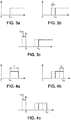
- Figures 3a to 3c and 4a to 4c illustrate audio signals emitted and captured by entities of the wireless audio system, according to a first embodiment of the invention.
- the internal latency of the sound recorder 103 is known so that the first internal latency (being an example of latency information) of the first receiver 101.1 can be completely determined based on the time reference of the test signal, based on the first audio record and based on the known internal latency of the sound recorder 103.
- detection of a rising edge of the first audio record is used to estimate the first internal latency of the first receiver.
- the wireless transmitter 100 transmits (at step 202, as explained above) a test signal being a square signal comprising at least a rising edge.
- the instant of the rising edge is considered as the time reference of the test signal, for illustrative purposes.
- the test signal can be a high frequency signal, so as to avoid the first audio record to be corrupted by ambient noise.
- a high frequency signal can represent any signal that is beyond the audible frequencies. For example, it can be any signal having a frequency higher than 4 kHz, and in practice, any signal having a frequency higher than 19 kHz.
- the wireless transmitter 100 transmits the test signal, which comprises a rising edge at an instant t 11 (the time reference of the test signal) after a local origin of time, which is shared with the sound recorder 103 as explained above (the sound recorder 103 and the wireless transmitter 100 are synchronized).
- the first receiver 101.1 plays the test signal, and the rising edge is played at an instant t 12 .
- Instant t 12 is delayed by the first internal latency L of the first receiver 101.1, which is to be estimated by the sound recorder 103.
- the first audio record acquired by the sound recorder 103 is illustrated on Figure 3c and the sound recorder 103 can detect the rising edge of the test signal at an instant t 13 .
- the rising edge can for example be detected by using a high-pass filter or by using a Fast Fourier Transform, FFT, and calculating the amplitude of the first audio record in the chosen frequency band. Detection of the rising edge can be performed "live" (upon acquisition of the first audio record) or can be delayed compared to the acquisition, by temporarily storing the first audio record in the sound recorder 103.
- t 13 is delayed because of the known internal latency of the sound recorder 103, referenced ⁇ SR on Figure 3c .
- detection of a falling edge of the first audio record is used to estimate the first internal latency of the first receiver.
- the test signal comprises a rising edge and a falling edge, and the duration between the rising edge and the falling edge is predetermined and known by the sound recorder 103.
- the test signal comprises a rising edge at an instant t 21 , which is considered as time reference of the test signal.
- the amplitude of the test signal is then maintained over a duration T and then comprises a falling edge.
- the first receiver 101.1 plays the test signal (which is a sound having a duration of T) and the falling edge is played at a time t 22 .
- t 22 is delayed by the first internal latency L of the first receiver 101.1, which is to be estimated by the sound recorder 103.
- the first audio record acquired by the sound recorder 103 is illustrated on Figure 4c .
- the sound recorder 103 can detect the falling edge on the test signal at an instant t 23 .
- the detection of the falling edge can also be performed using a high-pass filter or by using a Fast Fourier Transform, as explained above.
- the second internal latency can also be determined using a similar method as the one used for the first receiver 101.1. More generally, all the internal latencies of all the receivers of the wireless audio system can be determined.
- the internal latency of the sound recorder 103 is not known so that the latency information is a difference of internal latencies between the first receiver 101.1 and the second receiver 101.2, the difference being determined by using two receivers as explained hereafter. Simultaneously, the second internal latency of the second receiver 101.2 can be determined.
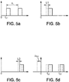
- the second embodiment is illustrated with reference to figures 5a to 5d .
- the wireless transmitter 100 generates a first test signal and a second test signal. Both test signals can be the same signals (for example a square signal having a rising edge and a falling edge and a given duration). However, the test signals may also be different.
- the first test signal is transmitted to the first receiver 101.1, then, after a given time gap ⁇ t (which is considered as the time reference of the test signals), the second test signal is transmitted to the second receiver 101.2, as illustrated on figure 5a .
- the first test signal and the second test signal can be high frequency signals, so as to avoid corrupting the record by the sound recorder 103 with ambient noise.
- the first receiver 101.1 plays the first test signal, after receiving it and after an internal latency referenced L 1 due to internal processing.
- the second receiver 101.2 plays the second test signal, after receiving it and after an internal latency referenced L 2 due to internal processing.
- the two receivers are different (from different manufacturers, from the same manufacturers but of different types or different versions), it is likely that their internal latencies L 1 and L 2 are different.
- the first audio record acquired by the sound recorder 103.
- the first audio record comprises both the first test signal played by the first receiver 101.1 and the second test signal played by the second receiver 101.2.
- the rising edge of the played first test signal can be detected, at instant t 32 and the rising edge of the played second test signal can be detected at instant t 33 .
- the rising edges can be determined as already explained above. Alternatively, and as already explained, the detection of rising edges can be replaced with detection of falling edges without departing from the scope of the invention.
- the latency information is then the difference ⁇ L , which can be advantageously used by the source device 104 to adapt transmission of audio data to the receivers 101.1 and 101.2. For example, if ⁇ L is such that the first internal latency of the first receiver 101.1 is less than the second internal latency of the second receiver 101.2, then audio data sent to the first receiver 101.1 can be delayed by ⁇ L to ensure synchronization between the receivers 101.1 and 101.2.
- the advantage of the second embodiment, compared to the first embodiment, is that it does not require knowing the internal latency ⁇ SR of the sound recorder 103, which is sometimes hard to determine with accuracy.
- the method according to the invention can be repeated so as to acquire more than the first audio record (second audio record, third audio record, and so on).
- a global latency information can be obtained based on the series of latency information that are obtained, for example using an average calculation or by eliminating the extreme values.
- the method according to the invention can be performed after clock synchronization between the wireless transmitter and the at least one receiver is stabilized.
- the slave devices generally synchronize their respective internal clocks with a Bluetooth clock of the master device.
- the rendering delay which is a delay between transmission of data by the wireless transmitter 100 and outputting of audio data by the receiver, may vary, thereby decreasing the accuracy in the latency information. It is therefore preferable to perform the method according to the invention after the synchronization is stabilized.
- the duration required for stabilization may vary depending on the receivers.
- the transmission of the test signal can be delayed by a predetermined delay of k seconds, for example 40 seconds. This can be for example the delay between the origin of time in the transmitter and the rising edge of the test signal.
- Figure 6 shows a sound recorder 103 according to some embodiments of the invention.
- the sound recorder 103 comprises a random access memory 604 and a processor 602 that can store instructions for performing the steps described with reference to figure 2 , in particular steps 204 to 206.
- the sound recorder 103 may also comprise a database 603 for storing data resulting from the method according to the invention, in particular for storing the audio records and/or the latency information that have been determined based on the audio records.
- the sound recorder 103 comprises an input interface 601, which is preferably a microphone, to acquire the audio records from the receivers 101.1.
- the sound recorder 103 also comprises an output interface 605, for transmitting the latency information to the wireless transmitter 101.
- Figure 7 shows a wireless transmitter 100 according to some embodiments of the invention.
- the wireless transmitter 100 comprises a random access memory 704 and a processor 702 that can store instructions for performing the steps described with reference to figure 2 , in particular steps 201, 202 and 207.
- the wireless transmitter 100 may also comprise a database 703 for storing data resulting from the method according to the invention, in particular for storing the latency information received from the sound recorder 103, so that the processor 702 can adapt the transmission of audio data to the receivers 101.1 and 101.2 based on the latency information.
- a database 703 for storing data resulting from the method according to the invention, in particular for storing the latency information received from the sound recorder 103, so that the processor 702 can adapt the transmission of audio data to the receivers 101.1 and 101.2 based on the latency information.
- the wireless transmitter 100 comprises an input interface 701, which is arranged to receive the latency information from the sound recorder 103.
- the wireless transmitter also comprises an output interface 605, for transmitting audio data to the receivers 101.1 and 101.2 via the channels 105.1 and 105.2.
- a method and a sound recorder that enable to determine latency information that is useful for synchronizing audio data to be transmitter to wireless receivers.
- This can be used for static synchronization (i.e. assuming that no audio data packet is lost in the system) of a wireless audio system comprising one, or preferably several, wireless receivers such as loudspeakers or headphones.
- the static synchronization method is described in detail in the French patent application filed under number FR1657050 , and is not further described in the present application as these subsequent steps are outside the scope of the application.
- the microphone of a Smartphone (which can be the source device 104) can be used as a sound recorder.
- a new receiver is connected to the source device 104 according to the invention (assuming there is already another connected receiver), there are two possible cases:
- the internal latency of the new receiver can be determined based on the difference of the latencies obtained from the sound recorder 103.
- the internal latency of the new receiver can then be stored in a database of the source device 104 and can be uploaded to a remote server so that other source devices of other users can access to the internal latency of the new receiver, thereby avoiding to perform similar operations in the other source devices.
- the difference ⁇ L can be stored in the database, until the internal latency of one of the receivers is known.
- the internal latency of the other receiver can then be deduced from the difference ⁇ L , or until a third receiver, which internal latency is known, is connected to the source device, so as to repeat the method according to the invention with the third receiver and the new receiver.
- the present invention can also be embedded in a computer program product, which comprises all the features enabling the implementation of the methods described herein, and which, when loaded in an information processing system, causes the information processing system.
- Computer program means or computer program in the present context mean any expression, in any language, code or notation, of a set of instructions intended to cause a system having an information processing capability to perform a particular function either directly or after the conversion to another language.
- Such a computer program can be stored on a computer or machine readable medium allowing data, instructions, messages or message packets, and other machine readable information to be read from the medium.
- the computer or machine readable medium may include non-volatile memory, such as ROM, Flash memory, Disk drive memory, CD-ROM, and other permanent storage.
- a computer or machine readable medium may include, for example, volatile storage such as RAM, buffers, cache memory, and network circuits.
- the computer or machine readable medium may comprise computer or machine readable information in a transitory state medium such as a network link and/or a network interface, including a wired network or a wireless network, that allow a device to read such computer or machine readable information.
Landscapes
- Engineering & Computer Science (AREA)
- Signal Processing (AREA)
- Computer Networks & Wireless Communication (AREA)
- Environmental & Geological Engineering (AREA)
- Health & Medical Sciences (AREA)
- General Health & Medical Sciences (AREA)
- Otolaryngology (AREA)
- Physics & Mathematics (AREA)
- Acoustics & Sound (AREA)
- Multimedia (AREA)
- Circuit For Audible Band Transducer (AREA)
Priority Applications (3)
| Application Number | Priority Date | Filing Date | Title |
|---|---|---|---|
| EP17305537.7A EP3402220A1 (fr) | 2017-05-11 | 2017-05-11 | Obtention d'information de latence dans un système audio sans fil |
| PCT/EP2018/060496 WO2018206287A1 (fr) | 2017-05-11 | 2018-04-24 | Obtention d'informations de latence dans un système audio sans fil |
| US16/610,753 US11089496B2 (en) | 2017-05-11 | 2018-04-24 | Obtention of latency information in a wireless audio system |
Applications Claiming Priority (1)
| Application Number | Priority Date | Filing Date | Title |
|---|---|---|---|
| EP17305537.7A EP3402220A1 (fr) | 2017-05-11 | 2017-05-11 | Obtention d'information de latence dans un système audio sans fil |
Publications (1)
| Publication Number | Publication Date |
|---|---|
| EP3402220A1 true EP3402220A1 (fr) | 2018-11-14 |
Family
ID=58772514
Family Applications (1)
| Application Number | Title | Priority Date | Filing Date |
|---|---|---|---|
| EP17305537.7A Withdrawn EP3402220A1 (fr) | 2017-05-11 | 2017-05-11 | Obtention d'information de latence dans un système audio sans fil |
Country Status (3)
| Country | Link |
|---|---|
| US (1) | US11089496B2 (fr) |
| EP (1) | EP3402220A1 (fr) |
| WO (1) | WO2018206287A1 (fr) |
Cited By (4)
| Publication number | Priority date | Publication date | Assignee | Title |
|---|---|---|---|---|
| CN110365555A (zh) * | 2019-08-08 | 2019-10-22 | 广州虎牙科技有限公司 | 音频延时测试方法、装置、电子设备及可读存储介质 |
| CN110505563A (zh) * | 2019-09-11 | 2019-11-26 | 歌尔科技有限公司 | 无线耳机的同步检测方法、装置及无线耳机和存储介质 |
| WO2020163476A1 (fr) * | 2019-02-06 | 2020-08-13 | Bose Corporation | Négociation de latence dans un réseau hétérogène de haut-parleurs synchronisés |
| FR3111497A1 (fr) * | 2020-06-12 | 2021-12-17 | Orange | Procédé de gestion de la restitution d’un contenu multimédia sur des dispositifs de restitution. |
Families Citing this family (1)
| Publication number | Priority date | Publication date | Assignee | Title |
|---|---|---|---|---|
| CN114390587B (zh) * | 2021-12-21 | 2025-08-19 | Oppo广东移动通信有限公司 | 延时设置方法、装置、存储介质及无线设备 |
Citations (4)
| Publication number | Priority date | Publication date | Assignee | Title |
|---|---|---|---|---|
| US20120288124A1 (en) * | 2011-05-09 | 2012-11-15 | Dts, Inc. | Room characterization and correction for multi-channel audio |
| US20150195666A1 (en) * | 2014-01-07 | 2015-07-09 | Howard Massey | Device, Method and Software for Measuring Distance To A Sound Generator By Using An Audible Impulse Signal. |
| US20150228282A1 (en) * | 2012-09-06 | 2015-08-13 | Sagemcom Broadband Sas | Device and method for supplying a reference audio signal to an acoustic processing unit |
| US9165547B2 (en) * | 2012-09-17 | 2015-10-20 | Blackberry Limited | Localization of a wireless user equipment (UE) device based on audio masking |
Family Cites Families (1)
| Publication number | Priority date | Publication date | Assignee | Title |
|---|---|---|---|---|
| EP3214858A1 (fr) * | 2016-03-03 | 2017-09-06 | Thomson Licensing | Appareil et procédé de détermination d'un retard et paramètres de gain pour étalonnage d'un système audio à multiples canaux |
-
2017
- 2017-05-11 EP EP17305537.7A patent/EP3402220A1/fr not_active Withdrawn
-
2018
- 2018-04-24 WO PCT/EP2018/060496 patent/WO2018206287A1/fr not_active Ceased
- 2018-04-24 US US16/610,753 patent/US11089496B2/en active Active
Patent Citations (4)
| Publication number | Priority date | Publication date | Assignee | Title |
|---|---|---|---|---|
| US20120288124A1 (en) * | 2011-05-09 | 2012-11-15 | Dts, Inc. | Room characterization and correction for multi-channel audio |
| US20150228282A1 (en) * | 2012-09-06 | 2015-08-13 | Sagemcom Broadband Sas | Device and method for supplying a reference audio signal to an acoustic processing unit |
| US9165547B2 (en) * | 2012-09-17 | 2015-10-20 | Blackberry Limited | Localization of a wireless user equipment (UE) device based on audio masking |
| US20150195666A1 (en) * | 2014-01-07 | 2015-07-09 | Howard Massey | Device, Method and Software for Measuring Distance To A Sound Generator By Using An Audible Impulse Signal. |
Non-Patent Citations (2)
| Title |
|---|
| ANONYMOUS: "Detect or Approximate Bluetooth Latency on Android (Audio Playback) - Stack Overflow", 22 April 2016 (2016-04-22), XP055404225, Retrieved from the Internet <URL:https://stackoverflow.com/questions/35139179/detect-or-approximate-bluetooth-latency-on-android-audio-playback> [retrieved on 20170906] * |
| JAMES COVERT: "This app is making Bluetooth speakers even better", NEW YORK POST, 15 December 2016 (2016-12-15), pages 1 - 1, XP055404157, Retrieved from the Internet <URL:http://nypost.com/2016/12/15/this-app-is-making-bluetooth-speakers-even-better/> [retrieved on 20170906] * |
Cited By (9)
| Publication number | Priority date | Publication date | Assignee | Title |
|---|---|---|---|---|
| WO2020163476A1 (fr) * | 2019-02-06 | 2020-08-13 | Bose Corporation | Négociation de latence dans un réseau hétérogène de haut-parleurs synchronisés |
| US10880594B2 (en) | 2019-02-06 | 2020-12-29 | Bose Corporation | Latency negotiation in a heterogeneous network of synchronized speakers |
| US12120376B2 (en) | 2019-02-06 | 2024-10-15 | Bose Corporation | Latency negotiation in a heterogeneous network of synchronized speakers |
| CN110365555A (zh) * | 2019-08-08 | 2019-10-22 | 广州虎牙科技有限公司 | 音频延时测试方法、装置、电子设备及可读存储介质 |
| CN110365555B (zh) * | 2019-08-08 | 2021-12-10 | 广州虎牙科技有限公司 | 音频延时测试方法、装置、电子设备及可读存储介质 |
| CN110505563A (zh) * | 2019-09-11 | 2019-11-26 | 歌尔科技有限公司 | 无线耳机的同步检测方法、装置及无线耳机和存储介质 |
| CN110505563B (zh) * | 2019-09-11 | 2020-12-01 | 歌尔科技有限公司 | 无线耳机的同步检测方法、装置及无线耳机和存储介质 |
| US12075216B2 (en) | 2019-09-11 | 2024-08-27 | Goertek Inc. | Wireless earphone synchronization detection method, apparatus, wireless earphones and storage medium |
| FR3111497A1 (fr) * | 2020-06-12 | 2021-12-17 | Orange | Procédé de gestion de la restitution d’un contenu multimédia sur des dispositifs de restitution. |
Also Published As
| Publication number | Publication date |
|---|---|
| US20200322818A1 (en) | 2020-10-08 |
| WO2018206287A1 (fr) | 2018-11-15 |
| US11089496B2 (en) | 2021-08-10 |
Similar Documents
| Publication | Publication Date | Title |
|---|---|---|
| JP7426448B2 (ja) | 接続されたマルチメディアデバイスの制御 | |
| US11375312B2 (en) | Method, device, loudspeaker equipment and wireless headset for playing audio synchronously | |
| CN115551068B (zh) | 蓝牙媒体设备时间同步的方法和设备 | |
| US11089496B2 (en) | Obtention of latency information in a wireless audio system | |
| JP6509116B2 (ja) | オーディオ転送デバイス及び対応する方法 | |
| US11800284B2 (en) | Bluetooth device and method for controlling a plurality of wireless audio devices with a Bluetooth device | |
| US11277691B2 (en) | Controlling dual-mode Bluetooth low energy multimedia devices | |
| JP2019532576A (ja) | オーディオとビデオのマルチモード同期レンダリング | |
| CN116671114B (zh) | 多媒体回放同步 | |
| US11876847B2 (en) | System and method for synchronizing networked rendering devices | |
| JP2019531669A (ja) | Bluetoothマルチメディアデバイスの制御 | |
| KR20170134451A (ko) | 멀티 계층 타이밍 동기화 프레임워크 | |
| US11736883B2 (en) | Audio data transmitting/receiving method using Bluetooth low power in wireless communication system, and apparatus therefor | |
| KR101582472B1 (ko) | 무선 오디오 재생 방법 및 이를 실행하는 오디오 소스 | |
| CN116249076A (zh) | 基于多播系统的音频同步方法、装置及可读存储介质 |
Legal Events
| Date | Code | Title | Description |
|---|---|---|---|
| PUAI | Public reference made under article 153(3) epc to a published international application that has entered the european phase |
Free format text: ORIGINAL CODE: 0009012 |
|
| STAA | Information on the status of an ep patent application or granted ep patent |
Free format text: STATUS: THE APPLICATION HAS BEEN PUBLISHED |
|
| AK | Designated contracting states |
Kind code of ref document: A1 Designated state(s): AL AT BE BG CH CY CZ DE DK EE ES FI FR GB GR HR HU IE IS IT LI LT LU LV MC MK MT NL NO PL PT RO RS SE SI SK SM TR |
|
| AX | Request for extension of the european patent |
Extension state: BA ME |
|
| STAA | Information on the status of an ep patent application or granted ep patent |
Free format text: STATUS: REQUEST FOR EXAMINATION WAS MADE |
|
| 17P | Request for examination filed |
Effective date: 20190506 |
|
| RBV | Designated contracting states (corrected) |
Designated state(s): AL AT BE BG CH CY CZ DE DK EE ES FI FR GB GR HR HU IE IS IT LI LT LU LV MC MK MT NL NO PL PT RO RS SE SI SK SM TR |
|
| STAA | Information on the status of an ep patent application or granted ep patent |
Free format text: STATUS: EXAMINATION IS IN PROGRESS |
|
| 17Q | First examination report despatched |
Effective date: 20190913 |
|
| STAA | Information on the status of an ep patent application or granted ep patent |
Free format text: STATUS: THE APPLICATION IS DEEMED TO BE WITHDRAWN |
|
| 18D | Application deemed to be withdrawn |
Effective date: 20200603 |
|
| P01 | Opt-out of the competence of the unified patent court (upc) registered |
Effective date: 20230520 |