EP3402255A1 - Procédé de vérification de puissance d'émission, équipement utilisateur et station de base - Google Patents
Procédé de vérification de puissance d'émission, équipement utilisateur et station de base Download PDFInfo
- Publication number
- EP3402255A1 EP3402255A1 EP16888650.5A EP16888650A EP3402255A1 EP 3402255 A1 EP3402255 A1 EP 3402255A1 EP 16888650 A EP16888650 A EP 16888650A EP 3402255 A1 EP3402255 A1 EP 3402255A1
- Authority
- EP
- European Patent Office
- Prior art keywords
- transmit power
- power
- link
- value
- control information
- Prior art date
- Legal status (The legal status is an assumption and is not a legal conclusion. Google has not performed a legal analysis and makes no representation as to the accuracy of the status listed.)
- Granted
Links
Images




Classifications
-
- H—ELECTRICITY
- H04—ELECTRIC COMMUNICATION TECHNIQUE
- H04W—WIRELESS COMMUNICATION NETWORKS
- H04W52/00—Power management, e.g. Transmission Power Control [TPC] or power classes
- H04W52/04—Transmission power control [TPC]
- H04W52/54—Signalisation aspects of the TPC commands, e.g. frame structure
-
- H—ELECTRICITY
- H04—ELECTRIC COMMUNICATION TECHNIQUE
- H04W—WIRELESS COMMUNICATION NETWORKS
- H04W4/00—Services specially adapted for wireless communication networks; Facilities therefor
- H04W4/30—Services specially adapted for particular environments, situations or purposes
- H04W4/40—Services specially adapted for particular environments, situations or purposes for vehicles, e.g. vehicle-to-pedestrians [V2P]
- H04W4/46—Services specially adapted for particular environments, situations or purposes for vehicles, e.g. vehicle-to-pedestrians [V2P] for vehicle-to-vehicle communication [V2V]
-
- H—ELECTRICITY
- H04—ELECTRIC COMMUNICATION TECHNIQUE
- H04W—WIRELESS COMMUNICATION NETWORKS
- H04W52/00—Power management, e.g. Transmission Power Control [TPC] or power classes
- H04W52/04—Transmission power control [TPC]
- H04W52/18—TPC being performed according to specific parameters
- H04W52/28—TPC being performed according to specific parameters using user profile, e.g. mobile speed, priority or network state, e.g. standby, idle or non-transmission
- H04W52/286—TPC being performed according to specific parameters using user profile, e.g. mobile speed, priority or network state, e.g. standby, idle or non-transmission during data packet transmission, e.g. high speed packet access [HSPA]
-
- H—ELECTRICITY
- H04—ELECTRIC COMMUNICATION TECHNIQUE
- H04W—WIRELESS COMMUNICATION NETWORKS
- H04W52/00—Power management, e.g. Transmission Power Control [TPC] or power classes
- H04W52/04—Transmission power control [TPC]
- H04W52/30—Transmission power control [TPC] using constraints in the total amount of available transmission power
- H04W52/32—TPC of broadcast or control channels
- H04W52/325—Power control of control or pilot channels
-
- H—ELECTRICITY
- H04—ELECTRIC COMMUNICATION TECHNIQUE
- H04W—WIRELESS COMMUNICATION NETWORKS
- H04W52/00—Power management, e.g. Transmission Power Control [TPC] or power classes
- H04W52/04—Transmission power control [TPC]
- H04W52/30—Transmission power control [TPC] using constraints in the total amount of available transmission power
- H04W52/34—TPC management, i.e. sharing limited amount of power among users or channels or data types, e.g. cell loading
- H04W52/346—TPC management, i.e. sharing limited amount of power among users or channels or data types, e.g. cell loading distributing total power among users or channels
-
- H—ELECTRICITY
- H04—ELECTRIC COMMUNICATION TECHNIQUE
- H04W—WIRELESS COMMUNICATION NETWORKS
- H04W52/00—Power management, e.g. Transmission Power Control [TPC] or power classes
- H04W52/04—Transmission power control [TPC]
- H04W52/38—TPC being performed in particular situations
- H04W52/383—TPC being performed in particular situations power control in peer-to-peer links
-
- H—ELECTRICITY
- H04—ELECTRIC COMMUNICATION TECHNIQUE
- H04W—WIRELESS COMMUNICATION NETWORKS
- H04W72/00—Local resource management
- H04W72/04—Wireless resource allocation
- H04W72/044—Wireless resource allocation based on the type of the allocated resource
- H04W72/0473—Wireless resource allocation based on the type of the allocated resource the resource being transmission power
-
- H—ELECTRICITY
- H04—ELECTRIC COMMUNICATION TECHNIQUE
- H04W—WIRELESS COMMUNICATION NETWORKS
- H04W72/00—Local resource management
- H04W72/20—Control channels or signalling for resource management
-
- H—ELECTRICITY
- H04—ELECTRIC COMMUNICATION TECHNIQUE
- H04W—WIRELESS COMMUNICATION NETWORKS
- H04W52/00—Power management, e.g. Transmission Power Control [TPC] or power classes
- H04W52/04—Transmission power control [TPC]
- H04W52/06—TPC algorithms
- H04W52/08—Closed loop power control
-
- H—ELECTRICITY
- H04—ELECTRIC COMMUNICATION TECHNIQUE
- H04W—WIRELESS COMMUNICATION NETWORKS
- H04W52/00—Power management, e.g. Transmission Power Control [TPC] or power classes
- H04W52/04—Transmission power control [TPC]
- H04W52/06—TPC algorithms
- H04W52/10—Open loop power control
-
- H—ELECTRICITY
- H04—ELECTRIC COMMUNICATION TECHNIQUE
- H04W—WIRELESS COMMUNICATION NETWORKS
- H04W52/00—Power management, e.g. Transmission Power Control [TPC] or power classes
- H04W52/04—Transmission power control [TPC]
- H04W52/18—TPC being performed according to specific parameters
- H04W52/24—TPC being performed according to specific parameters using SIR [Signal to Interference Ratio] or other wireless path parameters
- H04W52/242—TPC being performed according to specific parameters using SIR [Signal to Interference Ratio] or other wireless path parameters taking into account path loss
-
- H—ELECTRICITY
- H04—ELECTRIC COMMUNICATION TECHNIQUE
- H04W—WIRELESS COMMUNICATION NETWORKS
- H04W52/00—Power management, e.g. Transmission Power Control [TPC] or power classes
- H04W52/04—Transmission power control [TPC]
- H04W52/30—Transmission power control [TPC] using constraints in the total amount of available transmission power
- H04W52/36—Transmission power control [TPC] using constraints in the total amount of available transmission power with a discrete range or set of values, e.g. step size, ramping or offsets
- H04W52/367—Power values between minimum and maximum limits, e.g. dynamic range
Definitions
- Embodiments of the present invention relate to the communications field, and more specifically, to a transmit power determining method, user equipment, and a base station.
- V2X vehicle to everything
- V2V vehicle to Vehicle
- V2I vehicle to Infrastructure
- V2P vehicle to pedestrian
- P2V pedestrian to vehicle
- An essential problem of V2X communication is how to implement efficient communication between a vehicle and various devices in various complex environments, especially how to improve communication reliability and reduce a communication delay.
- the 3rd Generation Partnership Project (3rd Generation Partnership Project, 3GPP) proposes that research on the Internet of Vehicles be performed according to an existing device to device (Device to Device, D2D) protocol.
- D2D Device to Device
- control information and data information for V2X communication are based on time division multiplexing. This causes an additional delay.
- control information and data information be configured in a same subframe to reduce a delay.
- Embodiments of the present invention provide a transmit power determining method, to effectively allocate transmit powers for control information and data.
- a transmit power determining method including:
- the transmit power indication information includes first indication information of a first maximum transmit power of the UE.
- the first transmit power of the control information and the second transmit power of the data can be determined based on the foregoing embodiment of the present invention. This can resolve a prior-art problem that UE does not know how to properly determine transmit powers of control information and data.
- the first indication information includes one piece of control information instructing to use maximum transmit powers for both the control information and the data, or the first indication information includes two independent pieces of control information respectively instructing to use maximum transmit powers for the control information and the data.
- control information and the data are carried in a same physical channel, or the control information is carried in a control channel of the first link, and the data is carried in a data channel of the first link.
- the determining a first transmit power of control information and a second transmit power of data based on the transmit power indication information includes: determining the first transmit power and the second transmit power, so that a sum of a linear value of the first transmit power and a linear value of the second transmit power is equal to the first maximum transmit power, and a ratio of the first transmit power to the second transmit power is equal to a first preset value.
- the determining a first transmit power of control information and a second transmit power of data based on the transmit power indication information includes: determining the first transmit power and the second transmit power, so that a sum of a linear value of the first transmit power and a linear value of the second transmit power is equal to the first maximum transmit power, and a difference between the first transmit power and the second transmit power is equal to a second preset value.
- the determining a first transmit power of control information and a second transmit power of data based on the transmit power indication information includes: determining the first transmit power and the second transmit power, so that a sum of a linear value of the first transmit power and a linear value of the second transmit power is equal to the first maximum transmit power, and a difference between a transmit power on each PRB of the control information and a transmit power on each PRB of the data is equal to a third preset value.
- the determining a first transmit power of control information and a second transmit power of data based on the transmit power indication information includes: determining a first power of the control information and a second power of the data based on transmission bandwidth of the first link and a path loss value of a second link between the UE and a serving base station of the UE; and determining the first transmit power and the second transmit power based on the first power, the second power, and the first maximum transmit power.
- the first transmit power is equal to the first power and that the second transmit power is equal to the second power.
- the first transmit power is equal to the first power or equal to a smaller one of the first power and the first maximum transmit power and that the second transmit power is equal to a difference between the linear value of the first maximum transmit power and a linear value of the first transmit power.
- a sum of a linear value of the first power and a linear value of the second power is less than the first maximum transmit power, it is determined that the first transmit power is equal to a sum of the first power and a first value and that the second transmit power is equal to a sum of the second power and a second value, where a sum of a linear value of the first transmit power and a linear value of the second transmit power is equal to the first maximum transmit power, and the first value and the second value meet a predefined relationship.
- the transmit power indication information further includes second indication information of a second maximum transmit power of the control information.
- the determining a first transmit power of control information and a second transmit power of data based on the transmit power indication information includes: using the second maximum transmit power as the first transmit power; and determining that the second transmit power is a difference between a linear value of the first maximum transmit power and a linear value of the first transmit power.
- the determining a first transmit power of control information and a second transmit power of data based on the transmit power indication information includes: determining a first power of the control information based on transmission bandwidth of the first link and a path loss value of a second link between the UE and a serving base station of the UE; using a smaller one of the first power and the second maximum transmit power as the first transmit power; and determining that the second transmit power is a difference between a linear value of the first maximum transmit power and a linear value of the first transmit power.
- the transmit power indication information further includes second indication information of a second maximum transmit power of the control information
- the transmit power indication information further includes third indication information of a third maximum transmit power of the data.
- the determining a first transmit power of control information and a second transmit power of data based on the transmit power indication information includes: determining a second power of the data based on transmission bandwidth of the first link and a path loss value of a second link between the UE and a serving base station of the UE; using the second maximum transmit power as the first transmit power, or using a smaller one of a first power and the second maximum transmit power as the first transmit power, where the first power is of the control information and is determined based on the transmission bandwidth and the path loss value; and using a smallest one of the second power, the third maximum transmit power, and a difference between a linear value of the first maximum transmit power and a linear value of the first transmit power as the second transmit power.
- the determining a first transmit power of control information and a second transmit power of data based on the transmit power indication information includes: determining a first power of the control information based on transmission bandwidth of the first link and a path loss value of a second link between the UE and a serving base station of the UE; using the third maximum transmit power as the second transmit power, or using a smaller one of a second power of the data and the third maximum transmit power as the second transmit power, where the second power is determined based on the transmission bandwidth and the path loss value; and using a smallest one of the first power, the second maximum transmit power, and a difference between a linear value of the first maximum transmit power and a linear value of the second transmit power as the first transmit power.
- the method further includes: transmitting the control information and/or the data a plurality of times, where in at least one of the plurality of transmissions, the control information and the data are in a same subframe, where a quantity of the plurality of transmissions of the control information is or is not equal to a quantity of the plurality of transmissions of the data.
- transmission of the control information includes a first part transmission of the control information and a second part transmission of the control information
- transmission of the data includes a first part transmission of the data and a second part transmission of the data
- the first part transmission of the control information and the first part transmission of the data are performed in a same subframe
- the second part transmission of the control information and the second part transmission of the data are performed in different subframes
- the sending the control information on the first link at the first transmit power, and sending the data on the first link at the second transmit power includes: performing the first part transmission of the control information on the first link at the first transmit power, and performing the first part transmission of the data on the first link at the second transmit power; and performing the second part transmission of the control information on the first link at a third transmit power, and performing the second part transmission of the data on the first link at a fourth transmit power, where neither of the third transmit power nor the fourth transmit power is greater than the first maximum transmit power.
- user equipment including:
- the user equipment in the second aspect can implement the transmit power determining method performed by the UE in the method in the first aspect.
- user equipment including:
- the user equipment in the third aspect can implement the transmit power determining method performed by the UE in the method in the first aspect.
- a computer readable storage medium where a program is stored in the computer readable storage medium, and the program enables user equipment to perform the transmit power determining method according to any one of the first aspect and the implementations of the first aspect.
- a method for determining a first-link transmit power including:
- the receiving, by first UE, first indication information includes: receiving, by the first UE, the first indication information from the second UE or a base station.
- the first UE may determine the first-link transmit power based on the first indication information. This can prevent communication on a cellular link of the base station from being interfered with by data transmission between UEs on the first link, and also can ensure efficiency of communication on the first link and communication on a second link.
- the determining, by the first UE, the first-link transmit power based on the first indication information includes: using a smaller one of a second maximum transmit power of the first UE and the first maximum transmit power as the first-link transmit power.
- the determining, by the first UE, the first-link transmit power based on the first indication information includes: determining a first power based on transmission bandwidth of the first link and a path loss value of the first link; and using a smaller one of the first maximum transmit power and the first power as the first-link transmit power; or using a smallest one of a second maximum transmit power of the first UE, the first maximum transmit power, and the first power as the first-link transmit power.
- the method further includes: receiving indication information used to indicate an identity ID of a sequence used by the first UE, where the ID of the sequence used by the first UE has a same value as that of an ID of a sequence used by one or more other UEs that communicate with the second UE, or the ID of the sequence used by the first UE has a value different from that of an ID of a sequence used by one or more other UEs that communicate with the second UE, and the ID of the sequence used by the first UE is a value associated with the second UE.
- the determining, by the first UE, the first-link transmit power based on the first indication information includes: using a smaller one of a maximum transmit power of the first UE and the first maximum transmit power as a first transmit power; sending the sequence at the first transmit power; receiving adjustment indication information sent by the base station, where the adjustment indication information is generated by the base station based on the sequence; and adjusting the first transmit power based on the adjustment indication information to determine the first-link transmit power.
- the sending the sequence includes: sending the sequence on a second link between the first UE and the base station; or sending the sequence on the first link.
- the method before the determining the first-link transmit power, the method further includes: receiving, by the first UE, second indication information sent by the second UE or the base station, where the second indication information includes indication information of a third maximum transmit power of the first UE.
- the determining the first-link transmit power includes: using a smallest one of a second maximum transmit power of the first UE, the first maximum transmit power, and the third maximum transmit power as the first-link transmit power; using a smaller one of a second maximum transmit power of the first UE and the third maximum transmit power as the first-link transmit power; or using a smaller one of the first maximum transmit power and the third maximum transmit power as the first-link transmit power.
- a method for determining a first-link transmit power including:
- An ID of a sequence used by the first UE has a same value as that of an ID of a sequence used by one or more other UEs that communicate with the second UE, or an ID of a sequence used by the first UE has a value different from that of an ID of a sequence used by one or more other UEs that communicate with the second UE, and the ID of the sequence used by the first UE is a value associated with the second UE.
- the determining, based on the first power, power adjustment information corresponding to the first UE includes: determining a value relationship between the first power and a specific threshold of the base station, and determining the power adjustment information based on the value relationship.
- user equipment is provided, where the user equipment is first UE and includes:
- the user equipment in the seventh aspect can implement the method for determining a first-link transmit power performed by the first UE in the method in the fifth aspect.
- user equipment including:
- the user equipment in the eighth aspect can implement the method for determining a first-link transmit power performed by the first UE in the method in the fifth aspect.
- a computer readable storage medium where a program is stored in the computer readable storage medium, and the program enables user equipment to perform the method for determining a first-link transmit power according to any one of the fifth aspect and the implementations of the fifth aspect.
- a base station including:
- the base station in the tenth aspect can implement the method for determining a first-link transmit power performed by the base station in the method in the sixth aspect.
- a base station including:
- the base station in the eleventh aspect can implement the method for determining a first-link transmit power performed by the base station in the method in the sixth aspect.
- a computer readable storage medium where a program is stored in the computer readable storage medium, and the program enables a base station to perform the method for determining a first-link transmit power according to either the sixth aspect and the implementation of the sixth aspect.
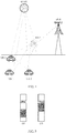
- FIG. 1 is a schematic diagram of a V2V communication scenario in an embodiment of the present invention.
- FIG. 1 shows a schematic diagram of a scenario in which four vehicles communicate with each other on lanes.
- assisted driving and autonomous driving can be implemented through wireless communication among a plurality of on-board units (On-board Unit, OBU), thereby effectively increasing traffic efficiency, avoiding a traffic accident, and reducing a driving risk.
- OBU On-board Unit
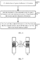
- FIG. 2 and FIG. 3 are schematic diagrams of application scenarios in an embodiment of the present invention.
- UE 20 can directly communicate with a base station 10, and the UE 20 may be referred to as relay (relay) UE.
- UE 30 cannot necessarily directly communicate with the base station 10, but the UE 30 can communicate with the UE 20. Therefore, the UE 30 can implement communication with the base station 10 by using the UE 20.
- the UE 30 may be referred to as remote (remote) UE.
- a communication distance between the UE 20 and the UE 30 with which the UE 20 can communicate is relatively short, for example, approximately 10 meters (m).
- a communication distance between the UE 20 and the UE 30 with which the UE 20 can communicate is relatively long, for example, approximately 100 m to 1000 m.
- FIG. 4 shows a schematic diagram of an actual application scenario in an embodiment of the present invention.
- An evolved NodeB (evolved NodeB, eNB) in FIG. 4 is equivalent to the base station 10 in FIG. 2 and FIG. 3 .
- a roadside unit (Road Side Unit, RSU), and UE 1, UE 2, and UE 3 in FIG. 4 may respectively be the UE 20 and the UEs 30 in FIG. 2 and FIG. 3 .
- the RSU is the UE 20, and can directly communicate with the eNB;
- the UE 1, the UE 2, and the UE 3 are the UEs 30, and can communicate with the eNB by using the RSU.
- FIG. 4 further shows a global navigation satellite system (Global Navigation Satellite System, GNSS) that may be configured to provide location information and the like for another network element.
- GNSS Global Navigation Satellite System
- the RSU may be an on-board device or an eNB.
- the UE 1, the UE 2, and the UE 3 may be on-board devices, and the on-board devices may perform V2V communication with each other by using a sidelink (Sidelink).
- Sidelink Sidelink
- the on-board device moves at a high speed with vehicles. For example, when the UE 1 and the UE 2 move relatively, a relative movement speed is highest.
- the devices shown in FIG. 4 may use a spectrum used for a cellular link, or may use an intelligent transportation spectrum near 5.9 GHz. Technologies used by the devices to communicate with each other may be enhanced based on an LTE protocol or a D2D technology.
- the sidelink may be a communications link between UEs, and is referred to as a D2D link in D2D communication and is referred to as a PC5 link in a particular scenario.
- the sidelink is also referred to as a V2V link, a vehicle to infrastructure (Vehicle to Infrastructure, V2I) link, or a vehicle to pedestrian (Vehicle to Pedestrian, V2P) link, or the like.
- the sidelink may be used to send information in any of the following modes: a broadcast mode, a unicast mode, or a multicast mode.
- a spectrum used for a cellular link such as an uplink spectrum used for a cellular link, may be used for the sidelink.
- the UE may also be referred to as a terminal, and may include an OBU of a vehicle, an RSU or the like on a road side, or a mobile phone or the like used by a pedestrian.
- control information such as SA
- data Data
- SA and data are not adjacent in frequency domain in a same subframe
- SA and data are adjacent in frequency domain in a same subframe.
- locations of the SA and the data may be adjacent or not adjacent in frequency domain.
- the SA may be carried in an independent physical channel, such as a physical sidelink control channel (Physical Sidelink Control Channel, PSCCH), or the SA and the data may be carried in a same physical channel, such as a physical sidelink shared channel (Physical Sidelink Shared Channel, PSSCH).
- PSCCH Physical Sidelink Control Channel
- PSSCH Physical Sidelink shared channel
- SA is also referred to as a PSCCH channel, and is a channel used to transmit control information between UEs.
- the control information is used to indicate, to a receiver, parameter information used to transmit a data portion, such as a time-frequency resource location, a resource size, and a modulation and coding scheme (Modulation and Coding Scheme, MCS) value.
- MCS Modulation and Coding Scheme
- duration of one subframe is usually one millisecond (ms)
- duration of one subframe is not limited.
- duration of one subframe may be basic duration for one transmission, or may be preset duration.
- the duration of one subframe may be 1 ms, may be greater than 1 ms, for example, 2 ms or 10 ms, or may be less than 1 ms, for example, 0.625 ms, 0.125 ms, or 0.2 ms.
- Parallel transmission of SA and data is based on a multi-carrier system. Therefore, for a transmitter, a total available transmit power is fixed in one subframe, for example, does not exceed a maximum transmit power of UE.
- a base station instructs user equipment (User Equipment, UE) to use a maximum transmit power, if the SA is sent at the maximum transmit power, there is no transmit power available to the data, and vice versa.
- UE User Equipment
- a problem to be resolved in the embodiments of the present invention is how to determine a transmit power when UE performs transmission on a sidelink, and especially how to determine transmit powers of control information and data when a maximum transmit power is configured.
- First maximum transmit power is marked as P CMAX,c , P CMAX , P EMAX , or P EMAX,c , and has any of the following meanings:
- the first maximum transmit power may be a maximum transmit power configured or predefined by a base station and indicated by maximum transmit power indication information.
- a value of the first maximum transmit power herein may be a logarithmic value (whose unit may be dBm) or a linear value (whose unit may be mW), that is, may be a value corresponding to a single frequency-domain transmission resource (such as one PRB) or may be a value corresponding to entire transmission bandwidth.
- a power mentioned in subsequent embodiments of the present invention is of a logarithmic value or a linear value may be determined based on a unit of the power.
- First link indicates a communications link between UEs, and may be a D2D link, a V2X link, a sidelink (Sidelink), or the like.
- the first link may be a link between the UE 20 and the UE 30 in FIG. 2 or FIG. 3 , or may be a link between the RSU and the UE 3 in FIG. 4 .
- Communication on the first link may be based on any one of a unicast mode, a multicast mode, and a broadcast mode.
- Second link indicates a communications link between UE and a base station, and may be a cellular link.
- the second link may be a link between the UE 20/UE 30 and the base station 10 in FIG. 2 or FIG. 3 , or may be a link between the RSU and the eNB in FIG. 4 .
- Relay UE namely, relay UE, is UE that can directly communicate with a base station and can relay data from another UE to the base station.
- the relay UE may be the UE 20 in FIG. 2 or FIG. 3 , or may be the RSU in FIG. 4 .
- Remote UE is remote UE, and indicates UE that cannot necessarily directly communicate with a base station but can communicate with the base station by using relay UE.
- the remote UE may be the UE 30 in FIG. 2 or FIG. 3 , or may be the UE 1, the UE 2, or the UE 3 in FIG. 4 .
- FIG. 6 is a flowchart of a transmit power determining method in an embodiment of the present invention. This method is used to determine a first-link transmit power.
- Control information and data that are sent by UE may be in a same subframe.
- the control information and the data may be carried in different physical channels, the control channel is carried in a control channel (such as a PSCCH) of a first link, and the data is carried in a data channel (such as a PSSCH) of the first link.
- the control information and the data may be carried in a same physical channel.
- both the control information and the data are carried in a data channel (such as a PSSCH) of a first link.
- FIG. 7(a) and FIG. 7(b) are schematic diagrams of scenarios in which both control information (which is SA in FIG. 7 ) and data (data) are carried in a PSSCH.
- the method shown in FIG. 6 includes the following steps.
- the UE may obtain the transmit power indication information from a serving base station of the UE. For example, the UE may receive, on a second link, the transmit power indication information sent by the serving base station.
- the UE may be the UE 20 in FIG. 2 or FIG. 3 , the UE may be the RSU in FIG. 4 , the UE may be the UE 2, in FIG. 4 , that can communicate with the eNB, and so on. This is not limited in the present invention.
- the UE obtains the transmit power indication information of a first link.
- the transmit power indication information may include first indication information of a first maximum transmit power of the UE.
- the transmit power indication information may include one piece of control information instructing to use maximum transmit powers for both the control information and the data.
- the transmit power indication information is a 1-bit transmitter power control (Transmitter Power Control, TPC) command.
- TPC Transmitter Power Control
- the 1-bit TPC command "1" may be used to indicate that the maximum transmit powers are to be used for both the control information and the data of the UE, or the 1-bit TPC command "0" may be used to indicate that the maximum transmit powers are to be used for both the control information and the data of the UE. This is not limited in the present invention.
- the transmit power indication information may include two independent pieces of control information respectively instructing to use maximum transmit powers for the control information and the data.
- the transmit power indication information is a 2-bit TPC command.
- the 2-bit TPC command is "11", it indicates that the maximum transmit powers are to be used for both the control information and the data of the UE.
- the 2-bit TPC command is "10”, it indicates that a maximum transmit power is to be used for the control information of the UE, and a maximum transmit power may not be used for the data of the UE.
- the 2-bit TPC command of two bits is "01", it indicates that a maximum transmit power is to be used for the data of the UE, and a maximum transmit power may not be used for the control information of the UE.
- two independent fields may respectively indicate that a maximum transmit power is to be used for the control information and that a maximum transmit power is to be used for the data.
- one bit is used to indicate whether a maximum transmit power is to be used for the control information, and another bit is used to indicate whether a maximum transmit power is to be used for the data.
- At least one of indication information of maximum transmit powers may be indicated by using implicit information, for example, a status defined in an MCS field or a reserved bit in a time-domain or frequency-domain resource indication field.
- the serving base station may indicate a maximum transmit power (referred to as a second maximum transmit power) available to the control information of the UE, and/or indicate a maximum transmit power (referred to as a third maximum transmit power) available to the data of the UE.
- a second maximum transmit power referred to as a second maximum transmit power
- a third maximum transmit power referred to as a third maximum transmit power
- the second maximum transmit power is less than the first maximum transmit power
- the third maximum transmit power is less than the first maximum transmit power.
- the second maximum transmit power may be marked as P v1
- the third maximum transmit power may be marked as P v2 .
- the transmit power indication information includes second indication information of the second maximum transmit power of the control information. If the 2-bit TPC command is "11" or "01”, it may be considered that the transmit power indication information includes third indication information of the third maximum transmit power of the data. If the 2-bit TPC command is "11”, it may be considered that the transmit power indication information includes both second indication information of the second maximum transmit power of the control information and third indication information of the third maximum transmit power of the data.
- the UE may obtain configuration information from the serving base station.
- the configuration information may be sent by the serving base station in a broadcast mode by using control signaling.
- the configuration information may include a value of the second maximum transmit power and/or a value of the third maximum transmit power.
- the value of the second maximum transmit power and the value of the third maximum transmit power may be preconfigured by the serving base station of the UE.
- the value of the second maximum transmit power and the value of the third maximum transmit power may be indicated by the base station by using signaling such as radio resource control (Radio Resource Control, RRC) signaling or a system information block (System Information Block, SIB).
- RRC Radio Resource Control
- SIB System Information Block
- the value of the second maximum transmit power and the value of the third maximum transmit power may be predefined by the UE. For example, when the UE is not located in network coverage or is in a communications mode of non-network control, the UE may obtain the foregoing information by using information predefined in the UE.
- the value of the second maximum transmit power and the value of the third maximum transmit power may be agreed upon in advance in a communications protocol.
- the UE determines a first transmit power of control information and a second transmit power of data based on the transmit power indication information.
- the transmit power indication information in S101 includes the first indication information of the first maximum transmit power of the UE: optionally, in an embodiment, the first transmit power and the second transmit power may be determined, so that a sum of the first transmit power and the second transmit power is equal to the first maximum transmit power, and a ratio of the first transmit power to the second transmit power is equal to a first preset value.
- the sum of the first transmit power and the second transmit power may be a sum of a linear value of the first transmit power and a linear value of the second transmit power.
- a sum of the first transmit power and the second transmit power is equal to the first maximum transmit power means that the sum of the linear value of the first transmit power and the linear value of the second transmit power is equal to a linear value of the first maximum transmit power.
- the ratio of the first transmit power to the second transmit power may be a ratio of the linear value of the first transmit power to the linear value of the second transmit power.
- the first preset value may be predefined, for example, may be preconfigured in the UE.
- the first preset value may be agreed upon in advance in a communications protocol.
- an operation such as summation or subtraction between powers means calculation based on linear values (for example, a unit corresponding to linear values is milliwatt (mW)) of the powers.
- an operation such as summation or subtraction between powers needs to be performed after the corresponding powers are converted into linear values thereof. If an operation such as summation or subtraction between powers may be an operation between logarithmic values of the powers, corresponding description may be provided in a corresponding part of this specification.
- the first maximum transmit power may be allocated to the control information and the data based on the first preset value. If the first preset value is 1, the first maximum transmit power is equally allocated to the control information and the data.
- the first transmit power of the control information is 20 dBm (99.765 mW)
- the second transmit power of the data is 20 dBm (99.765 mW).
- the first transmit power and the second transmit power may be determined, so that a sum of the first transmit power and the second transmit power is equal to the first maximum transmit power, and a difference between the first transmit power and the second transmit power is equal to a second preset value.
- the difference between the first transmit power and the second transmit power may be a difference between a linear value of the first transmit power and a linear value of the second transmit power, or a difference between a logarithmic value of the first transmit power and a logarithmic value of the second transmit power.
- that a difference between the first transmit power and the second transmit power is equal to a second preset value means that a difference between the linear value of the first transmit power and the linear value of the second transmit power is equal to a linear value of the second preset value, or a difference between the logarithmic value of the first transmit power and the logarithmic value of the second transmit power is equal to a logarithmic value of the second preset value.
- the second preset value may be predefined, for example, may be preconfigured in the UE.
- the second preset value may be agreed upon in advance in a communications protocol.
- the first transmit power of the control information is 20.2 dBm (104.765 mW)
- the second transmit power of the data is 19.776 dBm (94.765 mW).
- the second preset value is 10 dBm
- the difference between the logarithmic value of the first transmit power and the logarithmic value of the second transmit power is equal to 10 dBm.
- the first transmit power and the second transmit power may be determined, so that a sum of the first transmit power and the second transmit power is equal to the first maximum transmit power, and a difference between a transmit power on each physical resource block (Physical Resource Block, PRB) of the control information and a transmit power on each PRB of the data is equal to a third preset value.
- PRB Physical Resource Block
- the difference between the transmit power on each PRB of the control information and the transmit power on each PRB of the data may be a difference between a linear value of the transmit power on each PRB of the control information and a linear value of the transmit power on each PRB of the data, or may be a difference between a logarithmic value of the transmit power on each PRB of the control information and a logarithmic value of the transmit power on each PRB of the data.
- a difference between a transmit power on each PRB of the control information and a transmit power on each PRB of the data is equal to a third preset value means that the difference between the linear value of the transmit power on each PRB of the control information and the linear value of the transmit power on each PRB of the data is equal to a linear value the third preset value, or the difference between the logarithmic value of the transmit power on each PRB of the control information and the logarithmic value of the transmit power on each PRB of the data is equal to a logarithmic value of the third preset value.
- the third preset value may be predefined, for example, may be preconfigured in the UE.
- the first preset value may be agreed upon in advance in a communications protocol.
- the third preset value may alternatively be determined by the UE.
- the UE may calculate the third preset value based on modulation and coding scheme (Modulation and Coding Scheme, MCS) values of the control information and the data.
- MCS Modulation and Coding Scheme
- the UE may calculate the third preset value based on transmission bandwidth occupied by the control information and the data.
- the UE may calculate the third preset value based on MCS values of the control information and the data and transmission bandwidth occupied by the control information and the data.
- the third preset value is 10 mW
- the first maximum transmit power P CMAX,c 23 dBm (which is approximately 199.53 mW)
- the control information occupies one PRB
- the data occupies 10 PRBs
- the first transmit power of the control information is 14.35 dBm (27.23 mW)
- the second transmit power of the data is 22.36 dBm (172.3 mW).
- the third preset value is 10 dBm
- the difference between the logarithmic value of the transmit power on each PRB of the control information and the logarithmic value of the transmit power on each PRB of the data is equal to 10 dBm.
- control information and the data may be arranged adjacently in frequency domain in a same subframe, or the control information may occupy, in a PSSCH channel in frequency domain, a bandwidth resource between discontiguous bandwidth resources occupied by the data.
- a size of frequency-domain resources occupied by the data may vary with a size of actually sent data packets, and therefore, this case is applicable to the foregoing embodiment in which the third preset value is used, and the first transmit power and the second transmit power are determined by using a predetermined difference between powers on each PRB.
- the first transmit power and the second transmit power may be calculated with reference to an open loop power value that is calculated based on an open loop formula.
- a first power of the control information and a second power of the data may be calculated based on transmission bandwidth of the first link and a path loss value of a second link between the UE and a serving base station, and the first transmit power and the second transmit power are calculated based on the first power, the second power, and the first maximum transmit power.
- the first power of the control information and the second power of the data may be calculated based on the transmission bandwidth of the first link and the path loss value of the second link.
- the calculated first power P PSCCH_O and second power P PSSCH_O may be logarithmic values of the powers.
- M PSCCH represents transmission bandwidth of the PSCCH channel
- M PSSCH represents transmission bandwidth of the PSSCH channel
- PL represents the path loss value of the second link between the UE and the serving base station
- ⁇ PSCCH ,1 and ⁇ PSSCH ,1 are path loss compensation coefficients of the PSCCH channel and the PSSCH channel, respectively
- P O_PSCCH ,1 and P O_PSSCH ,1 are two power values configured or predefined by the serving base station.
- PL may be notified, after being determined by the serving base station, to the UE by the serving base station by using signaling, or may be determined by the UE.
- a method for calculating a path loss value refer to the prior art. Details are not described herein.
- ⁇ PSCCH ,1 , ⁇ PSSCH, 1 , P O_PSCCH ,1 , and P O_PSSCH ,1 may be notified to the UE by the serving base station by using signaling, or may be predefined.
- the configuration information sent by the serving base station includes values of ⁇ PSCCH ,1 , ⁇ PSSCH, 1 , P O_PSCCH, 1 , and P O _ PSSCH, 1 .
- Scenario 1 If a sum of the first power and the second power is equal to the first maximum transmit power, it is determined that the first transmit power is equal to the first power and that the second transmit power is equal to the second power.
- P ⁇ PSCCH_O represents a linear value of the first power
- P ⁇ PSSCH_O represents a linear value of the second power
- P ⁇ CMAX,c represents a linear value of the first maximum transmit power.
- Scenario 2 If a sum of the first power and the second power is greater than the first maximum transmit power, it is determined that the first transmit power is equal to the first power and that the second transmit power is equal to a difference between the first maximum transmit power and the first power. Alternatively, if a sum of the first power and the second power is greater than the first maximum transmit power, it is determined that the first transmit power is equal to a smaller one of the first power and the first maximum transmit power and that the second transmit power is equal to a difference between the first maximum transmit power and the first power.
- Scenario 3 If a sum of the first power and the second power is less than the first maximum transmit power, it is determined that the first transmit power is equal to a sum of the first power and a first value and that the second transmit power is equal to a sum of the second power and a second value. A sum of the first transmit power and the second transmit power is equal to the first maximum transmit power, and the first value and the second value may meet a predefined relationship.
- a remaining transmit power P ⁇ CMAX,c - P ⁇ PSCCH_O - P ⁇ PSSCH_O may be allocated to the control information and the data based on a specific value relationship. For example, a first value is allocated to the control information, a second value is allocated to the data, and a sum of the first value and the second value is equal to the remaining transmit power P ⁇ CMAX,c - P ⁇ PSCCH_O - P ⁇ PSSCH _ O .
- the predefined relationship may be that a ratio of the first value to the second value is equal to a first preset value, a difference between the first value and the second value is equal to a second preset value, or a difference between a transmit power that is on each PRB and that is corresponding to the first value and a transmit power that is on each PRB and that is corresponding to the second value is equal to a third preset value.
- the first preset value, the second preset value, or the third preset value may be predefined, for example, may be preconfigured in the UE; or may be agreed upon in advance in a communications protocol.
- the first preset value is equal to 1, it may be determined that the first value is equal to the second value, that is, is equal to 89.765 mW. Correspondingly, it may be determined that a linear value of the first transmit power is 93.765 mW and that a linear value of the second transmit power is 105.765 mW.
- the second preset value is equal to 20 mW, it may be determined that the first value is equal to 99.765 mW and that the second value is equal to 79.765 mW. Correspondingly, it may be determined that a linear value of the first transmit power is 103.765 mW and that a linear value of the second transmit power is 95.765 mW.
- the control information occupies one PRB, and the data occupies 10 PRBs, it may be determined that the first value is equal to 25.41 mW and that the second value is equal to 154.12 mW. Correspondingly, it may be determined that a linear value of the first transmit power is 29.41 mW and that a linear value of the second transmit power is 170.12 mW.
- the second preset value and/or the third preset value may alternatively be logarithmic values. No example is given herein for description.
- the transmit power indication information in S101 includes both the first indication information of the first maximum transmit power of the UE and second indication information of a second maximum transmit power of the control information:
- the second maximum transmit power may be used as the first transmit power, and it is determined that the second transmit power is a difference between the first maximum transmit power and the first transmit power.
- a linear value of the first transmit power is P ⁇ v 1 and that a linear value of the second transmit power is P ⁇ CMAX,c - P ⁇ v 1 .
- a first power of the control information is calculated based on transmission bandwidth of the first link and a path loss value of a second link, a smaller one of the first power and the second maximum transmit power is used as the first transmit power, and it is determined that the second transmit power is a difference between the first maximum transmit power and the first transmit power.
- the first transmit power is min ⁇ P ⁇ PSCCH_O ,P v 1 ⁇ , that is, a linear value of the first transmit power is min ⁇ P ⁇ PSCCH_O ,P ⁇ v 1 ⁇ , and correspondingly, a linear value of the second transmit power is P ⁇ CMAX,c - min ⁇ P ⁇ PSCCH _ O ,P ⁇ v 1 ⁇ .
- the transmit power indication information in S101 includes the first indication information of the first maximum transmit power of the UE, second indication information of a second maximum transmit power of the control information, and third indication information of a third maximum transmit power of the data: optionally, in an embodiment, a second power of the data may be calculated based on transmission bandwidth of the first link and a path loss value of a second link; the second maximum transmit power is used as the first transmit power, or a smaller one of a first power and the second maximum transmit power is used as the first transmit power, where the first power is of the control information and is calculated based on the transmission bandwidth of the first link and the path loss value of the second link; and a smallest one of the second power, the third maximum transmit power, and a difference between the first maximum transmit power and the first transmit power is used as the second transmit power.
- control information has preference over the data.
- a priority of the control information is higher than that of the data.
- the first transmit power is P v 1 or min ⁇ P PSCCH_O ,P v 1 ⁇ , that is, a linear value of the first transmit power is P ⁇ v 1 or min ⁇ P PCCH_O ,P v 1 ⁇
- a linear value of the second transmit power is min ⁇ P ⁇ PSSCH _ O , P ⁇ v 2 , P ⁇ CMAX,c - P ⁇ v 1 ⁇ or min ⁇ P ⁇ PSSCH _ O ,P ⁇ v 2 , P ⁇ CMAX,c - min ⁇ P ⁇ PSCCH _ O , P ⁇ v1 ⁇ .
- a first power of the control information may be calculated based on transmission bandwidth of the first link and a path loss value of a second link; the third maximum transmit power is used as the second transmit power, or a smaller one of a second power of the data and the third maximum transmit power is used as the second transmit power, where the second power is calculated based on the transmission bandwidth of the first link and the path loss value of the second link; and a smallest one of the first power, the second maximum transmit power, and a difference between the first maximum transmit power and the second transmit power is used as the first transmit power.
- the data has preference over the control information.
- a priority of the control information is lower than that of the data.
- the second transmit power is P v 2 or min ⁇ P PSSCH _ O , P v 2 ⁇ , that is, a linear value of the second transmit power is P ⁇ v 2 or min ⁇ P ⁇ PSSCH _ O , P ⁇ v 2 ⁇ , and correspondingly, a linear value of the first transmit power is min ⁇ P ⁇ PSCCH _ O , P ⁇ v 1 , P ⁇ CMAX,c - P ⁇ v 2 ⁇ or min ⁇ P ⁇ PSCCH _ O , P ⁇ v 1 ,P ⁇ CMAX,c - min ⁇ P ⁇ PSSCH _ O , P ⁇ v 2 ⁇ .
- the first transmit power of the control information and the second transmit power of the data can be determined based on the foregoing embodiment of the present invention. This can resolve a prior-art problem that UE does not know how to properly determine transmit powers of control information and data.
- the UE sends the control information on the first link at the first transmit power, and sends the data on the first link at the second transmit power.
- the UE may send the control information and the data to one or more other UEs.
- the one or more other UEs each may be the UE 30.
- the one or more other UEs each may be the UE 1, the UE 2, or the UE 3.
- the UE may transmit the control information and/or the data a plurality of times. That the control information and the data are in a same subframe may mean that in at least one of the plurality of transmissions, the control information and the data are in a same subframe.
- a quantity of transmissions of the control information may or may not be equal to a quantity of transmissions of the data.
- the control information and the data that are to be transmitted are in a same subframe, the first transmit power and the second transmit power are determined by using the method in S102, the control information is sent at the first transmit power, and the data is sent at the second transmit power.
- the control information may be sent at a first power whose value is not greater than that of the first maximum transmit power, and the data is sent at a second power whose value is not greater than that of the first maximum transmit power.
- the value of the first power may or may not be equal to the value the second power.
- transmission of the control information includes a first part transmission of the control information and a second part transmission of the control information
- transmission of the data includes a first part transmission of the data and a second part transmission of the data
- the first part transmission of the control information and the first part transmission of the data are performed in a same subframe
- the second part transmission of the to-be-transmitted control information and the second part transmission of the to-be-transmitted data are performed in different subframes
- the first transmit power and the second transmit power are determined by using the method in S102
- the first part transmission of the control information is sent at the first transmit power
- the first part transmission of the data is sent at the second transmit power
- the second part transmission of the control information may be sent at a third transmit power
- the second part transmission of the data may be sent at a fourth transmit power.
- the third transmit power is less than or equal to the first maximum transmit power
- the fourth transmit power is less than or equal to the first maximum transmit power.
- the first part transmission of the control information and the second part transmission of the control information mean a plurality of transmissions of one piece of control information. In the plurality of transmissions, content of control information is the same, but time-domain resources and frequency-domain resources used in the plurality of transmissions are different.
- the first part transmission of the data and the second part transmission of the data herein mean a plurality of transmissions of one piece of data. In the plurality of transmissions, content of data is the same, but time-domain resources and frequency-domain resources used in the plurality of transmissions are different.
- control information may be sent at the first maximum transmit power. If only the data is transmitted in a transmission, the data may be sent at the first maximum transmit power.
- control information and the data are transmitted two times
- the control information is transmitted in a subframe 1 and a subframe 3 in time domain in the two transmissions
- the data is transmitted in the subframe 1 and a subframe 5 in time domain in the two transmissions.
- the control information and the data are in a same subframe in a first transmission, and are in different subframes in a second transmission.
- FIG. 8(a) indicates a first transmission
- both the control information and the data are in a subframe 1
- transmit powers of the control information and the data are the first transmit power and the second transmit power, respectively.
- both transmit powers of the control information and the data may be equal to the first maximum transmit power, or transmit powers used in FIG. 8(b) and FIG. 8(c) may be independently configured in a prior-art manner.
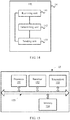
- FIG. 9 is a structural block diagram of UE in an embodiment of the present invention.
- UE 21 shown in FIG. 9 includes an obtaining unit 201, a determining unit 202, and a sending unit 203.
- the obtaining unit 201 is configured to obtain transmit power indication information of a first link.
- the determining unit 202 is configured to determine a first transmit power of control information and a second transmit power of data based on the transmit power indication information obtained by the obtaining unit 201.
- the sending unit 203 is configured to: send the control information on the first link at the first transmit power determined by the determining unit 202, and send the data on the first link at the second transmit power determined by the determining unit 202, where the control information and the data are in a same subframe.
- the transmit power indication information includes first indication information of a first maximum transmit power of the UE.
- the first indication information includes one piece of control information instructing to use maximum transmit powers for both the control information and the data, or the first indication information includes two independent pieces of control information respectively instructing to use maximum transmit powers for the control information and the data.
- control information and the data are carried in a same physical channel, or the control information is carried in a control channel of the first link, and the data is carried in a data channel of the first link.
- the determining unit 202 is specifically configured to determine the first transmit power and the second transmit power, so that a sum of a linear value of the first transmit power and a linear value of the second transmit power is equal to the first maximum transmit power, and a ratio of the first transmit power to the second transmit power is equal to a first preset value.
- the determining unit 202 is specifically configured to determine the first transmit power and the second transmit power, so that a sum of a linear value of the first transmit power and a linear value of the second transmit power is equal to the first maximum transmit power, and a difference between the first transmit power and the second transmit power is equal to a second preset value.
- the determining unit 202 is specifically configured to determine the first transmit power and the second transmit power, so that a sum of a linear value of the first transmit power and a linear value of the second transmit power is equal to the first maximum transmit power, and a difference between a transmit power on each physical resource block PRB of the control information and a transmit power on each PRB of the data is equal to a third preset value.
- the determining unit 202 is specifically configured to: determine a first power of the control information and a second power of the data based on transmission bandwidth of the first link and a path loss value of a second link between the UE and a serving base station of the UE; and determine the first transmit power and the second transmit power based on the first power, the second power, and the first maximum transmit power.
- the first transmit power is equal to the first power and that the second transmit power is equal to the second power.
- the first transmit power is equal to the first power or equal to a smaller one of the first power and the first maximum transmit power and that the second transmit power is equal to a difference between the linear value of the first maximum transmit power and a linear value of the first transmit power.
- a sum of a linear value of the first power and a linear value of the second power is less than the first maximum transmit power, it is determined that the first transmit power is equal to a sum of the first power and a first value and that the second transmit power is equal to a sum of the second power and a second value, where a sum of a linear value of the first transmit power and a linear value of the second transmit power is equal to the first maximum transmit power, and the first value and the second value meet a predefined relationship.
- the transmit power indication information further includes second indication information of a second maximum transmit power of the control information.
- the determining unit 202 is specifically configured to: use the second maximum transmit power as the first transmit power; and determine that the second transmit power is a difference between a linear value of the first maximum transmit power and a linear value of the first transmit power.
- the determining unit 202 is specifically configured to: determine a first power of the control information based on transmission bandwidth of the first link and a path loss value of a second link between the UE and a serving base station of the UE; use a smaller one of the first power and the second maximum transmit power as the first transmit power; and determine that the second transmit power is a difference between a linear value of the first maximum transmit power and a linear value of the first transmit power.
- the transmit power indication information further includes second indication information of a second maximum transmit power of the control information, and further includes third indication information of a third maximum transmit power of the data.
- the determining unit 202 is specifically configured to: determine a second power of the data based on transmission bandwidth of the first link and a path loss value of a second link between the UE and a serving base station of the UE; use the second maximum transmit power as the first transmit power, or use a smaller one of a first power and the second maximum transmit power as the first transmit power, where the first power is of the control information and is determined based on the transmission bandwidth and the path loss value; and use a smallest one of the second power, the third maximum transmit power, and a difference between a linear value of the first maximum transmit power and a linear value of the first transmit power as the second transmit power.
- the determining unit 202 is specifically configured to: determine a first power of the control information based on transmission bandwidth of the first link and a path loss value of a second link between the UE and a serving base station of the UE; use the third maximum transmit power as the second transmit power, or use a smaller one of a second power of the data and the third maximum transmit power as the second transmit power, where the second power is determined based on the transmission bandwidth and the path loss value; and use a smallest one of the first power, the second maximum transmit power, and a difference between a linear value of the first maximum transmit power and a linear value of the second transmit power as the first transmit power.
- the obtaining unit 201 may be implemented by a receiver
- the determining unit 202 may be implemented by a processor
- the sending unit 203 may be implemented by a transmitter.
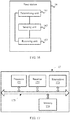
- UE 22 may include a processor 211, a receiver 212, a transmitter 213, and a memory 214.
- the memory 214 may be configured to store the first maximum transmit power, the second maximum transmit power, the third maximum transmit power, the first preset value, the second preset value, the third preset value, and the like, and may be further configured to store code executed by the processor 211, and the like.
- bus system 215. Components of the UE 22 are coupled together by a bus system 215.
- the bus system 215 includes a power bus, a control bus, and a status signal bus.
- the UE 21 shown in FIG. 9 or the UE 22 shown in FIG. 10 can implement the processes implemented by the UE in the method embodiment in FIG. 6 . To avoid repetition, details are not described herein again.
- a second maximum transmit power is marked as P CMAX,c , P CMAX , P EMAX , or P EMAX,c , and has any of the following meanings:
- a value of the second maximum transmit power herein may be a logarithmic value (whose unit may be dBm) or a linear value (whose unit may be mW), that is, may be a value corresponding to a single frequency-domain transmission resource (such as one PRB) or may be a value corresponding to entire transmission bandwidth.
- a power mentioned in subsequent embodiments of the present invention is of a logarithmic value or a linear value may be determined based on a unit of the power.
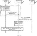
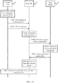
- FIG. 11 is a flowchart of a method for determining a first-link transmit power in an embodiment of the present invention.
- FIG. 11 shows first UE 31 and second UE 32.
- a first link is a link between the first UE 31 and the second UE 32.
- the first link herein may be a D2D link between two UEs, a sidelink (Sidelink) in V2V communication, or the like.
- the first UE 31 may be the UE 30 in FIG. 2 or FIG. 3 , that is, remote UE.
- the second UE 32 may be the UE 20 in FIG. 2 or FIG. 3 , that is, relay UE.
- the method shown in FIG. 11 includes the following steps.
- the second UE 32 determines a first maximum transmit power on the first link.
- the second UE 32 may obtain configuration information from a serving base station of the second UE 32.
- the configuration information may include a maximum transmit power P v, max available to the second UE 32.
- a link between the second UE 32 and the serving base station of the second UE 32 is a second link.
- the second link may be a cellular link.
- the second UE 31 may determine an open loop transmit power based on transmission bandwidth of the first link and a path loss value of the second link.
- a method for calculating the open loop transmit power refer to the prior art. For example, calculation is performed by using the following formula: 10 log 10 M + P O 1 + ⁇ 1 ⁇ PL , where M represents the transmission bandwidth of a channel on the first link, PL represents the path loss value of the second link, ⁇ 1 is a path loss compensation coefficient of the channel on the first link, and P O 1 is a power value configured or predefined by the serving base station.
- the channel on the first link herein may be a PSSCH.
- PL may be notified, after being determined by the serving base station, to the second UE 32 by the serving base station by using signaling, or may be determined by the second UE 32.
- a method for calculating a path loss value refer to the prior art. Details are not described herein.
- ⁇ 1 and P O 1 may be notified to the second UE 32 by the serving base station by using signaling.
- the configuration information sent by the serving base station includes values of ⁇ 1 and P O 1 .
- the second UE 32 may use a smaller one of the maximum transmit power P v ,max and the open loop transmit power as the first maximum transmit power.
- the second UE 32 sends a value of the first maximum transmit power.
- the second UE 32 may send, in a unicast mode or a broadcast mode, the value of the first maximum transmit power to remote UE that establishes a first link with the second UE 32.
- the second UE 32 sends the value of the first maximum transmit power to the first UE 31 in a unicast mode.
- the second UE 32 sends, in a broadcast mode, the value of the first maximum transmit power to all remote UEs that communicate with the second UE 32, and the remote UEs include the first UE 31.
- S201 and S202 in FIG. 11 may be replaced with S2011:
- a base station 10 sends indication information of the first maximum transmit power to the first UE 31.
- the base station 10 may send the indication information of the first maximum transmit power on a second link in a unicast mode or a broadcast mode.
- the first UE 31 may receive first indication information sent by the base station 10.
- the first indication information is indication information used to indicate the first maximum transmit power on the second link between the second UE 32 and the base station 10.
- the base station 10 may be the serving base station of the second UE 32.
- the first maximum transmit power may be configured by the base station 10 for the second UE 32.
- S2011 may be as follows: The base station 10 sends the indication information of the first maximum transmit power to the second UE 32, and the second UE 32 sends the indication information of the first maximum transmit power to the first UE 31 on the first link.
- sending performed in S2011 in FIG. 11 is not limited to direct sending and may alternatively be indirect sending.
- the second UE 32 may first send the indication information of the first maximum transmit power to the base station 10, and then S2011 is performed.
- the first UE 31 determines a first-link transmit power based on the first maximum transmit power.
- the first-link transmit power is marked as P firstlink .
- a maximum transmit power of the first UE 31 is a second maximum transmit power and is marked as P v 2 .
- the first UE 31 may use a smaller one of the first maximum transmit power and the second maximum transmit power as the first-link transmit power.
- P firstlink min ⁇ P v 1 , P v 2 ⁇ .
- the first UE 31 may determine a first power based on the transmission bandwidth of the first link and a path loss value of the first link, and use a smaller one of the first power and the first maximum transmit power as the first-link transmit power; or use a smallest one of the first power, the first maximum transmit power, and the second maximum transmit power as the first-link transmit power.
- the method before S203, the method further includes: obtaining, by the first UE 31, the path loss value of the first link. It should be noted that, this process may be performed before S202 or even before S201, or may be performed before or after S2011. This is not limited in the present invention.
- a manner of obtaining the path loss value of the first link by the first UE 31 is not limited in this embodiment of the present invention.
- the manner may be: sending first transmit power indication information of the first UE 31 to the second UE 32; and receiving the path loss value of the first link sent by the second UE 32, where the path loss value of the first link is determined by the second UE 32 based on the first transmit power indication information.
- the second UE 32 may calculate the path loss value of the first link and then notify the first UE of the path loss value.
- the manner may be: receiving second transmit power indication information of the second UE 32 sent by the second UE 32; and determining the path loss value of the first link based on the second transmit power indication information.
- the path loss value of the first link may be calculated by the first UE 31.
- a method for calculating a path loss value refer to the prior art. Details are not described herein.
- the first power is 10log 10 ( M ) + P O 2 + ⁇ 2 ⁇ PL firstlink , where M represents the transmission bandwidth of a channel on the first link, PL firstlink represents the path loss value of the first link, ⁇ 2 is a path loss compensation coefficient of the channel on the first link, and P O 2 is a power value configured or predefined by the serving base station.
- the channel on the first link herein may be a PSSCH.
- ⁇ 2 and P O 2 may be notified to the first UE 31 by the serving base station by using signaling.
- the configuration information sent by the serving base station includes values of ⁇ 2 and P O 2 .
- the first UE 31 and the second UE 32 transmit first-link data.
- the first UE 31 may send the first link data such as D2D data or sidelink data to the second UE 32 at the first-link transmit power.
- the determined first-link transmit power used for data transmission between the first UE and the second UE can be used for D2D communication or V2V communication between the two UEs. Therefore, efficiency of communication between the two UEs can be ensured.
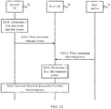
- the method may further include S2012. Details of S2012 are as follows: S2012.
- the first UE 31 receives indication information, sent by the base station 10, of a third maximum transmit power.
- the first UE 31 may receive second indication information sent by the base station 10.
- the second indication information includes the indication information used to indicate the third maximum transmit power of the first UE.
- the first UE 31 may receive the second indication information from the second UE 32.
- the base station 10 may send the second indication information on the second link between the base station 10 and the second UE 32 in a unicast mode or a broadcast mode, and then the second UE 32 sends the second indication information to the first UE 31 on the first link between the second UE 32 and the first UE 31 in the unicast mode or the broadcast mode.
- sending performed in S2012 in FIG. 12 is not limited to direct sending and may alternatively be indirect sending.
- the third maximum transmit power may be a maximum transmit power that is available to the first UE 31 and that is configured by the base station 10 for the first UE 31.
- the third maximum transmit power may be a maximum transmit power on each PRB.
- the first UE 31 may use a smallest one of a second maximum transmit power of the first UE, the first maximum transmit power, and the third maximum transmit power as the first-link transmit power; the first UE 31 may use a smaller one of a second maximum transmit power of the first UE and the third maximum transmit power as the first-link transmit power; or the first UE 31 may use a smaller one of the first maximum transmit power and the third maximum transmit power as the first-link transmit power.
- S201 and S202 refer to the related description in FIG. 11 .
- S201 and S202 may alternatively be replaced with S2011 for implementation, and the like. Details are not described herein again.
- the method further includes S2021 to S2025. Details of S2021 to S2025 are as follows.
- the second UE 32 sends an identity (Identity, ID) of a sequence.
- S2021 may alternatively be performed before S202 or even before S201, or S2021 and S202 may be performed simultaneously. This is not limited in the present invention.
- the second UE 32 may send information about the ID of the sequence on the first link in a unicast mode or a broadcast mode.
- the sequence may be carried in a synchronization signal on the first link, such as a sidelink synchronization signal (Sidelink Synchronization Signal, SLSS).
- SLSS Sidelink Synchronization Signal
- the ID of the sequence may be determined by the second UE 32, or may be notified, after being determined by the base station 10, to the second UE 32 by the base station 10 by using signaling.
- the ID of the sequence in S2021 may be a value associated with the second UE.
- different relay UEs may use different IDs of sequences.
- the ID of the sequence received by the first UE 31 may be the same as or may be different from an ID of a sequence received by another UE that communicates with the second UE 32.
- all remote UEs that can communicate with the second UE 32 by using the first link may use a same sequence ID, or may use mutually different sequence IDs. This is not limited in the present invention.
- the first UE 31 determines a second power.
- the first UE 31 may determine the second power based on the first maximum transmit power received in S202.
- S2021 may alternatively be performed after S2022. This is not limited in the present invention.
- a smaller one of the first maximum transmit power and the second maximum transmit power may be used as the second power, that is, min ⁇ P v 1 , P v 2 ⁇ .
- S1012 may be performed before S2022.
- a smallest one of the first maximum transmit power, the second maximum transmit power, and the third maximum transmit power is used as the second power, or in S2022, a smaller one of the first maximum transmit power and the third maximum transmit power is used as the second power, or in S2022, a smaller one of the second maximum transmit power and the third maximum transmit power is used as the second power. Details are not described herein.
- the first UE 31 sends the sequence at the second power.
- the first UE 31 sends, at the second power determined in S2022, the sequence received in S2021.
- the sequence may be carried in a synchronization signal on the first link.
- the synchronization signal on the first link may be an SLSS.
- the first UE 31 may send the sequence by using a sidelink resource.
- the sidelink resource may be a part of resources used for a cellular link, or may be a dedicated sidelink resource.
- the first UE 31 may send the sequence on the first link.
- the first UE 31 may send the sequence on a second link between the first UE 31 and the base station 10.
- the base station 10 determines power adjustment information.
- the base station 10 performs signal detection on a particular resource used by the sequence. During detection, the base station 10 determines a value relationship between a power of the received sequence and a power expected by the base station 10. The power of the sequence is greater than the expected power or the power of the sequence is less than the expected power.
- a frequency used for the sequence sent by the first UE 31 is an uplink spectrum used for a cellular link.
- a transmit power of the first UE 31 is excessively high, reception by the base station on the uplink cellular link is interfered with.
- the base station 10 determines that reception on the uplink cellular link is not interfered with if the detected power of the sequence is less than a particular threshold (which is the power expected by the base station 10), such as -100 dBm. If the detected power of the sequence is greater than the value, the base station may instruct to reduce a corresponding power for SLSS transmission corresponding to a corresponding SLSS ID.
- the base station 10 can detect sequences sent by a plurality of UEs.
- a plurality of remote UEs that communicate with one relay UE may send a same sequence or different sequences.
- the base station 10 may differentiate different relay UE groups by using IDs of sequences. For example, one relay UE and a plurality of remote UEs that communicate with the relay UE may be considered as one group of UEs, and use a first ID. Another relay UE and a plurality of remote UEs that communicate with the another relay UE may be considered as another group of UEs, and use a second ID.
- the base station 10 may indicate power adjustment values corresponding to the SLSS1, the SLSS2, the SLSS3 by using broadcast signaling or dedicated signaling.
- the power adjustment information may include a correspondence between an ID of a sequence and a power adjustment value, as shown in Table 1 below: Table 1 ID of an SLSS1 Power adjustment value 10 dB ID of an SLSS2 Power adjustment value 20 dB ID of an SLSS3 Power adjustment value 3 dB
- the base station 10 sends the power adjustment information.
- the base station 10 may send the power adjustment information by using broadcast signaling or dedicated signaling.
- the base station 10 may send the power adjustment information to all UEs or some UEs in a coverage area of the base station 10. For example, the base station 10 may send the power adjustment information to relay UE. For example, the base station 10 may send the power adjustment information to relay UE and remote UE.
- the first UE 31 determines a first-link transmit power.
- the first UE 31 determines the first-link transmit power based on the power adjustment information and the second power.
- the power adjustment information may be directly received by the first UE 31 from the base station 10, or the power adjustment information may be sent by the second UE 32 to the first UE 31 after being sent by the base station 10 to relay UE (that is, the second UE 32).
- the first UE 31 obtains, based on the ID of the sequence, a power adjustment value that is corresponding to the ID of the sequence and that is in the power adjustment information. Further, the first UE 31 may determine that the first-link transmit power is a difference between a linear value of the second power and a linear value of the power adjustment value, or may determine that the first-link transmit power is a difference between a logarithmic value of the second power and a logarithmic value of the power adjustment value.
- S201 and S202 refer to the related description in FIG. 11 .
- S201 and S202 may alternatively be replaced with S2011 for implementation, and the like. Details are not described herein again.
- the UE may determine the first-link transmit power based on the power adjustment information of the base station. This can prevent communication on a cellular link of the base station from being interfered with by transmission between UEs on the first link, and also can ensure efficiency of communication on the first link and communication on the second link.
- FIG. 14 is another structural block diagram of UE in an embodiment of the present invention.
- UE 14 shown in FIG. 14 is first UE, including a receiving unit 141 and a determining unit 142.
- the receiving unit 141 is configured to receive first indication information, where the first indication information includes indication information of a first maximum transmit power of second UE.
- the determining unit 142 is configured to determine the first-link transmit power based on the first indication information received by the receiving unit 141, where the first link is a link between the first UE and the second UE.
- the receiving unit 141 is specifically configured to receive the first indication information from the second UE or a base station.
- the UE 14 may receive, on the first link, the first indication information sent by the second UE.
- the UE 14 may receive, on a second link, the first indication information sent by the base station.
- the second link is a link between the UE 14 and the base station.
- the determining unit 142 is specifically configured to use a smaller one of a second maximum transmit power of the first UE and the first maximum transmit power as the first-link transmit power.
- the determining unit 142 is specifically configured to: determine a first power based on transmission bandwidth of the first link and a path loss value of the first link; and use a smaller one of the first maximum transmit power and the first power as the first-link transmit power; or use a smallest one of a second maximum transmit power of the first UE, the first maximum transmit power, and the first power as the first-link transmit power.
- the receiving unit 141 is further configured to receive indication information used to indicate an ID of a sequence used by the first UE, where the ID of the sequence used by the first UE has a same value as that of an ID of a sequence used by one or more other UEs that communicate with the second UE, or the ID of the sequence used by the first UE has a value different from that of an ID of a sequence used by one or more other UEs that communicate with the second UE, and the ID of the sequence used by the first UE is a value associated with the second UE.
- the UE 14 may further include a sending unit 143.
- the determining unit 142 is further configured to use a smaller one of a maximum transmit power of the first UE and the first maximum transmit power as a first transmit power;
- the sending unit 143 is configured to send the sequence at the first transmit power;
- the receiving unit 141 is further configured to receive adjustment indication information sent by the base station, where the adjustment indication information is generated by the base station based on the sequence; and the determining unit 142 is further configured to adjust the first transmit power based on the adjustment indication information to determine the first-link transmit power.
- the sending unit 143 is specifically configured to: send the sequence on a second link between the first UE and the base station; or send the sequence on the first link.
- the receiving unit 141 is further configured to receive second indication information sent by the second UE or the base station, where the second indication information includes indication information of a third maximum transmit power of the first UE.
- the determining unit 142 is specifically configured to use a smallest one of a second maximum transmit power of the first UE, the first maximum transmit power, and the third maximum transmit power as the first-link transmit power; or the determining unit 142 is specifically configured to use a smaller one of a second maximum transmit power of the first UE and the third maximum transmit power as the first-link transmit power; or the determining unit 142 is specifically configured to use a smaller one of the first maximum transmit power and the third maximum transmit power as the first-link transmit power.
- the third maximum transmit power may be a maximum transmit power on each PRB.
- the receiving unit 141 may be implemented by a receiver
- the determining unit 142 may be implemented by a processor
- the sending unit 143 may be implemented by a transmitter.
- UE 15 may include a processor 151, a receiver 152, a transmitter 153, and a memory 154.
- the memory 154 may be configured to store the first maximum transmit power, the second maximum transmit power, the third maximum transmit power, and the like, and may be further configured to store code executed by the processor 151, and the like.
- bus system 155 Components of the UE 15 are coupled together by a bus system 155.
- the bus system 155 includes a power bus, a control bus, and a status signal bus.
- the UE 14 shown in FIG. 14 or the UE 15 shown in FIG. 15 can implement the processes implemented by the first UE in the method embodiments in FIG. 11 to FIG. 13 . To avoid repetition, details are not described herein again.
- FIG. 16 is a structural block diagram of a base station in an embodiment of the present invention.
- a base station 16 shown in FIG. 16 includes a determining unit 161, a sending unit 162, and a receiving unit 163.
- the determining unit 161 is configured to perform signal detection to determine a first power of a sequence received from at least one first user equipment UE.
- the receiving unit 163 is configured to receive the sequence.
- the determining unit 161 is further configured to determine, based on the first power, power adjustment information corresponding to the first UE.
- the sending unit 162 is configured to send, to the first UE, the power adjustment information determined by the determining unit 161, so that the first UE determines a first-link transmit power, where the first link is a link between the first UE and second UE.
- the receiving unit 163 may be implemented by a receiver
- the determining unit 161 may be implemented by a processor
- the sending unit 162 may be implemented by a transmitter.
- a base station 17 may include a processor 171, a receiver 172, a transmitter 173, and a memory 174.
- the memory 174 may be configured to store a specific threshold, power adjustment information, and the like, and may be further configured to store code executed by the processor 171, and the like.
- the bus system 175 includes a power bus, a control bus, and a status signal bus.
- the base station 16 shown in FIG. 16 or the base station 17 shown in FIG. 17 can implement the processes implemented by the base station in the method embodiments in FIG. 11 to FIG. 13 . To avoid repetition, details are not described herein again.
- the processor in this embodiment of the present invention may be an integrated circuit chip and is capable of processing a signal.
- the steps in the foregoing method embodiments can be implemented by using a hardware integrated logic circuit in the processor, or by using instructions in a form of software.
- the processor may be a general purpose processor, a digital signal processor (Digital Signal Processor, DSP), an application-specific integrated circuit (Application Specific Integrated Circuit, ASIC), a field programmable gate array (Field Programmable Gate Array, FPGA) or another programmable logic device, a discrete gate or transistor logic device, or a discrete hardware component.
- DSP Digital Signal Processor
- ASIC Application Specific Integrated Circuit
- FPGA Field Programmable Gate Array
- the processor may implement or perform the methods, the steps, and logical block diagrams that are disclosed in the embodiments of the present invention.
- the general purpose processor may be a microprocessor or the processor may be any conventional processor or the like.
- the steps of the methods disclosed with reference to the embodiments of the present invention may be directly implemented by using a hardware decoding processor, or may be implemented by using a combination of hardware and software modules in a decoding processor.
- the software module may be located in a mature storage medium in the art, such as a random access memory, a flash memory, a read-only memory, a programmable read-only memory, an electrically erasable programmable memory, or a register.
- the storage medium is located in the memory, and the processor reads information in the memory and implements the steps in the foregoing methods in combination with hardware of the processor.
- the memory in the embodiments of the present invention may be a volatile memory or a nonvolatile memory, or may include both a volatile memory and a nonvolatile memory.
- the nonvolatile memory may be a read-only memory (Read-Only Memory, ROM), a programmable read-only memory (Programmable ROM, PROM), an erasable programmable read-only memory (Erasable PROM, EPROM), an electrically erasable programmable read-only memory (Electrically EPROM, EEPROM), or a flash memory.
- the volatile memory may be a random access memory (Random Access Memory, RAM), used as an external cache.
- RAMs may be used, such as a static random access memory (Static RAM, SRAM), a dynamic random access memory (Dynamic RAM, DRAM), a synchronous dynamic random access memory (Synchronous DRAM, SDRAM), a double data rate synchronous dynamic random access memory (Double Data Rate SDRAM, DDR SDRAM), an enhanced synchronous dynamic random access memory (Enhanced SDRAM, ESDRAM), a synchlink dynamic random access memory (Synchlink DRAM, SLDRAM), and a direct Rambus dynamic random access memory (Direct Rambus RAM, DR RAM).
- Static RAM static random access memory
- DRAM dynamic random access memory
- DRAM synchronous dynamic random access memory
- SDRAM double data rate synchronous dynamic random access memory
- Enhanced SDRAM, ESDRAM enhanced synchronous dynamic random access memory
- Synchlink DRAM, SLDRAM synchlink dynamic random access memory
- Direct Rambus RAM Direct Rambus RAM
- the disclosed system, apparatus, and method may be implemented in other manners.
- the described apparatus embodiment is merely an example.
- the unit division is merely logical function division and may be other division in actual implementation.
- a plurality of units or components may be combined or integrated into another system, or some features may be ignored or not performed.
- the displayed or discussed mutual couplings or direct couplings or communication connections may be implemented by using some interfaces.
- the indirect couplings or communication connections between the apparatuses or units may be implemented in electrical, mechanical, or other forms.
- the units described as separate parts may or may not be physically separate. Parts displayed as units may or may not be physical units, and may be located in one position or may be distributed on a plurality of network units. Some or all of the units may be selected based on actual requirements to achieve the objectives of the solutions of the embodiments.
- the functions When the functions are implemented in the form of a software functional unit and sold or used as an independent product, the functions may be stored in a computer-readable storage medium. Based on such an understanding, the technical solutions of the present invention essentially, or the part contributing to the prior art, or some of the technical solutions may be implemented in a form of a software product.
- the computer software product is stored in a storage medium, and includes several instructions for instructing a computer device (which may be a personal computer, a server, a network device, or the like) to perform all or some of the steps of the methods described in the embodiments of the present invention.
- the foregoing storage medium includes any medium that can store program code, such as a USB flash drive, a removable hard disk, a read-only memory (Read-Only Memory, ROM), a random access memory (Random Access Memory, RAM), a magnetic disk, or an optical disc.
- program code such as a USB flash drive, a removable hard disk, a read-only memory (Read-Only Memory, ROM), a random access memory (Random Access Memory, RAM), a magnetic disk, or an optical disc.
Landscapes
- Engineering & Computer Science (AREA)
- Computer Networks & Wireless Communication (AREA)
- Signal Processing (AREA)
- Mobile Radio Communication Systems (AREA)
Applications Claiming Priority (1)
| Application Number | Priority Date | Filing Date | Title |
|---|---|---|---|
| PCT/CN2016/073165 WO2017132825A1 (fr) | 2016-02-02 | 2016-02-02 | Procédé de vérification de puissance d'émission, équipement utilisateur et station de base |
Publications (3)
| Publication Number | Publication Date |
|---|---|
| EP3402255A1 true EP3402255A1 (fr) | 2018-11-14 |
| EP3402255A4 EP3402255A4 (fr) | 2018-12-19 |
| EP3402255B1 EP3402255B1 (fr) | 2021-03-31 |
Family
ID=59500524
Family Applications (1)
| Application Number | Title | Priority Date | Filing Date |
|---|---|---|---|
| EP16888650.5A Active EP3402255B1 (fr) | 2016-02-02 | 2016-02-02 | Procédé de vérification de puissance d'émission, équipement utilisateur et station de base |
Country Status (4)
| Country | Link |
|---|---|
| US (2) | US10764844B2 (fr) |
| EP (1) | EP3402255B1 (fr) |
| CN (4) | CN108029076B (fr) |
| WO (1) | WO2017132825A1 (fr) |
Cited By (3)
| Publication number | Priority date | Publication date | Assignee | Title |
|---|---|---|---|---|
| WO2021015864A1 (fr) * | 2019-07-22 | 2021-01-28 | Qualcomm Incorporated | Ajustement de propriété de transmission basé sur la réciprocité dans des communications de liaison latérale |
| WO2021015907A1 (fr) * | 2019-07-22 | 2021-01-28 | Qualcomm Incorporated | Ajustement de propriété de transmission basé sur une rétroaction dans des communications de liaison latérale |
| EP3913994A4 (fr) * | 2019-02-15 | 2022-01-12 | Guangdong Oppo Mobile Telecommunications Corp., Ltd. | Procédé et appareil de communication sans fil |
Families Citing this family (147)
| Publication number | Priority date | Publication date | Assignee | Title |
|---|---|---|---|---|
| CN110545575B (zh) * | 2016-04-23 | 2022-06-21 | 上海朗帛通信技术有限公司 | 一种窄带移动通信的方法和装置 |
| WO2017196968A1 (fr) | 2016-05-11 | 2017-11-16 | Idac Holdings, Inc. | Ensemble unité de données de protocole d'accès au support dans des systèmes sans fil |
| TWI674261B (zh) | 2017-02-17 | 2019-10-11 | 美商英能腫瘤免疫股份有限公司 | Nlrp3 調節劑 |
| EP3601355A1 (fr) | 2017-03-31 | 2020-02-05 | Bristol-Myers Squibb Company | Procédés de traitement de tumeur |
| TWI788340B (zh) | 2017-04-07 | 2023-01-01 | 美商必治妥美雅史谷比公司 | 抗icos促效劑抗體及其用途 |
| JP2020522495A (ja) | 2017-05-30 | 2020-07-30 | ブリストル−マイヤーズ スクイブ カンパニーBristol−Myers Squibb Company | 抗lag−3抗体、pd−1経路阻害剤および免疫療法剤の組み合わせを含む組成物 |
| CN110678200B (zh) | 2017-05-30 | 2024-05-17 | 百时美施贵宝公司 | 包含抗lag-3抗体或抗lag-3抗体和抗pd-1或抗pd-l1抗体的组合物 |
| ES2965352T3 (es) | 2017-05-30 | 2024-04-12 | Bristol Myers Squibb Co | Tratamiento de tumores positivos a gen 3 de activación de linfocitos (LAG-3) |
| KR20240149982A (ko) | 2017-06-01 | 2024-10-15 | 브리스톨-마이어스 스큅 컴퍼니 | 항-pd-1 항체를 사용하여 종양을 치료하는 방법 |
| US11344543B2 (en) | 2017-07-14 | 2022-05-31 | Innate Tumor Immunity, Inc. | NLRP3 modulators |
| SG11202000198QA (en) | 2017-08-04 | 2020-02-27 | Genmab As | Binding agents binding to pd-l1 and cd137 and use thereof |
| CN111247169A (zh) | 2017-10-15 | 2020-06-05 | 百时美施贵宝公司 | 治疗肿瘤的方法 |
| WO2019090330A1 (fr) | 2017-11-06 | 2019-05-09 | Bristol-Myers Squibb Company | Méthodes de traitement d'une tumeur |
| EP3743076A1 (fr) | 2018-01-22 | 2020-12-02 | Bristol-Myers Squibb Company | Compositions et méthodes de traitement du cancer |
| CA3096287A1 (fr) | 2018-01-22 | 2019-07-25 | Pascal Biosciences Inc. | Cannabinoides et leurs derives pour favoriser l'immunogenicite des cellules tumorales et infectees |
| EP3768715A1 (fr) | 2018-03-23 | 2021-01-27 | Bristol-Myers Squibb Company | Anticorps contre mica et/ou micb et leurs utilisations |
| KR20200139724A (ko) | 2018-03-30 | 2020-12-14 | 브리스톨-마이어스 스큅 컴퍼니 | 종양을 치료하는 방법 |
| PE20210160A1 (es) | 2018-04-25 | 2021-01-26 | Innate Tumor Immunity Inc | Moduladores de nlrp3 |
| CN112739371A (zh) | 2018-07-26 | 2021-04-30 | 百时美施贵宝公司 | 用于治疗癌症的lag-3组合疗法 |
| WO2020037091A1 (fr) | 2018-08-16 | 2020-02-20 | Innate Tumor Immunity, Inc. | Modulateurs de nlrp3 dérivés d'imidazo [4,5-c]quinoléine |
| WO2020037094A1 (fr) | 2018-08-16 | 2020-02-20 | Innate Tumor Immunity, Inc. | Composés de 4-amino-1h-imidazo[4,5-c] quinoléine substitués et procédés améliorés pour leur préparation |
| ES2974964T3 (es) | 2018-08-16 | 2024-07-02 | Innate Tumor Immunity Inc | Moduladores de NLRP3 derivados de imidazo[4,5-c]quinolina |
| LT4445958T (lt) | 2018-10-19 | 2025-12-10 | Bristol-Myers Squibb Company | Kompleksinė terapija, skirta melanomai gydyti |
| WO2020086724A1 (fr) | 2018-10-23 | 2020-04-30 | Bristol-Myers Squibb Company | Méthodes de traitement de tumeur |
| CN112840709B (zh) * | 2018-10-23 | 2022-10-11 | 华为技术有限公司 | 具有多接入点协调的通信系统中的上行功率控制系统和方法 |
| US11272482B2 (en) | 2018-11-01 | 2022-03-08 | Qualcomm Incorporated | Methods for transmission to achieve robust control and feedback performance in a network |
| WO2020087454A1 (fr) * | 2018-11-01 | 2020-05-07 | Oppo广东移动通信有限公司 | Procédé de régulation de puissance et dispositif terminal |
| CN113316590B (zh) | 2018-11-16 | 2025-02-28 | 百时美施贵宝公司 | 抗nkg2a抗体及其用途 |
| KR102835299B1 (ko) | 2018-12-04 | 2025-07-18 | 브리스톨-마이어스 스큅 컴퍼니 | 다중 동위원소체 반응 모니터링에 의한 샘플내 보정 곡선을 사용한 분석 방법 |
| KR20210108978A (ko) | 2018-12-21 | 2021-09-03 | 오제 이뮈노테라프틱스 | 이작용성 항-pd-1/il-7 분자 |
| MX2021007274A (es) | 2018-12-21 | 2021-07-15 | Ose Immunotherapeutics | Molecula bifuncional anti-pd-1/sirpa. |
| WO2020136133A1 (fr) | 2018-12-23 | 2020-07-02 | F. Hoffmann-La Roche Ag | Classification de tumeur basée sur une charge mutationnelle tumorale prédite |
| JP7377217B2 (ja) * | 2018-12-28 | 2023-11-09 | パナソニック インテレクチュアル プロパティ コーポレーション オブ アメリカ | 通信システムおよび通信方法 |
| US12338228B2 (en) | 2019-01-14 | 2025-06-24 | Innate Tumor Immunity, Inc. | NLRP3 modulators |
| CN113301963A (zh) | 2019-01-14 | 2021-08-24 | 先天肿瘤免疫公司 | 用于治疗癌症的作为nlrp3调节剂的取代的喹唑啉类 |
| WO2020150114A1 (fr) | 2019-01-14 | 2020-07-23 | Innate Tumor Immunity, Inc. | Modulateurs hétérocycliques de nlrp3, destinés à être utilisés dans le traitement du cancer |
| US12391675B2 (en) | 2019-01-14 | 2025-08-19 | Innate Tumor Immunity, Inc. | NLRP3 modulators |
| CN111511025B (zh) * | 2019-01-31 | 2023-05-23 | 华为技术有限公司 | 功率控制方法及终端设备 |
| CN111526473B (zh) | 2019-02-01 | 2022-03-29 | 上海朗帛通信技术有限公司 | 一种被用于无线通信的节点中的方法和装置 |
| KR20200099058A (ko) * | 2019-02-13 | 2020-08-21 | 삼성전자주식회사 | 무선 통신 시스템에서 단말의 송신전력 제어 방법 및 장치 |
| WO2020165374A1 (fr) | 2019-02-14 | 2020-08-20 | Ose Immunotherapeutics | Molécule bifonctionnelle comprenant il-15ra |
| KR20210146348A (ko) | 2019-03-28 | 2021-12-03 | 브리스톨-마이어스 스큅 컴퍼니 | 종양을 치료하는 방법 |
| WO2020198676A1 (fr) | 2019-03-28 | 2020-10-01 | Bristol-Myers Squibb Company | Méthodes de traitement de tumeur |
| US11006395B2 (en) * | 2019-03-29 | 2021-05-11 | Qualcomm Incorporated | Two stage control channel for peer-to-peer communication |
| CN113678517B (zh) * | 2019-04-08 | 2024-11-15 | 苹果公司 | 用于pscch覆盖增强的nr v2x侧链路结构 |
| KR20220016155A (ko) | 2019-05-30 | 2022-02-08 | 브리스톨-마이어스 스큅 컴퍼니 | 면역-종양학 (i-o) 요법에 적합한 대상체를 확인하는 방법 |
| US20220363760A1 (en) | 2019-05-30 | 2022-11-17 | Bristol-Myers Squibb Company | Multi-tumor gene signature for suitability to immuno-oncology therapy |
| WO2020243570A1 (fr) | 2019-05-30 | 2020-12-03 | Bristol-Myers Squibb Company | Signature de localisation cellulaire et polythérapie |
| US11362718B2 (en) * | 2019-06-17 | 2022-06-14 | Qualcomm Incorporated | Sidelink TX power control |
| WO2021024020A1 (fr) | 2019-08-06 | 2021-02-11 | Astellas Pharma Inc. | Polythérapie impliquant des anticorps dirigés contre la claudine 18.2 et inhibiteurs de point de contrôle immunitaire pour le traitement du cancer |
| US11601893B2 (en) * | 2019-08-15 | 2023-03-07 | Qualcomm Incorporated | Sidelink coordination for power control |
| WO2021034245A2 (fr) * | 2019-08-16 | 2021-02-25 | Telefonaktiebolaget Lm Ericsson (Publ) | Commande de puissance pour canal de commande de liaison latérale |
| WO2021055994A1 (fr) | 2019-09-22 | 2021-03-25 | Bristol-Myers Squibb Company | Profilage spatial quantitatif pour une thérapie par antagoniste de lag-3 |
| KR20220066950A (ko) | 2019-09-25 | 2022-05-24 | 브리스톨-마이어스 스큅 컴퍼니 | 암 요법을 위한 복합 바이오마커 |
| WO2021087691A1 (fr) * | 2019-11-04 | 2021-05-14 | Oppo广东移动通信有限公司 | Procédé de commande de puissance, procédé de détermination de ressource de transmission, dispositif, terminal et support |
| US20220390455A1 (en) | 2019-11-05 | 2022-12-08 | Bristol-Myers Squibb Company | M-protein assays and uses thereof |
| WO2021092221A1 (fr) | 2019-11-06 | 2021-05-14 | Bristol-Myers Squibb Company | Procédés d'identification d'un sujet atteint d'une tumeur appropriée pour une thérapie par inhibiteur de point de contrôle |
| WO2021092220A1 (fr) | 2019-11-06 | 2021-05-14 | Bristol-Myers Squibb Company | Procédés d'identification d'un sujet atteint d'une tumeur appropriée pour une thérapie par inhibiteur de point de contrôle |
| US20220411499A1 (en) | 2019-11-08 | 2022-12-29 | Bristol-Myers Squibb Company | LAG-3 Antagonist Therapy for Melanoma |
| WO2021097256A1 (fr) | 2019-11-14 | 2021-05-20 | Cohbar, Inc. | Peptides antagonistes de cxcr4 |
| WO2021122866A1 (fr) | 2019-12-17 | 2021-06-24 | Ose Immunotherapeutics | Molécules bifonctionnelles comprenant un variant de l'il-7 |
| IL294085A (en) | 2019-12-19 | 2022-08-01 | Bristol Myers Squibb Co | Combinations of dgk inhibitors and checkpoint antagonists |
| EP4087842A1 (fr) | 2020-01-10 | 2022-11-16 | Innate Tumor Immunity, Inc. | Modulateurs de nlrp3 |
| WO2021152005A1 (fr) | 2020-01-28 | 2021-08-05 | Universite De Strasbourg | Oligonucléotide antisens ciblant linc00518 pour le traitement du mélanome |
| CA3168923A1 (fr) | 2020-01-30 | 2021-08-05 | ONA Therapeutics S.L. | Polytherapie pour le traitement du cancer et de metastases cancereuses |
| JP2023514152A (ja) | 2020-02-06 | 2023-04-05 | ブリストル-マイヤーズ スクイブ カンパニー | Il-10およびその使用 |
| EP4114398A1 (fr) | 2020-03-06 | 2023-01-11 | Celgene Quanticel Research, Inc. | Combinaison d'un inhibiteur de lsd-1 et de nivolumab pour une utilisation dans le traitement du sclc ou du sqnsclc |
| AU2021232158A1 (en) | 2020-03-06 | 2022-09-29 | Ona Therapeutics, S.L. | Anti-CD36 antibodies and their use to treat cancer |
| CN115943312A (zh) | 2020-05-07 | 2023-04-07 | 法国居里学院 | 免疫抑制性成纤维细胞群体的生物标志物antxr1及其在预测对免疫疗法的反应中的用途 |
| KR20230035576A (ko) | 2020-07-07 | 2023-03-14 | 비온테크 에스이 | Hpv 양성 암 치료용 rna |
| IL300813A (en) | 2020-08-28 | 2023-04-01 | Bristol Myers Squibb Co | LAG-3 antagonist therapy for hepatocellular carcinoma |
| AU2021334361A1 (en) | 2020-08-31 | 2023-05-11 | Bristol-Myers Squibb Company | Cell localization signature and immunotherapy |
| CN116406369A (zh) | 2020-10-05 | 2023-07-07 | 百时美施贵宝公司 | 用于浓缩蛋白质的方法 |
| US20230364127A1 (en) | 2020-10-06 | 2023-11-16 | Codiak Biosciences, Inc. | Extracellular vesicle-aso constructs targeting stat6 |
| CA3193688A1 (fr) | 2020-10-09 | 2022-04-14 | Vladimir Lazar | Nouveau procede de prediction et signatures geniques pour le traitement du cancer |
| KR20230093282A (ko) | 2020-10-23 | 2023-06-27 | 브리스톨-마이어스 스큅 컴퍼니 | 폐암에 대한 lag-3 길항제 요법 |
| MX2023004847A (es) | 2020-10-28 | 2023-07-11 | Ikena Oncology Inc | Combinación de un inhibidor del receptor de hidrocarburos de arilo (ahr) con un inhibidor de pdx o doxorrubicina. |
| WO2022112198A1 (fr) | 2020-11-24 | 2022-06-02 | Worldwide Innovative Network | Procédé de sélection des thérapies optimales par points de contrôle immunitaire |
| WO2022120179A1 (fr) | 2020-12-03 | 2022-06-09 | Bristol-Myers Squibb Company | Signatures géniques multi-tumorales et leurs utilisations |
| US20240067727A1 (en) | 2020-12-17 | 2024-02-29 | Ose Immunotherapeutics | Bifunctional anti-pd1/il-7 molecules |
| WO2022135667A1 (fr) | 2020-12-21 | 2022-06-30 | BioNTech SE | Arn thérapeutique pour le traitement du cancer |
| TW202245808A (zh) | 2020-12-21 | 2022-12-01 | 德商拜恩迪克公司 | 用於治療癌症之治療性rna |
| WO2022135666A1 (fr) | 2020-12-21 | 2022-06-30 | BioNTech SE | Programme de traitement faisant intervenir des protéines cytokines |
| US20220233693A1 (en) | 2020-12-28 | 2022-07-28 | Bristol-Myers Squibb Company | Antibody Compositions and Methods of Use Thereof |
| JP2024501029A (ja) | 2020-12-28 | 2024-01-10 | ブリストル-マイヤーズ スクイブ カンパニー | Pd1/pd-l1抗体の皮下投与 |
| WO2022148781A1 (fr) | 2021-01-05 | 2022-07-14 | Institut Curie | Association d'activateurs de mcoln et d'inhibiteurs de point de contrôle immunitaire |
| TW202304506A (zh) | 2021-03-25 | 2023-02-01 | 日商安斯泰來製藥公司 | 涉及抗claudin 18.2抗體的組合治療以治療癌症 |
| CN117858719A (zh) | 2021-03-29 | 2024-04-09 | 朱诺治疗学股份有限公司 | 使用检查点抑制剂疗法和car t细胞疗法的组合进行给药和治疗的方法 |
| EP4314068A1 (fr) | 2021-04-02 | 2024-02-07 | The Regents Of The University Of California | Anticorps dirigés contre un cdcp1 clivé et leurs utilisations |
| MX2023011964A (es) | 2021-04-09 | 2024-01-08 | Ose Immunotherapeutics | Nuevo andamio para moléculas bifuncionales con propiedades mejoradas. |
| EP4320156A1 (fr) | 2021-04-09 | 2024-02-14 | Ose Immunotherapeutics | Échafaudage pour molécules bifonctionnelles comprenant des domaines de liaison pd-1 ou cd28 et sirp |
| CA3225254A1 (fr) | 2021-07-13 | 2023-01-19 | BioNTech SE | Agents de liaison multispecifiques contre cd40 et cd137 en polytherapie du cancer |
| KR20240042476A (ko) | 2021-07-30 | 2024-04-02 | 오엔에이 테라퓨틱스 에스.엘. | 항-cd36 항체 및 암을 치료하기 위한 이의 용도 |
| WO2023051926A1 (fr) | 2021-09-30 | 2023-04-06 | BioNTech SE | Traitement impliquant un arn non immunogène pour vaccination antigénique et antagonistes liant l'axe pd-1 |
| EP4413040A1 (fr) | 2021-10-06 | 2024-08-14 | Genmab A/S | Agents de liaison multispécifiques dirigés contre pd-l1 et cd137 en combinaison |
| TW202333802A (zh) | 2021-10-11 | 2023-09-01 | 德商拜恩迪克公司 | 用於肺癌之治療性rna(二) |
| CA3224890A1 (fr) | 2021-10-29 | 2023-05-04 | Bristol-Myers Squibb Company | Therapie par antagoniste de lag-3 pour cancer hematologique |
| WO2023083439A1 (fr) | 2021-11-09 | 2023-05-19 | BioNTech SE | Agoniste de tlr7 et combinaisons pour le traitement du cancer |
| KR20240135661A (ko) | 2022-01-26 | 2024-09-11 | 브리스톨-마이어스 스큅 컴퍼니 | 간세포성 암종에 대한 조합 요법 |
| WO2023164638A1 (fr) | 2022-02-25 | 2023-08-31 | Bristol-Myers Squibb Company | Polythérapie pour carcinome colorectal |
| WO2023168404A1 (fr) | 2022-03-04 | 2023-09-07 | Bristol-Myers Squibb Company | Méthodes de traitement d'une tumeur |
| JP2025508076A (ja) | 2022-03-08 | 2025-03-21 | アレンティス・セラピューティクス・アクチェンゲゼルシャフト | T細胞の利用能を向上させるための抗クローディン-1抗体の使用 |
| WO2023178329A1 (fr) | 2022-03-18 | 2023-09-21 | Bristol-Myers Squibb Company | Procédés d'isolement de polypeptides |
| WO2023196987A1 (fr) | 2022-04-07 | 2023-10-12 | Bristol-Myers Squibb Company | Méthodes de traitement d'une tumeur |
| JP7851417B2 (ja) | 2022-04-08 | 2026-04-24 | ブリストル-マイヤーズ スクイブ カンパニー | 三次リンパ組織様構造の機械学習識別、分類、及び定量化 |
| WO2023216147A1 (fr) * | 2022-05-11 | 2023-11-16 | 北京小米移动软件有限公司 | Procédé et appareil de configuration de puissance, dispositif, et support de stockage |
| EP4522657A1 (fr) | 2022-05-12 | 2025-03-19 | Genmab A/S | Agents de liaison capables de se lier à cd27 en polythérapie |
| KR20250022071A (ko) | 2022-06-02 | 2025-02-14 | 브리스톨-마이어스 스큅 컴퍼니 | 항체 조성물 및 이의 이용 방법 |
| WO2024003360A1 (fr) | 2022-07-01 | 2024-01-04 | Institut Curie | Biomarqueurs et leurs utilisations pour le traitement du neuroblastome |
| EP4310197A1 (fr) | 2022-07-21 | 2024-01-24 | Fundación para la Investigación Biomédica del Hospital Universitario Puerta de Hierro Majadahonda | Procédé pour identifier des patients atteints de cancer du poumon pour un traitement combiné d'immunothérapie et de chimiothérapie |
| CN119923267A (zh) | 2022-07-27 | 2025-05-02 | 阿斯利康(瑞典)有限公司 | 表达白介素-12的重组病毒与pd-1/pd-l1抑制剂的组合 |
| JP2025525886A (ja) | 2022-08-02 | 2025-08-07 | オーエスイー・イミュノセラピューティクス | Cd28に対する多機能性分子 |
| US20260015416A1 (en) | 2022-09-30 | 2026-01-15 | Alentis Therapeutics Ag | Treatment of drug-resistant hepatocellular carcinoma |
| EP4619435A1 (fr) | 2022-11-16 | 2025-09-24 | Boehringer Ingelheim International GmbH | Biomarqueurs d'efficacité prédictive pour anticorps anti-sirpa |
| EP4626552A1 (fr) | 2022-12-01 | 2025-10-08 | MedImmune Limited | Polythérapie comprenant des anticorps anti-pd-l1 et anti-cd73 pour le traitement du cancer |
| CN120302979A (zh) | 2022-12-01 | 2025-07-11 | 生物技术公司 | 针对CD40和CD137的多特异性抗体与抗PD1 Ab和化学治疗的组合治疗 |
| JP2026501506A (ja) | 2022-12-14 | 2026-01-16 | アステラス・ファーマ・ヨーロッパ・ベスローデン・フェンノートシャップ | Cldn18.2及びcd3に結合する二重特異性結合剤並びに免疫チェックポイント阻害剤を含む併用療法 |
| EP4638503A1 (fr) | 2022-12-21 | 2025-10-29 | Bristol-Myers Squibb Company | Polythérapie contre le cancer du poumon |
| WO2024150177A1 (fr) | 2023-01-11 | 2024-07-18 | Advesya | Méthodes de traitement de tumeurs solides |
| CN119522608A (zh) * | 2023-02-02 | 2025-02-25 | 中兴通讯股份有限公司 | 用于网络节点的同时回程链路和控制链路传输的系统和方法 |
| IL322506A (en) | 2023-02-23 | 2025-10-01 | Imcheck Therapeutics | Combinations of BTN3A activating antibody and immune checkpoint inhibitors |
| WO2024196952A1 (fr) | 2023-03-20 | 2024-09-26 | Bristol-Myers Squibb Company | Évaluation de sous-type de tumeur pour une thérapie anticancéreuse |
| EP4687991A1 (fr) | 2023-03-30 | 2026-02-11 | Ose Immunotherapeutics | Nanoparticule à base de lipide ciblant des cellules immunitaires activées pour l'expression d'une molécule d'amélioration de cellule immunitaire et son utilisation |
| WO2024200820A1 (fr) | 2023-03-30 | 2024-10-03 | Ose Immunotherapeutics | Procédé de synthèse de nanoparticule lipidique ciblée et ses utilisations |
| CN121620391A (zh) | 2023-04-06 | 2026-03-06 | 金麦安博股份有限公司 | 用于治疗癌症的针对pd-l1和cd137的多特异性结合剂 |
| TW202509071A (zh) | 2023-05-12 | 2025-03-01 | 丹麥商珍美寶股份有限公司 | 能夠與ox40結合之抗體、其變異體及其用途 |
| WO2024236048A1 (fr) | 2023-05-16 | 2024-11-21 | Nh Theraguix | Polythérapie pour le traitement de tumeurs par radiothérapie |
| EP4731681A1 (fr) | 2023-06-23 | 2026-04-29 | Imcheck Therapeutics | Anticorps bispécifiques ciblant btn3a et l'axe inhibiteur de pd-1/pd-l1 |
| WO2025038763A1 (fr) | 2023-08-15 | 2025-02-20 | Bristol-Myers Squibb Company | Procédé de chromatographie en flux continu d'hydroxyapatite céramique |
| WO2025056180A1 (fr) | 2023-09-15 | 2025-03-20 | BioNTech SE | Procédés de traitement faisant appel à des agents se liant à epcam et cd137 en combinaison avec des antagonistes de liaison à l'axe pd-1 |
| WO2025068452A1 (fr) | 2023-09-29 | 2025-04-03 | Negio Therapeutics | Dérivés du guanfacine et leur utilisation dans le traitement du cancer |
| WO2025068461A1 (fr) | 2023-09-29 | 2025-04-03 | Negio Therapeutics | Dérivés de guanfacine et leur utilisation dans le traitement du cancer |
| TW202540189A (zh) | 2023-11-30 | 2025-10-16 | 德商生物新技術公司 | 在組合療法中能夠結合ox40之抗體 |
| TW202541837A (zh) | 2023-12-08 | 2025-11-01 | 日商安斯泰來製藥公司 | 含有結合至cldn18.2和cd3之雙特異性結合劑和穩定或增加cldn18.2表現之藥劑之組合療法 |
| WO2026033885A1 (fr) | 2024-08-08 | 2026-02-12 | Astellas Pharma Inc. | Polythérapie faisant intervenir des agents de liaison bispécifiques se liant à cldn18.2 et cd3 et agents stabilisant ou augmentant l'expression de cldn18.2 |
| WO2025120867A1 (fr) | 2023-12-08 | 2025-06-12 | Astellas Pharma Inc. | Polythérapie impliquant des agents de liaison bispécifiques se liant à cldn18.2 et cd3 et anticorps anti-vegfr2 |
| WO2025120866A1 (fr) | 2023-12-08 | 2025-06-12 | Astellas Pharma Inc. | Polythérapie impliquant des agents de liaison bispécifiques se liant à cldn18.2 et cd3 et agents stabilisant ou augmentant l'expression de cldn18.2 |
| WO2025132831A1 (fr) | 2023-12-19 | 2025-06-26 | Universite D'aix-Marseille | Dérivés de n-hétéroaryle et leurs utilisations pour le traitement du cancer |
| WO2025133115A1 (fr) | 2023-12-21 | 2025-06-26 | Ose Immunotherapeutics | Nanoparticules à base de lipides comprenant de l'il-35 |
| WO2025145207A1 (fr) | 2023-12-29 | 2025-07-03 | Bristol-Myers Squibb Company | Polythérapie d'inhibiteur de kras et d'agent de déplétion des treg |
| US12521446B2 (en) | 2024-02-27 | 2026-01-13 | Bristol-Myers Squibb Company | Anti-CEACAM5 antibody drug conjugates |
| WO2025184208A1 (fr) | 2024-02-27 | 2025-09-04 | Bristol-Myers Squibb Company | Anticorps anti-ceacam5 et leurs utilisations |
| WO2025242835A1 (fr) | 2024-05-22 | 2025-11-27 | Ose Immunotherapeutics | Molécules comprenant des lieurs de masquage et leurs utilisations pour le traitement du cancer |
| WO2025242836A1 (fr) | 2024-05-22 | 2025-11-27 | Ose Immunotherapeutics | Molécules comprenant des lieurs de masquage et leurs utilisations pour le traitement de maladies et de troubles auto-immuns ou inflammatoires |
| WO2025245489A1 (fr) | 2024-05-24 | 2025-11-27 | Bristol-Myers Squibb Company | Traitement de tumeurs chez des sujets dont les échantillons sont positifs à fgl-1 |
| WO2025262250A1 (fr) | 2024-06-20 | 2025-12-26 | Negio Therapeutics | Dérivés de guanfacine et leurs utilisations |
| WO2026068705A1 (fr) | 2024-09-26 | 2026-04-02 | Ose Immunotherapeutics | Nanoparticules à base de lipides comprenant des domaines fc non glycosylés et leurs utilisations |
Family Cites Families (22)
| Publication number | Priority date | Publication date | Assignee | Title |
|---|---|---|---|---|
| US7151795B1 (en) * | 2001-12-31 | 2006-12-19 | Arraycomm Llc | Method and apparatus for increasing spectral efficiency using mitigated power near band-edge |
| US8839362B2 (en) * | 2006-07-31 | 2014-09-16 | Motorola Mobility Llc | Method and apparatus for managing transmit power for device-to-device communication |
| CN101247629A (zh) * | 2007-02-13 | 2008-08-20 | 杰脉通信技术(上海)有限公司 | 一种无线通信终端定位的方法及其应用 |
| CN102742333B (zh) * | 2010-02-02 | 2017-11-28 | Lg电子株式会社 | 无线局域网络中的发送功率控制的方法和设备 |
| CN102802270B (zh) * | 2011-05-27 | 2014-12-31 | 华为技术有限公司 | 随机接入的处理方法、基站、终端及系统 |
| CN103067140B (zh) * | 2011-10-20 | 2015-07-22 | 中兴通讯股份有限公司 | 控制信令发送方法及系统 |
| CN103139889B (zh) * | 2011-11-28 | 2015-09-09 | 华为技术有限公司 | D2d的功率控制方法、用户设备、基站和通讯系统 |
| CN103188811B (zh) * | 2011-12-31 | 2016-08-10 | 华为技术有限公司 | 传输子帧信息的方法、用户设备及基站 |
| GB2498713A (en) * | 2012-01-18 | 2013-07-31 | Renesas Mobile Corp | Power control for transmission of a discovery signal for a specific communication mode |
| WO2013113151A1 (fr) * | 2012-01-31 | 2013-08-08 | 富士通株式会社 | Procédé d'indication de signalisation pour attribution de puissance de liaison descendante, et station de base et équipement utilisateur correspondants |
| US9179425B2 (en) * | 2012-04-17 | 2015-11-03 | Ofinno Technologies, Llc | Transmit power control in multicarrier communications |
| US9807709B2 (en) * | 2012-05-31 | 2017-10-31 | Interdigital Patent Holdings, Inc. | Device to-device (D2D) cross link power control |
| CN103596258B (zh) | 2012-08-13 | 2018-08-17 | 中兴通讯股份有限公司 | 功率控制方法及基站 |
| EP2950595B1 (fr) * | 2013-01-24 | 2019-07-31 | LG Electronics Inc. | Procédé permettant de réguler la puissance d'émission d'un signal de découverte pour la communication de dispositif à dispositif dans un système de communication sans fil, et dispositif correspondant |
| KR101908951B1 (ko) * | 2013-02-07 | 2018-10-17 | 삼성전자주식회사 | 디바이스간 직접 통신 네트워크의 전송전력 제어 방법 및 장치 |
| CN104105185B (zh) * | 2013-04-03 | 2018-11-27 | 电信科学技术研究院 | 设备到设备通信中的发射功率控制方法、装置及系统 |
| CN104105189B (zh) * | 2013-04-12 | 2018-05-18 | 电信科学技术研究院 | 一种d2d传输的功率控制方法、系统和设备 |
| US20150094112A1 (en) * | 2013-09-27 | 2015-04-02 | Renesas Mobile Corporation | Power Control to Compensate Interference Level Changes |
| US9642099B2 (en) * | 2014-05-08 | 2017-05-02 | Futurewei Technologies, Inc. | System and method for power control command for device-to-device transmissions |
| CN104066205B (zh) * | 2014-07-03 | 2018-10-26 | 乐鑫信息科技(上海)有限公司 | 一种基于接收信号强度的设备连接方法及装置 |
| EP3016426B1 (fr) * | 2014-07-17 | 2019-03-27 | Huawei Technologies Co., Ltd. | Procédé de commande de puissance, noeud b et équipement utilisateur |
| CN104244315A (zh) | 2014-08-27 | 2014-12-24 | 乐视致新电子科技(天津)有限公司 | 一种控制网络接入设备发射功率的装置及其方法 |
-
2016
- 2016-02-02 CN CN201680054655.4A patent/CN108029076B/zh active Active
- 2016-02-02 CN CN202010112560.1A patent/CN111491361B/zh active Active
- 2016-02-02 EP EP16888650.5A patent/EP3402255B1/fr active Active
- 2016-02-02 CN CN202010112727.4A patent/CN111491362B/zh active Active
- 2016-02-02 CN CN202010099860.0A patent/CN111385767A/zh active Pending
- 2016-02-02 WO PCT/CN2016/073165 patent/WO2017132825A1/fr not_active Ceased
-
2018
- 2018-08-01 US US16/051,920 patent/US10764844B2/en active Active
-
2020
- 2020-07-29 US US16/942,451 patent/US10999805B2/en active Active
Cited By (9)
| Publication number | Priority date | Publication date | Assignee | Title |
|---|---|---|---|---|
| EP3913994A4 (fr) * | 2019-02-15 | 2022-01-12 | Guangdong Oppo Mobile Telecommunications Corp., Ltd. | Procédé et appareil de communication sans fil |
| US11425660B2 (en) | 2019-02-15 | 2022-08-23 | Guangdong Oppo Mobile Telecommunications Corp., Ltd. | Method and apparatus for dermining transmission power for sidelink channel |
| EP4240068A3 (fr) * | 2019-02-15 | 2023-11-15 | Guangdong Oppo Mobile Telecommunications Corp., Ltd. | Procédé et appareil de communication sans fil |
| US12289686B2 (en) | 2019-02-15 | 2025-04-29 | Guangdong Oppo Mobile Telecommunications Corp., Ltd. | Method and apparatus for dermining transmission power for sidelink channel |
| EP4593473A3 (fr) * | 2019-02-15 | 2025-10-15 | Guangdong Oppo Mobile Telecommunications Corp., Ltd. | Procédé et appareil de communication sans fil |
| WO2021015864A1 (fr) * | 2019-07-22 | 2021-01-28 | Qualcomm Incorporated | Ajustement de propriété de transmission basé sur la réciprocité dans des communications de liaison latérale |
| WO2021015907A1 (fr) * | 2019-07-22 | 2021-01-28 | Qualcomm Incorporated | Ajustement de propriété de transmission basé sur une rétroaction dans des communications de liaison latérale |
| US11265822B2 (en) | 2019-07-22 | 2022-03-01 | Qualcomm Incorporated | Reciprocity-based transmission property adjustment in sidelink communications |
| US11606761B2 (en) | 2019-07-22 | 2023-03-14 | Qualcomm Incorporated | Feedback-based transmission property adjustment in sidelink communications |
Also Published As
| Publication number | Publication date |
|---|---|
| US20180343626A1 (en) | 2018-11-29 |
| CN111491361B (zh) | 2023-10-24 |
| CN111491362B (zh) | 2023-10-24 |
| CN111491361A (zh) | 2020-08-04 |
| WO2017132825A1 (fr) | 2017-08-10 |
| CN111385767A (zh) | 2020-07-07 |
| CN111491362A (zh) | 2020-08-04 |
| CN108029076B (zh) | 2020-03-10 |
| US10999805B2 (en) | 2021-05-04 |
| CN108029076A (zh) | 2018-05-11 |
| US20200359341A1 (en) | 2020-11-12 |
| EP3402255B1 (fr) | 2021-03-31 |
| US10764844B2 (en) | 2020-09-01 |
| EP3402255A4 (fr) | 2018-12-19 |
Similar Documents
| Publication | Publication Date | Title |
|---|---|---|
| US10999805B2 (en) | Transmit power determining method, user equipment, and base station | |
| US11785551B2 (en) | Data transmission method and terminal device thereof | |
| EP4044745A1 (fr) | Procédé et appareil d'envoi et de réception de données | |
| Yang et al. | Enhanced autonomous resource selection for LTE-based V2V communication | |
| CN111096015B (zh) | 用于资源选择的方法和设备 | |
| EP3761739B1 (fr) | Procédé de communication, terminal et programme d'ordinateur | |
| CN108352946A (zh) | 用于共享通信介质上的短物理上行链路控制信道(pucch)的混合自动重复请求(harq)有效载荷映射 | |
| US20240389142A1 (en) | Channel occupancy time sharing between downlink and sidelink | |
| CN116234039B (zh) | 传输资源集合的方法和终端设备 | |
| CN115804202B (zh) | 无线通信方法、终端设备和网络设备 | |
| CN107733497A (zh) | 跟踪波束的方法、终端设备和网络侧设备 | |
| JP2018528704A (ja) | 車両用送信のための速度依存の送信フォーマット | |
| WO2020248259A1 (fr) | Procédé d'accès aléatoire, dispositif terminal et dispositif de réseau | |
| CN111096030A (zh) | 用于非授权频带通信的方法、设备和计算机可读存储介质 | |
| WO2019192012A1 (fr) | Création d'une unité de données de protocole pour transmission précoce de données | |
| EP4033834B1 (fr) | Dispositif et procédé de sélection de ressource | |
| KR20230149341A (ko) | 채널 점유 시간 및 관련된 무선 노드들을 결정하는 방법 | |
| CN112438029A (zh) | 反馈信息的方法、终端、芯片和存储介质 | |
| WO2023097554A1 (fr) | Réservation de ressource de liaison latérale efficace | |
| CN115699813B (zh) | 传输反馈信息的方法、终端设备和网络设备 | |
| WO2020156214A1 (fr) | Procédé de commande de puissance et dispositif terminal |
Legal Events
| Date | Code | Title | Description |
|---|---|---|---|
| STAA | Information on the status of an ep patent application or granted ep patent |
Free format text: STATUS: THE INTERNATIONAL PUBLICATION HAS BEEN MADE |
|
| PUAI | Public reference made under article 153(3) epc to a published international application that has entered the european phase |
Free format text: ORIGINAL CODE: 0009012 |
|
| STAA | Information on the status of an ep patent application or granted ep patent |
Free format text: STATUS: REQUEST FOR EXAMINATION WAS MADE |
|
| 17P | Request for examination filed |
Effective date: 20180809 |
|
| AK | Designated contracting states |
Kind code of ref document: A1 Designated state(s): AL AT BE BG CH CY CZ DE DK EE ES FI FR GB GR HR HU IE IS IT LI LT LU LV MC MK MT NL NO PL PT RO RS SE SI SK SM TR |
|
| AX | Request for extension of the european patent |
Extension state: BA ME |
|
| A4 | Supplementary search report drawn up and despatched |
Effective date: 20181116 |
|
| RIC1 | Information provided on ipc code assigned before grant |
Ipc: H04W 52/10 20090101ALN20181112BHEP Ipc: H04W 52/36 20090101ALN20181112BHEP Ipc: H04W 52/54 20090101ALN20181112BHEP Ipc: H04W 52/32 20090101ALI20181112BHEP Ipc: H04W 52/24 20090101ALN20181112BHEP Ipc: H04W 52/38 20090101ALN20181112BHEP Ipc: H04W 52/00 20090101AFI20181112BHEP Ipc: H04W 52/34 20090101ALI20181112BHEP Ipc: H04W 52/08 20090101ALN20181112BHEP Ipc: H04W 52/28 20090101ALI20181112BHEP |
|
| DAV | Request for validation of the european patent (deleted) | ||
| DAX | Request for extension of the european patent (deleted) | ||
| GRAP | Despatch of communication of intention to grant a patent |
Free format text: ORIGINAL CODE: EPIDOSNIGR1 |
|
| STAA | Information on the status of an ep patent application or granted ep patent |
Free format text: STATUS: GRANT OF PATENT IS INTENDED |
|
| INTG | Intention to grant announced |
Effective date: 20201014 |
|
| GRAS | Grant fee paid |
Free format text: ORIGINAL CODE: EPIDOSNIGR3 |
|
| GRAA | (expected) grant |
Free format text: ORIGINAL CODE: 0009210 |
|
| STAA | Information on the status of an ep patent application or granted ep patent |
Free format text: STATUS: THE PATENT HAS BEEN GRANTED |
|
| AK | Designated contracting states |
Kind code of ref document: B1 Designated state(s): AL AT BE BG CH CY CZ DE DK EE ES FI FR GB GR HR HU IE IS IT LI LT LU LV MC MK MT NL NO PL PT RO RS SE SI SK SM TR |
|
| REG | Reference to a national code |
Ref country code: GB Ref legal event code: FG4D Ref country code: CH Ref legal event code: EP |
|
| REG | Reference to a national code |
Ref country code: DE Ref legal event code: R096 Ref document number: 602016055449 Country of ref document: DE Ref country code: AT Ref legal event code: REF Ref document number: 1378385 Country of ref document: AT Kind code of ref document: T Effective date: 20210415 |
|
| REG | Reference to a national code |
Ref country code: IE Ref legal event code: FG4D |
|
| REG | Reference to a national code |
Ref country code: LT Ref legal event code: MG9D |
|
| PG25 | Lapsed in a contracting state [announced via postgrant information from national office to epo] |
Ref country code: BG Free format text: LAPSE BECAUSE OF FAILURE TO SUBMIT A TRANSLATION OF THE DESCRIPTION OR TO PAY THE FEE WITHIN THE PRESCRIBED TIME-LIMIT Effective date: 20210630 Ref country code: NO Free format text: LAPSE BECAUSE OF FAILURE TO SUBMIT A TRANSLATION OF THE DESCRIPTION OR TO PAY THE FEE WITHIN THE PRESCRIBED TIME-LIMIT Effective date: 20210630 Ref country code: FI Free format text: LAPSE BECAUSE OF FAILURE TO SUBMIT A TRANSLATION OF THE DESCRIPTION OR TO PAY THE FEE WITHIN THE PRESCRIBED TIME-LIMIT Effective date: 20210331 Ref country code: HR Free format text: LAPSE BECAUSE OF FAILURE TO SUBMIT A TRANSLATION OF THE DESCRIPTION OR TO PAY THE FEE WITHIN THE PRESCRIBED TIME-LIMIT Effective date: 20210331 |
|
| PG25 | Lapsed in a contracting state [announced via postgrant information from national office to epo] |
Ref country code: LV Free format text: LAPSE BECAUSE OF FAILURE TO SUBMIT A TRANSLATION OF THE DESCRIPTION OR TO PAY THE FEE WITHIN THE PRESCRIBED TIME-LIMIT Effective date: 20210331 Ref country code: RS Free format text: LAPSE BECAUSE OF FAILURE TO SUBMIT A TRANSLATION OF THE DESCRIPTION OR TO PAY THE FEE WITHIN THE PRESCRIBED TIME-LIMIT Effective date: 20210331 Ref country code: SE Free format text: LAPSE BECAUSE OF FAILURE TO SUBMIT A TRANSLATION OF THE DESCRIPTION OR TO PAY THE FEE WITHIN THE PRESCRIBED TIME-LIMIT Effective date: 20210331 |
|
| REG | Reference to a national code |
Ref country code: NL Ref legal event code: MP Effective date: 20210331 |
|
| REG | Reference to a national code |
Ref country code: AT Ref legal event code: MK05 Ref document number: 1378385 Country of ref document: AT Kind code of ref document: T Effective date: 20210331 |
|
| PG25 | Lapsed in a contracting state [announced via postgrant information from national office to epo] |
Ref country code: LT Free format text: LAPSE BECAUSE OF FAILURE TO SUBMIT A TRANSLATION OF THE DESCRIPTION OR TO PAY THE FEE WITHIN THE PRESCRIBED TIME-LIMIT Effective date: 20210331 Ref country code: CZ Free format text: LAPSE BECAUSE OF FAILURE TO SUBMIT A TRANSLATION OF THE DESCRIPTION OR TO PAY THE FEE WITHIN THE PRESCRIBED TIME-LIMIT Effective date: 20210331 Ref country code: EE Free format text: LAPSE BECAUSE OF FAILURE TO SUBMIT A TRANSLATION OF THE DESCRIPTION OR TO PAY THE FEE WITHIN THE PRESCRIBED TIME-LIMIT Effective date: 20210331 Ref country code: AT Free format text: LAPSE BECAUSE OF FAILURE TO SUBMIT A TRANSLATION OF THE DESCRIPTION OR TO PAY THE FEE WITHIN THE PRESCRIBED TIME-LIMIT Effective date: 20210331 Ref country code: SM Free format text: LAPSE BECAUSE OF FAILURE TO SUBMIT A TRANSLATION OF THE DESCRIPTION OR TO PAY THE FEE WITHIN THE PRESCRIBED TIME-LIMIT Effective date: 20210331 Ref country code: NL Free format text: LAPSE BECAUSE OF FAILURE TO SUBMIT A TRANSLATION OF THE DESCRIPTION OR TO PAY THE FEE WITHIN THE PRESCRIBED TIME-LIMIT Effective date: 20210331 |
|
| PG25 | Lapsed in a contracting state [announced via postgrant information from national office to epo] |
Ref country code: SK Free format text: LAPSE BECAUSE OF FAILURE TO SUBMIT A TRANSLATION OF THE DESCRIPTION OR TO PAY THE FEE WITHIN THE PRESCRIBED TIME-LIMIT Effective date: 20210331 Ref country code: RO Free format text: LAPSE BECAUSE OF FAILURE TO SUBMIT A TRANSLATION OF THE DESCRIPTION OR TO PAY THE FEE WITHIN THE PRESCRIBED TIME-LIMIT Effective date: 20210331 Ref country code: PL Free format text: LAPSE BECAUSE OF FAILURE TO SUBMIT A TRANSLATION OF THE DESCRIPTION OR TO PAY THE FEE WITHIN THE PRESCRIBED TIME-LIMIT Effective date: 20210331 Ref country code: PT Free format text: LAPSE BECAUSE OF FAILURE TO SUBMIT A TRANSLATION OF THE DESCRIPTION OR TO PAY THE FEE WITHIN THE PRESCRIBED TIME-LIMIT Effective date: 20210802 Ref country code: IS Free format text: LAPSE BECAUSE OF FAILURE TO SUBMIT A TRANSLATION OF THE DESCRIPTION OR TO PAY THE FEE WITHIN THE PRESCRIBED TIME-LIMIT Effective date: 20210731 |
|
| REG | Reference to a national code |
Ref country code: DE Ref legal event code: R097 Ref document number: 602016055449 Country of ref document: DE |
|
| PG25 | Lapsed in a contracting state [announced via postgrant information from national office to epo] |
Ref country code: AL Free format text: LAPSE BECAUSE OF FAILURE TO SUBMIT A TRANSLATION OF THE DESCRIPTION OR TO PAY THE FEE WITHIN THE PRESCRIBED TIME-LIMIT Effective date: 20210331 Ref country code: DK Free format text: LAPSE BECAUSE OF FAILURE TO SUBMIT A TRANSLATION OF THE DESCRIPTION OR TO PAY THE FEE WITHIN THE PRESCRIBED TIME-LIMIT Effective date: 20210331 Ref country code: ES Free format text: LAPSE BECAUSE OF FAILURE TO SUBMIT A TRANSLATION OF THE DESCRIPTION OR TO PAY THE FEE WITHIN THE PRESCRIBED TIME-LIMIT Effective date: 20210331 |
|
| PLBE | No opposition filed within time limit |
Free format text: ORIGINAL CODE: 0009261 |
|
| STAA | Information on the status of an ep patent application or granted ep patent |
Free format text: STATUS: NO OPPOSITION FILED WITHIN TIME LIMIT |
|
| 26N | No opposition filed |
Effective date: 20220104 |
|
| PG25 | Lapsed in a contracting state [announced via postgrant information from national office to epo] |
Ref country code: IS Free format text: LAPSE BECAUSE OF FAILURE TO SUBMIT A TRANSLATION OF THE DESCRIPTION OR TO PAY THE FEE WITHIN THE PRESCRIBED TIME-LIMIT Effective date: 20210731 |
|
| PG25 | Lapsed in a contracting state [announced via postgrant information from national office to epo] |
Ref country code: IT Free format text: LAPSE BECAUSE OF FAILURE TO SUBMIT A TRANSLATION OF THE DESCRIPTION OR TO PAY THE FEE WITHIN THE PRESCRIBED TIME-LIMIT Effective date: 20210331 |
|
| PG25 | Lapsed in a contracting state [announced via postgrant information from national office to epo] |
Ref country code: MC Free format text: LAPSE BECAUSE OF FAILURE TO SUBMIT A TRANSLATION OF THE DESCRIPTION OR TO PAY THE FEE WITHIN THE PRESCRIBED TIME-LIMIT Effective date: 20210331 |
|
| REG | Reference to a national code |
Ref country code: CH Ref legal event code: PL |
|
| REG | Reference to a national code |
Ref country code: BE Ref legal event code: MM Effective date: 20220228 |
|
| PG25 | Lapsed in a contracting state [announced via postgrant information from national office to epo] |
Ref country code: LU Free format text: LAPSE BECAUSE OF NON-PAYMENT OF DUE FEES Effective date: 20220202 |
|
| PG25 | Lapsed in a contracting state [announced via postgrant information from national office to epo] |
Ref country code: FR Free format text: LAPSE BECAUSE OF NON-PAYMENT OF DUE FEES Effective date: 20220228 |
|
| PG25 | Lapsed in a contracting state [announced via postgrant information from national office to epo] |
Ref country code: LI Free format text: LAPSE BECAUSE OF NON-PAYMENT OF DUE FEES Effective date: 20220228 Ref country code: IE Free format text: LAPSE BECAUSE OF NON-PAYMENT OF DUE FEES Effective date: 20220202 Ref country code: CH Free format text: LAPSE BECAUSE OF NON-PAYMENT OF DUE FEES Effective date: 20220228 |
|
| PG25 | Lapsed in a contracting state [announced via postgrant information from national office to epo] |
Ref country code: BE Free format text: LAPSE BECAUSE OF NON-PAYMENT OF DUE FEES Effective date: 20220228 |
|
| P01 | Opt-out of the competence of the unified patent court (upc) registered |
Effective date: 20230524 |
|
| PG25 | Lapsed in a contracting state [announced via postgrant information from national office to epo] |
Ref country code: HU Free format text: LAPSE BECAUSE OF FAILURE TO SUBMIT A TRANSLATION OF THE DESCRIPTION OR TO PAY THE FEE WITHIN THE PRESCRIBED TIME-LIMIT; INVALID AB INITIO Effective date: 20160202 |
|
| PG25 | Lapsed in a contracting state [announced via postgrant information from national office to epo] |
Ref country code: MK Free format text: LAPSE BECAUSE OF FAILURE TO SUBMIT A TRANSLATION OF THE DESCRIPTION OR TO PAY THE FEE WITHIN THE PRESCRIBED TIME-LIMIT Effective date: 20210331 Ref country code: CY Free format text: LAPSE BECAUSE OF FAILURE TO SUBMIT A TRANSLATION OF THE DESCRIPTION OR TO PAY THE FEE WITHIN THE PRESCRIBED TIME-LIMIT Effective date: 20210331 |
|
| PG25 | Lapsed in a contracting state [announced via postgrant information from national office to epo] |
Ref country code: TR Free format text: LAPSE BECAUSE OF FAILURE TO SUBMIT A TRANSLATION OF THE DESCRIPTION OR TO PAY THE FEE WITHIN THE PRESCRIBED TIME-LIMIT Effective date: 20210331 |
|
| PG25 | Lapsed in a contracting state [announced via postgrant information from national office to epo] |
Ref country code: MT Free format text: LAPSE BECAUSE OF FAILURE TO SUBMIT A TRANSLATION OF THE DESCRIPTION OR TO PAY THE FEE WITHIN THE PRESCRIBED TIME-LIMIT Effective date: 20210331 |
|
| PG25 | Lapsed in a contracting state [announced via postgrant information from national office to epo] |
Ref country code: GR Free format text: LAPSE BECAUSE OF NON-PAYMENT OF DUE FEES Effective date: 20210331 |
|
| PG25 | Lapsed in a contracting state [announced via postgrant information from national office to epo] |
Ref country code: GR Free format text: LAPSE BECAUSE OF NON-PAYMENT OF DUE FEES Effective date: 20210331 |
|
| PGFP | Annual fee paid to national office [announced via postgrant information from national office to epo] |
Ref country code: GB Payment date: 20260106 Year of fee payment: 11 |
|
| PGFP | Annual fee paid to national office [announced via postgrant information from national office to epo] |
Ref country code: DE Payment date: 20251230 Year of fee payment: 11 |