EP3402700B1 - Kopplungsvorrichtung zur schwingfähigen befestigung eines gassackmoduls an einem fahrzeuglenkrad - Google Patents
Kopplungsvorrichtung zur schwingfähigen befestigung eines gassackmoduls an einem fahrzeuglenkrad Download PDFInfo
- Publication number
- EP3402700B1 EP3402700B1 EP17749711.2A EP17749711A EP3402700B1 EP 3402700 B1 EP3402700 B1 EP 3402700B1 EP 17749711 A EP17749711 A EP 17749711A EP 3402700 B1 EP3402700 B1 EP 3402700B1
- Authority
- EP
- European Patent Office
- Prior art keywords
- steering wheel
- coupling device
- base body
- wheel base
- mounting member
- Prior art date
- Legal status (The legal status is an assumption and is not a legal conclusion. Google has not performed a legal analysis and makes no representation as to the accuracy of the status listed.)
- Active
Links
Images


Classifications
-
- F—MECHANICAL ENGINEERING; LIGHTING; HEATING; WEAPONS; BLASTING
- F16—ENGINEERING ELEMENTS AND UNITS; GENERAL MEASURES FOR PRODUCING AND MAINTAINING EFFECTIVE FUNCTIONING OF MACHINES OR INSTALLATIONS; THERMAL INSULATION IN GENERAL
- F16F—SPRINGS; SHOCK-ABSORBERS; MEANS FOR DAMPING VIBRATION
- F16F7/00—Vibration-dampers; Shock-absorbers
- F16F7/10—Vibration-dampers; Shock-absorbers using inertia effect
- F16F7/1028—Vibration-dampers; Shock-absorbers using inertia effect the inertia-producing means being a constituent part of the system which is to be damped
-
- B—PERFORMING OPERATIONS; TRANSPORTING
- B60—VEHICLES IN GENERAL
- B60R—VEHICLES, VEHICLE FITTINGS, OR VEHICLE PARTS, NOT OTHERWISE PROVIDED FOR
- B60R21/00—Arrangements or fittings on vehicles for protecting or preventing injuries to occupants or pedestrians in case of accidents or other traffic risks
- B60R21/02—Occupant safety arrangements or fittings, e.g. crash pads
- B60R21/16—Inflatable occupant restraints or confinements designed to inflate upon impact or impending impact, e.g. air bags
- B60R21/20—Arrangements for storing inflatable members in their non-use or deflated condition; Arrangement or mounting of air bag modules or components
- B60R21/203—Arrangements for storing inflatable members in their non-use or deflated condition; Arrangement or mounting of air bag modules or components in steering wheels or steering columns
-
- B—PERFORMING OPERATIONS; TRANSPORTING
- B60—VEHICLES IN GENERAL
- B60Q—ARRANGEMENT OF SIGNALLING OR LIGHTING DEVICES, THE MOUNTING OR SUPPORTING THEREOF OR CIRCUITS THEREFOR, FOR VEHICLES IN GENERAL
- B60Q5/00—Arrangement or adaptation of acoustic signal devices
- B60Q5/001—Switches therefor
- B60Q5/003—Switches therefor mounted on the steering wheel
-
- B—PERFORMING OPERATIONS; TRANSPORTING
- B60—VEHICLES IN GENERAL
- B60R—VEHICLES, VEHICLE FITTINGS, OR VEHICLE PARTS, NOT OTHERWISE PROVIDED FOR
- B60R21/00—Arrangements or fittings on vehicles for protecting or preventing injuries to occupants or pedestrians in case of accidents or other traffic risks
- B60R21/02—Occupant safety arrangements or fittings, e.g. crash pads
- B60R21/16—Inflatable occupant restraints or confinements designed to inflate upon impact or impending impact, e.g. air bags
- B60R21/20—Arrangements for storing inflatable members in their non-use or deflated condition; Arrangement or mounting of air bag modules or components
- B60R21/203—Arrangements for storing inflatable members in their non-use or deflated condition; Arrangement or mounting of air bag modules or components in steering wheels or steering columns
- B60R21/2035—Arrangements for storing inflatable members in their non-use or deflated condition; Arrangement or mounting of air bag modules or components in steering wheels or steering columns using modules containing inflator, bag and cover attachable to the steering wheel as a complete sub-unit
- B60R21/2037—Arrangements for storing inflatable members in their non-use or deflated condition; Arrangement or mounting of air bag modules or components in steering wheels or steering columns using modules containing inflator, bag and cover attachable to the steering wheel as a complete sub-unit the module or a major component thereof being yieldably mounted, e.g. for actuating the horn switch or for protecting the driver in a non-deployment situation
-
- B—PERFORMING OPERATIONS; TRANSPORTING
- B60—VEHICLES IN GENERAL
- B60R—VEHICLES, VEHICLE FITTINGS, OR VEHICLE PARTS, NOT OTHERWISE PROVIDED FOR
- B60R21/00—Arrangements or fittings on vehicles for protecting or preventing injuries to occupants or pedestrians in case of accidents or other traffic risks
- B60R21/02—Occupant safety arrangements or fittings, e.g. crash pads
- B60R21/16—Inflatable occupant restraints or confinements designed to inflate upon impact or impending impact, e.g. air bags
- B60R21/23—Inflatable members
- B60R21/235—Inflatable members characterised by their material
-
- B—PERFORMING OPERATIONS; TRANSPORTING
- B62—LAND VEHICLES FOR TRAVELLING OTHERWISE THAN ON RAILS
- B62D—MOTOR VEHICLES; TRAILERS
- B62D1/00—Steering controls, i.e. means for initiating a change of direction of the vehicle
- B62D1/02—Steering controls, i.e. means for initiating a change of direction of the vehicle vehicle-mounted
- B62D1/04—Hand wheels
- B62D1/11—Hand wheels incorporating energy-absorbing arrangements, e.g. by being yieldable or collapsible
-
- F—MECHANICAL ENGINEERING; LIGHTING; HEATING; WEAPONS; BLASTING
- F16—ENGINEERING ELEMENTS AND UNITS; GENERAL MEASURES FOR PRODUCING AND MAINTAINING EFFECTIVE FUNCTIONING OF MACHINES OR INSTALLATIONS; THERMAL INSULATION IN GENERAL
- F16F—SPRINGS; SHOCK-ABSORBERS; MEANS FOR DAMPING VIBRATION
- F16F7/00—Vibration-dampers; Shock-absorbers
- F16F7/10—Vibration-dampers; Shock-absorbers using inertia effect
- F16F7/104—Vibration-dampers; Shock-absorbers using inertia effect the inertia member being resiliently mounted
- F16F7/108—Vibration-dampers; Shock-absorbers using inertia effect the inertia member being resiliently mounted on plastics springs
-
- B—PERFORMING OPERATIONS; TRANSPORTING
- B60—VEHICLES IN GENERAL
- B60R—VEHICLES, VEHICLE FITTINGS, OR VEHICLE PARTS, NOT OTHERWISE PROVIDED FOR
- B60R21/00—Arrangements or fittings on vehicles for protecting or preventing injuries to occupants or pedestrians in case of accidents or other traffic risks
- B60R21/02—Occupant safety arrangements or fittings, e.g. crash pads
- B60R21/16—Inflatable occupant restraints or confinements designed to inflate upon impact or impending impact, e.g. air bags
- B60R21/23—Inflatable members
- B60R21/235—Inflatable members characterised by their material
- B60R2021/23504—Inflatable members characterised by their material characterised by material
Definitions
- the invention relates to a coupling device for the vibration-capable fastening of an airbag module to a steering wheel base body of a vehicle steering wheel, and to an assembly and a vehicle steering wheel with such a coupling device.
- vibrations occur when the vehicle is idling or in certain speed ranges, which the driver perceives as disturbing. These vibrations are due, among other things, to the rigid coupling of the steering wheel to the steering column.
- vibration absorbers it is known to use so-called vibration absorbers to avoid the undesired steering wheel vibrations in order to tune the natural frequency of the overall system so that it is in a non-critical range.
- the gas generator of an airbag module arranged in the steering wheel is currently used as the counter-oscillating absorber mass.
- the vibration damping improves with increasing absorber mass, is in the DE 37 10 173 C2
- the entire gas bag module is advantageously used as absorber mass.
- the first natural frequency of the steering wheel / module system can be tuned so low via the shear stiffness of the vibration dampers that it comes to rest in a speed range of the vehicle in which no high excitation amplitudes occur (for example, around 120 km / h).
- the vibration absorbers are currently also used to implement a horn function on the vehicle steering wheel, with a horn contact on the gas bag module and a corresponding mating contact on Steering wheel body are provided.
- a vehicle steering wheel is for example in the US 8,720,942 B2 disclosed.
- the generic EP 1 834 843 A2 discloses a vehicle steering wheel with a coupling device according to the preamble of claim 1, with a steering wheel skeleton, an airbag module and a positioning plate arranged between the steering wheel skeleton and the airbag module, the positioning plate for the realization of a horn function first being resiliently attached to the steering wheel skeleton and subsequently the airbag module firmly attached to the by a latching connection Positioning plate is fixed.
- the object of the invention is to provide a structurally simple vehicle steering wheel with vibration damper, in which a horn function is integrated which, with high functional reliability, has the shortest possible actuation travel and the lowest possible actuation force.
- this object is achieved by a coupling device for the oscillatable fastening of a prefabricated airbag module to a steering wheel base body of a vehicle steering wheel, with a fastening body which has an axial underside with respect to a steering wheel axis, which faces the steering wheel base body in the assembled state of the vehicle steering wheel, and an opposite axial top surface, which faces a gas bag module in the assembled state of the vehicle steering wheel, a bearing surface provided on the axial underside for a damping element for the oscillatable coupling of the fastening body to the steering wheel base body, and a latching element arranged on the upper side of the fastening body for latching with the gas bag module, the latching element being designed such that the gas bag module can be coupled to the fastening body essentially axially immovable or axially displaceable to a limited extent by means of a latching connection, and wherein the coupling device has a damping element which is attached to the contact surface on the axial underside of the Fast
- the horn function and the vibration damping function are separated from one another in a simple manner, so that vibration excitation of the steering column and the firmly connected steering wheel base body (for example on rough roads) is initially dampened between the steering wheel base body and the fastening body and no longer has a direct effect on the module-side horn function ,
- a swingable coupling of the fastening body with the steering wheel base body by the damping element is to be understood in the context of this application in such a way that the damping element enables damped oscillation between the fastening body and the steering wheel base body at least transversely to the steering wheel axis, preferably also in the direction of the steering wheel axis.
- the maximum amplitude of a possible vibration in the direction of the steering wheel axis is preferably smaller than an axial actuation path for triggering a vehicle horn.
- the fastening body of the coupling device is preferably a fastening plate which extends essentially perpendicular to the steering wheel axis and in particular has a plurality of latching elements, the latching elements preferably being made in one piece with the fastening plate.
- the locking elements can have an identical distance from the steering wheel axis and can be arranged evenly distributed in the circumferential direction. This results in a simple and quick assembly of the coupling device and a stable mounting of the gas bag module.
- a plurality of separate fastening bodies, each with a locking element are provided for the vibration-capable fastening of the gas bag module to the steering wheel base body.
- a damping element can be assigned to each latching element, the latching elements and associated damping elements being arranged axially one behind the other.
- a horn contact or an actuating element for triggering a horn signal upon contact between the horn contact and a mating contact arranged on the gas bag module is on the axial upper side of the fastening body, the latching element being designed such that the gas bag module can be displaced axially to a limited extent by the latching connection the fastening body can be coupled.
- the entire airbag module for actuating the vehicle horn is axially displaced in this case, both the horn contact and the mating contact being formed on components of the vehicle steering wheel which are mounted so as to be capable of oscillation.
- the coupling device has a damping element, which rests in the area of the contact surface on the axial underside of the fastening body and couples the fastening body to the steering wheel base body so that it can vibrate, so that the fastening body and the Steering wheel base bodies are movable relative to one another at least transversely to the steering wheel axis, in particular wherein the damping element is preassembled on the axial underside of the fastening body.
- the damping element comprises a vibration-damping material and optionally stop elements and / or mounting sleeves which adjoin the vibration-damping material.
- the damping element preferably extends through an opening in the fastening body.
- the damping element can comprise a ring-shaped, vibration-damping material with a radial shoulder, an edge of the fastening body opening forming a contact surface and engaging on the radial shoulder of the vibration-damping material.
- the radial shoulder in the vibration-damping material is designed as a groove, the edge of the fastening body opening engaging at least in sections in the groove. This enables quick and easy axial positioning and fixing of the damping element on the fastening body.
- the limitation of the receiving space for the vibration-damping material by components that are present anyway, such as the fastening body, the screw head and / or the steering wheel base body, is particularly advantageous because separate mounting sleeves and / or stop elements can then be dispensed with.
- the damping element is then ideally formed exclusively by the vibration-damping material.
- the invention comprises an assembly with a steering wheel base body, a coupling device described above and a damping element for the oscillatable coupling of the fastening body to the steering wheel base body, the damping element being arranged on the axial underside of the fastening body and preassembled together with the fastening body on the steering wheel base body.
- the invention also includes an assembly with a prefabricated airbag module and a coupling device described above, the airbag module, in particular a module base of the airbag module, having a mating contact axially adjacent to the horn contact, and the airbag module being mounted so as to be axially displaceable relative to the fastening body in order to trigger a horn signal ,
- the invention relates to an assembly comprising a prefabricated airbag module and a coupling device described above, the airbag module having a (manually operable) module cover with a horn contact and a further module component with a counter contact axially adjacent to the horn contact, the module cover being relative to triggering a horn signal is axially displaceably mounted to the further module component.
- the horn function is implemented "within" the gas bag module, the horn contact and the mating contact also being formed on components of the vehicle steering wheel which are mounted so as to be capable of vibration in this embodiment variant.
- a vehicle steering wheel of a motor vehicle with a steering wheel base body, a prefabricated airbag module, a coupling device described above and a damping element for the oscillatable coupling of the fastening body to the steering wheel base body, the vehicle steering wheel having a horn contact and an axially adjacent to the horn contact Has counter contact, and both the horn contact and the counter contact are formed on components of the vehicle steering wheel which are mounted so as to be capable of oscillation.
- the coupling device and the damping element here form an absorber unit, which is preassembled on the steering wheel base body.
- the prefabricated absorber unit is first connected, in particular screwed, to the steering wheel base body, whereupon the gas bag module, which is also prefabricated, is fed axially until it engages with the absorber unit and is thereby fastened to the steering wheel base body.
- the gas bag module is attached to the base of the steering wheel exclusively by the snap-in connection with the coupling device.
- an additional (latching) connection is provided between the gas bag module and the steering wheel base body, which allows a limited relative movement in normal driving operation of the vehicle, but when the gas bag module is activated, it ensures that the gas bag module does not completely move away Steering wheel base body releases. Consequently, the airbag module in this embodiment is fastened to the steering wheel base body by means of the coupling device, a further connection between the airbag module and the steering wheel base body being provided that is independent of the coupling device. This is advantageous because in this case the connections to the coupling device do not have to be designed for the extreme loads that occur, for example, when the gas bag module is activated.
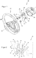
- the Figure 1 shows a vehicle steering wheel 10 with a steering wheel base body 12, a prefabricated gas bag module 14 and a coupling device 16 for the vibration-capable attachment of the gas bag module 14 to the steering wheel base body 12.
- the coupling device 16 comprises a fastening body 18 which has an axial underside 20 with respect to a steering wheel axis A, which faces the steering wheel base body 12 in the assembled state of the vehicle steering wheel 10, and an opposite axial top side 22 which faces the gas bag module 14 in the assembled state of the vehicle steering wheel 10 is.
- the latching element 28 is designed such that the gas bag module 14 can be coupled to the fastening body 18 essentially axially immovable or axially displaceable to a limited extent by means of a latching connection.
- the fastening body 18 is in accordance with Figure 1 a mounting plate that extends perpendicular to the steering wheel axis A and has three locking elements 28.
- the fastening body 18 is here a metal part which is made in one piece with the latching elements 28, the latching elements 28 being at an identical distance from the steering wheel axis A and being arranged evenly distributed in the circumferential direction.
- design variants are also conceivable in which the fastening body 18 is made from a robust plastic.
- the coupling device 16 has three damping elements 26, which each abut a contact surface 24 on the axial underside 20 of the fastening plate.
- a damping element 26 is assigned to each latching element 28, the latching elements 28 and the associated damping elements 26 each being arranged axially one behind the other.
- FIG 2 shows a detail section through the vehicle steering wheel 10 according to Figure 1 in the area of a damping element 26 and its associated latching element 28.
- the damping element 26 comprises a vibration-damping material 27, for example an elastomer, as well as two stop elements 30 and a mounting sleeve 32, each of which adjoins the vibration-damping material 27.
- the stop elements 30 are arranged axially on both sides of the vibration-damping material 27, while the mounting sleeve 32 extends axially between the stop elements 30.
- the steering wheel base body 12 generally comprises a steering wheel skeleton with a steering wheel rim, at least one spoke as well as a hub 34 and a hub plate 36.
- the steering wheel base body 12 generally also comprises a foam 38, for example made of polyurethane, which at least partially surrounds the steering wheel skeleton.
- the damping element 26 is in accordance with Figure 2 attached to the steering wheel skeleton via the mounting sleeve 32, the mounting sleeve 32 and the hub plate 36 forming, for example, a bayonet connection.
- fastening body 18 with the molded-on locking element 28 is connected here by a screw 40 to the damping element 26 and via the damping element 26 to the steering wheel skeleton.
- the vibration-damping material 27 can already be connected in advance, for example by vulcanization, to the mounting sleeve 32 and the stop elements 30 in order to form the prefabricated damping element 26 with them. Then the mounting sleeve 32 of each individual damping element 26 is fastened in the manner of a bayonet lock on the steering wheel base body 12, specifically on the hub plate 36 of the steering wheel base body 12. Finally, the fastening body 18 is inserted with its molded-on locking elements 28 and connected to the individual damping elements 26 by the screws 40.
- the locking elements 28 of the coupling device 16 are according to the Figures 1 and 2 in each case rigid latching hooks which, when the prefabricated gas bag module 14 is axially plugged in, dip into module sockets 42 and latch with a spring wire 43 mounted on the gas bag module 14.
- the Figure 3 shows a vehicle steering wheel 10, which is according to the steering wheel construction Figure 1 differs only by another embodiment of the coupling device 16. In order to avoid repetitions, reference is therefore generally made to the above description and the following mainly deals with differences.
- the coupling device 16 Compared to the embodiment according to Figure 1 has the coupling device 16 according to Figure 3 another, particularly advantageous with a view to the assembly effort on the steering wheel body 12 on. Instead of the stop elements 30 and mounting sleeves 32, the coupling device 16 has a base plate 44 for mounting the fastening body 18 on the steering wheel base body 12.
- the vibration-damping material 27 forms the damping element 26 and can be connected beforehand to the fastening body 18 and the base plate 44, for example by vulcanization, so that the damping element 26 is part of the prefabricated coupling device 16.
- the base plate 44 of the coupling device 16 then only has to be fastened to the steering wheel base body 12, the base plate 44 in the present exemplary embodiment being specifically screwed to the hub plate 36 of the steering wheel base body 12 by a screw 46.
- the base plate 44 to be foamed into the encapsulation 38 at least at the edge and thereby to be attached to the steering wheel base body 12.
- catch elements can be provided directly on the steering wheel base body 12, which are spaced apart from the gas bag module 14 during normal driving operation and only act directly on the gas bag module 14 when the module is activated and the module 14 hold back.
- These catch elements are, for example, catch hooks or catch hooks 80 formed on the steering wheel skeleton of the steering wheel base body 12 (see Figure 12 ).
- the vehicle steering wheel 10 has a horn contact 50 and a mating contact 52 axially adjacent to the horn contact 50, both the horn contact 50 and the mating contact 52 being formed on components of the vehicle steering wheel 10 which are mounted so as to be capable of oscillation.
- components that are mounted such that they can vibrate are, for example, the fastening body 18 of the coupling device 16 and the gas bag module 14 with all of its module components.
- the Figure 5 shows an assembly for the vehicle steering wheel 10, with a prefabricated gas bag module 14 and a coupling device 16, which has a horn contact 50 on the top 22 of the fastening body 18 for triggering a horn signal.
- the gas bag module 14 has a mating contact 52 axially adjacent to the horn contact 50, the (entire) gas bag module 14 being mounted so as to be axially displaceable relative to the fastening body 18 in order to trigger the horn signal.
- the prefabricated airbag module 14 is coupled to the fastening body 18 so as to be axially displaceable to a limited extent via the latching connection with the latching elements 28 of the coupling device 16 in the assembled state of the vehicle steering wheel 10.
- the Figure 6 shows a further assembly for the vehicle steering wheel 10, which differs from the embodiment according to Figure 5 differs only in that the airbag module 14 has both the horn contact 50 and the mating contact 52 axially spaced from the horn contact 50.
- the oscillatingly mounted mounting body 18 has axially adjacent to the horn contact 50 at least one axially protruding actuating element 53, two hook-like projections being provided as actuating elements 53 in the variant shown.
- the (entire) gas bag module 14 is then moved axially against a spring force in the direction of the fastening body 18, the horn contact 50 being deformed or displaced in the direction of the mating contact 52 by the at least one actuating element 53 until the desired horn signal is reached when the contacts touch sounds.
- the Figure 7 finally shows yet another embodiment of the assembly for the vehicle steering wheel 10, with a prefabricated gas bag module 14 and a coupling device 16, the horn function being integrated in the gas bag module 14.
- the prefabricated gas bag module 14 has a module cover 54 with the horn contact 50 and a further module component 56 with the counter contact 52 axially adjacent to the horn contact 50, the Module cover 54 for triggering the horn signal is axially displaceable relative to the further module component 56.
- the horn is actuated in accordance with Figure 7 thus not by moving the entire airbag module 14, but by a relative movement between the module cover 54 and the further module component 56, for example a module housing.
- all the design variants have in common that all of the components required for horn actuation, such as horn contacts 50, mating contacts 52 and / or actuating elements 53, are mounted such that they can vibrate on the steering wheel base body 12.
- the components required for the horn actuation are, in other words, all part of the absorber mass of the steering wheel vibration absorber.
- the damping element 26 consists of the vibration-damping material 27, which is ring-shaped and has a radial shoulder on the outside.
- the fastening body opening 58 has an opening edge with radially inwardly projecting projections 60, 62 which form the contact surface 24 for the damping element 26 and act on the radial shoulder of the vibration-damping material 27.
- the radial shoulder in the vibration-damping material 27 is in accordance with Figure 11 designed as a circumferential groove 64, the opening edge, specifically the projections 60 of the opening edge engaging in the groove 64.
- the elastic ring made of vibration-damping material 27 can be quickly and easily inserted into the opening 58, so that the damping element 26 is axially positioned and fixed on the fastening body 18 with minimal effort.
- Each projection 60 of the fastening body 18 has an axial underside 20 facing the steering wheel base body 12 and forms a contact surface 24 for the damping element 26, which in the present case corresponds to the ring-shaped vibration-damping material 27.
- FIGS. 8 and 9 show an assembly with a steering wheel base body 12, a coupling device 16 and a screw 66 for mounting the coupling device 16 on the steering wheel base body 12, the screw 66 extending through the ring-shaped vibration-damping material 27.
- the screw 66 extends from a screw head 68 in the axial direction via a screw shaft 70 to a free shaft end 72.
- the screw shaft 70 is designed in a stepped manner with a spacing section 74 adjoining the screw head 68 and one to the free shaft end 72 threaded portion 76 adjacent to the spacing portion 74, which is separated from the spacing portion 74 by a step 78.
- the threaded section 76 has a smaller shaft diameter than the spacer section 74 and is screwed into the hub plate 36 of the steering wheel base body 12 until the step 78 abuts the hub plate 36 and prevents further screwing in.
- the locking element 28 extends in the axial direction from the fastening body 18 to a free end and is essentially hollow-cylindrical, a locking projection being formed on the free end.
- An outer diameter of the screw head 68 is slightly smaller than an inner diameter of the locking element 28, so that the screw 66 can be inserted into the locking element 28 and extends through the opening 58 of the fastening body 18 into the hub plate 36. This screwing of the fastening body 18 in the area of the locking element 28 contributes to a particularly compact design of the coupling device 16.
- FIG. 9 is an axial dimension of the spacing portion 74 of the screw 66 slightly larger than an axial dimension of the fastening body 18 in the region of the damping element 26, so that a certain movement of the fastening body 18 relative to the steering wheel base body 12 is possible for vibration damping.
- An axial dimension of the damping element 26 is at least as large as the axial dimension of the spacing section 74, so that the vibration-damping material 27 is positioned axially when the screw 66 is screwed in and is preferably slightly compressed.
- the groove 64 in the vibration-damping material 27 is arranged such that the fastening body 18 in an unexcited rest position of the vehicle steering wheel 10 is held axially at a distance from the screw head 68 and the hub plate 36, in particular essentially axially centrally between the screw head 68 and the hub plate 36, via its projections 60 which engage in the groove 64.
- the projections 62 of the fastening body 18 axially adjoining the screw head 68 also have axial undersides 20 facing the steering wheel base body 12, each of which forms a contact surface 24 for the damping element 26.
- the projections 60 serve as stops of the fastening body 18 on the screw head 68 in order to determine a maximum relative movement between the fastening body 18 and the steering wheel base body 12.
- the vibration-damping material 27 rests with an axial end face at least in sections on the screw head 68 of the screw 66 and with an opposite axial end face at least in sections against the steering wheel base body 12.
- a receiving space for the vibration-damping material 27 is thus defined in the axial direction by the screw head 68 and the steering wheel base body 12 and in the radial direction by the spacing section 74 of the screw shaft 70 and the fastening body 18. Therefore, separate stop elements 30 and mounting sleeves 32 (as for example in FIG Figure 2 shown) can be dispensed with.
- a coupling device 16 and a steering wheel base body 12 are provided, a fastening body 18 of the coupling device 16 designed as a fastening plate being connected to the steering wheel base body 12 so as to be capable of oscillation, and latching elements 28 for latching with the gas bag module 14.
- catch elements are provided on the steering wheel base body 12, which are spaced apart from the gas bag module 14 in normal driving operation and only act directly on the gas bag module 14 and hold it back when the module is activated.
- These capture elements are in accordance Figure 12 locking hooks 80 formed on the steering wheel skeleton of the steering wheel base body 12.
- the Figure 13 shows the vehicle steering wheel 10 according to Figure 12 with a coupling device 16 according to Figure 9 and an assembled airbag module 14. It is clear that the spring wire 43, which is firmly connected to the airbag module 14, engages both in the locking elements 28 of the coupling device 16 and in the locking hooks 80 of the steering wheel base body 12.
Landscapes
- Engineering & Computer Science (AREA)
- Mechanical Engineering (AREA)
- General Engineering & Computer Science (AREA)
- Physics & Mathematics (AREA)
- Acoustics & Sound (AREA)
- Chemical & Material Sciences (AREA)
- Combustion & Propulsion (AREA)
- Transportation (AREA)
- Air Bags (AREA)
- Steering Controls (AREA)
- Vibration Prevention Devices (AREA)
Description
- Die Erfindung betrifft eine Kopplungsvorrichtung zur schwingfähigen Befestigung eines Gassackmoduls an einem Lenkradgrundkörper eines Fahrzeuglenkrads sowie eine Baugruppe und ein Fahrzeuglenkrad mit einer solchen Kopplungsvorrichtung.
- Bei vielen Fahrzeuglenkrädern treten im Leerlauf oder in bestimmten Geschwindigkeitsbereichen des Fahrzeugs Vibrationen auf, die vom Fahrer als störend empfunden werden. Diese Vibrationen sind unter anderem auf die starre Kopplung des Lenkrads mit der Lenksäule zurückzuführen.
- Es ist bekannt, zur Vermeidung der unerwünschten Lenkradschwingungen sogenannte Schwingungstilger einzusetzen, um die Eigenfrequenz des Gesamtsystems so abzustimmen, dass sie in einem unkritischen Bereich liegt. Derzeit wird als gegenschwingende Tilgermasse beispielsweise der Gasgenerator eines im Lenkrad angeordneten Gassackmoduls eingesetzt.
- Da sich die Schwingungstilgung mit zunehmender Tilgermasse verbessert, ist in der
DE 37 10 173 C2 bereits eine Kraftfahrzeuglenkung beschrieben, bei der in vorteilhafter Weise das gesamte Gassackmodul als Tilgermasse genutzt wird. Über die Schersteifigkeit der eingesetzten Schwingungsdämpfer lässt sich die erste Eigenfrequenz des Systems Lenkrad/Modul so niedrig abstimmen, dass sie in einem Geschwindigkeitsbereich des Fahrzeugs zu liegen kommt, in dem noch keine hohen Anregungsamplituden auftreten (beispielsweise bei etwa 120 km/h). - Bei schwingfähigen Gassackmodulen werden die Schwingungstilger derzeit auch genutzt, um eine Hupenfunktion am Fahrzeuglenkrad zu realisieren, wobei ein Hupenkontakt am Gassackmodul und ein entsprechender Gegenkontakt am Lenkradgrundkörper vorgesehen sind. Ein solches Fahrzeuglenkrad ist beispielsweise in der
US 8,720,942 B2 offenbart. - Es hat sich allerdings herausgestellt, dass es bei solchen Lenkrädern insbesondere auf Schlechtwegstrecken zu Fehlauslösungen der Fahrzeughupe kommt oder im Vergleich zu Lenkrädern ohne Schwingungstilgung größere Kontaktierwege bzw. höhere Kontaktierkräfte zum Auslösen der Fahrzeughupe notwendig sind. Dies führt zu unerwünscht großen Spaltmaßen am Fahrzeuglenkrad und Komfortbeeinträchtigungen beim Betätigen der Fahrzeughupe.
- In der
DE 10 2009 050 893 A1 ist ein Fahrzeuglenkrad mit einem Gassackmodul und einem Lenkradkörper beschrieben, wobei das Gassackmodul mit einer am Lenkradkörper befestigten Montageplatte verrastet ist. Vorgeschlagen wird dabei eine Rastverbindung, die im Fahrbetrieb unerwünschte Klappergeräusche verhindern soll. - Die gattungsgemäße
EP 1 834 843 A2 offenbart ein Fahrzeuglenkrad mit einer Kupplungsvorrichtung gemäß dem Oberbegriff des Patentanspruchs 1, mit einem Lenkradskelett, einem Gassackmodul und einer zwischen Lenkradskelett und Gassackmodul angeordneten Positionierungsplatte, wobei die Positionierungsplatte zur Realisierung einer Hupenfunktion zunächst federnd am Lenkradskelett befestigt und nachfolgend das Gassackmodul durch eine Rastverbindung fest an der Positionierungsplatte fixiert wird. - Aufgabe der Erfindung ist es, ein konstruktiv einfach aufgebautes Fahrzeuglenkrad mit Schwingungstilger zu schaffen, bei dem eine Hupenfunktion integriert ist, die bei hoher Funktionssicherheit einen möglichst geringen Betätigungsweg sowie eine möglichst geringe Betätigungskraft aufweist.
- Erfindungsgemäß wird diese Aufgabe gelöst durch eine Kopplungsvorrichtung zur schwingfähigen Befestigung eines vorgefertigten Gassackmoduls an einem Lenkradgrundkörper eines Fahrzeuglenkrads, mit einem Befestigungskörper, der bezüglich einer Lenkradachse eine axiale Unterseite aufweist, welche im zusammengesetzten Zustand des Fahrzeuglenkrads dem Lenkradgrundkörper zugewandt ist, sowie eine entgegengesetzte axiale Oberseite, welche im zusammengesetzten Zustand des Fahrzeuglenkrads einem Gassackmodul zugewandt ist, einer auf der axialen Unterseite vorgesehenen Anlagefläche für ein Dämpfungselement zur schwingfähigen Kopplung des Befestigungskörpers mit dem Lenkradgrundkörper, sowie einem auf der Oberseite des Befestigungskörpers angeordneten Rastelement zur Verrastung mit dem Gassackmodul, wobei das Rastelement so ausgebildet ist, dass das Gassackmodul durch eine Rastverbindung im Wesentlichen axial unverschieblich oder axial begrenzt verschieblich mit dem Befestigungskörper koppelbar ist, und wobei die Kopplungsvorrichtung ein Dämpfungselement aufweist, welches an der Anlagefläche auf der axialen Unterseite des Befestigungskörpers anliegt und den Befestigungskörper mit dem Lenkradgrundkörper schwingfähig koppelt. Mit Bezug auf den Befestigungskörper der Kopplungsvorrichtung erfolgt also lenkradgrundkörperseitig eine Schwingungstilgung (insbesondere quer zur Lenkradachse), wohingegen eine Hupenfunktion (in Richtung der Lenkradachse) modulseitig realisiert ist. Dadurch sind die Hupenfunktion und die Schwingungstilgungsfunktion auf einfache Art und Weise voneinander getrennt, sodass Schwingungsanregungen der Lenksäule und des damit fest verbundenen Lenkradgrundkörpers (zum Beispiel auf Schlechtwegstrecken) zunächst zwischen dem Lenkradgrundkörper und dem Befestigungskörper gedämpft werden und sich nicht mehr unmittelbar auf die modulseitige Hupenfunktion auswirken. Eine schwingfähige Kopplung des Befestigungskörpers mit dem Lenkradgrundkörper durch das Dämpfungselement ist im Rahmen dieser Anmeldung so zu verstehen, dass das Dämpfungselement zumindest quer zur Lenkradachse, bevorzugt auch in Richtung der Lenkradachse, eine gedämpfte Schwingung zwischen dem Befestigungskörper und dem Lenkradgrundkörper ermöglicht. Die maximale Amplitude einer möglichen Schwingung in Richtung der Lenkradachse ist dabei vorzugsweise kleiner als ein axialer Betätigungsweg zum Auslösen einer Fahrzeughupe.
- Der Befestigungskörper der Kopplungsvorrichtung ist bevorzugt eine Befestigungsplatte, die sich im Wesentlichen senkrecht zur Lenkradachse erstreckt und insbesondere mehrere Rastelemente aufweist, wobei die Rastelemente vorzugsweise einstückig mit der Befestigungsplatte ausgeführt sind. Ferner können die Rastelemente einen identischen Abstand zur Lenkradachse aufweisen und in Umfangsrichtung gleichmäßig verteilt angeordnet sein. Dadurch ergibt sich eine einfache und schnelle Montage der Kopplungsvorrichtung sowie eine stabile Lagerung des Gassackmoduls. Alternativ ist selbstverständlich auch denkbar, dass zur schwingfähigen Befestigung des Gassackmoduls am Lenkradgrundkörper mehrere separate Befestigungskörper mit jeweils einem Rastelement vorgesehen sind.
- Jedem Rastelement kann ein Dämpfungselement zugeordnet sein, wobei die Rastelemente und zugeordneten Dämpfungselemente jeweils axial hintereinanderliegend angeordnet sind.
- Gemäß einer Ausführungsform der Kopplungsvorrichtung ist auf der axialen Oberseite des Befestigungskörpers ein Hupenkontakt oder ein Betätigungselement zur Auslösung eines Hupsignals bei einer Berührung zwischen Hupenkontakt und einem am Gassackmodul angeordneten Gegenkontakt, wobei das Rastelement so ausgebildet ist, dass das Gassackmodul durch die Rastverbindung axial begrenzt verschieblich mit dem Befestigungskörper koppelbar ist. Mit anderen Worten wird in diesem Fall das gesamte Gassackmodul zur Betätigung der Fahrzeughupe axial verschoben, wobei sowohl der Hupenkontakt als auch der Gegenkontakt an schwingfähig gelagerten Komponenten des Fahrzeuglenkrads ausgebildet sind.
- Gemäß einer weiteren Ausführungsform weist die Kopplungsvorrichtung ein Dämpfungselement auf, welches im Bereich der Anlagefläche an der axialen Unterseite des Befestigungskörpers anliegt und den Befestigungskörper mit dem Lenkradgrundkörper schwingfähig koppelt, sodass der Befestigungskörper und der Lenkradgrundkörper zumindest quer zur Lenkradachse relativ zueinander beweglich sind, insbesondere wobei das Dämpfungselement an der axialen Unterseite des Befestigungskörpers vormontiert ist. Das Dämpfungselement umfasst dabei ein schwingungsdämpfendes Material sowie optional Anschlagelemente und/oder Montagehülsen, die an das schwingungsdämpfende Material angrenzen.
- In dieser Ausführungsform erstreckt sich das Dämpfungselement bevorzugt durch eine Öffnung des Befestigungskörpers.
- Ferner kann das Dämpfungselement ein ringförmig ausgeführtes, schwingungsdämpfendes Material mit einem radialen Absatz umfassen, wobei ein Rand der Befestigungskörper-Öffnung eine Anlagefläche bildet und am radialen Absatz des schwingungsdämpfenden Materials angreift.
- Insbesondere ist der radiale Absatz im schwingungsdämpfenden Material als Nut ausgeführt, wobei der Rand der Befestigungskörper-Öffnung zumindest abschnittsweise in die Nut eingreift. Dies ermöglicht eine schnelle und einfache axiale Positionierung und Fixierung des Dämpfungselements am Befestigungskörper.
- Die eingangs genannte Aufgabe wird im Übrigen gelöst durch eine Baugruppe mit einem Lenkradgrundkörper, einer oben beschriebenen Kopplungsvorrichtung und einer Schraube zur Montage der Kopplungsvorrichtung am Lenkradgrundkörper, welche sich durch das ringförmig ausgeführte, schwingungsdämpfende Material erstreckt, wobei das schwingungsdämpfende Material mit einer axialen Stirnseite zumindest abschnittsweise an einem Schraubenkopf der Schraube und/oder mit einer entgegengesetzten axialen Stirnseite zumindest abschnittsweise am Lenkradgrundkörper anliegt. Die Begrenzung des Aufnahmeraums für das schwingungsdämpfende Material durch sowieso vorhandene Bauteile wie den Befestigungskörper, den Schraubenkopf und/oder den Lenkradgrundkörper ist besonders vorteilhaft, weil dann auf separate Montagehülsen und/oder Anschlagelemente verzichtet werden kann. Idealerweise wird das Dämpfungselement dann ausschließlich durch das schwingungsdämpfende Material gebildet.
- Ferner umfasst die Erfindung eine Baugruppe mit einem Lenkradgrundkörper, einer oben beschriebenen Kopplungsvorrichtung und einem Dämpfungselement zur schwingfähigen Kopplung des Befestigungskörpers mit dem Lenkradgrundkörper, wobei das Dämpfungselement auf der axialen Unterseite des Befestigungskörpers angeordnet sowie zusammen mit dem Befestigungskörper am Lenkradgrundkörper vormontiert ist.
- Die Erfindung umfasst auch eine Baugruppe mit einem vorgefertigten Gassackmodul und einer oben beschriebenen Kopplungsvorrichtung, wobei das Gassackmodul, insbesondere ein Modulboden des Gassackmoduls, axial angrenzend an den Hupenkontakt einen Gegenkontakt aufweist, und wobei das Gassackmodul zur Auslösung eines Hupsignals relativ zum Befestigungskörper axial verschieblich gelagert ist.
- Ferner betrifft die Erfindung eine Baugruppe umfassend ein vorgefertigtes Gassackmodul sowie eine oben beschriebene Kopplungsvorrichtung, wobei das Gassackmodul einen (manuell betätigbaren) Moduldeckel mit einem Hupenkontakt sowie ein weiteres Modulbauteil mit einem axial an den Hupenkontakt angrenzenden Gegenkontakt aufweist, wobei der Moduldeckel zur Auslösung eines Hupsignals relativ zum weiteren Modulbauteil axial verschieblich gelagert ist. Mit anderen Worten ist die Hupenfunktion hier "innerhalb" des Gassackmoduls realisiert, wobei auch in dieser Ausführungsvariante der Hupenkontakt und der Gegenkontakt an schwingfähig gelagerten Komponenten des Fahrzeuglenkrads ausgebildet sind.
- Schließlich wird die eingangs genannte Aufgabe auch gelöst durch ein Fahrzeuglenkrad eines Kraftfahrzeugs, mit einem Lenkradgrundkörper, einem vorgefertigten Gassackmodul, einer oben beschriebenen Kopplungsvorrichtung und einem Dämpfungselement zur schwingfähigen Kopplung des Befestigungskörpers mit dem Lenkradgrundkörper, wobei das Fahrzeuglenkrad einen Hupenkontakt sowie einen axial an den Hupenkontakt angrenzenden Gegenkontakt aufweist, und wobei sowohl der Hupenkontakt als auch der Gegenkontakt an schwingfähig gelagerten Komponenten des Fahrzeuglenkrads ausgebildet sind. Insbesondere bilden die Kopplungsvorrichtung und das Dämpfungselement hierbei eine Tilgereinheit, welche am Lenkradgrundkörper vormontiert ist. Dadurch lässt sich das Fahrzeuglenkrad mit besonders geringem Aufwand zusammenbauen. Die vorgefertigte Tilgereinheit wird zunächst mit dem Lenkradgrundkörper verbunden, insbesondere verschraubt, woraufhin das ebenfalls vorgefertigte Gassackmodul axial zugeführt wird, bis es mit der Tilgereinheit verrastet und dadurch am Lenkradgrundkörper befestigt ist.
- In einer konstruktiv besonders einfachen Ausführungsform des Fahrzeuglenkrads ist das Gassackmodul ausschließlich durch die Rastverbindung mit der Kopplungsvorrichtung am Lenkradgrundkörper befestigt.
- Alternativ ist jedoch auch denkbar, dass eine zusätzliche (Rast-)Verbindung zwischen dem Gassackmodul und dem Lenkradgrundkörper vorgesehen ist, die zwar im normalen Fahrbetrieb des Fahrzeugs eine begrenzte Relativbewegung zulässt, bei einer Aktivierung des Gassackmoduls jedoch sicherstellt, dass sich das Gassackmodul nicht vollständig vom Lenkradgrundkörper löst. Folglich ist das Gassackmodul in dieser Ausführungsform mittels der Kopplungsvorrichtung am Lenkradgrundkörper befestigt, wobei darüber hinaus eine weitere, von der Kopplungsvorrichtung unabhängige Verbindung zwischen dem Gassackmodul und dem Lenkradgrundkörper vorgesehen ist. Dies ist vorteilhaft, weil die Verbindungen zur Kopplungsvorrichtung in diesem Fall nicht für die extremen Belastungen ausgelegt werden müssen, wie sie beispielsweise bei einer Aktivierung des Gassackmoduls auftreten.
- Weitere Merkmale und Vorteile der Erfindung ergeben sich aus der nachfolgenden Beschreibung bevorzugter Ausführungsformen unter Bezugnahme auf die Zeichnungen. In diesen zeigt:
-
Figur 1 eine perspektivische Explosionsansicht eines erfindungsgemäßen Fahrzeuglenkrads mit einer erfindungsgemäßen Kopplungsvorrichtung gemäß einer Ausführungsform; -
Figur 2 einen schematischen Detailschnitt durch das Lenkrad gemäßFigur 1 im Bereich eines Rastelements der Kopplungsvorrichtung; -
Figur 3 eine perspektivische Explosionsansicht eines erfindungsgemäßen Fahrzeuglenkrads mit einer erfindungsgemäßen Kopplungsvorrichtung gemäß einer weiteren Ausführungsform; -
Figur 4 einen schematischen Detailschnitt durch das Lenkrad gemäßFigur 3 im Bereich eines Rastelements der Kopplungsvorrichtung; -
Figur 5 eine perspektivische Ansicht einer erfindungsgemäßen Baugruppe für ein Fahrzeuglenkrad mit einer erfindungsgemäßen Kopplungsvorrichtung gemäß einer Ausführungsform; -
Figur 6 eine perspektivische Ansicht einer erfindungsgemäßen Baugruppe für ein Fahrzeuglenkrad mit einer erfindungsgemäßen Kopplungsvorrichtung gemäß einer weiteren Ausführungsform; -
Figur 7 eine perspektivische Ansicht einer erfindungsgemäßen Baugruppe für ein Fahrzeuglenkrad mit einer erfindungsgemäßen Kopplungsvorrichtung gemäß noch einer weiteren Ausführungsform; -
Figur 8 eine perspektivische Schnittansicht einer erfindungsgemäßen Baugruppe für ein Fahrzeuglenkrad mit einer erfindungsgemäßen Kopplungsvorrichtung gemäß noch einer weiteren Ausführungsform -
Figur 9 einen Detailschnitt durch die Baugruppe gemäßFigur 8 im Bereich eines Befestigungskörpers der erfindungsgemäßen Kopplungsvorrichtung; -
Figur 10 eine perspektivische Untersicht der erfindungsgemäßen Kopplungsvorrichtung gemäßFigur 9 im Bereich des Befestigungskörpers; -
Figur 11 eine perspektivische Untersicht eines Dämpfungselements für die erfindungsgemäße Kopplungsvorrichtung gemäßFigur 10 ; -
Figur 12 eine perspektivische Ansicht eines Fahrzeuglenkrads mit einer erfindungsgemäßen Kopplungsvorrichtung; und -
Figur 13 eine Schnittansicht eines erfindungsgemäßen Fahrzeuglenkrads mit einer Baugruppe gemäßFigur 8 und einem montierten Gassackmodul. - Die
Figur 1 zeigt ein Fahrzeuglenkrad 10 mit einem Lenkradgrundkörper 12, einem vorgefertigten Gassackmodul 14 und einer Kopplungsvorrichtung 16 zur schwingfähigen Befestigung des Gassackmoduls 14 am Lenkradgrundkörper 12. - Die Kopplungsvorrichtung 16 umfasst einen Befestigungskörper 18, der bezüglich einer Lenkradachse A eine axiale Unterseite 20 aufweist, welche im zusammengesetzten Zustand des Fahrzeuglenkrads 10 dem Lenkradgrundkörper 12 zugewandt ist, sowie eine entgegengesetzte axiale Oberseite 22, welche im zusammengesetzten Zustand des Fahrzeuglenkrads 10 dem Gassackmodul 14 zugewandt ist. Auf der axialen Unterseite 20 des Befestigungskörpers 18 ist eine Anlagefläche 24 für ein Dämpfungselement 26 zur schwingfähigen Kopplung des Befestigungskörpers 18 mit dem Lenkradgrundkörper 12 vorgesehen, wohingegen auf der axialen Oberseite 22 wenigstens ein Rastelement 28 zur Verrastung mit dem Gassackmodul 14 angeordnet ist.
- Das Rastelement 28 ist dabei so ausgebildet, dass das Gassackmodul 14 durch eine Rastverbindung im Wesentlichen axial unverschieblich oder axial begrenzt verschieblich mit dem Befestigungskörper 18 koppelbar ist.
- Der Befestigungskörper 18 ist gemäß
Figur 1 eine Befestigungsplatte, die sich senkrecht zur Lenkradachse A erstreckt und drei Rastelemente 28 aufweist. Der Befestigungskörper 18 ist hier ein Metallteil, das einstückig mit den Rastelementen 28 ausgeführt ist, wobei die Rastelemente 28 einen identischen Abstand zur Lenkradachse A aufweisen und in Umfangsrichtung gleichmäßig verteilt angeordnet sind. Alternativ sind jedoch auch Ausführungsvarianten denkbar, bei dem der Befestigungskörper 18 aus einem robusten Kunststoff hergestellt ist. - Die Kopplungsvorrichtung 16 weist im dargestellten Ausführungsbeispiel drei Dämpfungselemente 26 auf, welche jeweils an einer Anlagefläche 24 auf der axialen Unterseite 20 der Befestigungsplatte anliegen.
- Gemäß
Figur 1 ist jedem Rastelement 28 ein Dämpfungselement 26 zugeordnet, wobei die Rastelemente 28 und die zugeordneten Dämpfungselemente 26 jeweils axial hintereinanderliegend angeordnet sind. - Die
Figur 2 zeigt einen Detailschnitt durch das Fahrzeuglenkrad 10 gemäßFigur 1 im Bereich eines Dämpfungselements 26 und seines zugeordneten Rastelements 28. - Das Dämpfungselement 26 umfasst in diesem Fall ein schwingungsdämpfendes Material 27, beispielsweise ein Elastomer, sowie zwei Anschlagelemente 30 und eine Montagehülse 32, die jeweils an das schwingungsdämpfende Material 27 angrenzen. Dabei sind die Anschlagelemente 30 axial beidseits des schwingungsdämpfenden Materials 27 angeordnet, während sich die Montagehülse 32 axial zwischen die Anschlagelemente 30 erstreckt.
- Der Lenkradgrundkörper 12 umfasst im Allgemeinen ein Lenkradskelett mit einem Lenkradkranz, wenigstens einer Speiche sowie einer Nabe 34 und einer Nabenplatte 36. Außerdem umfasst der Lenkradgrundkörper 12 in der Regel noch eine Umschäumung 38, zum Beispiel aus Polyurethan, die das Lenkradskelett zumindest teilweise umgibt.
- Das Dämpfungselement 26 ist gemäß
Figur 2 über die Montagehülse 32 am Lenkradskelett befestigt, wobei die Montagehülse 32 und die Nabenplatte 36 beispielsweise eine Bajonettverbindung ausbilden. - Ferner wird deutlich, dass der Befestigungskörper 18 mit angeformtem Rastelement 28 hier durch eine Schraube 40 mit dem Dämpfungselement 26 und über das Dämpfungselement 26 mit dem Lenkradskelett verbunden ist.
- Das schwingungsdämpfende Material 27 kann bereits vorab, zum Beispiel durch Vulkanisieren, mit der Montagehülse 32 und den Anschlagelementen 30 verbunden werden, um mit diesen das vorgefertigte Dämpfungselement 26 zu bilden. Dann wird die Montagehülse 32 jedes einzelnen Dämpfungselements 26 nach Art eines Bajonettverschlusses am Lenkradgrundkörper 12, konkret an der Nabenplatte 36 des Lenkradgrundkörpers 12, befestigt. Schließlich wird der Befestigungskörper 18 mit seinen angeformten Rastelementen 28 eingelegt und durch die Schrauben 40 mit den einzelnen Dämpfungselementen 26 verbunden.
- Wie später noch beispielhaft anhand der
Figur 4 beschrieben wird, sind jedoch selbstverständlich auch Alternativen zur Befestigung der Kopplungsvorrichtung 16 am Lenkradgrundkörper 12 denkbar. - Jedenfalls ergibt sich auf diese Weise eine Baugruppe umfassend den Lenkradgrundkörper 12, die oben beschriebene Kopplungsvorrichtung 16 sowie wenigstens ein Dämpfungselement 26 zur schwingfähigen Kopplung des Befestigungskörpers 18 mit dem Lenkradgrundkörper 12, wobei das wenigstens eine Dämpfungselement 26 auf der axialen Unterseite 20 des Befestigungskörpers 18 angeordnet und zusammen mit dem Befestigungskörper 18 am Lenkradgrundkörper 12 vormontiert ist.
- Die Rastelemente 28 der Kopplungsvorrichtung 16 sind gemäß den
Figuren 1 und 2 jeweils starre Rasthaken, die beim axialen Aufstecken des vorgefertigten Gassackmoduls 14 in Modulbuchsen 42 eintauchen und mit einem am Gassackmodul 14 montierten Federdraht 43 verrasten. - Die
Figur 3 zeigt ein Fahrzeuglenkrad 10, welches sich von der Lenkradkonstruktion gemäßFigur 1 lediglich durch eine andere Ausführungsform der Kopplungsvorrichtung 16 unterscheidet. Um Wiederholungen zu vermeiden wird daher generell auf die obige Beschreibung verwiesen und nachfolgend hauptsächlich auf Unterschiede eingegangen. - Verglichen mit der Ausführungsform gemäß
Figur 1 weist die Kopplungsvorrichtung 16 gemäßFigur 3 eine andere, mit Blick auf den Montageaufwand besonders vorteilhafte Befestigung am Lenkradgrundkörper 12 auf. Statt der Anschlagelemente 30 und Montagehülsen 32 weist die Kopplungsvorrichtung 16 eine Grundplatte 44 zur Montage des Befestigungskörpers 18 am Lenkradgrundkörper 12 auf. - Das schwingungsdämpfende Material 27 bildet in diesem Fall das Dämpfungselement 26 und kann, zum Beispiel durch Vulkanisieren, bereits vorab mit dem Befestigungskörper 18 und der Grundplatte 44 verbunden werden, sodass das Dämpfungselement 26 Teil der vorgefertigten Kopplungsvorrichtung 16 ist.
- Anhand des Detailschnitts gemäß
Figur 4 wird deutlich, dass die Grundplatte 44 der Kopplungsvorrichtung 16 danach nur noch am Lenkradgrundkörper 12 befestigt werden muss, wobei die Grundplatte 44 im vorliegenden Ausführungsbeispiel konkret durch eine Schraube 46 mit der Nabenplatte 36 des Lenkradgrundkörpers 12 verschraubt ist. - Zur weiteren Reduktion des Montageaufwands für die Kopplungsvorrichtung 16 ist alternativ oder zusätzlich zur Verschraubung auch denkbar, die Grundplatte 44 zumindest randseitig in die Umschäumung 38 einzuschäumen und dadurch am Lenkradgrundkörper 12 zu befestigen.
- Um zu verhindern, dass sich das Gassackmodul 14 bei seiner Aktivierung vollständig vom Lenkradgrundkörper 12 löst, können direkt am Lenkradgrundkörper 12 Fangelemente vorgesehen sein, die im normalen Fahrbetrieb vom Gassackmodul 14 beabstandet sind und erst bei einer Modulaktivierung unmittelbar am Gassackmodul 14 angreifen und das Modul 14 zurückhalten. Diese Fangelemente sind beispielsweise am Lenkradskelett des Lenkradgrundkörpers 12 angeformte Fanghaken oder Rasthaken 80 (siehe
Figur 12 ). - Gemäß einer speziellen Variante des Fahrzeuglenkrads 10 sind derartige Fangelemente nicht vorgesehen. Das Gassackmodul 14 ist dann ausschließlich über die Kopplungsvorrichtung 16 am Lenkradgrundkörper 12 befestigt. Um das Rastelement 28 der Kopplungsvorrichtung 16 in diesem Fall besonders fest und zuverlässig am Lenkradgrundkörper 12 zu fixieren, ist alternativ oder zusätzlich zur Schraube 46 eine in
Figur 4 gestrichelt angedeutete Schraube 48 vorgesehen. - Hinsichtlich einer Hupenfunktion des Lenkrads 10 ist es besonders vorteilhaft, wenn das Fahrzeuglenkrad 10 einen Hupenkontakt 50 sowie einen axial an den Hupenkontakt 50 angrenzenden Gegenkontakt 52 aufweist, wobei sowohl der Hupenkontakt 50 als auch der Gegenkontakt 52 an schwingfähig gelagerten Komponenten des Fahrzeuglenkrads 10 ausgebildet sind.
- Schwingfähig gelagerte Komponenten sind in diesem Zusammenhang beispielsweise der Befestigungskörper 18 der Kopplungsvorrichtung 16 sowie das Gassackmodul 14 mit all seinen Modulbauteilen.
- In den
Figuren 5 bis 7 sind beispielhaft verschiedene Möglichkeiten zur Realisierung einer solchen Hupenfunktion am Fahrzeuglenkrad 10 dargestellt. - Die
Figur 5 zeigt eine Baugruppe für das Fahrzeuglenkrad 10, mit einem vorgefertigten Gassackmodul 14 und einer Kopplungsvorrichtung 16, welche auf der Oberseite 22 des Befestigungskörpers 18 einen Hupenkontakt 50 zur Auslösung eines Hupsignals aufweist. - Das Gassackmodul 14 weist axial angrenzend an den Hupenkontakt 50 einen Gegenkontakt 52 auf, wobei das (gesamte) Gassackmodul 14 zur Auslösung des Hupsignals relativ zum Befestigungskörper 18 axial verschieblich gelagert ist. Anders ausgedrückt ist das vorgefertigte Gassackmodul 14 also über die Rastverbindung mit den Rastelementen 28 der Kopplungsvorrichtung 16 im zusammengesetzten Zustand des Fahrzeuglenkrads 10 axial begrenzt verschieblich mit dem Befestigungskörper 18 gekoppelt.
- Die
Figur 6 zeigt eine weitere Baugruppe für das Fahrzeuglenkrad 10, welche sich von der Ausführungsform gemäßFigur 5 lediglich dadurch unterscheidet, dass das Gassackmodul 14 sowohl den Hupenkontakt 50 als auch den vom Hupenkontakt 50 axial beabstandeten Gegenkontakt 52 aufweist. Der schwingfähig gelagerte Befestigungskörper 18 weist axial angrenzend an den Hupenkontakt 50 wenigstens ein axial abstehendes Betätigungselement 53 auf, wobei in der dargestellten Variante zwei hakenartige Vorsprünge als Betätigungselemente 53 vorgesehen sind. Zur Hupenbetätigung wird dann das (gesamte) Gassackmodul 14 entgegen einer Federkraft axial in Richtung zum Befestigungskörper 18 bewegt, wobei der Hupenkontakt 50 durch das wenigstens eine Betätigungselement 53 in Richtung zum Gegenkontakt 52 verformt oder verschoben wird, bis bei einer Berührung der Kontakte das gewünschte Hupsignal ertönt. - Die
Figur 7 zeigt schließlich noch eine weitere Ausführungsform der Baugruppe für das Fahrzeuglenkrad 10, mit einem vorgefertigten Gassackmodul 14 und einer Kopplungsvorrichtung 16, wobei die Hupenfunktion in das Gassackmodul 14 integriert ist. Das vorgefertigte Gassackmodul 14 weist in diesem Fall einen Moduldeckel 54 mit dem Hupenkontakt 50 sowie ein weiteres Modulbauteil 56 mit dem axial an den Hupenkontakt 50 angrenzenden Gegenkontakt 52 auf, wobei der Moduldeckel 54 zur Auslösung des Hupsignals relativ zum weiteren Modulbauteil 56 axial verschieblich gelagert ist. - Verglichen mit den Ausführungsvarianten gemäß den
Figuren 5 und 6 erfolgt eine Hupenbetätigung gemäßFigur 7 also nicht durch Verschieben des gesamten Gassackmoduls 14, sondern durch eine Relativbewegung zwischen dem Moduldeckel 54 und dem weiteren Modulbauteil 56, beispielsweise einem Modulgehäuse. - Allen Ausführungsvarianten ist jedoch gemeinsam, dass alle zur Hupenbetätigung notwendigen Bauteile wie Hupenkontakte 50, Gegenkontakte 52 und/oder Betätigungselemente 53 schwingfähig am Lenkradgrundkörper 12 gelagert sind. Bei einem Fahrzeuglenkrad 10 mit Schwingungstilger sind die zur Hupenbetätigung notwendigen Bauteile mit anderen Worten alle Teil der Tilgermasse des Lenkrad-Schwingungstilgers.
- Dies gilt auch für die weitere, in den
Figuren 8 bis 13 dargestellte Ausführungsform der Kopplungsvorrichtung 16, bei der sich das Dämpfungselement 26 durch eine Öffnung 58 des Befestigungskörpers 18 erstreckt. - Das Dämpfungselement 26 besteht im vorliegenden Ausführungsbeispiel aus dem schwingungsdämpfenden Material 27, welches ringförmig ausgebildet ist und außenseitig einen radialen Absatz aufweist. Die Befestigungskörper-Öffnung 58 hat einen Öffnungsrand mit radial einwärts ragenden Vorsprüngen 60, 62, welche die Anlagefläche 24 für das Dämpfungselement 26 bilden und am radialen Absatz des schwingungsdämpfenden Materials 27 angreifen.
- Der radiale Absatz im schwingungsdämpfenden Material 27 ist gemäß
Figur 11 als umlaufende Nut 64 ausgeführt, wobei der Öffnungsrand, konkret die Vorsprünge 60 des Öffnungsrands in die Nut 64 eingreifen. Dadurch lässt sich der elastische Ring aus schwingungsdämpfendem Material 27 schnell und einfach in die Öffnung 58 einknüpfen, sodass das Dämpfungselement 26 mit minimalem Aufwand am Befestigungskörper 18 axial positioniert und fixiert ist. Jeder Vorsprung 60 des Befestigungskörpers 18 weist eine dem Lenkradgrundkörper 12 zugewandte axiale Unterseite 20 auf und bildet eine Anlagefläche 24 für das Dämpfungselement 26, das im vorliegenden Fall dem ringförmigen schwingungsdämpfenden Material 27 entspricht. - Die
Figuren 8 und9 zeigen eine Baugruppe mit einem Lenkradgrundkörper 12, einer Kopplungsvorrichtung 16 und einer Schraube 66 zur Montage der Kopplungsvorrichtung 16 am Lenkradgrundkörper 12, wobei sich die Schraube 66 durch das ringförmige schwingungsdämpfende Material 27 erstreckt. - Mit Bezug auf eine Schraubenachse S erstreckt sich die Schraube 66 von einem Schraubenkopf 68 in axialer Richtung über einen Schraubenschaft 70 bis zu einem freien Schaftende 72. Der Schraubenschaft 70 ist gestuft ausgeführt mit einem an den Schraubenkopf 68 angrenzenden Distanzabschnitt 74 und einem zum freien Schaftende 72 hin an den Distanzabschnitt 74 angrenzenden Gewindeabschnitt 76, der vom Distanzabschnitt 74 durch eine Stufe 78 getrennt ist. Der Gewindeabschnitt 76 weist einen kleineren Schaftdurchmesser auf als der Distanzabschnitt 74 und ist in die Nabenplatte 36 des Lenkradgrundkörpers 12 eingeschraubt, bis die Stufe 78 an der Nabenplatte 36 anliegt und ein weiteres Einschrauben verhindert.
- Das Rastelement 28 erstreckt sich in axialer Richtung vom Befestigungskörper 18 zu einem freien Ende und ist im Wesentlichen hohlzylindrisch ausgebildet, wobei am freien Ende ein Rastvorsprung angeformt ist. Ein Außendurchmesser des Schraubenkopfs 68 ist etwas kleiner als ein Innendurchmesser des Rastelements 28, sodass die Schraube 66 in das Rastelement 28 eingeführt werden kann und sich durch die Öffnung 58 des Befestigungskörpers 18 in die Nabenplatte 36 erstreckt. Diese Verschraubung des Befestigungskörpers 18 im Bereich des Rastelements 28 trägt zu einer besonders kompakten Bauweise der Kopplungsvorrichtung 16 bei.
- Gemäß
Figur 9 ist eine axiale Abmessung des Distanzabschnitts 74 der Schraube 66 etwas größer als eine axiale Abmessung des Befestigungskörpers 18 im Bereich des Dämpfungselements 26, sodass zur Schwingungstilgung eine gewisse Bewegung des Befestigungskörpers 18 relativ zum Lenkradgrundkörper 12 möglich ist. - Eine axiale Abmessung des Dämpfungselements 26 ist wenigstens so groß wie die axiale Abmessung des Distanzabschnitts 74, sodass das schwingungsdämpfende Material 27 beim Eindrehen der Schraube 66 axial positioniert sowie bevorzugt leicht komprimiert wird.
- Die Nut 64 im schwingungsdämpfenden Material 27 ist so angeordnet, dass der Befestigungskörper 18 in einer unangeregten Ruhestellung des Fahrzeuglenkrads 10 über seine in die Nut 64 eingreifenden Vorsprünge 60 axial beabstandet vom Schraubenkopf 68 und der Nabenplatte 36, insbesondere im Wesentlichen axial mittig zwischen Schraubenkopf 68 und Nabenplatte 36 gehalten wird.
- Genau wie die Vorsprünge 60 weisen auch die axial an den Schraubenkopf 68 angrenzenden Vorsprünge 62 des Befestigungskörpers 18 dem Lenkradgrundkörper 12 zugewandte axiale Unterseiten 20 auf, die jeweils eine Anlagefläche 24 für das Dämpfungselement 26 bilden. Hauptsächlich dienen die Vorsprünge 60 jedoch als Anschläge des Befestigungskörpers 18 am Schraubenkopf 68, um eine maximale Relativbewegung zwischen dem Befestigungskörper 18 und dem Lenkradgrundkörper 12 festzulegen.
- Das schwingungsdämpfende Material 27 liegt mit einer axialen Stirnseite zumindest abschnittsweise am Schraubenkopf 68 der Schraube 66 sowie mit einer entgegengesetzten axialen Stirnseite zumindest abschnittsweise am Lenkradgrundkörper 12 an.
- Ein Aufnahmeraum für das schwingungsdämpfende Material 27 ist damit in axialer Richtung durch den Schraubenkopf 68 und den Lenkradgrundkörper 12 sowie in radialer Richtung durch den Distanzabschnitt 74 des Schraubenschafts 70 und den Befestigungskörper 18 definiert. Daher kann in vorteilhafter Weise auf separate Anschlagelemente 30 und Montagehülsen 32 (wie zum Beispiel in
Figur 2 dargestellt) verzichtet werden. - Sollten außergewöhnlich hohe Kräfte, wie sie zum Beispiel bei einer Aktivierung des Gassackmoduls 14 auftreten, von der Verbindung zwischen dem Gassackmodul 14 und der Kopplungsvorrichtung 16 und/oder von der Verbindung zwischen der Kopplungsvorrichtung 16 und dem Lenkradgrundkörper 12 nicht übertragen werden können, so ist denkbar dass das Gassackmodul 14 nicht nur mittels der Kopplungsvorrichtung 16 am Lenkradgrundkörper 12 befestigt wird, sondern dass darüber hinaus eine weitere, von der Kopplungsvorrichtung 16 unabhängige Verbindung zwischen dem Gassackmodul 14 und dem Lenkradgrundkörper 12 vorgesehen ist.
- Dies ist beispielsweise bei einem Fahrzeuglenkrad 10 gemäß
Figur 12 veranschaulicht. In der dargestellten Lenkradausführung ist eine Kopplungsvorrichtung 16 und ein Lenkradgrundkörper 12 vorgesehen, wobei ein als Befestigungsplatte ausgeführter Befestigungskörper 18 der Kopplungsvorrichtung 16 schwingfähig mit dem Lenkradgrundkörper 12 verbunden ist und Rastelemente 28 zur Verrastung mit dem Gassackmodul 14 aufweist. Ferner sind am Lenkradgrundkörper 12 Fangelemente vorgesehen, die im normalen Fahrbetrieb vom Gassackmodul 14 beabstandet sind und erst bei einer Modulaktivierung unmittelbar am Gassackmodul 14 angreifen und dieses zurückhalten. Diese Fangelemente sind gemäßFigur 12 am Lenkradskelett des Lenkradgrundkörpers 12 angeformte Rasthaken 80. - Die
Figur 13 zeigt das Fahrzeuglenkrad 10 gemäßFigur 12 mit einer Kopplungsvorrichtung 16 gemäßFigur 9 und einem montierten Gassackmodul 14. Dabei wird deutlich, dass der mit dem Gassackmodul 14 fest verbundene Federdraht 43 sowohl in die Rastelemente 28 der Kopplungsvorrichtung 16 als auch in die Rasthaken 80 des Lenkradgrundkörpers 12 eingreift.
Claims (15)
- Kopplungsvorrichtung zur schwingfähigen Befestigung eines Gassackmoduls (14) an einem Lenkradgrundkörper (12) eines Fahrzeuglenkrads (10), mit
einem Befestigungskörper (18), der bezüglich einer Lenkradachse (A) eine axiale Unterseite (20) aufweist, welche im zusammengesetzten Zustand des Fahrzeuglenkrads (10) dem Lenkradgrundkörper (12) zugewandt ist, sowie eine entgegengesetzte axiale Oberseite (22), welche im zusammengesetzten Zustand des Fahrzeuglenkrads (10) dem Gassackmodul (14) zugewandt ist,
einer auf der axialen Unterseite (20) vorgesehenen Anlagefläche (24) für ein Dämpfungselement (26) zur schwingfähigen Kopplung des Befestigungskörpers (18) mit dem Lenkradgrundkörper (12), sowie
einem auf der Oberseite (22) des Befestigungskörpers (18) angeordneten Rastelement (28) zur Verrastung mit dem Gassackmodul (14),
wobei das Rastelement (28) so ausgebildet ist, dass das Gassackmodul (14) durch eine Rastverbindung im Wesentlichen axial unverschieblich oder axial begrenzt verschieblich mit dem Befestigungskörper (18) koppelbar ist,
dadurch gekennzeichnet, dass die Kopplungsvorrichtung (16) ein Dämpfungselement (26) aufweist, welches an der Anlagefläche (24) auf der axialen Unterseite (20) des Befestigungskörpers (18) anliegt und den Befestigungskörper (18) mit dem Lenkradgrundkörper (12) schwingfähig koppelt, sodass mit Bezug auf den Befestigungskörper (18) eine Schwingungstilgung lenkradgrundkörperseitig erfolgt, wohingegen eine Hupenfunktion gassackmodulseitig realisiert ist. - Kopplungsvorrichtung nach Anspruch 1, dadurch gekennzeichnet, dass der Befestigungskörper (18) eine Befestigungsplatte ist, die sich im Wesentlichen senkrecht zur Lenkradachse (A) erstreckt und insbesondere mehrere Rastelemente (28) aufweist.
- Kopplungsvorrichtung nach wenigstens einem der vorhergehenden Ansprüche, dadurch gekennzeichnet, dass mehrere Rastelemente (28) vorgesehen sind und jedem Rastelement (28) ein Dämpfungselement (26) zugeordnet ist, wobei die Rastelemente (28) und die zugeordneten Dämpfungselemente (26) jeweils axial hintereinanderliegend angeordnet sind.
- Kopplungsvorrichtung nach wenigstens einem der vorhergehenden Ansprüche, dadurch gekennzeichnet, dass auf der axialen Oberseite (22) des Befestigungskörpers ein Hupenkontakt (50) oder ein Betätigungselement (53) zur Auslösung eines Hupsignals angeordnet und das Rastelement (28) so ausgebildet ist, dass das Gassackmodul (14) durch die Rastverbindung axial begrenzt verschieblich mit dem Befestigungskörper (18) koppelbar ist.
- Kopplungsvorrichtung nach wenigstens einem der vorhergehenden Ansprüche, dadurch gekennzeichnet, dass der Befestigungskörper (18) und der Lenkradgrundkörper (12) zumindest quer zur Lenkradachse (A) relativ zueinander beweglich sind, insbesondere wobei das Dämpfungselement (26) an der axialen Unterseite (20) des Befestigungskörpers (18) vormontiert ist.
- Kopplungsvorrichtung nach Anspruch 5, dadurch gekennzeichnet, dass sich das Dämpfungselement (26) durch eine Öffnung (58) des Befestigungskörpers (18) erstreckt.
- Kopplungsvorrichtung nach Anspruch 6, dadurch gekennzeichnet, dass das Dämpfungselement (26) ein ringförmig ausgeführtes, schwingungsdämpfendes Material (27) mit einem radialen Absatz umfasst, wobei ein Rand der Öffnung (58) eine Anlagefläche (24) bildet und am radialen Absatz des schwingungsdämpfenden Materials (27) angreift.
- Kopplungsvorrichtung nach Anspruch 7, dadurch gekennzeichnet, dass der radiale Absatz im schwingungsdämpfenden Material (27) als Nut (64) ausgeführt ist, wobei der Rand der Befestigungskörper-Öffnung (58) zumindest abschnittsweise in die Nut (64) eingreift.
- Baugruppe umfassend
einen Lenkradgrundkörper (12),
eine Kopplungsvorrichtung (16) nach Anspruch 7 oder 8, und
eine Schraube (66) zur Montage der Kopplungsvorrichtung (16) am Lenkradgrundkörper (12), welche sich durch das ringförmig ausgeführte, schwingungsdämpfende Material (27) erstreckt,
wobei das schwingungsdämpfende Material (27) mit einer axialen Stirnseite zumindest abschnittsweise an einem Schraubenkopf (68) der Schraube (66) und/ oder mit einer entgegengesetzten axialen Stirnseite zumindest abschnittsweise am Lenkradgrundkörper (12) anliegt. - Baugruppe umfassend
einen Lenkradgrundkörper (12),
eine Kopplungsvorrichtung (16) nach einem der Ansprüche 1 bis 8 und
ein Dämpfungselement (26) zur schwingfähigen Kopplung des Befestigungskörpers (18) mit dem Lenkradgrundkörper (12),
wobei das Dämpfungselement (26) auf der axialen Unterseite (20) des Befestigungskörpers (18) angeordnet sowie zusammen mit dem Befestigungskörper (18) am Lenkradgrundkörper (12) vormontiert ist. - Baugruppe umfassend
ein vorgefertigtes Gassackmodul (14) und
eine Kopplungsvorrichtung (16) nach wenigstens einem der Ansprüche 1 bis 3 und 5 bis 8,
dadurch gekennzeichnet, dass das vorgefertigte Gassackmodul (14) einen Moduldeckel (54) mit einem Hupenkontakt (50) sowie ein weiteres Modulbauteil (56) mit einem axial an den Hupenkontakt (50) angrenzenden Gegenkontakt (52) aufweist, wobei der Moduldeckel (54) zur Auslösung eines Hupsignals relativ zum weiteren Modulbauteil (56) axial verschieblich gelagert ist. - Baugruppe umfassend
ein vorgefertigtes Gassackmodul (14) und
eine Kopplungsvorrichtung (16) nach Anspruch 4,
dadurch gekennzeichnet, dass das vorgefertigte Gassackmodul (14) axial angrenzend an den Hupenkontakt (50) einen Gegenkontakt (52) aufweist, wobei das Gassackmodul (14) zur Auslösung eines Hupsignals relativ zum Befestigungskörper (18) axial verschieblich gelagert ist. - Fahrzeuglenkrad eines Kraftfahrzeugs, mit
einem Lenkradgrundkörper (12),
einem vorgefertigten Gassackmodul (14),
einer Kopplungsvorrichtung (16) nach wenigstens einem der Ansprüche 1 bis 8 und
einem Dämpfungselement (26) zur schwingfähigen Kopplung des Befestigungskörpers (18) mit dem Lenkradgrundkörper (12),
wobei das Fahrzeuglenkrad (10) einen Hupenkontakt (50) sowie einen axial an den Hupenkontakt (50) angrenzenden Gegenkontakt (52) aufweist, und
wobei sowohl der Hupenkontakt (50) als auch der Gegenkontakt (52) an schwingfähig gelagerten Komponenten des Fahrzeuglenkrads (10) ausgebildet sind. - Fahrzeuglenkrad nach Anspruch 13, dadurch gekennzeichnet, dass das Gassackmodul (14) ausschließlich durch die Rastverbindung mit der Kopplungsvorrichtung (16) am Lenkradgrundkörper (12) befestigt ist.
- Fahrzeuglenkrad nach Anspruch 13, dadurch gekennzeichnet, dass das Gassackmodul (14) mittels der Kopplungsvorrichtung (16) am Lenkradgrundkörper (12) befestigt ist, wobei darüber hinaus eine weitere, von der Kopplungsvorrichtung (16) unabhängige Verbindung zwischen dem Gassackmodul (14) und dem Lenkradgrundkörper (12) vorgesehen ist.
Applications Claiming Priority (2)
| Application Number | Priority Date | Filing Date | Title |
|---|---|---|---|
| DE102016124530.5A DE102016124530A1 (de) | 2016-12-15 | 2016-12-15 | Kopplungsvorrichtung zur schwingfähigen Befestigung eines Gassackmoduls an einem Fahrzeuglenkrad |
| PCT/EP2017/070144 WO2018108335A1 (de) | 2016-12-15 | 2017-08-09 | Kopplungsvorrichtung zur schwingfähigen befestigung eines gassackmoduls an einem fahrzeuglenkrad |
Publications (2)
| Publication Number | Publication Date |
|---|---|
| EP3402700A1 EP3402700A1 (de) | 2018-11-21 |
| EP3402700B1 true EP3402700B1 (de) | 2020-01-22 |
Family
ID=59569326
Family Applications (1)
| Application Number | Title | Priority Date | Filing Date |
|---|---|---|---|
| EP17749711.2A Active EP3402700B1 (de) | 2016-12-15 | 2017-08-09 | Kopplungsvorrichtung zur schwingfähigen befestigung eines gassackmoduls an einem fahrzeuglenkrad |
Country Status (7)
| Country | Link |
|---|---|
| US (2) | US11161472B2 (de) |
| EP (1) | EP3402700B1 (de) |
| JP (3) | JP6668498B2 (de) |
| KR (1) | KR101964936B1 (de) |
| CN (1) | CN109070830B (de) |
| DE (2) | DE102016124530A1 (de) |
| WO (1) | WO2018108335A1 (de) |
Families Citing this family (23)
| Publication number | Priority date | Publication date | Assignee | Title |
|---|---|---|---|---|
| DE102016123134A1 (de) * | 2016-11-30 | 2018-05-30 | Dalphi Metal Espana, S.A. | Lenkrad, Bedieneinheit für ein solches Lenkrad sowie Lenkradbaugruppe und Verfahren zur deren Herstellung |
| US11718257B2 (en) * | 2016-12-15 | 2023-08-08 | Zf Passive Safety Systems Us Inc | Coupling device for mounting an airbag module to be oscillating on a vehicle steering wheel |
| DE102016124530A1 (de) | 2016-12-15 | 2018-06-21 | Trw Automotive Safety Systems Gmbh | Kopplungsvorrichtung zur schwingfähigen Befestigung eines Gassackmoduls an einem Fahrzeuglenkrad |
| DE102017102463A1 (de) * | 2017-02-08 | 2018-08-09 | Trw Automotive Safety Systems Gmbh | Lagereinheit, lenkradbaugruppe sowie verfahren zur herstellung einer fahrzeugbaugruppe |
| DE202018101635U1 (de) | 2018-03-23 | 2018-04-01 | Trw Automotive Safety Systems Gmbh | Lenkradbaugruppe |
| DE102018112224A1 (de) * | 2018-05-22 | 2019-11-28 | Trw Automotive Safety Systems Gmbh | Fahrzeuglenkrad sowie Lenkradbaugruppe mit einem solchen Fahrzeuglenkrad |
| US11267424B2 (en) * | 2018-07-11 | 2022-03-08 | Autoliv Development Ab | Damper mechanism of steering wheel and steering wheel apparatus for vehicle |
| FR3085909B1 (fr) * | 2018-09-13 | 2021-05-28 | Autoliv Dev | Volant de vehicule comprenant un dispositif de commande d'avertisseur sonore |
| US10926698B2 (en) * | 2018-12-17 | 2021-02-23 | Key Safety Systems, Inc. | Integrated steering wheel, vibration absorber, and driver airbag |
| EP3922537A4 (de) * | 2019-02-08 | 2022-11-02 | Autoliv Development AB | Schwingungsdämpfende struktur für ein fahrzeuglenkrad und fahrzeuglenkradvorrichtung |
| DE102020201752B4 (de) | 2019-05-15 | 2022-05-19 | Joyson Safety Systems Germany Gmbh | Schwingungsdämpfersystem für eine Lenkradanordnung eines Kraftfahrzeugs |
| KR102134821B1 (ko) * | 2019-05-27 | 2020-08-03 | 아이아(주) | 차랑용 스티어링휠 모듈댐퍼 |
| CN110239612B (zh) * | 2019-07-16 | 2023-05-16 | 桂林电子科技大学 | 一种方向盘减振系统 |
| CN112874617A (zh) * | 2019-11-29 | 2021-06-01 | 奥托立夫开发公司 | 方向盘组件 |
| JP7271728B2 (ja) * | 2020-01-16 | 2023-05-11 | オートリブ ディベロップメント エービー | 車両のステアリングホイール装置 |
| DE202020101209U1 (de) * | 2020-03-05 | 2020-03-12 | ZF Automotive Safety Germany GmbH | Kopplungsvorrichtung zur Befestigung eines Gassackmoduls an einem Fahrzeuglenkrad |
| EP3904720A1 (de) * | 2020-04-28 | 2021-11-03 | Vibracoustic Forsheda AB | Schwingungsdämpferanordnung, verfahren zum abstimmen einer solchen anordnung und verfahren zur dynamischen schwingungsdämpfung |
| DE102020126207A1 (de) | 2020-10-07 | 2022-04-07 | ZF Automotive Safety Germany GmbH | Gassackmodulbaugruppe, verfahren zu deren herstellung und qualitätsprüfung sowie fahrzeuglenkrad mit einer solchen gassackmodulbaugruppe |
| JP7395531B2 (ja) * | 2021-03-11 | 2023-12-11 | オートリブ ディベロップメント エービー | 車両用ステアリングホイール装置及びその製造方法 |
| US11603066B2 (en) * | 2021-07-21 | 2023-03-14 | ZF Passive Safety Systems US Inc. | Vibration damper for coupling an airbag module to a vehicle steering wheel |
| DE202021104137U1 (de) * | 2021-08-03 | 2022-11-08 | Dalphi Metal Espana, S.A. | Gassackmodul, sowie Fahrzeuglenkeinheit mit einem solchen Gassackmodul |
| KR20240033489A (ko) * | 2022-09-05 | 2024-03-12 | 현대자동차주식회사 | 스티어링휠과, 그 스티어링휠의 댐퍼유닛 |
| CN118144672A (zh) * | 2022-12-05 | 2024-06-07 | 采埃孚汽车科技(上海)有限公司 | 方向盘喇叭按响装置、方向盘及车辆 |
Family Cites Families (117)
| Publication number | Priority date | Publication date | Assignee | Title |
|---|---|---|---|---|
| US3133769A (en) * | 1961-04-13 | 1964-05-19 | Clevite Harris Products Inc | Permanently lubricated rubber bearing |
| US3756551A (en) | 1971-10-27 | 1973-09-04 | Lord Corp | Anti-vibration support |
| IT1144348B (it) * | 1981-05-08 | 1986-10-29 | Iao Industrie Riunite Spa | Perfezionamenti negli ammortizzatori idraulici telescopici del tipo bitubo |
| US4566855A (en) * | 1981-08-28 | 1986-01-28 | Costabile John J | Shock absorbing clutch assembly for marine propeller |
| DE3722069A1 (de) | 1986-08-21 | 1988-02-25 | Toyoda Gosei Kk | Signalhornschaltvorrichtung fuer ein steuerrad |
| DE3710173A1 (de) | 1987-03-27 | 1988-10-13 | Audi Ag | Kraftfahrzeuglenkung mit einem lenkrad mit integrierter aufprallschutzvorrichtung |
| JPH0545588Y2 (de) | 1988-08-08 | 1993-11-22 | ||
| US4916749A (en) * | 1989-04-20 | 1990-04-10 | The Pullman Company | Elastomeric bushing and method of manufacturing the same |
| JPH02139174U (de) * | 1989-04-24 | 1990-11-20 | ||
| EP0416212B1 (de) * | 1989-09-04 | 1993-02-24 | Boge GmbH | Gummilager |
| US5342697A (en) * | 1991-09-19 | 1994-08-30 | Helle Richard D | Connected articles |
| JPH0528778U (ja) * | 1991-09-27 | 1993-04-16 | 日産自動車株式会社 | ステアリングホイール |
| US5201679A (en) * | 1991-12-13 | 1993-04-13 | Attwood Corporation | Marine propeller with breakaway hub |
| US5239147A (en) * | 1992-08-03 | 1993-08-24 | Morton International, Inc. | Floating, serviceable horn switch, air bag modules |
| US5410114A (en) * | 1992-12-25 | 1995-04-25 | Toyoda Gosei Co., Ltd. | Steering wheel horn switch mechanism |
| JPH06191413A (ja) * | 1992-12-25 | 1994-07-12 | Toyoda Gosei Co Ltd | ステアリングホイール |
| US5380037A (en) | 1993-10-25 | 1995-01-10 | General Motors Corporation | Snap-in inflatable restraint module mounting mechanism including latch elements |
| US5333897A (en) * | 1993-10-25 | 1994-08-02 | General Motors Corporation | Snap lock pin inflatable restraint module mounting mechanism |
| US5409256A (en) | 1994-01-04 | 1995-04-25 | General Motors Corporation | Driver-side air bag module assembly |
| US6485241B1 (en) * | 1996-01-03 | 2002-11-26 | J. Craig Oxford | Surface mount ring assembly for loudspeaker |
| EP0823362B1 (de) * | 1996-08-06 | 2003-10-01 | Toyoda Gosei Co., Ltd. | Lenkrad |
| JP3041475B2 (ja) | 1996-08-09 | 2000-05-15 | 豊田合成株式会社 | エアバッグ装置付きステアリングホイール |
| US5762359A (en) * | 1996-10-02 | 1998-06-09 | General Motors Corporation | Air bag module and steering wheel assembly |
| DE19653684C2 (de) | 1996-12-13 | 2000-05-25 | Petri Ag | Anordnung zur Befestigung einer Airbageinheit am Lenkrad |
| DE69809337T2 (de) | 1997-06-24 | 2003-08-28 | Toyoda Gosei Co., Ltd. | Lenkrad mit einem Luftsackmodul |
| DE19731314A1 (de) | 1997-07-16 | 1999-01-28 | Petri Ag | Lenkrad mit Airbagmodul |
| US6036223A (en) | 1998-01-12 | 2000-03-14 | General Motors Corpoartion | Hands free air bag electrical connector assembly |
| DE29805207U1 (de) | 1998-03-23 | 1998-06-04 | TRW Automotive Safety Systems GmbH, 63743 Aschaffenburg | Lenkrad mit Airbag |
| DE29816925U1 (de) | 1998-09-16 | 1998-11-26 | Petri Ag, 63743 Aschaffenburg | Lenkrad mit Airbagmodul |
| DE19858691B4 (de) | 1998-12-18 | 2010-01-07 | Delphi Automotive Systems Deutschland Gmbh | Luftsackmodul für Kraftfahrzeuge |
| IT1308842B1 (it) * | 1999-09-24 | 2002-01-11 | Gallino Plasturgia S R L | Dispositivo di azionamento di avvisatore acustico per un volante diazionamento. |
| SE524074C2 (sv) | 2000-06-02 | 2004-06-22 | Forsheda Ab | Anordning för dämpning av vibrationer hos en vibrationsyta och metoder för montering av en sådan anordning |
| US6626458B2 (en) | 2000-09-26 | 2003-09-30 | Toyoda Gosei Co., Ltd. | Steering wheel having airbag apparatus |
| KR100356871B1 (ko) | 2000-10-24 | 2002-10-18 | 현대자동차주식회사 | 진동감쇄기 |
| JP4023098B2 (ja) * | 2000-11-29 | 2007-12-19 | 豊田合成株式会社 | ステアリングホイールのホーンスイッチ |
| DE20021532U1 (de) * | 2000-12-20 | 2001-04-26 | TRW Automotive Safety Systems GmbH & Co. KG, 63743 Aschaffenburg | Fahrzeuglenkrad |
| ES2240589T3 (es) * | 2001-03-08 | 2005-10-16 | Trw Automotive Safety Systems Gmbh | Volante de direccion con aislamiento de vibraciones. |
| US7077573B2 (en) * | 2001-06-11 | 2006-07-18 | Tribotek, Inc. | Contact bearing |
| ITTO20010784A1 (it) * | 2001-08-03 | 2003-02-03 | Breed Automotive Tech | Dispositivo di azionamento di avvisatore acustico per un volante di autoveicolo. |
| US6752415B2 (en) | 2001-10-05 | 2004-06-22 | Autoliv Asp, Inc. | Airbag module Z-height control tab |
| JP3904900B2 (ja) | 2001-11-16 | 2007-04-11 | 豊田合成株式会社 | ステアリングホイールのホーンスイッチ |
| EP1344662B1 (de) * | 2002-03-13 | 2006-05-03 | Ford Global Technologies, LLC | Stabilisatorlager für ein Kraftfahrzeug |
| JP2003327131A (ja) | 2002-05-10 | 2003-11-19 | T S Tec Kk | 車両用ステアリングホイールのホーンスイッチ機構 |
| DE10226092A1 (de) * | 2002-06-12 | 2004-01-08 | Woco Avs Gmbh | Elastisches Kopplungsbauteil, Anordnung mit zwei im Betrieb Schwingungen und/oder Vibrationen ausgesetzten Bauteilen und Träger zum Halten eines Bauteils an einem im Betrieb Schwingungen und/oder Vibrationen ausgesetzen Bauteil |
| KR100477245B1 (ko) * | 2002-07-05 | 2005-03-17 | 현대모비스 주식회사 | 에어백 모듈 일체형 혼 스위치 |
| US6874808B2 (en) * | 2002-09-20 | 2005-04-05 | Delphi Technologies, Inc. | Apparatus and method for maintaining a uniform gap between an airbag module and its surrounding structure |
| US6959943B2 (en) | 2002-11-18 | 2005-11-01 | Autoliv Asp, Inc. | Deflectable airbag housing mounting tabs |
| US7268309B2 (en) * | 2003-06-30 | 2007-09-11 | Takata Corporation | Horn switch gear and airbag system |
| JP2005038811A (ja) * | 2003-06-30 | 2005-02-10 | Takata Corp | ホーンスイッチ装置及びエアバッグ装置 |
| JP2005036845A (ja) | 2003-07-17 | 2005-02-10 | Tokai Rubber Ind Ltd | ダイナミックダンパ |
| US7556281B2 (en) * | 2004-03-16 | 2009-07-07 | Toyoda Gosei Co., Ltd. | Stamped airbag retention members and method of airbag assembly |
| JP4274094B2 (ja) | 2004-09-29 | 2009-06-03 | 豊田合成株式会社 | ステアリングホイール |
| JP2006228700A (ja) | 2004-12-17 | 2006-08-31 | Tkj Kk | ホーンスイッチ装置、エアバッグ装置及びステアリングホイール |
| JP2006228699A (ja) | 2004-12-17 | 2006-08-31 | Takata Corp | ホーンスイッチ装置、エアバッグ装置及びステアリングホイール |
| US7464959B2 (en) | 2005-03-01 | 2008-12-16 | Trw Vehicle Safety Systems Inc. | Apparatus having a mechanism for limiting the movement of an air bag module relative to a steering wheel |
| US7490852B2 (en) | 2005-03-21 | 2009-02-17 | Delphi Technologies, Inc. | Apparatus and method for providing a horn contact mechanism |
| US7401789B2 (en) * | 2005-06-07 | 2008-07-22 | Trw Automotive U.S. Llc | Rack bushing for rack and pinion steering assembly |
| JP4907159B2 (ja) | 2005-11-22 | 2012-03-28 | タカタ株式会社 | エアバッグ装置及びステアリングホイール |
| DE202005018665U1 (de) * | 2005-11-29 | 2006-01-26 | Trw Automotive Safety Systems Gmbh | Fahrzeuglenkrad |
| ES2301339B1 (es) * | 2006-03-13 | 2009-05-01 | Dalphi Metal España S.A. | Volante de automovil con claxon flotante. |
| US7694997B2 (en) * | 2006-05-30 | 2010-04-13 | TRW Vehicle Safety Sysyems Inc. | Air bag module |
| US7823908B2 (en) * | 2007-10-02 | 2010-11-02 | Autoliv Asp, Inc. | Airbag module assembly to control gap adjacent airbag cover |
| DE102007053902A1 (de) * | 2007-11-09 | 2009-05-20 | Knorr-Bremse Systeme für Nutzfahrzeuge GmbH | Scheibenbremse für ein Nutzfahrzeug |
| JP5153526B2 (ja) * | 2008-02-01 | 2013-02-27 | 本田技研工業株式会社 | ステアリングホイールの振動低減構造 |
| JP5444533B2 (ja) | 2008-04-25 | 2014-03-19 | 本田技研工業株式会社 | 車両用ステアリングホイール |
| DE102008028126A1 (de) * | 2008-06-13 | 2009-12-17 | Autoliv ASP, Inc., Ogden | Lenkradeinheit |
| US8092266B2 (en) * | 2008-11-21 | 2012-01-10 | Yamaha Hatsudoki Kabushiki Kaisha | Marine vessel propulsion unit |
| JP5240126B2 (ja) | 2009-08-28 | 2013-07-17 | 豊田合成株式会社 | エアバッグ装置付きステアリングホイール |
| US20100219621A1 (en) * | 2009-02-27 | 2010-09-02 | Toyoda Gosei Co., Ltd. | Airbag-equipped steering wheel device |
| JP5446437B2 (ja) * | 2009-05-08 | 2014-03-19 | ヤマハ株式会社 | 打撃検出装置 |
| JP5394145B2 (ja) * | 2009-06-26 | 2014-01-22 | オートリブ ディベロップメント エービー | エアバッグを備えたステアリング構造 |
| DE102009050893A1 (de) | 2009-10-27 | 2011-04-28 | Autoliv Development Ab | Gassackmodul |
| JP5005019B2 (ja) * | 2009-11-23 | 2012-08-22 | 本田技研工業株式会社 | ステアリングホイール |
| US8919812B2 (en) * | 2010-02-18 | 2014-12-30 | Trw Automotive Safety Systems Gmbh | Steering wheel having an air bag module |
| US8939466B2 (en) * | 2010-02-23 | 2015-01-27 | Judco Partnership, Llc | Airbag frame apparatus |
| US8491003B2 (en) * | 2010-02-23 | 2013-07-23 | Judco Manufacturing, Inc. | Airbag frame apparatus |
| JP5432011B2 (ja) * | 2010-03-12 | 2014-03-05 | 芦森工業株式会社 | エアバッグ装置の取付部構造 |
| DE102010028297B4 (de) * | 2010-04-28 | 2023-08-24 | Robert Bosch Gmbh | Lagerbuchsen-Anordnung für eine teleskopartige Lenkwelle und damit ausgestattetes Lenksystem |
| US8205908B2 (en) * | 2010-06-09 | 2012-06-26 | Autoliv Asp, Inc. | Inflatable airbag assembly having a cosmetic cover with a flexible mounting bracket |
| JP5523996B2 (ja) | 2010-09-09 | 2014-06-18 | 本田技研工業株式会社 | エアバッグモジュールを備えたステアリングホイール構造 |
| JP5746702B2 (ja) * | 2010-09-09 | 2015-07-08 | 本田技研工業株式会社 | エアバッグモジュールを備えたステアリングホイール構造 |
| CN103298680B (zh) | 2010-11-19 | 2016-01-06 | 本田技研工业株式会社 | 方向盘 |
| JP5649925B2 (ja) * | 2010-11-19 | 2015-01-07 | タカタ株式会社 | インシュレータ及びステアリングホイール |
| JP5836685B2 (ja) | 2011-07-27 | 2015-12-24 | タカタ株式会社 | ステアリングホイール |
| JP5790311B2 (ja) * | 2011-08-24 | 2015-10-07 | タカタ株式会社 | 運転席用エアバッグ装置の取付構造及びステアリングホイール |
| DE102012002722A1 (de) * | 2011-09-15 | 2013-03-21 | Trw Automotive Safety Systems Gmbh | Verfahren und Vorrichtung zur Serienfertigung einer Fahrzeugbaugruppe, Lagereinheit, Fahrzeuglenkrad sowie Hupenmodul für eine Lenkradbaugruppe sowie Lenkradbaugruppe |
| JP5867239B2 (ja) * | 2011-09-21 | 2016-02-24 | 豊田合成株式会社 | ステアリングホイールの制振構造 |
| JP2013071626A (ja) * | 2011-09-28 | 2013-04-22 | Toyoda Gosei Co Ltd | ステアリングホイールの制振構造 |
| US9813902B2 (en) | 2011-11-04 | 2017-11-07 | Nokia Solutions And Networks Oy | Method of management in a communications network |
| JP5765284B2 (ja) * | 2012-03-30 | 2015-08-19 | 豊田合成株式会社 | ステアリングホイールの制振構造 |
| KR101560541B1 (ko) * | 2012-04-13 | 2015-10-19 | 아우토리브 디벨롭먼트 아베 | 에어백 모듈과 스티어링 휠의 조립체 |
| US8616577B1 (en) * | 2012-10-19 | 2013-12-31 | Autoliv Asp, Inc. | Steering wheel vibration damping system |
| JP6040884B2 (ja) * | 2012-11-12 | 2016-12-07 | 豊田合成株式会社 | ステアリングホイールの制振構造 |
| JP5979018B2 (ja) * | 2013-01-22 | 2016-08-24 | ヤマハ発動機株式会社 | プロペラユニット及びプロペラユニット用衝撃吸収部材 |
| DE102013002557A1 (de) | 2013-02-15 | 2014-08-21 | Autoliv Development Ab | Vorrichtung zur Dämpfung von Schwingungen eines Airbags oder einer Airbageinrichtung |
| JP6185798B2 (ja) * | 2013-05-07 | 2017-08-23 | 日本プラスト株式会社 | ステアリングホイール |
| JP5971213B2 (ja) * | 2013-08-12 | 2016-08-17 | 豊田合成株式会社 | ステアリングホイール |
| JP6164175B2 (ja) * | 2014-07-30 | 2017-07-19 | 豊田合成株式会社 | ステアリングホイール |
| US10406975B2 (en) * | 2014-09-19 | 2019-09-10 | Honda Motor Co., Ltd. | Steering wheel structure |
| CN105523076A (zh) * | 2014-09-30 | 2016-04-27 | 电能有限公司 | 具有冲击吸收结构的车辆方向盘 |
| DE102015005281A1 (de) | 2015-04-24 | 2016-10-27 | Autoliv Development Ab | Lenkradeinheit für ein Kraftfahrzeug |
| US9783147B2 (en) * | 2015-08-18 | 2017-10-10 | Key Safety Systems, Inc. | Driver air bag with snap-in attachment mechanism |
| AU2016319758C1 (en) * | 2015-09-09 | 2019-11-21 | Hendrickson Usa, L.L.C. | Bushing for lift axle/suspension systems |
| JP6443278B2 (ja) * | 2015-09-10 | 2018-12-26 | 豊田合成株式会社 | ステアリングホイール |
| JP6624732B2 (ja) * | 2016-03-29 | 2019-12-25 | 日本プラスト株式会社 | ハンドル |
| US10017202B2 (en) | 2016-04-19 | 2018-07-10 | GM Global Technology Operations LLC | Steering wheel adaptive mass dampening system |
| JP2017222281A (ja) * | 2016-06-16 | 2017-12-21 | 豊田合成株式会社 | 運転席用エアバッグ装置の取付構造 |
| US10351089B2 (en) * | 2016-07-29 | 2019-07-16 | Toyoda Gosei Co., Ltd. | Support structure for airbag apparatus |
| US10150441B2 (en) * | 2016-10-21 | 2018-12-11 | Autoliv Asp, Inc. | Dampening driver airbag assemblies and related systems and methods |
| JP6783986B2 (ja) * | 2016-11-15 | 2020-11-11 | 豊田合成株式会社 | ステアリングホイール |
| DE102016124530A1 (de) * | 2016-12-15 | 2018-06-21 | Trw Automotive Safety Systems Gmbh | Kopplungsvorrichtung zur schwingfähigen Befestigung eines Gassackmoduls an einem Fahrzeuglenkrad |
| JP6835633B2 (ja) * | 2017-03-10 | 2021-02-24 | 芦森工業株式会社 | ステアリングハンドル構造 |
| DE102017121148B3 (de) * | 2017-09-13 | 2019-01-03 | Autoliv Development Ab | Airbagmodul mit geringen Toleranzen |
| DE102018127636A1 (de) * | 2018-11-06 | 2020-05-07 | Trw Automotive Safety Systems Gmbh | Lenkungsbaugruppe für eine fahrzeuglenkung |
| KR102593661B1 (ko) * | 2018-11-13 | 2023-10-25 | 현대모비스 주식회사 | 운전석용 에어백 장치 |
| KR102729863B1 (ko) * | 2018-11-16 | 2024-11-12 | 현대자동차주식회사 | 차량용 스티어링휠 |
| US10926698B2 (en) * | 2018-12-17 | 2021-02-23 | Key Safety Systems, Inc. | Integrated steering wheel, vibration absorber, and driver airbag |
-
2016
- 2016-12-15 DE DE102016124530.5A patent/DE102016124530A1/de not_active Withdrawn
-
2017
- 2017-08-09 DE DE202017104817.9U patent/DE202017104817U1/de not_active Expired - Lifetime
- 2017-08-09 KR KR1020187027438A patent/KR101964936B1/ko active Active
- 2017-08-09 JP JP2018548729A patent/JP6668498B2/ja active Active
- 2017-08-09 WO PCT/EP2017/070144 patent/WO2018108335A1/de not_active Ceased
- 2017-08-09 US US16/090,328 patent/US11161472B2/en active Active
- 2017-08-09 CN CN201780025426.4A patent/CN109070830B/zh active Active
- 2017-08-09 EP EP17749711.2A patent/EP3402700B1/de active Active
-
2019
- 2019-03-21 US US16/360,120 patent/US11498506B2/en active Active
-
2020
- 2020-01-10 JP JP2020002608A patent/JP6908740B2/ja active Active
- 2020-01-10 JP JP2020002607A patent/JP6908739B2/ja active Active
Non-Patent Citations (1)
| Title |
|---|
| None * |
Also Published As
| Publication number | Publication date |
|---|---|
| KR20180125969A (ko) | 2018-11-26 |
| JP2019508316A (ja) | 2019-03-28 |
| CN109070830A (zh) | 2018-12-21 |
| US11498506B2 (en) | 2022-11-15 |
| DE202017104817U1 (de) | 2017-09-13 |
| EP3402700A1 (de) | 2018-11-21 |
| JP2020063047A (ja) | 2020-04-23 |
| JP2020063046A (ja) | 2020-04-23 |
| WO2018108335A1 (de) | 2018-06-21 |
| JP6908739B2 (ja) | 2021-07-28 |
| JP6668498B2 (ja) | 2020-03-18 |
| KR101964936B1 (ko) | 2019-04-03 |
| US11161472B2 (en) | 2021-11-02 |
| US20190217800A1 (en) | 2019-07-18 |
| CN109070830B (zh) | 2019-11-22 |
| JP6908740B2 (ja) | 2021-07-28 |
| US20200377139A1 (en) | 2020-12-03 |
| DE102016124530A1 (de) | 2018-06-21 |
Similar Documents
| Publication | Publication Date | Title |
|---|---|---|
| EP3402700B1 (de) | Kopplungsvorrichtung zur schwingfähigen befestigung eines gassackmoduls an einem fahrzeuglenkrad | |
| DE102015017287B3 (de) | Lenkrad | |
| EP3768559B1 (de) | Lenkradbaugruppe | |
| EP0945310B1 (de) | Lenkrad mit Airbag | |
| EP3842297B1 (de) | Lenkungsbaugruppe sowie verfahren zur montage eines gassackmoduls an einem lenkrad zur bildung einer solchen lenkungsbaugruppe | |
| EP3797055B1 (de) | Fahrzeuglenkrad sowie lenkradbaugruppe mit einem solchen fahrzeuglenkrad | |
| EP3113986B1 (de) | Rastzapfen zur besfestigung eines gassackmoduls an einem kraftfahrzeug | |
| DE112018000782T5 (de) | Lenkradaufbau | |
| EP3650289A1 (de) | Lenkungsbaugruppe für eine fahrzeuglenkung | |
| DE102019005092A1 (de) | Schwingungstilger und Verfahren zum Herstellen eines Schwingungstilgers | |
| EP2004464B1 (de) | Bremskraftverstärkungseinrichtung mit dämpfungselement | |
| WO2022073819A1 (de) | Gassackmodulbaugruppe, verfahren zu deren herstellung und qualitätsprüfung sowie fahrzeuglenkrad mit einer solchen gassackmodulbaugruppe | |
| EP1410972A2 (de) | Fahrzeuglenkvorrichtung und Sicherheitssystem | |
| EP3645346A1 (de) | Schwingungstilgerring sowie gassackmodul mit einem solchen schwingungstilgerring | |
| EP3672839B1 (de) | Gassackmodul für ein fahrzeuglenkrad | |
| WO2021175600A1 (de) | Kopplungsvorrichtung zur befestigung eines gassackmoduls an einem fahrzeuglenkrad | |
| DE102021116027B4 (de) | Schwingungstilger | |
| WO2019091757A1 (de) | Lagervorrichtung zur schwingfähigen lagerung eines innerhalb eines lenkrads angeordneten airbagmoduls sowie lenkrad mit einer derartigen lagervorrichtung | |
| DE102006005642A1 (de) | Gassackmodul zum Einbau in das Lenkrad eines Kraftfahrzeugs | |
| EP4015863A1 (de) | Vorrichtung zum lagern mindestens eines bauteils in einem fahrzeug und fahrzeug oder fahrzeugelement umfassend diese vorrichtung | |
| DE102022117006B4 (de) | Gassackmodul sowie Fahrzeuglenkeinheit mit einem solchen Gassackmodul | |
| DE102021119648B4 (de) | Schwingungstilger für ein Lenkrad, bei dem ein Airbagmodul Teil der Tilgermasse ist | |
| DE102015218643B4 (de) | Anordnung zur Abstützung einer Kolbenstange eines Schwingungsdämpfers gegen einen Fahrzeugaufbau | |
| DE102018122822A1 (de) | Dämpfungselement | |
| DE202020101461U1 (de) | Betätigungseinrichtung für eine Fahrzeughupe sowie Fahrzeuglenkrad mit einer solchen Betätigungseinrichtung |
Legal Events
| Date | Code | Title | Description |
|---|---|---|---|
| STAA | Information on the status of an ep patent application or granted ep patent |
Free format text: STATUS: UNKNOWN |
|
| STAA | Information on the status of an ep patent application or granted ep patent |
Free format text: STATUS: THE INTERNATIONAL PUBLICATION HAS BEEN MADE |
|
| PUAI | Public reference made under article 153(3) epc to a published international application that has entered the european phase |
Free format text: ORIGINAL CODE: 0009012 |
|
| STAA | Information on the status of an ep patent application or granted ep patent |
Free format text: STATUS: REQUEST FOR EXAMINATION WAS MADE |
|
| 17P | Request for examination filed |
Effective date: 20180814 |
|
| AK | Designated contracting states |
Kind code of ref document: A1 Designated state(s): AL AT BE BG CH CY CZ DE DK EE ES FI FR GB GR HR HU IE IS IT LI LT LU LV MC MK MT NL NO PL PT RO RS SE SI SK SM TR |
|
| AX | Request for extension of the european patent |
Extension state: BA ME |
|
| STAA | Information on the status of an ep patent application or granted ep patent |
Free format text: STATUS: EXAMINATION IS IN PROGRESS |
|
| 17Q | First examination report despatched |
Effective date: 20190125 |
|
| REG | Reference to a national code |
Ref country code: DE Ref legal event code: R079 Ref document number: 502017003557 Country of ref document: DE Free format text: PREVIOUS MAIN CLASS: B60R0021203000 Ipc: B62D0001110000 |
|
| GRAP | Despatch of communication of intention to grant a patent |
Free format text: ORIGINAL CODE: EPIDOSNIGR1 |
|
| STAA | Information on the status of an ep patent application or granted ep patent |
Free format text: STATUS: GRANT OF PATENT IS INTENDED |
|
| RIC1 | Information provided on ipc code assigned before grant |
Ipc: B60R 21/203 20060101ALI20190814BHEP Ipc: B62D 1/11 20060101AFI20190814BHEP Ipc: B60Q 5/00 20060101ALI20190814BHEP |
|
| DAV | Request for validation of the european patent (deleted) | ||
| DAX | Request for extension of the european patent (deleted) | ||
| INTG | Intention to grant announced |
Effective date: 20190902 |
|
| GRAS | Grant fee paid |
Free format text: ORIGINAL CODE: EPIDOSNIGR3 |
|
| GRAA | (expected) grant |
Free format text: ORIGINAL CODE: 0009210 |
|
| STAA | Information on the status of an ep patent application or granted ep patent |
Free format text: STATUS: THE PATENT HAS BEEN GRANTED |
|
| AK | Designated contracting states |
Kind code of ref document: B1 Designated state(s): AL AT BE BG CH CY CZ DE DK EE ES FI FR GB GR HR HU IE IS IT LI LT LU LV MC MK MT NL NO PL PT RO RS SE SI SK SM TR |
|
| REG | Reference to a national code |
Ref country code: GB Ref legal event code: FG4D Free format text: NOT ENGLISH |
|
| REG | Reference to a national code |
Ref country code: CH Ref legal event code: EP |
|
| REG | Reference to a national code |
Ref country code: AT Ref legal event code: REF Ref document number: 1226746 Country of ref document: AT Kind code of ref document: T Effective date: 20200215 |
|
| REG | Reference to a national code |
Ref country code: IE Ref legal event code: FG4D Free format text: LANGUAGE OF EP DOCUMENT: GERMAN |
|
| REG | Reference to a national code |
Ref country code: DE Ref legal event code: R096 Ref document number: 502017003557 Country of ref document: DE |
|
| REG | Reference to a national code |
Ref country code: DE Ref legal event code: R081 Ref document number: 502017003557 Country of ref document: DE Owner name: ZF AUTOMOTIVE SAFETY GERMANY GMBH, DE Free format text: FORMER OWNER: TRW AUTOMOTIVE SAFETY SYSTEMS GMBH, 63743 ASCHAFFENBURG, DE |
|
| RAP2 | Party data changed (patent owner data changed or rights of a patent transferred) |
Owner name: ZF AUTOMOTIVE SAFETY GERMANY GMBH |
|
| REG | Reference to a national code |
Ref country code: NL Ref legal event code: MP Effective date: 20200122 |
|
| REG | Reference to a national code |
Ref country code: LT Ref legal event code: MG4D |
|
| PG25 | Lapsed in a contracting state [announced via postgrant information from national office to epo] |
Ref country code: NL Free format text: LAPSE BECAUSE OF FAILURE TO SUBMIT A TRANSLATION OF THE DESCRIPTION OR TO PAY THE FEE WITHIN THE PRESCRIBED TIME-LIMIT Effective date: 20200122 Ref country code: RS Free format text: LAPSE BECAUSE OF FAILURE TO SUBMIT A TRANSLATION OF THE DESCRIPTION OR TO PAY THE FEE WITHIN THE PRESCRIBED TIME-LIMIT Effective date: 20200122 Ref country code: NO Free format text: LAPSE BECAUSE OF FAILURE TO SUBMIT A TRANSLATION OF THE DESCRIPTION OR TO PAY THE FEE WITHIN THE PRESCRIBED TIME-LIMIT Effective date: 20200422 Ref country code: FI Free format text: LAPSE BECAUSE OF FAILURE TO SUBMIT A TRANSLATION OF THE DESCRIPTION OR TO PAY THE FEE WITHIN THE PRESCRIBED TIME-LIMIT Effective date: 20200122 Ref country code: PT Free format text: LAPSE BECAUSE OF FAILURE TO SUBMIT A TRANSLATION OF THE DESCRIPTION OR TO PAY THE FEE WITHIN THE PRESCRIBED TIME-LIMIT Effective date: 20200614 |
|
| PG25 | Lapsed in a contracting state [announced via postgrant information from national office to epo] |
Ref country code: HR Free format text: LAPSE BECAUSE OF FAILURE TO SUBMIT A TRANSLATION OF THE DESCRIPTION OR TO PAY THE FEE WITHIN THE PRESCRIBED TIME-LIMIT Effective date: 20200122 Ref country code: IS Free format text: LAPSE BECAUSE OF FAILURE TO SUBMIT A TRANSLATION OF THE DESCRIPTION OR TO PAY THE FEE WITHIN THE PRESCRIBED TIME-LIMIT Effective date: 20200522 Ref country code: LV Free format text: LAPSE BECAUSE OF FAILURE TO SUBMIT A TRANSLATION OF THE DESCRIPTION OR TO PAY THE FEE WITHIN THE PRESCRIBED TIME-LIMIT Effective date: 20200122 Ref country code: SE Free format text: LAPSE BECAUSE OF FAILURE TO SUBMIT A TRANSLATION OF THE DESCRIPTION OR TO PAY THE FEE WITHIN THE PRESCRIBED TIME-LIMIT Effective date: 20200122 Ref country code: BG Free format text: LAPSE BECAUSE OF FAILURE TO SUBMIT A TRANSLATION OF THE DESCRIPTION OR TO PAY THE FEE WITHIN THE PRESCRIBED TIME-LIMIT Effective date: 20200422 Ref country code: GR Free format text: LAPSE BECAUSE OF FAILURE TO SUBMIT A TRANSLATION OF THE DESCRIPTION OR TO PAY THE FEE WITHIN THE PRESCRIBED TIME-LIMIT Effective date: 20200423 |
|
| REG | Reference to a national code |
Ref country code: DE Ref legal event code: R097 Ref document number: 502017003557 Country of ref document: DE |
|
| PG25 | Lapsed in a contracting state [announced via postgrant information from national office to epo] |
Ref country code: RO Free format text: LAPSE BECAUSE OF FAILURE TO SUBMIT A TRANSLATION OF THE DESCRIPTION OR TO PAY THE FEE WITHIN THE PRESCRIBED TIME-LIMIT Effective date: 20200122 Ref country code: SK Free format text: LAPSE BECAUSE OF FAILURE TO SUBMIT A TRANSLATION OF THE DESCRIPTION OR TO PAY THE FEE WITHIN THE PRESCRIBED TIME-LIMIT Effective date: 20200122 Ref country code: CZ Free format text: LAPSE BECAUSE OF FAILURE TO SUBMIT A TRANSLATION OF THE DESCRIPTION OR TO PAY THE FEE WITHIN THE PRESCRIBED TIME-LIMIT Effective date: 20200122 Ref country code: LT Free format text: LAPSE BECAUSE OF FAILURE TO SUBMIT A TRANSLATION OF THE DESCRIPTION OR TO PAY THE FEE WITHIN THE PRESCRIBED TIME-LIMIT Effective date: 20200122 Ref country code: ES Free format text: LAPSE BECAUSE OF FAILURE TO SUBMIT A TRANSLATION OF THE DESCRIPTION OR TO PAY THE FEE WITHIN THE PRESCRIBED TIME-LIMIT Effective date: 20200122 Ref country code: EE Free format text: LAPSE BECAUSE OF FAILURE TO SUBMIT A TRANSLATION OF THE DESCRIPTION OR TO PAY THE FEE WITHIN THE PRESCRIBED TIME-LIMIT Effective date: 20200122 Ref country code: SM Free format text: LAPSE BECAUSE OF FAILURE TO SUBMIT A TRANSLATION OF THE DESCRIPTION OR TO PAY THE FEE WITHIN THE PRESCRIBED TIME-LIMIT Effective date: 20200122 Ref country code: DK Free format text: LAPSE BECAUSE OF FAILURE TO SUBMIT A TRANSLATION OF THE DESCRIPTION OR TO PAY THE FEE WITHIN THE PRESCRIBED TIME-LIMIT Effective date: 20200122 |
|
| PLBE | No opposition filed within time limit |
Free format text: ORIGINAL CODE: 0009261 |
|
| STAA | Information on the status of an ep patent application or granted ep patent |
Free format text: STATUS: NO OPPOSITION FILED WITHIN TIME LIMIT |
|
| 26N | No opposition filed |
Effective date: 20201023 |
|
| PG25 | Lapsed in a contracting state [announced via postgrant information from national office to epo] |
Ref country code: IT Free format text: LAPSE BECAUSE OF FAILURE TO SUBMIT A TRANSLATION OF THE DESCRIPTION OR TO PAY THE FEE WITHIN THE PRESCRIBED TIME-LIMIT Effective date: 20200122 |
|
| PG25 | Lapsed in a contracting state [announced via postgrant information from national office to epo] |
Ref country code: SI Free format text: LAPSE BECAUSE OF FAILURE TO SUBMIT A TRANSLATION OF THE DESCRIPTION OR TO PAY THE FEE WITHIN THE PRESCRIBED TIME-LIMIT Effective date: 20200122 Ref country code: PL Free format text: LAPSE BECAUSE OF FAILURE TO SUBMIT A TRANSLATION OF THE DESCRIPTION OR TO PAY THE FEE WITHIN THE PRESCRIBED TIME-LIMIT Effective date: 20200122 |
|
| PG25 | Lapsed in a contracting state [announced via postgrant information from national office to epo] |
Ref country code: MC Free format text: LAPSE BECAUSE OF FAILURE TO SUBMIT A TRANSLATION OF THE DESCRIPTION OR TO PAY THE FEE WITHIN THE PRESCRIBED TIME-LIMIT Effective date: 20200122 |
|
| REG | Reference to a national code |
Ref country code: CH Ref legal event code: PL |
|
| PG25 | Lapsed in a contracting state [announced via postgrant information from national office to epo] |
Ref country code: CH Free format text: LAPSE BECAUSE OF NON-PAYMENT OF DUE FEES Effective date: 20200831 Ref country code: LU Free format text: LAPSE BECAUSE OF NON-PAYMENT OF DUE FEES Effective date: 20200809 Ref country code: LI Free format text: LAPSE BECAUSE OF NON-PAYMENT OF DUE FEES Effective date: 20200831 |
|
| REG | Reference to a national code |
Ref country code: BE Ref legal event code: MM Effective date: 20200831 |
|
| PG25 | Lapsed in a contracting state [announced via postgrant information from national office to epo] |
Ref country code: BE Free format text: LAPSE BECAUSE OF NON-PAYMENT OF DUE FEES Effective date: 20200831 Ref country code: IE Free format text: LAPSE BECAUSE OF NON-PAYMENT OF DUE FEES Effective date: 20200809 |
|
| GBPC | Gb: european patent ceased through non-payment of renewal fee |
Effective date: 20210809 |
|
| PG25 | Lapsed in a contracting state [announced via postgrant information from national office to epo] |
Ref country code: TR Free format text: LAPSE BECAUSE OF FAILURE TO SUBMIT A TRANSLATION OF THE DESCRIPTION OR TO PAY THE FEE WITHIN THE PRESCRIBED TIME-LIMIT Effective date: 20200122 Ref country code: MT Free format text: LAPSE BECAUSE OF FAILURE TO SUBMIT A TRANSLATION OF THE DESCRIPTION OR TO PAY THE FEE WITHIN THE PRESCRIBED TIME-LIMIT Effective date: 20200122 Ref country code: CY Free format text: LAPSE BECAUSE OF FAILURE TO SUBMIT A TRANSLATION OF THE DESCRIPTION OR TO PAY THE FEE WITHIN THE PRESCRIBED TIME-LIMIT Effective date: 20200122 |
|
| PG25 | Lapsed in a contracting state [announced via postgrant information from national office to epo] |
Ref country code: MK Free format text: LAPSE BECAUSE OF FAILURE TO SUBMIT A TRANSLATION OF THE DESCRIPTION OR TO PAY THE FEE WITHIN THE PRESCRIBED TIME-LIMIT Effective date: 20200122 Ref country code: AL Free format text: LAPSE BECAUSE OF FAILURE TO SUBMIT A TRANSLATION OF THE DESCRIPTION OR TO PAY THE FEE WITHIN THE PRESCRIBED TIME-LIMIT Effective date: 20200122 |
|
| PG25 | Lapsed in a contracting state [announced via postgrant information from national office to epo] |
Ref country code: GB Free format text: LAPSE BECAUSE OF NON-PAYMENT OF DUE FEES Effective date: 20210809 |
|
| P01 | Opt-out of the competence of the unified patent court (upc) registered |
Effective date: 20230628 |
|
| REG | Reference to a national code |
Ref country code: AT Ref legal event code: MM01 Ref document number: 1226746 Country of ref document: AT Kind code of ref document: T Effective date: 20220809 |
|
| PG25 | Lapsed in a contracting state [announced via postgrant information from national office to epo] |
Ref country code: AT Free format text: LAPSE BECAUSE OF NON-PAYMENT OF DUE FEES Effective date: 20220809 |
|
| PGFP | Annual fee paid to national office [announced via postgrant information from national office to epo] |
Ref country code: FR Payment date: 20250610 Year of fee payment: 9 |
|
| PGFP | Annual fee paid to national office [announced via postgrant information from national office to epo] |
Ref country code: DE Payment date: 20250831 Year of fee payment: 9 |