EP3403045B1 - Trefferpunktevorrichtung für schiessübungen - Google Patents
Trefferpunktevorrichtung für schiessübungen Download PDFInfo
- Publication number
- EP3403045B1 EP3403045B1 EP17738861.8A EP17738861A EP3403045B1 EP 3403045 B1 EP3403045 B1 EP 3403045B1 EP 17738861 A EP17738861 A EP 17738861A EP 3403045 B1 EP3403045 B1 EP 3403045B1
- Authority
- EP
- European Patent Office
- Prior art keywords
- layer
- jaw
- hit
- target
- area
- Prior art date
- Legal status (The legal status is an assumption and is not a legal conclusion. Google has not performed a legal analysis and makes no representation as to the accuracy of the status listed.)
- Active
Links
Images




Classifications
-
- F—MECHANICAL ENGINEERING; LIGHTING; HEATING; WEAPONS; BLASTING
- F41—WEAPONS
- F41J—TARGETS; TARGET RANGES; BULLET CATCHERS
- F41J5/00—Target indicating systems; Target-hit or score detecting systems
- F41J5/04—Electric hit-indicating systems; Detecting hits by actuation of electric contacts or switches
- F41J5/044—Targets having two or more electrically-conductive layers for short- circuiting by penetrating projectiles
- F41J5/048—Targets having two or more electrically-conductive layers for short- circuiting by penetrating projectiles one of the layers being in the form of discrete target sections
-
- F—MECHANICAL ENGINEERING; LIGHTING; HEATING; WEAPONS; BLASTING
- F41—WEAPONS
- F41J—TARGETS; TARGET RANGES; BULLET CATCHERS
- F41J1/00—Targets; Target stands; Target holders
- F41J1/01—Target discs characterised by their material, structure or surface, e.g. clay pigeon targets characterised by their material
-
- F—MECHANICAL ENGINEERING; LIGHTING; HEATING; WEAPONS; BLASTING
- F41—WEAPONS
- F41J—TARGETS; TARGET RANGES; BULLET CATCHERS
- F41J5/00—Target indicating systems; Target-hit or score detecting systems
- F41J5/04—Electric hit-indicating systems; Detecting hits by actuation of electric contacts or switches
-
- F—MECHANICAL ENGINEERING; LIGHTING; HEATING; WEAPONS; BLASTING
- F41—WEAPONS
- F41J—TARGETS; TARGET RANGES; BULLET CATCHERS
- F41J5/00—Target indicating systems; Target-hit or score detecting systems
- F41J5/14—Apparatus for signalling hits or scores to the shooter, e.g. manually operated, or for communication between target and shooter; Apparatus for recording hits or scores
-
- F—MECHANICAL ENGINEERING; LIGHTING; HEATING; WEAPONS; BLASTING
- F41—WEAPONS
- F41J—TARGETS; TARGET RANGES; BULLET CATCHERS
- F41J1/00—Targets; Target stands; Target holders
- F41J1/10—Target stands; Target holders
Definitions
- the present invention relates to a hit-scoring apparatus for shooting practice. It also relates to a hit-scoring target panel for shooting practice.
- US Patent No. 6,994,347 and Patent Application Publication US 2005/212216 disclose a hit-scoring apparatus for shooting practice, comprising a target holder consisting of a body constituting the fixed first jaw and a moveable second jaw of a clamping device, the first jaw and the second jaw being electrically insulated from one another, and means adapted to produce a relative movement between the first jaw and the second jaw.
- a target panel is clamped between the first and second jaws and consists of a plurality of layers including an electrically conductive first layer and an electrically conductive second layer separated and spaced apart from the front layer by at least one electrically non-conductive layer.
- first and second jaws of the target holder When the target panel is clamped between the first and second jaws of the target holder, separate electrical contacts are established between the first layer and the first jaw on the one hand, and between the second layer and the second jaw on the other hand, the first and second jaws being further connectable to a hit-scoring unit.
- the metallic surface of the second layer must initially extend below the lower edge of the target and be folded at its lower edge during manufacture and secured by adhesive to the rear surface of the target. This can only be done manually and is therefore time-consuming and expensive.
- the first layer is subdivided into different areas that are electrically insulated from each other and are each connected to a different one of the electrical contacts on the first jaw.
- the second layer provides a unitary conductive surface that is connected to the second jaw, which must be electrically conductive.
- An electronic circuit is mounted inside the fixed first jaw and detects when the two layers are shorted by a bullet. To this end, the electronic circuit must also be electrically connected to the conductive second jaw, this being done by a wire. Constant movement of the second jaw may subject the wire to fatigue, causing it to be break eventually and require replacement.
- the different areas of the first layer allow the electronic circuit to discriminate between distinct areas of the target and provide feedback to the marksman as to where the bullet entered the target.
- the value of this feedback clearly depends on the number of distinct areas that can be separately isolated in the first layer.
- the second layer could also be subdivided into distinctive areas in order to improve the resolution of the discrimination but in practice this would require that the second jaw support separate contacts, each of which would then need to be connected to the electronic circuit by a respective wire.
- the second layer also to be subdivided in order to increase the resolution of the electronic circuit, while doing so in a manner that obviate the needs for wire connections from the moveable jaw to the discrimination circuitry.
- Fig. 1 is a pictorial cross-section of a target panel 10 according to the invention having an electrically conductive first layer 11 and an electrically conductive second layer 12 separated and spaced apart from the first layer by at least one electrically non-conductive layer 13 formed of standard, double-layer, corrugated cardboard.
- the first layer 11 is directed forward toward the sniper and comprises a thin aluminum film, advantageously provided with an anodized or otherwise colored front surface of a dark hue which reduces reflectivity and glare without impairing conductivity.
- the second layer 12 is likewise a thin aluminum film, which is glued to the rear surface of the non-conductive layer 13.
- the outer rear surface of the panel is constituted by a layer of resin-impregnated paper 14 for reinforcement and waterproofing.
- a projectile such a bullet 15 having a metal shell penetrating the target panel shorts the two conductive layers 11, 12, thereby completing an electrical circuit, which indicates a hit and also provides an indication of where the target was hit.
- the layers are sub-divided into distinct target areas that correspond to respective areas of anatomy of the target such as the head, upper torso, heart area etc.
- the target areas are electrically insulated from each other and each is connected to a respective conductive pad at a lower edge of the target panel, so that when the target panel is clamped between jaws of a hit-scoring apparatus, the conductive pad makes good electrical contact with a contact disposed on a jaw in the hit-scoring apparatus.
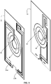
- Figs. 2 and 2a are perspective views showing a detail of the layers 11 and 12 of the target panel 10.
- Fig. 2a is the same as Fig. 2 except that the contact areas are shown using different grey scales.
- the first layer 11 has a central circular conductive first area 20 to which there are connected conductive tracks 20a and 20b that are routed to a contact pad 20c.
- Surrounding the first area 20 is an annular conductive second area 21, which is electrically insulated from the first area 20 and to which there are connected conductive tracks 21a and 21b that are routed to a contact pad 21c.
- annular conductive third area 22 surrounding the second area 21 is an annular conductive third area 22, which is electrically insulated from the second area 21 and to which there are connected conductive tracks 22a and 22b that are routed to a contact pad 22c.
- the contact pads 20c, 21c and 22c are located toward the lower edge of the layer 11 for abutting respective contacts of the hit scoring apparatus as described below with reference to Figs. 5 to 8 of the drawings.
- the target panel 10 is functionally identical to that described in above-mentioned US Patent No. 6,994,347 .
- the second layer 12 has multiple conductive areas denoted by 20', 21' and 22'.
- a central circular conductive first area 20' is routed via conductive tracks 21a' and 21b' to a contact pad 20c'.
- annular conductive second area 21' Surrounding the first area 20' is an annular conductive second area 21', which is electrically insulated from the first area 20' and to which there are connected conductive tracks 21a' and 21b' that are routed to a contact pad 21c'.
- annular conductive third area 22' Surrounding the second area 21' is an annular conductive third area 22', which is electrically insulated from the second area 21' and to which there is connected a conductive track 22a' that is routed to a contact pad 22c'.
- the contact pads 20c', 21c' and 22c' are also located toward the lower edge of the layer 12 for abutting respective contacts of the hit scoring apparatus.
- the first area 20' is also routed via a conductive track 20d' to a conductive area 20e' in a portion of the second layer 12 that is spatially displaced from the central portion 21'.
- the second area 21' is also routed via a conductive track 21d' to a conductive area 21e' proximate and partly surrounding the area 20e'
- the third area 22' is also routed via a conductive track 22d' to a conductive area 22e' proximate and partly surrounding the area 21e'.
- complementary conductive areas 20e, 21e and 22e are provided in overlapping areas of the first layer 11 and are routed to respective contact pads 20c", 21c" and 22c" located toward the lower edge of the layer 12 for abutting respective contacts of the hit scoring apparatus.
- the contact areas 20e, 21e and 22e on the first layer 11 together with the complementary contacts 20e', 21e' and 22e' of the second layer 12 define a generally rectangular portion of the target corresponding to critical anatomical features of the target, which when hit by a bullet are likely to cause significant damage to the victim.
- apertures 25a, 25b and mutually aligned apertures 25a', 25b' shown in Fig. 3 are formed in the first and second layers 11 and 12 respectively, so that when the respective apertures 25a, 25a' and 25b, 25b' are aligned, the two layers 11 and 12 are properly registered.
- the contact pads 20c', 21c' and 22c' on the second layer 12 are clustered together, thereby allowing accessibility to the contacts of the hit scoring apparatus through the single aperture 26 in the first layer 11.
- this is not a requirement and if desired the contact pads on the two layers may be staggered thereby requiring that multiple apertures or gaps be formed in the first layer to provide accessibility to the contact pads of the second layer.
- the bullet penetrates two discrete layers and therefore produces two signals, each indicative of which area it strikes in each layer.
- the apparent ambiguity of where the bullet penetrates the first layer 11 is resolved by the fact that it penetrates the second layer 12 in the annular contact area 21' surround the central area 20. This being the case, the bullet cannot have entered the first layer in the central area 20 even though it is the contact pad 20c connected to the central area 20 in the first layer 11 that senses the short circuit.
- Fig. 4 is a perspective view of the two layers 11 and 12 of the target panel wherein different areas of the target are identified using a matrix, allowing identification of where a bullet strikes the target according to which contacts of the two layers are shorted by the bullet.
- Table 1 Truth Table Contact Pad ID 20c' ( 21c' ( 22c' ( 20c Aa Ab Ac 21c Ba Ab', Ba, B'a x 22c Ca x Ac', ac', ac, B'b, Bb, C'b, Cb 20c" Cd 21c" Cd 22c" Cd
- the target panel 10 operates in conjunction with a custom hit scoring apparatus that will now be described.
- the distinctive features of the target panel per se as comprising a pair of spaced part electrically conductive first and second layers separated by at least one electrically non-conductive layer.
- Each conductive layer has at least two discrete conductive areas routed by respective conductive tracks to separate contact pads on a common edge of the target panel.
- At least one of the conductive tracks in each layer intersects a conductive area in the same layer that is routed by a different conductive track to a different contact pad in the same layer.
- the conductive tracks in each of the conductive layers are arranged such that a portion of a conductive track that intersects a contact area in the first layer does not overlap a portion of a conductive track that intersects a contact area in the second layer.
- the conductive track identified as 20a in Fig. 2 crosses through the discrete areas identified as 21 and 22 in Fig. 2 .
- the conductive track 20a in the first layer 11 cannot overlap or intersect any other conductive track in either of the two layers and specifically not in the second layer 12. This ensures that a possible ambiguity as to which contact area is penetrated by a bullet that pierces a conductive track in one layer is resolved by the certainty as to which contact area is penetrated by the bullet in the other layer.
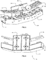
- a clamping device 30 of a hit-scoring apparatus comprising a fixed jaw 31 supporting on a rear surface 32 thereof a plurality of first contacts 33 and second contacts 34.
- the clamping device 30 further includes a movable jaw 35 that is mounted on a pin 36 projecting from the rear surface 32 of the fixed jaw 31 and is biased into an open position as shown in Fig. 5 by a coil spring 37.
- the movable jaw 35 is operated by a handle 38 in manner known per se.
- the fixed jaw 31 is attached to a mounting plate 39 by means of which the clamping device 30 may be supported on a suitable support surface.
- the mounting plate 39 also prevents rotation of the movable jaw 35 about the pin 36, thereby ensuring that the two jaws mate properly when closed. Proper registration between the two jaws is ensured by means of lugs 40, 40' projecting on opposite sides of the fixed jaw 31 which engage complementary apertures 41, 41' in the movable jaw 35.
- the pairs of lugs and apertures ⁇ 40, 41 ⁇ and ⁇ 40', 41' ⁇ are spatially aligned with the respective apertures ⁇ 25a, 25a' ⁇ and ⁇ 25b, 25b' ⁇ of the target panel 30 so that when the target panel 30 is clamped between the two jaws 31 and 35, the contact pads in the target panel make good electrical contact with the respective contacts 33, 34 on the fixed jaw 31.
- Each of the jaws 31 and 35 may consist of three sections: a central section and two lateral sections inclined with respect to the central section at an obtuse angle of about 160°. This requires that the target panel be foldable about vertical creases or that the act of closing the jaws of the clamping device 30 induce the required folding, which increases the rigidity of the target panel. This is important because if steps are not taken to support the rear second layer 12 of the target panel 10, a bullet that penetrates the front first layer 11 may simply push the rear second layer 12 away from the first layer 11, without actually penetrating it. Were this to occur, the bullet would not create the required short-circuit between the two layers by means of which penetration is detected. Nevertheless, it will be appreciated that the required support of the rear second layer 12 may be achieved by other means, such as by mounting a rigid layer behind the second layer 12 or clamping a rigid or semi-rigid panel behind the target panel 10.
- the fixed jaw 31 has a generally hollow housing containing one or more circuit boards 45 (shown in Fig. 7 ) to which proximate contacts 33 or 34 are connected and which contain circuitry for sensing a short-circuit between one of the first contacts 33 and one of the second contacts 34 and producing indication signals indicating which of the first and second contacts were shorted.
- the circuit boards 45 may also contain a processor that is responsive to the indication signals for identifying which area of the target panel was hit. Additionally or alternatively, the circuit boards 45 may be connected to an outlet 46, allowing connection to a remote processor and/or indicator using either a wired or wireless protocol. They may also be connected to a jack socket 47 for connecting an external DC supply.
- the movable jaw 35 which may be formed of an electrically insulating material. This has the benefit that the only connections from the contacts 33 and 34 to the circuit boards 45 are within the fixed jaw 31 and are thus not subjected to movement or strain when opening and closing the clamping device 30.
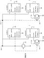
- FIG. 9 showing schematically a detail of a circuit for counting hits and determining possible areas where the target panel is hit.
- the circuit comprises for each pair of contact pads in the two layers e.g. ⁇ 20c, 20c' ⁇ , ⁇ 20c, 21c' ⁇ and so on a discriminator comprising a first timer 50 having an input connected to the corresponding contact pad e.g. 20c in the first layer and a second timer 51 having an input connected to the corresponding contact pad e.g. 20c', 21c' in the second layer.
- the timers 50, 51 may be constituted by an IC circuit in the ubiquitous 555 or 556 families.
- the auxiliary components are not shown in Fig. 9 for ease of description and because use of these ICs is known per se.
- the circuit is powered by a DC power supply 52 that may be a battery inside the fixed jaw or may be derived from an external power supply coupled to the circuit via the DC jack socket 47.
- a normally open electronic switch 53 is connected between each contact pad 20c', 21c', 22c' of the second layer 12 and GND.
- the switch 53 is shown as a NPN bipolar junction transistor although other devices such as opto-couplers may equally well and even preferably employed.
- the base of the transistor is connected to the respective contact, the emitter is connected to GND and the collector is connected to the input (Trigger) of the second timer 51.
- the first timer 50 produces a pulse constituting a first indication signal, which identifies the contact pad in the first layer shorted by the bullet.
- the second timer 51 produces a pulse of shorter duration constituting a second indication signal, which identifies the contact pad in the second layer shorted by the bullet.
- the outputs of all the timers 50, 51 are fed to a processor via a multiplexer neither of which is shown.
- the bullet passes through the target panel so fast that the duration of the short circuit is substantially instantaneous.
- the timers 50, 51 are therefore configured to produce pulses of much longer duration in order to allow the processor sufficient time to scan all of the timers and determine which pair of timers is active. This in turn allows the processor to access a read-only memory in which the Truth Table is stored and thereby determine which contact areas are shorted by the bullet.
- the processor may, of course, be a programmable device that is programmed to compute a cumulative count of hits and to show for each one where the target was hit.
- the processor, its associate memory and other circuitry may be mounted on the circuit board 45 shown in Fig. 7 or it may be coupled thereto via the outlet 46.
- the results of the processor may be output in various ways. For example, they can be shown graphically on a display device coupled to the processor. Alternatively, a dummy target can be coupled to the processor and can have in discrete areas of the target different colored LEDs that are arranged to illuminate and provide a visual record. The cumulative hit count can be displayed on the display device or on a separate dedicated counter.
Landscapes
- Engineering & Computer Science (AREA)
- General Engineering & Computer Science (AREA)
- Aiming, Guidance, Guns With A Light Source, Armor, Camouflage, And Targets (AREA)
- Toys (AREA)
Claims (9)
- Trefferauswertungsvorrichtung zum Schießtraining, umfassend:einen Zielscheibenhalter, der einen Körper aufweist, der eine feste erste Klemmbacke (31) und eine bewegliche zweite Klemmbacke (35) einer Klemmvorrichtung (30) bildet, wobei die erste Klemmbacke (31) und die zweite Klemmbacke (35) elektrisch voneinander isoliert sind;einen Schließmechanismus, um der zweiten Klemmbacke (35) eine im Wesentlichen lineare Bewegung relativ zu der ersten Klemmbacke (31) zu verleihen; undeine Zieltafel (10), die zwischen der ersten (31) und der zweiten (35) Klemmbacke einklemmbar ist, wobei die Zieltafel (10) eine Vielzahl von Schichten aufweist, die eine elektrisch leitende erste Schicht (11) und eine elektrisch leitende zweite Schicht (12) beinhalten, die von der ersten Schicht (11) durch zumindest eine elektrisch nichtleitende Schicht (13) getrennt und beabstandet sind, wobei, wenn die Zieltafel (10) zwischen der ersten (31) und der zweiten (35) Klemmbacke des Zieltafelhalters (30) eingeklemmt ist, separate elektrische Verbindungen zwischen vordefinierten Bereichen (20, 21, 22, 20', 21', 22') jeweils der ersten (11) und der zweiten (12) Schicht und elektrischen Kontakten (33, 34) der ersten Klemmbacke (31) hergestellt werden, wobei die elektrischen Kontakte (33, 34) des Weiteren mit einer Trefferauswertungseinheit verbunden sind;dadurch gekennzeichnet, dass:die erste Klemmbacke (31) auf ihrer Rückseite (32) eine Vielzahl von ersten (33) und zweiten (34) elektrischen Kontakten trägt, von denen zumindest einer der ersten elektrischen Kontakte (33) geeignet ist, mit zumindest einem jeweiligen Bereich (20, 21, 22) der elektrisch leitenden ersten Schicht (11) in Kontakt zu kommen und von denen zumindest zwei zweite elektrische Kontakte (34) geeignet sind, mit jeweiligen Bereichen (20', 21', 22') der elektrisch leitenden zweiten Schicht (12) durch eine oder mehrere jeweilige Öffnungen (25a, 25b) oder Spalte, die in der ersten Schicht (11) ausgebildet sind, in Kontakt zu kommen;jeder der ersten elektrischen Kontakte (33) mit einer Quelle einer Gleichspannung erster Polarität (52) verbunden ist;jeder der zweiten elektrischen Kontakte (34) mit einer Quelle einer Gleichspannung entgegengesetzter zweiter Polarität über einen jeweiligen Schließschalter (53) verbindbar ist, der geeignet ist, sich als Reaktion auf ein Geschoss (15) zu schließen, das zwischen die erste Schicht (11) und die zweite Schicht (12) eindringt, wodurch die Gleichspannung erster Polarität (52) an den jeweiligen Schalter (53) angelegt wird, der mit dem zweiten elektrischen Kontakt (34) verbunden ist;eine jeweilige erste Anzeige mit jedem der ersten elektrischen Kontakte (33) verbunden ist und auf das Schließen des Schalters (53) anspricht, um ein erstes Signal zu erzeugen, das einen Bereich (20, 21, 22) in der ersten Schicht (11) anzeigt, der von dem Geschoss (15) getroffen wurde; eine jeweilige zweite Anzeige mit jedem Schalter (53) verbunden ist und auf das Schließen des Schalters (53) anspricht, um ein zweites Signal zu erzeugen, das einen Bereich (20', 21', 22') in der zweiten Schicht (12) anzeigt, der von dem Geschoss (15) getroffen wurde; unddie Trefferauswertungseinheit mit jeder der ersten Anzeigen und mit jeder der zweiten Anzeigen gekoppelt ist und auf die jeweiligen ersten und zweiten Signale anspricht, um einen Bereich des Ziels zu bestimmen, der gemeinsam mit den jeweiligen ersten (33) und zweiten (34) elektrischen Kontakten verbunden ist.
- Vorrichtung nach Anspruch 1, wobei die feststehende Klemmbacke (31) des Weiteren längliche Ansätze (40, 40') umfasst, die von einander gegenüberliegenden Seiten der Klemmbacke (31) vorstehen und an diesen fest angebracht sind, wobei die Ansätze (40, 40') mit komplementär geformten Öffnungen (25a, 25a', 25b, 25b') im unteren Teil der Zieltafel (10) übereinstimmen und in diese eingreifen.
- Vorrichtung nach Anspruch 2, wobei die bewegliche Klemmbacke (35) Öffnungen (41, 41") aufweist, die mit den Nasen (40, 40') in der festen Klemmbacke (31) übereinstimmen und diese aufnehmen.
- Vorrichtung nach einem der vorangegangenen Ansprüche, wobei jede der Klemmbacken (31, 35) einen mittleren Abschnitt und zwei seitliche Abschnitte, welche in Bezug auf den mittleren Abschnitt in einem stumpfen Winkel geneigt sind, umfasst, und wobei die Zieltafel (10) mit zwei sich in Längsrichtung erstreckenden Falten versehen ist, die der Zieltafel (10) eine Querschnittsform verleihen, die einem Spalt zwischen der festen Klemmbacke (31) und der beweglichen Klemmbacke (35) entspricht.
- Vorrichtung nach einem der vorangegangenen Ansprüche, wobei der Verschlussmechanismus einen selbstsichernden Kniehebelspannmechanismus beinhaltet.
- Vorrichtung nach einem der vorangegangenen Ansprüche, wobei die erste Anzeige einen Zeitgeber (50) zur Erzeugung des ersten Signals von ausreichender Dauer beinhaltet, damit die Trefferauswertungseinheit alle ersten und zweiten Anzeigen abtasten kann, um festzustellen, welche aktiv sind.
- Vorrichtung nach einem der vorangegangenen Ansprüche, wobei die zweite Anzeige einen Zeitgeber (51) beinhaltet, der über den Schließschalter (53) mit der jeweiligen Kontaktfläche in der zweiten Schicht (12) gekoppelt ist, wobei der Zeitgeber (51) so eingerichtet ist, dass er das zweite Signal von ausreichender Dauer erzeugt, damit die Trefferauswertungseinheit alle zweiten Anzeigen abtasten kann, um zu bestimmen, welche aktiv ist.
- Vorrichtung nach einem der vorangegangenen Ansprüche, wobei der Schließschalter (53) ein Optokoppler oder ein Transistor ist.
- Vorrichtung nach einem der vorangegangenen Ansprüche, des Weiteren aufweisend einen Prozessor, der funktionsmäßig mit jeder ersten Anzeige und jeder zweiten Anzeige gekoppelt ist und eingerichtet ist, um auf einen Speicher zuzugreifen, der Daten speichert, die diskrete Kontaktbereiche den jeweiligen Kontaktflächen in den beiden Schichten (11, 12) zuordnen.
Applications Claiming Priority (2)
| Application Number | Priority Date | Filing Date | Title |
|---|---|---|---|
| IL243602A IL243602A0 (en) | 2016-01-13 | 2016-01-13 | Device for hitting stock and target board in shooting practice |
| PCT/US2017/013026 WO2017123638A1 (en) | 2016-01-13 | 2017-01-11 | Hit-scoring apparatus and target panel for shooting practice |
Publications (3)
| Publication Number | Publication Date |
|---|---|
| EP3403045A1 EP3403045A1 (de) | 2018-11-21 |
| EP3403045A4 EP3403045A4 (de) | 2019-10-30 |
| EP3403045B1 true EP3403045B1 (de) | 2022-08-10 |
Family
ID=57300913
Family Applications (1)
| Application Number | Title | Priority Date | Filing Date |
|---|---|---|---|
| EP17738861.8A Active EP3403045B1 (de) | 2016-01-13 | 2017-01-11 | Trefferpunktevorrichtung für schiessübungen |
Country Status (6)
| Country | Link |
|---|---|
| US (1) | US10670377B2 (de) |
| EP (1) | EP3403045B1 (de) |
| CN (2) | CN108463687B (de) |
| CA (1) | CA3008962C (de) |
| IL (1) | IL243602A0 (de) |
| WO (1) | WO2017123638A1 (de) |
Families Citing this family (2)
| Publication number | Priority date | Publication date | Assignee | Title |
|---|---|---|---|---|
| US12480747B2 (en) * | 2020-02-10 | 2025-11-25 | Plan Alpha Ltd. | Circuitry to detect difference between lead line and target hits |
| CN113587731A (zh) * | 2021-08-02 | 2021-11-02 | 中弓(江苏)智能设备有限公司 | 射击显示精度提高四倍的电子靶标 |
Family Cites Families (25)
| Publication number | Priority date | Publication date | Assignee | Title |
|---|---|---|---|---|
| CH487388A (de) * | 1968-01-19 | 1970-03-15 | Schaerz Armin | Schiess-Scheibe zum Beschiessen mit Geschossen aus Schusswaffen |
| CH479852A (fr) * | 1966-05-03 | 1969-10-15 | Polytronic S A | Installation de tir comprenant une cible et un dispositif d'indication automatique du résultat d'un coup tiré sur la cible |
| GB1260671A (en) * | 1968-02-08 | 1972-01-19 | Australasian Training Aids Pty | Improvements relating to target apparatus |
| US4129299A (en) | 1977-02-11 | 1978-12-12 | Caswell Equipment Company | Apparatus for hit scoring targets |
| EP0185877B1 (de) * | 1984-10-30 | 1990-04-18 | Carlheinz Geuss | Zieleinrichtung für Infrarot-Schiessübungen |
| IL75848A0 (en) * | 1985-07-19 | 1985-11-29 | Hadas Azarei Hadracha B M | Hit-scoring shooting target |
| US4786058A (en) * | 1987-06-22 | 1988-11-22 | Baughman James S | Electric target and display |
| US4946171A (en) * | 1989-01-03 | 1990-08-07 | Eastman Kodak Company | Live fire target modular support structure |
| US5193816A (en) * | 1992-04-01 | 1993-03-16 | Joanell Laboratories, Inc. | Projectile and target identifying apparatus |
| US5486007A (en) * | 1994-05-09 | 1996-01-23 | High Flyte International Ltd. | Automated dart board |
| CN2414382Y (zh) * | 2000-02-25 | 2001-01-10 | 刘建中 | 一种实弹射击自动报靶装置 |
| IL148561A (en) * | 2002-03-07 | 2006-08-20 | Mordechai Tessel | Hit-scoring apparatus for shooting practice |
| US20040036221A1 (en) | 2002-08-22 | 2004-02-26 | Martinez Dan L. | Shooting target with electronic zone indicators and method of use |
| CN2771801Y (zh) * | 2005-02-28 | 2006-04-12 | 邵学旺 | 一种用于飞镖电子靶的记分感应电路板 |
| CN201062936Y (zh) * | 2007-02-15 | 2008-05-21 | 凌阳科技股份有限公司 | 电子飞镖靶和电子飞镖装置 |
| CN101105384A (zh) * | 2007-07-04 | 2008-01-16 | 卓钰富 | 微电脑的搭扣式电子靶体 |
| US8047546B1 (en) * | 2007-08-01 | 2011-11-01 | Meggitt Training Systems, Inc. | Multi-target clamping assembly |
| US20090127790A1 (en) * | 2007-11-20 | 2009-05-21 | Chun-Ling Chao | Electronic target device |
| US20090194943A1 (en) * | 2008-01-31 | 2009-08-06 | Amitai Peretz | Hit scoring target operable by an electromagnetic signature detector |
| CN201340234Y (zh) * | 2009-01-05 | 2009-11-04 | 梁国栋 | 一种具有自我恢复力的报靶靶标 |
| CN201387833Y (zh) * | 2009-03-17 | 2010-01-20 | 王金和 | 一种用于移动式电子靶的线路薄膜开关 |
| CN201392147Y (zh) * | 2009-04-08 | 2010-01-27 | 梁国栋 | 改进型具有自我恢复力的报靶靶标 |
| KR101319159B1 (ko) * | 2009-08-25 | 2013-10-17 | 주식회사 홍인터내셔날 | 다트 게임 장치 및 다트 게임 장치의 게임 데이터 인증 방법 |
| CN201740469U (zh) * | 2010-07-16 | 2011-02-09 | 昆明理工大学 | 一种电子靶面传感器 |
| CN105135950B (zh) * | 2015-05-22 | 2016-08-17 | 合肥君信电子科技有限公司 | 一种靶纸定位装置以及应用该装置的靶纸定位方法 |
-
2016
- 2016-01-13 IL IL243602A patent/IL243602A0/en active IP Right Grant
-
2017
- 2017-01-11 CN CN201780006398.1A patent/CN108463687B/zh not_active Expired - Fee Related
- 2017-01-11 US US16/068,100 patent/US10670377B2/en active Active
- 2017-01-11 CA CA3008962A patent/CA3008962C/en active Active
- 2017-01-11 WO PCT/US2017/013026 patent/WO2017123638A1/en not_active Ceased
- 2017-01-11 EP EP17738861.8A patent/EP3403045B1/de active Active
- 2017-01-11 CN CN202010661583.8A patent/CN111879181B/zh not_active Expired - Fee Related
Also Published As
| Publication number | Publication date |
|---|---|
| IL243602A0 (en) | 2016-07-31 |
| EP3403045A1 (de) | 2018-11-21 |
| US10670377B2 (en) | 2020-06-02 |
| CA3008962C (en) | 2022-05-31 |
| CN108463687B (zh) | 2020-07-17 |
| WO2017123638A1 (en) | 2017-07-20 |
| CN111879181B (zh) | 2023-06-20 |
| CN108463687A (zh) | 2018-08-28 |
| CN111879181A (zh) | 2020-11-03 |
| US20190025017A1 (en) | 2019-01-24 |
| EP3403045A4 (de) | 2019-10-30 |
| CA3008962A1 (en) | 2017-07-20 |
Similar Documents
| Publication | Publication Date | Title |
|---|---|---|
| EP2741064A2 (de) | Kapazitiver Berührungssensor | |
| EP4242808A3 (de) | Berührungssensor und anzeigevorrichtung | |
| US11617236B2 (en) | Induction hob and method for controlling an induction hob | |
| US10670377B2 (en) | Hit-scoring apparatus and target panel for shooting practice | |
| ATE335984T1 (de) | Ziel mit trefferanzeige für schiessübungen | |
| GB0301242D0 (en) | A tool holder arrangement | |
| US20170172851A1 (en) | Device For Detecting The Removal Of Drugs | |
| TW201101686A (en) | Proximity sensor and revolution operation detecting device | |
| US20160247655A1 (en) | Target and/or filament for an x-ray tube, x-ray tube, method for identifying a target and/or a filament and method for setting the characteristics of a target and/or a filament | |
| US10895657B2 (en) | Apparatus and methods for obscured feature detection with uniform electric fields | |
| BR112017028006B1 (pt) | Sensor de folga e método de medição de folga | |
| US20090160470A1 (en) | Semiconductor and method | |
| US20200284558A1 (en) | Hit-scoring apparatus and target panel for shooting practice | |
| US4477860A (en) | Electrode array | |
| ES2976788T3 (es) | Dispositivo receptáculo y procedimiento de identificación de elementos de trabajo | |
| KR101870517B1 (ko) | 온도 제어 기능이 향상된 유도 가열 기기 | |
| US9476781B2 (en) | Sensor device and deposition device having a sensor device | |
| CN210387930U (zh) | 一种超声波焊接设备 | |
| CN203732663U (zh) | 金手指检测装置 | |
| JP2002062105A (ja) | ヘッド分離型センサ、静電容量式センサ及びウエハ検出装置 | |
| US20260086202A1 (en) | Laser ranging device | |
| CN116821980A (zh) | 一种置零模块及加密服务器 | |
| RS63358B1 (sr) | Infracrveni termometar koji može da promeni režim merenja temperature čela i režim merenja temperature uha i postupak promene | |
| TWI385503B (zh) | 檢測儀 | |
| CN105353188A (zh) | 变压器电阻测试仪外部结构 |
Legal Events
| Date | Code | Title | Description |
|---|---|---|---|
| STAA | Information on the status of an ep patent application or granted ep patent |
Free format text: STATUS: THE INTERNATIONAL PUBLICATION HAS BEEN MADE |
|
| PUAI | Public reference made under article 153(3) epc to a published international application that has entered the european phase |
Free format text: ORIGINAL CODE: 0009012 |
|
| STAA | Information on the status of an ep patent application or granted ep patent |
Free format text: STATUS: REQUEST FOR EXAMINATION WAS MADE |
|
| 17P | Request for examination filed |
Effective date: 20180801 |
|
| AK | Designated contracting states |
Kind code of ref document: A1 Designated state(s): AL AT BE BG CH CY CZ DE DK EE ES FI FR GB GR HR HU IE IS IT LI LT LU LV MC MK MT NL NO PL PT RO RS SE SI SK SM TR |
|
| AX | Request for extension of the european patent |
Extension state: BA ME |
|
| DAV | Request for validation of the european patent (deleted) | ||
| DAX | Request for extension of the european patent (deleted) | ||
| RIC1 | Information provided on ipc code assigned before grant |
Ipc: F41J 5/048 20060101ALI20190617BHEP Ipc: F41J 1/10 20060101AFI20190617BHEP |
|
| A4 | Supplementary search report drawn up and despatched |
Effective date: 20190926 |
|
| RIC1 | Information provided on ipc code assigned before grant |
Ipc: F41J 5/048 20060101ALI20190920BHEP Ipc: F41J 1/10 20060101AFI20190920BHEP |
|
| STAA | Information on the status of an ep patent application or granted ep patent |
Free format text: STATUS: EXAMINATION IS IN PROGRESS |
|
| 17Q | First examination report despatched |
Effective date: 20210319 |
|
| GRAP | Despatch of communication of intention to grant a patent |
Free format text: ORIGINAL CODE: EPIDOSNIGR1 |
|
| STAA | Information on the status of an ep patent application or granted ep patent |
Free format text: STATUS: GRANT OF PATENT IS INTENDED |
|
| INTG | Intention to grant announced |
Effective date: 20220310 |
|
| GRAS | Grant fee paid |
Free format text: ORIGINAL CODE: EPIDOSNIGR3 |
|
| GRAA | (expected) grant |
Free format text: ORIGINAL CODE: 0009210 |
|
| STAA | Information on the status of an ep patent application or granted ep patent |
Free format text: STATUS: THE PATENT HAS BEEN GRANTED |
|
| AK | Designated contracting states |
Kind code of ref document: B1 Designated state(s): AL AT BE BG CH CY CZ DE DK EE ES FI FR GB GR HR HU IE IS IT LI LT LU LV MC MK MT NL NO PL PT RO RS SE SI SK SM TR |
|
| REG | Reference to a national code |
Ref country code: AT Ref legal event code: REF Ref document number: 1510852 Country of ref document: AT Kind code of ref document: T Effective date: 20220815 Ref country code: CH Ref legal event code: EP |
|
| REG | Reference to a national code |
Ref country code: IE Ref legal event code: FG4D |
|
| REG | Reference to a national code |
Ref country code: DE Ref legal event code: R096 Ref document number: 602017060496 Country of ref document: DE |
|
| REG | Reference to a national code |
Ref country code: SE Ref legal event code: TRGR |
|
| REG | Reference to a national code |
Ref country code: NL Ref legal event code: MP Effective date: 20220810 |
|
| REG | Reference to a national code |
Ref country code: SK Ref legal event code: T3 Ref document number: E 40716 Country of ref document: SK |
|
| REG | Reference to a national code |
Ref country code: LT Ref legal event code: MG9D |
|
| PG25 | Lapsed in a contracting state [announced via postgrant information from national office to epo] |
Ref country code: RS Free format text: LAPSE BECAUSE OF FAILURE TO SUBMIT A TRANSLATION OF THE DESCRIPTION OR TO PAY THE FEE WITHIN THE PRESCRIBED TIME-LIMIT Effective date: 20220810 Ref country code: PT Free format text: LAPSE BECAUSE OF FAILURE TO SUBMIT A TRANSLATION OF THE DESCRIPTION OR TO PAY THE FEE WITHIN THE PRESCRIBED TIME-LIMIT Effective date: 20221212 Ref country code: NO Free format text: LAPSE BECAUSE OF FAILURE TO SUBMIT A TRANSLATION OF THE DESCRIPTION OR TO PAY THE FEE WITHIN THE PRESCRIBED TIME-LIMIT Effective date: 20221110 Ref country code: NL Free format text: LAPSE BECAUSE OF FAILURE TO SUBMIT A TRANSLATION OF THE DESCRIPTION OR TO PAY THE FEE WITHIN THE PRESCRIBED TIME-LIMIT Effective date: 20220810 Ref country code: LV Free format text: LAPSE BECAUSE OF FAILURE TO SUBMIT A TRANSLATION OF THE DESCRIPTION OR TO PAY THE FEE WITHIN THE PRESCRIBED TIME-LIMIT Effective date: 20220810 Ref country code: LT Free format text: LAPSE BECAUSE OF FAILURE TO SUBMIT A TRANSLATION OF THE DESCRIPTION OR TO PAY THE FEE WITHIN THE PRESCRIBED TIME-LIMIT Effective date: 20220810 Ref country code: FI Free format text: LAPSE BECAUSE OF FAILURE TO SUBMIT A TRANSLATION OF THE DESCRIPTION OR TO PAY THE FEE WITHIN THE PRESCRIBED TIME-LIMIT Effective date: 20220810 |
|
| REG | Reference to a national code |
Ref country code: AT Ref legal event code: MK05 Ref document number: 1510852 Country of ref document: AT Kind code of ref document: T Effective date: 20220810 |
|
| PG25 | Lapsed in a contracting state [announced via postgrant information from national office to epo] |
Ref country code: PL Free format text: LAPSE BECAUSE OF FAILURE TO SUBMIT A TRANSLATION OF THE DESCRIPTION OR TO PAY THE FEE WITHIN THE PRESCRIBED TIME-LIMIT Effective date: 20220810 Ref country code: IS Free format text: LAPSE BECAUSE OF FAILURE TO SUBMIT A TRANSLATION OF THE DESCRIPTION OR TO PAY THE FEE WITHIN THE PRESCRIBED TIME-LIMIT Effective date: 20221210 Ref country code: HR Free format text: LAPSE BECAUSE OF FAILURE TO SUBMIT A TRANSLATION OF THE DESCRIPTION OR TO PAY THE FEE WITHIN THE PRESCRIBED TIME-LIMIT Effective date: 20220810 Ref country code: GR Free format text: LAPSE BECAUSE OF FAILURE TO SUBMIT A TRANSLATION OF THE DESCRIPTION OR TO PAY THE FEE WITHIN THE PRESCRIBED TIME-LIMIT Effective date: 20221111 |
|
| PG25 | Lapsed in a contracting state [announced via postgrant information from national office to epo] |
Ref country code: SM Free format text: LAPSE BECAUSE OF FAILURE TO SUBMIT A TRANSLATION OF THE DESCRIPTION OR TO PAY THE FEE WITHIN THE PRESCRIBED TIME-LIMIT Effective date: 20220810 Ref country code: RO Free format text: LAPSE BECAUSE OF FAILURE TO SUBMIT A TRANSLATION OF THE DESCRIPTION OR TO PAY THE FEE WITHIN THE PRESCRIBED TIME-LIMIT Effective date: 20220810 Ref country code: ES Free format text: LAPSE BECAUSE OF FAILURE TO SUBMIT A TRANSLATION OF THE DESCRIPTION OR TO PAY THE FEE WITHIN THE PRESCRIBED TIME-LIMIT Effective date: 20220810 Ref country code: DK Free format text: LAPSE BECAUSE OF FAILURE TO SUBMIT A TRANSLATION OF THE DESCRIPTION OR TO PAY THE FEE WITHIN THE PRESCRIBED TIME-LIMIT Effective date: 20220810 Ref country code: CZ Free format text: LAPSE BECAUSE OF FAILURE TO SUBMIT A TRANSLATION OF THE DESCRIPTION OR TO PAY THE FEE WITHIN THE PRESCRIBED TIME-LIMIT Effective date: 20220810 Ref country code: AT Free format text: LAPSE BECAUSE OF FAILURE TO SUBMIT A TRANSLATION OF THE DESCRIPTION OR TO PAY THE FEE WITHIN THE PRESCRIBED TIME-LIMIT Effective date: 20220810 |
|
| PGFP | Annual fee paid to national office [announced via postgrant information from national office to epo] |
Ref country code: CH Payment date: 20230111 Year of fee payment: 7 |
|
| REG | Reference to a national code |
Ref country code: DE Ref legal event code: R097 Ref document number: 602017060496 Country of ref document: DE |
|
| PG25 | Lapsed in a contracting state [announced via postgrant information from national office to epo] |
Ref country code: EE Free format text: LAPSE BECAUSE OF FAILURE TO SUBMIT A TRANSLATION OF THE DESCRIPTION OR TO PAY THE FEE WITHIN THE PRESCRIBED TIME-LIMIT Effective date: 20220810 |
|
| PGFP | Annual fee paid to national office [announced via postgrant information from national office to epo] |
Ref country code: SK Payment date: 20230109 Year of fee payment: 7 Ref country code: SE Payment date: 20230119 Year of fee payment: 7 Ref country code: GB Payment date: 20230119 Year of fee payment: 7 Ref country code: DE Payment date: 20230123 Year of fee payment: 7 |
|
| PLBE | No opposition filed within time limit |
Free format text: ORIGINAL CODE: 0009261 |
|
| STAA | Information on the status of an ep patent application or granted ep patent |
Free format text: STATUS: NO OPPOSITION FILED WITHIN TIME LIMIT |
|
| PG25 | Lapsed in a contracting state [announced via postgrant information from national office to epo] |
Ref country code: AL Free format text: LAPSE BECAUSE OF FAILURE TO SUBMIT A TRANSLATION OF THE DESCRIPTION OR TO PAY THE FEE WITHIN THE PRESCRIBED TIME-LIMIT Effective date: 20220810 |
|
| 26N | No opposition filed |
Effective date: 20230511 |
|
| PG25 | Lapsed in a contracting state [announced via postgrant information from national office to epo] |
Ref country code: SI Free format text: LAPSE BECAUSE OF FAILURE TO SUBMIT A TRANSLATION OF THE DESCRIPTION OR TO PAY THE FEE WITHIN THE PRESCRIBED TIME-LIMIT Effective date: 20220810 |
|
| PG25 | Lapsed in a contracting state [announced via postgrant information from national office to epo] |
Ref country code: LU Free format text: LAPSE BECAUSE OF NON-PAYMENT OF DUE FEES Effective date: 20230111 |
|
| REG | Reference to a national code |
Ref country code: BE Ref legal event code: MM Effective date: 20230131 |
|
| PG25 | Lapsed in a contracting state [announced via postgrant information from national office to epo] |
Ref country code: FR Free format text: LAPSE BECAUSE OF NON-PAYMENT OF DUE FEES Effective date: 20230131 Ref country code: BE Free format text: LAPSE BECAUSE OF NON-PAYMENT OF DUE FEES Effective date: 20230131 |
|
| PG25 | Lapsed in a contracting state [announced via postgrant information from national office to epo] |
Ref country code: IE Free format text: LAPSE BECAUSE OF NON-PAYMENT OF DUE FEES Effective date: 20230111 |
|
| PG25 | Lapsed in a contracting state [announced via postgrant information from national office to epo] |
Ref country code: IT Free format text: LAPSE BECAUSE OF FAILURE TO SUBMIT A TRANSLATION OF THE DESCRIPTION OR TO PAY THE FEE WITHIN THE PRESCRIBED TIME-LIMIT Effective date: 20220810 |
|
| PG25 | Lapsed in a contracting state [announced via postgrant information from national office to epo] |
Ref country code: MC Free format text: LAPSE BECAUSE OF FAILURE TO SUBMIT A TRANSLATION OF THE DESCRIPTION OR TO PAY THE FEE WITHIN THE PRESCRIBED TIME-LIMIT Effective date: 20220810 |
|
| PG25 | Lapsed in a contracting state [announced via postgrant information from national office to epo] |
Ref country code: MC Free format text: LAPSE BECAUSE OF FAILURE TO SUBMIT A TRANSLATION OF THE DESCRIPTION OR TO PAY THE FEE WITHIN THE PRESCRIBED TIME-LIMIT Effective date: 20220810 |
|
| REG | Reference to a national code |
Ref country code: DE Ref legal event code: R119 Ref document number: 602017060496 Country of ref document: DE |
|
| REG | Reference to a national code |
Ref country code: SK Ref legal event code: MM4A Ref document number: E 40716 Country of ref document: SK Effective date: 20240111 |
|
| REG | Reference to a national code |
Ref country code: CH Ref legal event code: PL |
|
| REG | Reference to a national code |
Ref country code: SE Ref legal event code: EUG |
|
| GBPC | Gb: european patent ceased through non-payment of renewal fee |
Effective date: 20240111 |
|
| PG25 | Lapsed in a contracting state [announced via postgrant information from national office to epo] |
Ref country code: DE Free format text: LAPSE BECAUSE OF NON-PAYMENT OF DUE FEES Effective date: 20240801 |
|
| PG25 | Lapsed in a contracting state [announced via postgrant information from national office to epo] |
Ref country code: GB Free format text: LAPSE BECAUSE OF NON-PAYMENT OF DUE FEES Effective date: 20240111 |
|
| PG25 | Lapsed in a contracting state [announced via postgrant information from national office to epo] |
Ref country code: CH Free format text: LAPSE BECAUSE OF NON-PAYMENT OF DUE FEES Effective date: 20240131 |
|
| PG25 | Lapsed in a contracting state [announced via postgrant information from national office to epo] |
Ref country code: SK Free format text: LAPSE BECAUSE OF NON-PAYMENT OF DUE FEES Effective date: 20240111 |
|
| PG25 | Lapsed in a contracting state [announced via postgrant information from national office to epo] |
Ref country code: SK Free format text: LAPSE BECAUSE OF NON-PAYMENT OF DUE FEES Effective date: 20240111 Ref country code: GB Free format text: LAPSE BECAUSE OF NON-PAYMENT OF DUE FEES Effective date: 20240111 Ref country code: DE Free format text: LAPSE BECAUSE OF NON-PAYMENT OF DUE FEES Effective date: 20240801 Ref country code: CH Free format text: LAPSE BECAUSE OF NON-PAYMENT OF DUE FEES Effective date: 20240131 |
|
| PG25 | Lapsed in a contracting state [announced via postgrant information from national office to epo] |
Ref country code: BG Free format text: LAPSE BECAUSE OF FAILURE TO SUBMIT A TRANSLATION OF THE DESCRIPTION OR TO PAY THE FEE WITHIN THE PRESCRIBED TIME-LIMIT Effective date: 20220810 |
|
| PG25 | Lapsed in a contracting state [announced via postgrant information from national office to epo] |
Ref country code: BG Free format text: LAPSE BECAUSE OF FAILURE TO SUBMIT A TRANSLATION OF THE DESCRIPTION OR TO PAY THE FEE WITHIN THE PRESCRIBED TIME-LIMIT Effective date: 20220810 |
|
| PG25 | Lapsed in a contracting state [announced via postgrant information from national office to epo] |
Ref country code: CY Free format text: LAPSE BECAUSE OF FAILURE TO SUBMIT A TRANSLATION OF THE DESCRIPTION OR TO PAY THE FEE WITHIN THE PRESCRIBED TIME-LIMIT; INVALID AB INITIO Effective date: 20170111 |
|
| PG25 | Lapsed in a contracting state [announced via postgrant information from national office to epo] |
Ref country code: HU Free format text: LAPSE BECAUSE OF FAILURE TO SUBMIT A TRANSLATION OF THE DESCRIPTION OR TO PAY THE FEE WITHIN THE PRESCRIBED TIME-LIMIT; INVALID AB INITIO Effective date: 20170111 |
|
| PG25 | Lapsed in a contracting state [announced via postgrant information from national office to epo] |
Ref country code: SE Free format text: LAPSE BECAUSE OF NON-PAYMENT OF DUE FEES Effective date: 20240112 |
|
| PG25 | Lapsed in a contracting state [announced via postgrant information from national office to epo] |
Ref country code: TR Free format text: LAPSE BECAUSE OF FAILURE TO SUBMIT A TRANSLATION OF THE DESCRIPTION OR TO PAY THE FEE WITHIN THE PRESCRIBED TIME-LIMIT Effective date: 20220810 |