EP3403444B1 - Entdeckungssignalblock-mapping - Google Patents
Entdeckungssignalblock-mapping Download PDFInfo
- Publication number
- EP3403444B1 EP3403444B1 EP16804750.4A EP16804750A EP3403444B1 EP 3403444 B1 EP3403444 B1 EP 3403444B1 EP 16804750 A EP16804750 A EP 16804750A EP 3403444 B1 EP3403444 B1 EP 3403444B1
- Authority
- EP
- European Patent Office
- Prior art keywords
- group
- discovery signaling
- mapping
- blocks
- dsb
- Prior art date
- Legal status (The legal status is an assumption and is not a legal conclusion. Google has not performed a legal analysis and makes no representation as to the accuracy of the status listed.)
- Active
Links
Images





Classifications
-
- H—ELECTRICITY
- H04—ELECTRIC COMMUNICATION TECHNIQUE
- H04W—WIRELESS COMMUNICATION NETWORKS
- H04W72/00—Local resource management
- H04W72/04—Wireless resource allocation
- H04W72/044—Wireless resource allocation based on the type of the allocated resource
- H04W72/0446—Resources in time domain, e.g. slots or frames
-
- H—ELECTRICITY
- H04—ELECTRIC COMMUNICATION TECHNIQUE
- H04L—TRANSMISSION OF DIGITAL INFORMATION, e.g. TELEGRAPHIC COMMUNICATION
- H04L5/00—Arrangements affording multiple use of the transmission path
- H04L5/003—Arrangements for allocating sub-channels of the transmission path
- H04L5/0053—Allocation of signalling, i.e. of overhead other than pilot signals
-
- H—ELECTRICITY
- H04—ELECTRIC COMMUNICATION TECHNIQUE
- H04W—WIRELESS COMMUNICATION NETWORKS
- H04W48/00—Access restriction; Network selection; Access point selection
- H04W48/08—Access restriction or access information delivery, e.g. discovery data delivery
- H04W48/12—Access restriction or access information delivery, e.g. discovery data delivery using downlink control channel
-
- H—ELECTRICITY
- H04—ELECTRIC COMMUNICATION TECHNIQUE
- H04W—WIRELESS COMMUNICATION NETWORKS
- H04W48/00—Access restriction; Network selection; Access point selection
- H04W48/16—Discovering, processing access restriction or access information
-
- H—ELECTRICITY
- H04—ELECTRIC COMMUNICATION TECHNIQUE
- H04W—WIRELESS COMMUNICATION NETWORKS
- H04W72/00—Local resource management
- H04W72/12—Wireless traffic scheduling
- H04W72/1263—Mapping of traffic onto schedule, e.g. scheduled allocation or multiplexing of flows
Definitions
- aspects of the disclosure generally relate to wireless or mobile communications networks, such as, but not limited to, the Universal Mobile Telecommunications System (UMTS) Terrestrial Radio Access Network (UTRAN), Long Term Evolution (LTE) Evolved UTRAN (E-UTRAN), LTE-Advanced (LTE-A), 5 th generation (5G) radio access technology, and/or High Speed Packet Access (HSPA).
- UMTS Universal Mobile Telecommunications System
- UTRAN Long Term Evolution
- E-UTRAN Long Term Evolution Evolved UTRAN
- LTE-A LTE-Advanced
- 5G 5 th generation
- HSPA High Speed Packet Access
- some aspects may relate to frame structures for 5G cellular systems.
- Some aspects relate to discovery signal block mapping.
- Universal Mobile Telecommunications System (UMTS) Terrestrial Radio Access Network refers to a communications network including base stations, or Node Bs, and for example radio network controllers (RNC).
- UTRAN allows for connectivity between the user equipment (UE) and the core network.
- the RNC provides control functionalities for one or more Node Bs.
- the RNC and its corresponding Node Bs are called the Radio Network Subsystem (RNS).
- RNC Radio Network Subsystem
- E-UTRAN enhanced UTRAN
- no RNC exists and radio access functionality is provided in the evolved Node B (eNodeB or eNB) or many eNBs. Multiple eNBs may be involved for a single UE connection, for example, in case of Coordinated Multipoint Transmission (CoMP) and in dual connectivity.
- CoMP Coordinated Multipoint Transmission
- LTE Long Term Evolution
- E-UTRAN provides a new radio access technology and refers to the improvements of UMTS through improved efficiency and services, lower costs, and use of new spectrum opportunities.
- LTE is a 3GPP standard that provides for uplink peak rates of at least, for example, 75 megabits per second (Mbps) per carrier and downlink peak rates of at least, for example, 300 Mbps per carrier.
- LTE supports scalable carrier bandwidths from 20 MHz down to 1.4 MHz and supports both Frequency Division Duplexing (FDD) and Time Division Duplexing (TDD).
- FDD Frequency Division Duplexing
- TDD Time Division Duplexing
- LTE may also improve spectral efficiency in networks, allowing carriers to provide more data and voice services over a given bandwidth. Therefore, LTE is designed to fulfill the needs for high-speed data and media transport in addition to high-capacity voice support. Advantages of LTE include, for example, high throughput, low latency, FDD and TDD support in the same platform, an improved end-user experience, and a simple architecture resulting in low operating costs.
- LTE-A LTE-Advanced
- LTE-A is directed toward extending and optimizing the 3GPP LTE radio access technologies.
- a goal of LTE-A is to provide significantly enhanced services by means of higher data rates and lower latency with reduced cost.
- LTE-A is a more optimized radio system fulfilling the international telecommunication union-radio (ITU-R) requirements for IMT-Advanced while keeping the backward compatibility.
- ITU-R international telecommunication union-radio
- LTE Long Term Evolution
- PSS primary synchronization signal
- SSS secondary synchronization signal
- 5G 5th generation mobile networks refers to the new generation of radio systems and network architecture delivering extreme broadband and ultra-robust, low latency network connectivity.
- 5G networks are expected to support data rates of several tens of megabits per second for tens of thousands of users, to support several hundreds of thousands of simultaneous connections for massive sensor deployments, to significantly enhance spectral efficiency compared to LTE, to improve coverage, to enhance signaling efficiency, and to significantly reduce latency compared to LTE.
- WO2015/115376A1 describes a user apparatus configured to communicate with a base station in a radio communication system including a base station and the user apparatus, including: first reference signal reception means configured to measure a received power of first reference signals, transmitted from the base station, that are associated with a plurality of different identifiers, and to select a specific first reference signal; report means configured to report an identifier and a received power of the first reference signal selected by the first reference signal reception means to the base station or a macro cell base station; second reference signal reception means configured to receive a plurality of second reference signals transmitted from the base station; and measurement means configured to measure a reception quality of the second reference signals received by the second reference signal reception means, and to transmit feedback information based on the reception quality to the base station.
- first reference signal reception means configured to measure a received power of first reference signals, transmitted from the base station, that are associated with a plurality of different identifiers, and to select a specific first reference signal
- report means configured to report an identifier and a received power of
- Certain aspects relate to frame structures for 5G cellular systems.
- 5G systems are expected to utilize a wide variety of different transceiver architectures that may range from low digital degree hybrid transceiver architectures to full digital solutions.
- Fig. 1 illustrates an example of a general framework for radio architecture.
- one transmitter unit TXU
- TXRU transceiver unit
- the mapping may be either sub-array or full connection.
- one TXRU is connected to subset of antenna elements where different subsets are disjoint; while in the full connection model, each TXRU is connected to each antenna element.
- Radio distribution network performs antenna virtualization in the radio frequency (RF) domain. Virtualization is not frequency selective but common to resource elements (REs) and signals. RDN may utilize either sub array or full connection mapping between TXRUs and Antenna Elements.
- TXU In the transmitting direction, M antenna ports feed K TXRUs, and K TXRUs feed L antenna elements where M ⁇ K ⁇ L.
- Complexity and power consumption of baseband processing and analog/digital (A/D) conversion likely limits the number of antenna ports M and TXRUs K to be much less than L in the centimetre/millimetre wave (cmWave/mmWave) system where L can be from tens up to hundreds (or even thousands).
- Power consumption of TXU (excluding PA) is mainly due to digital-to-analog converter (DAC) of which power consumption is linearly proportional to bandwidth and exponentially proportional to the number of analog-to-digital converter (ADC) bits (P ⁇ Bx2 2R ; where B is bandwidth and R is bits per sample).
- DAC digital-to-analog converter
- TXRU 16 bit ADCs are used, for example, in LTE.
- the power consumption of TXRU may limit the feasible number of TXRUs being less or significantly less than L.
- the number of TXRUs defines the number of signals that can be transmitted simultaneously per basic frequency resource like a subcarrier in an OFDM based system.
- the framework illustrated in Fig. 1 may be used to describe digital beamforming, hybrid beamforming, and analog beamforming systems.
- AAS digital Active Antenna System
- K L (M ⁇ K)
- K L (M ⁇ K)
- K ⁇ L M ⁇ K
- AAS analog Active Antenna System
- the deployment scenario, carrier frequency and system bandwidth largely determine the selected transceiver architecture. Similarly, the mode of operation will see different options that will be used depending on the above parameters.
- the cell may operate using a sector wide antenna beam pattern, while in other scenarios the cell may need to operate using narrow beams to meet the required link budget.
- operating with narrow beams would apply also for common control signalling between base stations (BSs) and user equipment (UEs). Practically, that means transmitting downlink common signalling and receiving uplink common control signalling in a sweeping manner.
- a target of the sweeping is to cover the whole sector by transmitting or receiving with one or multiple narrow beams at a time that can cover only portion of the sector, as illustrated in the example of a sweeping operation depicted in Fig. 2 .
- the cell may operate using sector beams or in case of narrow beams, the number of beams and time slots to transmit common control signaling may differ from one BS to another.
- a general problem addressed by certain aspects is how to provide means to enable cell search and initial access in a way that the UE procedures remain the same independent of the cell operation mode and transceiver architecture at the BS.
- one objective is to build a common control signaling framework that can adapt to different transceiver architectures at the BS and number of beams and time slots needed for sweeping in case the BS operates in beam domain.
- discovery signaling block(s) allowing a UE to be able detect and measure the cell, as well as to be able to access to the cell will be defined.
- One block can be assumed to convey downlink common control signaling which can be transmitted in sweeping manner to the sector.
- a more specific problem addressed by certain aspects is how to map those discovery signaling blocks on the subframes in order to provide common control signaling that scales across different transceiver architectures, different sweeping structures (total number of beams, number of parallel beams) and different operation scenarios (such as cell type, cell loading situation, number of active UEs, the need for energy saving at UE/eNB, etc.).
- aspects provide a scalable solution to map discovery signaling blocks on the subframes to enable BS transceiver architecture and antenna system agnostic initial access procedures.
- a discovery signal block such as common control signaling
- a discovery signal block may be transmitted by the eNB according to a predefined amount of time and frequency resources common to all subframe types (e.g., three time domain symbols are allocated for a given DSB on a certain bandwidth and the corresponding resource elements such as subcarriers).
- the DSB may be transmitted from the network by using the same RF beams.
- Each DSB may be self-detectable and self-decodable.
- DSBs may be grouped together.
- One group may have one or multiple DSBs.
- Each DSB indicates its position within the group and provides the group's parameters.
- Configuration of DSB structure is configurable by the network. Configuration is not known a priori by UEs performing initial search and access (purpose is to enable agnostic initial search and access procedure for UE).
- each block may be self-detectable and self-decodable and provides UE information about beam and DSB structure, operation mode (etc.), and other such essential information and parameters to perform initial access.
- Grouping refers to a set of DSB blocks of which transmissions can cover the whole sector in spatial domain.
- the grouping may, in one aspect, be associated with sweeping, as illustrated in Fig. 11 .
- There the number of DSBs is three, as a non-limiting example.
- one DSB of the group is transmitted to one beam sector at a first time domain resource, which may be a subframe or a certain number (1, 2, 3, ... N) of time domain symbols, a second DSB to a second sector, etc.
- the eNB may transmit all DSBs of the group for every narrow beam sector.
- each DSB may be sent simultaneously by multiple beams, possibly to different directions (up to BS implementation). Simultaneously transmitted beams may be next to each other in spatial domain or separated (like a comb in spatial domain generated from parallel beams).
- one DSB covers a portion of the sector.
- Association of the beams of the cell to DSBs is according to BS implementation.
- the eNB may signal the association in each DSB block so that UE can learn the beam configuration of the cell.
- the UE detecting the one or more DSBs may then be able to identify beams of the block(s) (e.g. indices) among all the beams of the cell.
- location of DSBs within a DSB group in subframes can be configured by the BS.
- the DSB may be located in DL control symbols or shared among DL control and data symbols. This may be because likely such system is fully digital and operates with sector beams and can have frequency selective beamforming, while hybrid architectures may utilize sweeping.
- the size of the group is greater than one, DSBs may be located in the space reserved for DL data symbols (within a subframe). Each DSB may indicate the position of the DSB within the group and total number of DSBs within the group.
- subframes allocated for DSB transmissions may be used in a different manner by different transceiver units (antenna ports/ beam ports), and the BS may change the number of transceiver units allocated for DSB transmission over time.
- the DSB is mapped to a certain location in the subframe, and that certain antenna ports send the DSB periodically in a sweeping manner. That may mean that the DSB is transmitted systematically over the whole cell with certain periodicity from these antenna ports/beams.
- the sweeping may not take place and sector beams, which can be digitally precoded, may be used instead.
- aspects may provide simultaneous transmission of data and DSB in cases where the DSB covers only some part of the bandwidth.
- a discovery signal block is defined according to certain characteristics.
- the DSB may have a predefined amount of time and frequency resources common to all subframe types and deployed architectures.
- the UE may assume that signals transmitted within a DSB are transmitted using the same RF beams at the BS, i.e. the BS is not allowed to change beamforming weights (digital and/or analog) within the DSB.
- the property that it can assume signals transmitted using the same RF beams means that UE can determine beam level timing synchronization (PSS/SSS to acquire timing and beam RS/CSI-RS to beam acquisition).
- one block comprises beams only from one remote radio head (RRH) at a time so that UE can derive beam specific timing synchronization from synchronization signals, and radio head specific timing synchronization.
- DSB may also include information about mapping of beams transmitting DSB to transmission points of remote radio heads both in case RRH specific beams are in different DSBs or share the same DSBs.
- the DSB may comprise multiple signals, for instance: synchronization signals for timing and partial or full physical layer cell ID acquisition, data channel (e.g., physical broadcast channel), and/or antenna port/beam port specific reference signals for physical broadcast channel (PBCH) demodulation, beam detection, paging detection and channel state information (CSI) acquisition.
- data channel e.g., physical broadcast channel
- PBCH physical broadcast channel
- CSI channel state information
- each DSB may be self-detectable and self-decodable. It is also possible to combine or average signals corresponding to different DSB transmissions instants towards the same spatial direction.
- DSBs may be grouped together (see Fig. 5 discussed below), and each DSB may indicate its relationship within the group.
- a group of DSBs may have the following properties: a group may have one (cell operates with sector wide beams) or multiple DSBs (cell operates with beams narrower than sector wide beams), a BS transmits a group of DSBs within a certain period where the period may be, for instance, periodicity UE can assume for synchronization signal per spatial direction.
- DSBs within a group can be spread within a subframe or across multiple subframes.
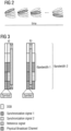
- a DSB may include a block capturing four signals: 2 synchronization signals, reference signal (beam reference signal/csi reference signal), and physical broadcast channel. It may also include signals and channels for paging support and distributing system information on frequency resources not reserved by synchronization signals and physical broadcast channel. As for physical broadcast channel, beam reference signal would be used as demodulation reference signal for other channels in the block as well. These frequency resources not reserved by synchronization signals and physical broadcast channel are depicted in Fig. 3 with the empty (white) blocks.
- the DSB in general can be seen to comprise also the shaded/marked blocks of Fig. 3 .
- the size and content of the DSB block may vary per eNB implementation and per detected transmission needs in the cell.
- DSB is considered to have a fixed amount of time and frequency domain resources independent of the transceiver architecture and configuration of DSBs (in predetermined location within the carrier).
- three time domain symbols may be allocated for DSB and a bandwidth of Bandwidth 2.
- Bandwidth 2 may be, for example, a system bandwidth.
- Bandwidth 1 is a reduced bandwidth for certain signals and channels in DSB.
- DSB may comprise, for example, synchronization signal(s) for time and frequency synchronization, physical broadcast channel to convey system information, paging indicator and reference signal(s).
- PBCH frequency domain multiplexing
- CSI acquisition CSI acquisition
- PBCH may be transmitted using transmit diversity method across parallel antenna / beam ports in order to use one set of resources per DSB.
- the UE may operate only using reduced bandwidth option, Bandwidth 1.
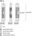
- Fig. 4 illustrates further implementation options for DSB to enable narrowband structure, according to an aspect.
- the example of Fig. 4 may be used in case part of the transceiver resources (e.g., some antenna ports) are performing periodical DSB transmission while others (e.g., some of the other antenna ports) are transmitting dedicated UE signalling on the DSB subframes.
- the transceiver resources e.g., some antenna ports
- others e.g., some of the other antenna ports
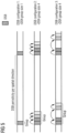
- Fig. 5 illustrates configuration options for DSB groups, according to one aspect.
- one group may have one or multiple DSBs.
- Each DSB indicates its position within the group and provides the group's parameters.
- DSBs within the group may be placed consecutively in time domain or may be discontinuously allocated in time.
- An opportunity for RF beam switching is provided between DSBs within a group.
- One OFDMA symbol may be reserved for such a guard time between DSB transmissions within a subframe.
- Other possibilities are to define certain number of samples for the explicit guard period or reuse first samples of the CP of the first symbol of the block for the guard period.
- Guard period used for link direction switching may also serve as a guard time between DSB transmissions (both within a subframe and between subframes).
- DSBs within a DSB group in subframes may be configured by the BS.
- the configuration may depend on the architecture used at the BS, as well as depending on the operation mode, but the UE does not need any assumption prior cell search.
- the configuration of the location of DSBs can be performed in a UE agnostic manner.
- the location of a DSB group may depend on the size of the group. For example, if the size of the group is one, the DSB may be located in DL control symbols or shared among DL control and data symbols. This is one possible configuration with digital architecture operating using sector beams because it minimizes consuming resource elements from data symbols while downlink control flexibility can be maintained because of having frequency selective digital beamforming capability at the BS.
- the DSBs may be located in the space reserved for DL data symbols (within a subframe). For instance, DSB allocation may start from the end of the subframe (or from the end of DL data part of the subframe).
- DMRS demodulation reference signal
- DMRS may, in an aspect, be located at the beginning of data part of the subframe (to facilitate fast detection at the receiver).
- filling from the end of the subframe may provide data transmission capability for data symbols preceding DSB blocks. Assuming demodulation RS would precede data symbols, unused data symbols due to DSB blocks would be more far away from DMRS than used ones.
- possibilities for having DMRS available in the "shorted subframe" can be maximized with this approach.
- the following rules may be defined for allocating DSB(s) of the DSB group into subframes.
- Each DSB may indicate the position of the DSB within the group and the total number of DSBs within the group.
- the maximum number of time domain DSB resources may be defined for subframe (e.g., 6). The maximum number may be needed in order for the UE to derive resource elements which are used by the DSB group in case DSBs within a group are spread across multiple subframes.
- the number can be fixed and defined in the specification for the subframe per subframe type (maximum number may depend on subframe type as well).
- the number can be defined by the BS/network system.
- each DSB would include information to the UE. This information (related to target cell) may also be included in a handover command to the UE.
- Another approach could be to use, for example, another RAT in case of multi-radio connectivity applied (UE could be connected to LTE when searching 5G cells and LTE provides information).
- DSBs may be spread across consecutive subframes having downlink data symbols (e.g., consecutive DL only subframes). If the DSB group has only one DSB, it may be allocated into the downlink control symbols, partly over downlink control and partly over downlink data symbols, or anywhere in the subframe.
- the DSB includes information for the UE to derive its location (i.e., mapping information) in relation to current subframe structure. This may be needed as there may be a need to define DSB resources and subframe structure (including DL control resource dimensioning in the subframe) independently from each other.
- the mapping information is implicit (such as DSB is always mapped to the last symbol(s) of the subframe), whereas in other cases the DSB includes an explicit indication of the mapping information.
- DSB may indicate (OFDM) symbol timing within the subframe.
- DSB may include indication about those symbol number(s) on the subframe on which the detected DSB block is allocated upon.
- the UE may detect the subframe structure from the received DSB.
- DSB indicates for instance maximum number (max_num) of DBSs within subframe which may indicate indirectly how many symbols are actually allocated for downlink control in the subframe. For example, if max_num of DSBs within subframe is three, that could mean two control symbols, but if the max_num of DSBs within subframe is four that could mean only one downlink control symbol only. Further, certain value may indicate that there is no uplink control symbol in the subframe where at least one DSB is allocated.
- DSBs of the group may be allocated into clusters within the period. For example, if the maximum number for allowed consecutive blocks is 6 and there are 9 blocks in the group, 6 blocks are allocated consecutively in time and rest 3 blocks are allocated consecutively in time with some offset from the cluster of blocks defined by said first 6 blocks. For instance, the cluster of blocks defined by said second 3 blocks are allocated on the subframe(s) with time offset half of the period of the group to the said first cluster. Another example is to increase the periodicity of the DSBs by the number of created clusters of blocks.
- the BS has configured 24 blocks and the maximum number for allowed blocks is 8, three clusters of DSBs are created within the group. The clusters are separated by 2 ms from each other or alternatively, basic periodicity for each DSB is increased by factor of three to 18 ms and clusters are separated by 6 ms.
- maximum allowed consecutive blocks is configured to infinite and using above assumptions, all 24 blocks are allocated consecutively in time domain (potentially omitting downlink and/or uplink control symbols) and spread across multiple consecutive subframes.
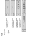
- Fig. 6 illustrates example mappings of DSBs into subframe structures, according to an aspect.
- DSBs are depicted as narrowband blocks relative to the total system bandwidth.
- DSB block may have some signals that are allocated total system bandwidth.
- beam RS bandwidth could be configurable and could be signaled via DSB. By default UE could always assume certain minimum bandwidth for beam RS in order to enable demodulation of PBCH using beam RS, initial measurements and beam selection when performing initial search and access to the cell.
- DSB may then indicate whether or not the beam RS is allocated over the full bandwidth or over narrow bandwidth.
- subframes allocated for DSB transmissions may be used in different manner by different transceiver units (antenna ports/ beam ports). For example, certain transceiver resources may transmit DSBs and certain transceiver resources may be used (simultaneously) for dedicated UE signaling (control and data) in those subframes. In this case, it may be desirable to define DSB to be narrow bandwidth block used by dedicated transceiver units while the rest of the system bandwidth could be used for dedicated signaling by other transceiver units (in other words to apply FDM between user data and DSB).
- one or two transceiver units may be allocated for sweeping DSBs while other transceiver units may be allocated for serving only dedicated UE signaling (control and data). In subframes DSBs are not transmitted, all transceiver units may be allocated for dedicated UE signaling.
- the BS may change number of transceiver units allocated for DSB transmission over time. For example, when the cell is empty, the BS may minimize the sweeping time by multiplexing all beam ports into one DSB transmission; while, when the cell is serving a high number of UEs, DSB transmissions may be performed by, for example, one or two antenna/beam ports.
- a single beam provides enough EIRP for common control signaling from link budget/coverage point of view and thus multiple beams can be transmitted in parallel to different spatial directions.
- narrowband DSB a possibility is to allocate some antenna ports to transmit DSBs in parallel and other antenna ports to transmit user plane data at the same time on the frequency resources not reserved by DSBs.
- Narrowband DSB would allow such configurability, for example when cell is empty the BS uses all the antenna ports in parallel for sweep, when there is load in the cell (high load), some APs perform sweeping while other perform user plane data transmission, thus preventing creation of data transmission gaps in downlink user plane transmissions due to sweeping.
- the UE can derive the configuration of the transceiver units for DSB transmission to be able to track BS beams.
- Fig. 7a illustrates options for resource element use for the antenna / beam ports transmitting DSBs, according to an aspect.
- Fig. 7b depicts options for resource element use for the antenna / beam ports not transmitting DSBs on the subframes where DSB resources are defined, according to an aspect. If PDSCH data allocation covers DSB region, the corresponding (dedicated) data/RS can be either rate matched or punctured around resource elements covering DSB region.
- one alternative may be to allocate DSB resource elements onto the edge of the system bandwidth to enable continuous allocation in frequency domain possibility for the antenna ports not transmitting DSBs on the subframes having DSB allocations. That would be beneficial, for instance, with single carrier transmission modulation schemes because DSBs are not in the middle of the system bandwidth to break frequency domain into two clusters.
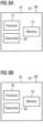
- Fig. 8a illustrates an example of an apparatus 10 according to an aspect.
- apparatus 10 may be a node, host, or server in a communications network or serving such a network.
- apparatus 10 may be a network node or access node for a radio access network, such as a base station e.g., NodeB (NB) in UMTS or eNodeB (eNB) in LTE or LTE-A.
- NB NodeB
- eNB eNodeB
- apparatus 10 may be other components within a radio access network. It should be noted that one of ordinary skill in the art would understand that apparatus 10 may include components or features not shown in Fig. 8a .
- apparatus 10 includes a processor 22 for processing information and executing instructions or operations.
- processor 22 may be any type of general or specific purpose processor. While a single processor 22 is shown in Fig. 8a , multiple processors may be utilized according to other aspects. In fact, processor 22 may include one or more of general-purpose computers, special purpose computers, microprocessors, digital signal processors (DSPs), field-programmable gate arrays (FPGAs), application-specific integrated circuits (ASICs), and processors based on a multi-core processor architecture, as examples.
- DSPs digital signal processors
- FPGAs field-programmable gate arrays
- ASICs application-specific integrated circuits
- Apparatus 10 may further include or be coupled to a memory 14 (internal or external), which may be coupled to processor 22, for storing information and instructions that may be executed by processor 22.
- Memory 14 may be one or more memories and of any type suitable to the local application environment, and may be implemented using any suitable volatile or nonvolatile data storage technology such as a semiconductor-based memory device, a magnetic memory device and system, an optical memory device and system, fixed memory, and removable memory.
- memory 14 can be comprised of any combination of random access memory (RAM), read only memory (ROM), static storage such as a magnetic or optical disk, or any other type of non-transitory machine or computer readable media.
- the instructions stored in memory 14 may include program instructions or computer program code that, when executed by processor 22, enable the apparatus 10 to perform tasks as described herein.
- apparatus 10 may also include or be coupled to one or more antennas 25 for transmitting and receiving signals and/or data to and from apparatus 10.
- Apparatus 10 may further include or be coupled to a transceiver 28 configured to transmit and receive information.
- transceiver 28 may be configured to modulate information on to a carrier waveform for transmission by the antenna(s) 25 and demodulate information received via the antenna(s) 25 for further processing by other elements of apparatus 10.
- transceiver 28 may be capable of transmitting and receiving signals or data directly.
- Processor 22 may perform functions associated with the operation of apparatus 10 which may include, for example, precoding of antenna gain/phase parameters, encoding and decoding of individual bits forming a communication message, formatting of information, and overall control of the apparatus 10, including processes related to management of communication resources.
- memory 14 may store software modules that provide functionality when executed by processor 22.
- the modules may include, for example, an operating system that provides operating system functionality for apparatus 10.
- the memory may also store one or more functional modules, such as an application or program, to provide additional functionality for apparatus 10.
- the components of apparatus 10 may be implemented in hardware, or as any suitable combination of hardware and software.
- apparatus 10 may be a network node or access node, such as a base station in UMTS or an eNB in LTE or LTE-A, for example.
- apparatus 10 may be controlled by at least one memory 14 and at least one processor 22 to configure a group of discovery signaling blocks (DSBs).
- Apparatus 10 may configure a DSB according to certain characteristics. For example, the DSB may have a predefined amount of time and frequency resources common to all subframe types and deployed architectures.
- the DSB may comprise multiple signals, for instance: synchronization signals for timing and partial or full physical layer cell ID acquisition, data channel (e.g. physical broadcast channel), and/or antenna port/beam port specific reference signals for physical broadcast channel (PBCH) demodulation, paging detection, beam detection, and channel state information (CSI) acquisition.
- PBCH physical broadcast channel
- CSI channel state information
- DSBs may be grouped together as illustrated in Fig. 5 discussed above, and each DSB may indicate its relationship within the group.
- the group may include one or multiple DSBs.
- apparatus 10 may configure the location of DSBs within a DSB group in subframes (e.g., DL only or S-DL subframes).
- DSBs of the group may be located consecutively in time or in a clustered manner in time.
- One DSB may include transmission of a plurality of signals from one or multiple radio frequency beams, and the one or more radio frequency beams used for the transmission of the signals in a given DSB are the same.
- apparatus 10 may be further controlled by at least one memory 14 and at least one processor 22 to map the DSBs of the group onto a subframe structure, and to include the group information into the DSBs.
- mapping information may also be included into the DSBs.
- each DSB may indicate the position of the DSB within the group (i.e., mapping information) and the total number of DSBs within the group (i.e., group information).
- the maximum number of time domain DSB resources may be defined for a subframe.
- the maximum number may be fixed and defined in the specification for the subframe.
- the maximum number may be defined by apparatus 10.
- apparatus 10 may be further controlled by at least one memory 14 and at least one processor 22 to transmit the DSBs in the subframe structure.
- apparatus 10 may be controlled by at least one memory 14 and at least one processor 22 to map the DSBs onto the subframe structure based on a size of the group and/or based on the subframe structure type configured in the cell.
- the DSBs are not allocated upon downlink and/or uplink control channel symbols if a number of subframes upon which blocks are mapped in a consecutive manner is below a given value.
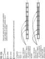
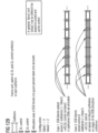
- Figs. 12a , 12b , and 12c illustrate examples of DSBs allocation.
- the first value could be 4 and the second value is 2, as non-limiting examples and other values are possible. These values may be pre-stored in the transmitting and receiving entities.
- first value e.g. six
- downlink control symbols are remained on the two (according to second value) edge subframes of the subframes DSBs are allocated upon and control symbols are omitted from other subframes.
- subframes control symbols may be remained in case the number of consecutive subframes DSBs are allocated is greater than given value (first value).
- the values may refer to a number of subframes.
- Downlink and uplink control symbols may be needed, for instance, for transmitting and receiving HARQ ack/nack feedback on previous subframes (data subframes) and sending scheduling grants for coming subframes.
- apparatus 10 may be controlled by at least one memory 14 and at least one processor 22 to map the DSBs in a subframe starting from the end of the data symbols, when the group size is greater than one. For example, the blocks of the group may be mapped upon last downlink symbols of the subframe.
- apparatus 10 may be controlled by at least one memory 14 and at least one processor 22 to map the DSBs in a subframe starting from a downlink control symbol and/or downlink data symbol when the group size is one. Applying only one DSB block may mean that the BS can cover the whole sector at once.
- in hybrid/analog beamforming even if there is only one DSB block in the group, that one DSB may be situated at the end of the subframe (one or more of the last symbols of the subframe).
- the number of radio frequency beams per block may be configured by apparatus 10.
- at least one radio frequency beam is transmitting block and at least one other radio frequency block is transmitting data symbols simultaneously.
- Radio resources for DSBs and data symbols may be separated in frequency domain.
- Fig. 8b illustrates an example of an apparatus 20 according to another aspect.
- apparatus 20 may be a node or element in a communications network or associated with such a network, such as a UE, mobile device, mobile unit, machine type UE or other device.
- apparatus 20 may be UE in LTE or LTE-A. It should be noted that one of ordinary skill in the art would understand that apparatus 20 may include components or features not shown in Fig. 8b .
- apparatus 20 includes a processor 32 for processing information and executing instructions or operations.
- processor 32 may be any type of general or specific purpose processor. While a single processor 32 is shown in Fig. 8b , multiple processors may be utilized according to other aspects. In fact, processor 32 may include one or more of general-purpose computers, special purpose computers, microprocessors, digital signal processors (DSPs), field-programmable gate arrays (FPGAs), application-specific integrated circuits (ASICs), and processors based on a multi-core processor architecture, as examples.
- DSPs digital signal processors
- FPGAs field-programmable gate arrays
- ASICs application-specific integrated circuits
- Apparatus 20 may further include or be coupled to a memory 34 (internal or external), which may be coupled to processor 32, for storing information and instructions that may be executed by processor 32.
- Memory 34 may be one or more memories and of any type suitable to the local application environment, and may be implemented using any suitable volatile or nonvolatile data storage technology such as a semiconductor-based memory device, a magnetic memory device and system, an optical memory device and system, fixed memory, and removable memory.
- memory 34 can be comprised of any combination of random access memory (RAM), read only memory (ROM), static storage such as a magnetic or optical disk, or any other type of non-transitory machine or computer readable media.
- the instructions stored in memory 34 may include program instructions or computer program code that, when executed by processor 32, enable the apparatus 20 to perform tasks as described herein.
- apparatus 20 may also include or be coupled to one or more antennas 35 for transmitting and receiving signals and/or data to and from apparatus 20.
- Apparatus 20 may further include a transceiver 38 configured to transmit and receive information.
- transceiver 38 may be configured to modulate information on to a carrier waveform for transmission by the antenna(s) 35 and demodulate information received via the antenna(s) 35 for further processing by other elements of apparatus 20.
- transceiver 38 may be capable of transmitting and receiving signals or data directly.
- Processor 32 may perform functions associated with the operation of apparatus 20 including, without limitation, precoding of antenna gain/phase parameters, encoding and decoding of individual bits forming a communication message, formatting of information, and overall control of the apparatus 20, including processes related to management of communication resources.
- memory 34 stores software modules that provide functionality when executed by processor 32.
- the modules may include, for example, an operating system that provides operating system functionality for apparatus 20.
- the memory may also store one or more functional modules, such as an application or program, to provide additional functionality for apparatus 20.
- the components of apparatus 20 may be implemented in hardware, or as any suitable combination of hardware and software.
- apparatus 20 may be a mobile device, such as a UE in LTE or LTE-A.
- apparatus 20 may be controlled by at least one memory 34 and at least one processor 32 to detect one or more DSBs, determine a beam configuration applied for the detected one or more DSBs, determine the group structure of the detected one or more DSBs, and determine a mapping of the detected one or more DSBs on one or more subframes.
- Apparatus 20 may also be controlled by at least one memory 3 and at least one processor 32 to determine a structure of the one or more subframes based on the determined group structure and the determined mapping, and to perform initial access to a cell of the network based on the result of the determining steps.
- Fig. 9a illustrates an example flow diagram of a method, according to one aspect of the disclosure.
- the method of Fig. 9a may be performed by a network node, such as a base station or eNB.
- the method includes, at 900, configuring a group of discovery signaling blocks (DSBs).
- the group of DSBs may be configured according to certain characteristics. For example, the DSB may have a predefined amount of time and frequency resources common to all subframe types and deployed architectures.
- the DSB comprises multiple signals, such as synchronization signals for timing and partial or full physical layer cell ID acquisition, data channel (e.g. physical broadcast channel), and/or antenna port/beam port specific reference signals for physical broadcast channel (PBCH) demodulation, paging detection, beam detection, and channel state information (CSI) acquisition.
- data channel e.g. physical broadcast channel
- PBCH physical broadcast channel
- CSI channel state information
- DSBs may be grouped together as illustrated in Fig. 5 discussed above, and each DSB may indicate its relationship within the group.
- the group may include one or multiple DSBs.
- the configuring may include configuring the location of DSBs within a DSB group in subframes (e.g., DL only or S-DL subframes).
- DSBs of the group may be located consecutively in time or in a clustered manner in time.
- One block may include transmission from one or multiple radio frequency beams.
- the method further includes, at 910, mapping the DSBs of the group onto a subframe structure, and, at 920, including the group information into each of the DSB(s).
- the including may further comprise including the mapping information in the DSBs.
- each DSB when mapping DSB(s) of the DSB group into subframes, each DSB may indicate the position of the DSB within the group and the total number of DSBs within the group.
- the maximum number of time domain DSB resources may be defined for a subframe. In one aspect, the maximum number may be fixed and defined in the specification for the subframe. In another aspect, the maximum number may be defined by the base station or eNB.
- the method further includes, at 925, transmitting the DSB(s) in the subframe structure.
- the mapping may include mapping the DSBs onto the subframe structure based on a size of the group and/or based on the subframe structure type configured in the cell.
- the DSBs are not allocated upon downlink and/or uplink control channel symbols if a number of subframes upon which blocks are mapped in a consecutive manner is below a given value.
- the mapping may include mapping the DSBs in a subframe starting from the end of the data symbols, when the group size is greater than one.
- the mapping may include mapping the DSBs in a subframe starting from a downlink control symbol and/or downlink data symbol when the group size is one.
- the number of radio frequency beams per block may be configured by the base station or eNB.
- at least one radio frequency beam is transmitting block and at least one other radio frequency block is transmitting data symbols simultaneously.
- Radio resources for DSBs and data symbols may be separated in frequency domain.
- Fig. 9b illustrates an example flow diagram of a method, according to another aspect of the disclosure.
- the method of Fig. 9b may be performed by a device, such as a UE in LTE or LTE-A.
- the method includes, at 950, detecting one or more DSBs.
- the method includes, determining a beam configuration applied for the detected one or more DSBs.
- the method further includes, at 970, determining the group structure of the detected one or more DSBs, and, at 980, determining a mapping of the detected one or more DSBs on one or more subframes.
- the method also includes, at 985, determining a structure of the one or more subframes based on the determined group structure and the determined mapping.
- the method then includes, at 990, performing initial access to a cell of the network based on the result of the determining steps.
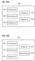
- Fig. 10a illustrates a block diagram of an apparatus 800, according to one aspect.
- apparatus 800 may include a processing unit or means 801 for controlling apparatus 800 and for carrying out instructions of a computer program, for example, by performing arithmetic, logical, control and input/output (I/O) operations specified by the instructions.
- Apparatus 800 may also include a storage unit or means 803 for storing information including, but not limited to, computer program instructions or software modules that provide functionality when executed by processing unit 801.
- Apparatus 800 may further include a transceiving unit or means 802 for receiving or transmitting information.
- Apparatus 800 may also include a configuring unit or means 804 and a mapping unit or means 805.
- the configuring unit 804 may configure a group of discovery signaling blocks (DSBs).
- the group of DSBs may be configured according to certain characteristics.
- the DSB may have a predefined amount of time and frequency resources common to all subframe types and deployed architectures.
- the group may include one or multiple DSBs.
- the configuring unit 804 may configure the location of DSBs within a DSB group in subframes (e.g., DL only or S-DL subframes).
- DSBs of the group may be located consecutively in time or in a clustered manner in time.
- One block may include transmission from one or multiple radio frequency beams.
- mapping unit 805 may map the DSBs of the group onto a subframe structure.
- the configuring unit 804 may cause the including of the group information and optionally the mapping information into the DSBs.
- each DSB may indicate the position of the DSB within the group and the total number of DSBs within the group.
- the maximum number of time domain DSB resources may be defined for a subframe. In one aspect, the maximum number may be fixed and defined in the specification for the subframe. In another aspect, the maximum number may be defined by apparatus 800.
- Transceiving unit or means 802 may cause the transmitting of the DSBs in the subframe structure.
- the mapping unit 805 may map the DSBs onto the subframe structure based on a size of the group and/or based on the subframe structure type configured in the cell.
- the DSBs are not allocated upon downlink and/or uplink control channel symbols if a number of subframes upon which blocks are mapped in a consecutive manner is below a given value.
- the mapping unit 805 may map the DSBs in a subframe starting from the end of the data symbols, when the group size is greater than one.
- the mapping unit 805 may map the DSBs in a subframe starting from a downlink control symbol and/or downlink data symbol when the group size is one.
- the number of radio frequency beams per block may be configured by the base station or eNB.
- at least one radio frequency beam is transmitting block and at least one other radio frequency block is transmitting data symbols simultaneously.
- Radio resources for DSBs and data symbols may be separated in frequency domain.
- Fig. 10b illustrates a block diagram of an apparatus 850, according to one aspect.
- apparatus 850 may include a processing unit or means 851 for controlling apparatus 850 and for carrying out instructions of a computer program, for example, by performing arithmetic, logical, control and input/output (I/O) operations specified by the instructions.
- Apparatus 850 may also include a storage unit or means 853 for storing information including, but not limited to, computer program instructions or software modules that provide functionality when executed by processing unit 851.
- Apparatus 850 may further include a transceiving unit or means 852 for receiving or transmitting information.
- Apparatus 850 may also include a detecting unit 854 and a determining unit 855.
- detecting unit 854 may detect one or more DSBs.
- Determining unit 855 may determine a beam configuration applied for the detected one or more blocks, determine the group structure of the detected one or more DSBs, determine a mapping of the detected one or more DSBs on one or more subframes, and determine a structure of the one or more subframes based on the determined group structure and the determined mapping.
- the transceiving unit or means 852 may cause the performing of initial access to a cell of the network based on the result of the determining steps.
- aspects of the disclosure provide several advantages and technical improvements. For example, aspects support all possible BS architectures (fully digital, hybrid, fully analog). In addition, aspects are UE agnostic. In other words, the UE does not need to know the BS architecture in advance. Further, aspects may support both beamformed and conventional (sector beam approach) approaches for the common control plane (PBCH, PRACH). Certain aspects have built-in support for efficient usage of BS TXRU (and other hardware resources). Also, aspects allow for minimizing the duration of one sweep of beamformed control channel transmission. Hence, it has a positive impact on the UEs power consumption (i.e., UE power consumption is reduced). Additionally, aspects allow simultaneous transmission of data and DSB. This will minimize the system overhead of DSB transmission.
- PBCH common control plane
- programs also called program products or computer programs, including software routines, applets and macros
- a computer program product may comprise one or more computer-executable components which, when the program is run, are configured to carry out aspects.
- the one or more computer-executable components may be at least one software code or portions of it. Modifications and configurations required for implementing functionality of an aspect may be performed as routine(s), which may be implemented as added or updated software routine(s).
- Software routine(s) may be downloaded into the apparatus.
- Software or a computer program code or portions of it may be in a source code form, object code form, or in some intermediate form, and it may be stored in some sort of carrier, distribution medium, or computer readable medium, which may be any entity or device capable of carrying the program.
- carrier include a record medium, computer memory, read-only memory, photoelectrical and/or electrical carrier signal, telecommunications signal, and software distribution package, for example.
- the computer program may be executed in a single electronic digital computer or it may be distributed amongst a number of computers.
- the computer readable medium or computer readable storage medium may be a non-transitory medium.
- any method or apparatus described herein may be performed by hardware, for example through the use of an application specific integrated circuit (ASIC), a programmable gate array (PGA), a field programmable gate array (FPGA), or any other combination of hardware and software.
- ASIC application specific integrated circuit
- PGA programmable gate array
- FPGA field programmable gate array
- the functionality may be implemented as a signal, a non-tangible means that may be carried by an electromagnetic signal downloaded from the Internet or other network.
- an apparatus such as a node, device, or a corresponding component, may be configured as a computer or a microprocessor, such as single-chip computer element, or as a chipset, including at least a memory for providing storage capacity used for arithmetic operation and an operation processor for executing the arithmetic operation.
- a microprocessor such as single-chip computer element, or as a chipset, including at least a memory for providing storage capacity used for arithmetic operation and an operation processor for executing the arithmetic operation.
Landscapes
- Engineering & Computer Science (AREA)
- Signal Processing (AREA)
- Computer Networks & Wireless Communication (AREA)
- Computer Security & Cryptography (AREA)
- Mobile Radio Communication Systems (AREA)
Claims (14)
- Verfahren (9A), das Folgendes umfasst:Auslegen (900) einer Gruppe von Entdeckungssignalisierungsblöcken durch einen Netzwerkknoten, wo ein Entdeckungssignalisierungsblock mindestens ein Synchronisationssignal und einen physischen Broadcastkanal umfasst;Zuordnen (910) der Entdeckungssignalisierungsblöcke der Gruppe durch den Netzwerkknoten zu einer Unterframestruktur;Einbinden (920) von Zuordnungsinformationen und Gruppeninformationen durch den Netzwerkknoten in jeden der Entdeckungssignalisierungsblöcke für eine Teilnehmereinrichtung, um eine Gruppenstruktur und die Zuordnung der Entdeckungssignalisierungsblöcke der Gruppe zur Unterframestruktur abzuleiten, wobei die Zuordnungsinformationen anzeigen, wo sich ein Entdeckungssignalisierungsblock in der Unterframestruktur befindet, und die Gruppeninformationen Informationen darüber umfassen, wie viele Entdeckungssignalisierungsblöcke sich in der Gruppe befinden; undÜbertragen (925) der Entdeckungssignalisierungsblöcke in der Unterframestruktur durch den Netzwerkknoten.
- Verfahren (9A) nach Anspruch 1, wobei jeder der Entdeckungssignalisierungsblöcke selbstdetektierbar und selbstdecodierbar ist.
- Verfahren (9A) nach Anspruch 1 oder 2, wobei die Gruppe einen oder mehrere Entdeckungssignalisierungsblöcke umfasst.
- Verfahren (9A) nach einem der Ansprüche 1 bis 3, wobei ein Entdeckungssignalisierungsblock eine Übertragung einer Vielzahl von Signalen von einem oder mehreren Funkfrequenzstrahlen umfasst, und der eine oder die mehreren Funkfrequenzstrahlen, die zur Übertragung der Signale in einem gegebenen Entdeckungssignalisierungsblock verwendet werden, dieselben sind.
- Verfahren (9A) nach einem der Ansprüche 1 bis 4, wobei die Zuordnung auf mindestens einem einer Größe der Gruppe oder einer Art der Unterframestruktur, die in einer Zelle ausgelegt ist, basiert.
- Netzwerkknoten (10), der Folgendes umfasst:mindestens einen Prozessor; undmindestens einen Speicher, der einen Computerprogrammcode umfasst,der mindestens eine Speicher und der Computerprogrammcode sind dazu ausgelegt, den Netzwerkknoten mit dem mindestens einen Prozessor mindestens zu Folgendem zu veranlassenAuslegen (900) einer Gruppe von Entdeckungssignalisierungsblöcken, wo ein Entdeckungssignalisierungsblock mindestens ein Synchronisationssignal und einen physischen Broadcastkanal umfasst;Zuordnen (910) der Entdeckungssignalisierungsblöcke der Gruppe zu einer Unterframestruktur;Einbinden (920) von Zuordnungsinformationen und Gruppeninformationen in jeden der Entdeckungssignalisierungsblöcke für eine Teilnehmereinrichtung, um eine Gruppenstruktur und die Zuordnung der Entdeckungssignalisierungsblöcke der Gruppe zur Unterframestruktur abzuleiten, wobei die Zuordnungsinformationen anzeigen, wo sich ein Entdeckungssignalisierungsblock in der Unterframestruktur befindet, und die Gruppeninformationen Informationen darüber umfassen, wie viele Entdeckungssignalisierungsblöcke sich in der Gruppe befinden; undÜbertragen (925) der Entdeckungssignalisierungsblöcke in der Unterframestruktur.
- Netzwerkknoten (10) von Anspruch 6, wobei jeder der Entdeckungssignalisierungsblöcke selbstdetektierbar und selbstdecodierbar ist.
- Netzwerkknoten (10) nach Anspruch 6 oder 7, wobei die Gruppe einen oder mehrere Entdeckungssignalisierungsblöcke umfasst.
- Netzwerkknoten (10) nach einem der Ansprüche 6 bis 8, wobei ein Entdeckungssignalisierungsblock eine Übertragung einer Vielzahl von Signalen von einem oder mehreren Funkfrequenzstrahlen umfasst, und der eine oder die mehreren Funkfrequenzstrahlen, die zur Übertragung der Signale in einem gegebenen Entdeckungssignalisierungsblock verwendet werden, dieselben sind.
- Netzwerkknoten (10) nach einem der Ansprüche 6 bis 9, wobei die Zuordnung auf mindestens einem einer Größe der Gruppe oder einer Art der Unterframestruktur, die in einer Zelle ausgelegt ist, basiert.
- Verfahren (9B), das Folgendes umfasst:Detektieren (950) einer Gruppe von Entdeckungssignalisierungsblöcken durch eine Teilnehmereinrichtung in einer Unterframestruktur, wo ein Entdeckungssignalisierungsblock mindestens ein Synchronisationssignal und einen physischen Broadcastkanal umfasst und wo jeder Entdeckungssignalisierungsblock Zuordnungsinformationen und Gruppeninformationen für die Teilnehmereinrichtung beinhaltet, um eine Gruppenstruktur und eine Zuordnung der Entdeckungssignalisierungsblöcke der Gruppe zur Unterframestruktur abzuleiten, wobei die Zuordnungsinformationen anzeigen, wo sich ein Entdeckungssignalisierungsblock in der Unterframestruktur befindet, und die Gruppeninformationen Informationen darüber umfassen, wie viele Entdeckungssignalisierungsblöcke sich in der Gruppe befinden;Bestimmen (960) einer Strahlauslegung, die für die detektierten Blöcke angewandt wird, durch die Teilnehmereinrichtung;Bestimmen (970) einer Gruppenstruktur der detektierten Entdeckungssignalisierungsblöcke durch die Teilnehmereinrichtung auf Basis der Gruppeninformationen;Bestimmen (980) einer Zuordnung der detektierten Entdeckungssignalisierungsblöcke durch die Teilnehmereinrichtung zur Unterframestruktur auf Basis der Zuordnungsinformationen;Bestimmen (985) einer Struktur des Unterframes durch die Teilnehmereinrichtung auf Basis der bestimmten Gruppenstruktur und der bestimmten Zuordnung; undDurchführen (990) eines anfänglichen Zugangs zu einer Zelle durch die Teilnehmereinrichtung auf Basis der Bestimmungsschritte.
- Verfahren (9B) nach Anspruch 11, wobei jeder der Entdeckungssignalisierungsblöcke selbstdetektierbar oder selbstdecodierbar ist.
- Teilnehmereinrichtung (20), die Folgendes umfasst:mindestens einen Prozessor; undmindestens einen Speicher, der einen Computerprogrammcode umfasst,wobei der mindestens eine Speicher und der Computerprogrammcode dazu ausgelegt sind, die Teilnehmereinrichtung mit dem mindestens einen Prozessor mindestens zu Folgendem zu veranlassenDetektieren (950) einer Gruppe von Entdeckungssignalisierungsblöcken in einer Unterframestruktur, wo ein Entdeckungssignalisierungsblock mindestens ein Synchronisationssignal und einen physischen Broadcastkanal umfasst und wo jeder Entdeckungssignalisierungsblock Zuordnungsinformationen und Gruppeninformationen für die Teilnehmereinrichtung beinhaltet, um eine Gruppenstruktur und eine Zuordnung der Entdeckungssignalisierungsblöcke der Gruppe zur Unterframestruktur abzuleiten, wobei die Zuordnungsinformationen anzeigen, wo sich ein Entdeckungssignalisierungsblock in der Unterframestruktur befindet, und die Gruppeninformationen Informationen darüber umfassen, wie viele Entdeckungssignalisierungsblöcke sich in der Gruppe befinden;Bestimmen (960) einer Strahlauslegung, die für die detektierten Blöcke angewandt wird;Bestimmen (970) einer Gruppenstruktur der detektierten Entdeckungssignalisierungsblöcke auf Basis der Gruppeninformationen;Bestimmen (980) einer Zuordnung der detektierten Entdeckungssignalisierungsblöcke zur Unterframestruktur auf Basis der Zuordnungsinformationen;Bestimmen (985) einer Struktur des Unterframes auf Basis der bestimmten Gruppenstruktur und der bestimmten Zuordnung; undDurchführen (990) eines anfänglichen Zugangs zu einer Zelle auf Basis der Bestimmungsschritte.
- Computerprogramm, das auf einem nichttransitorischen computerlesbaren Medium enthalten ist, wobei das Computerprogramm dazu ausgelegt ist, einen Prozessor (22, 32) zu steuern, um ein Verfahren nach einem der Ansprüche 1 bis 5 oder 11 durchzuführen.
Applications Claiming Priority (2)
| Application Number | Priority Date | Filing Date | Title |
|---|---|---|---|
| US14/993,296 US10536940B2 (en) | 2016-01-12 | 2016-01-12 | Discovery signal block mapping |
| PCT/EP2016/079061 WO2017121534A1 (en) | 2016-01-12 | 2016-11-29 | Discovery signal block mapping |
Publications (3)
| Publication Number | Publication Date |
|---|---|
| EP3403444A1 EP3403444A1 (de) | 2018-11-21 |
| EP3403444C0 EP3403444C0 (de) | 2025-05-21 |
| EP3403444B1 true EP3403444B1 (de) | 2025-05-21 |
Family
ID=57442675
Family Applications (1)
| Application Number | Title | Priority Date | Filing Date |
|---|---|---|---|
| EP16804750.4A Active EP3403444B1 (de) | 2016-01-12 | 2016-11-29 | Entdeckungssignalblock-mapping |
Country Status (6)
| Country | Link |
|---|---|
| US (3) | US10536940B2 (de) |
| EP (1) | EP3403444B1 (de) |
| CN (2) | CN108713333B (de) |
| MY (1) | MY199523A (de) |
| PH (1) | PH12018501472A1 (de) |
| WO (1) | WO2017121534A1 (de) |
Families Citing this family (27)
| Publication number | Priority date | Publication date | Assignee | Title |
|---|---|---|---|---|
| US10200353B2 (en) | 2013-07-25 | 2019-02-05 | Convida Wireless, Llc | End-to-end M2M service layer sessions |
| CN105981316B (zh) * | 2014-02-13 | 2018-07-06 | Lg电子株式会社 | 在支持机器型通信的无线接入系统中发送探测参考信号的方法和设备 |
| CA3010228C (en) * | 2015-12-31 | 2023-10-31 | Huawei Technologies Co., Ltd. | Beamforming method, receiver, transmitter, and system |
| KR102153077B1 (ko) | 2016-04-20 | 2020-09-07 | 콘비다 와이어리스, 엘엘씨 | 다운링크 동기화 |
| JP6837492B2 (ja) | 2016-04-20 | 2021-03-03 | コンヴィーダ ワイヤレス, エルエルシー | 新しい無線における物理チャネル |
| WO2017184865A1 (en) | 2016-04-20 | 2017-10-26 | Convida Wireless, Llc | Configurable reference signals |
| EP3446515B1 (de) | 2016-04-20 | 2020-12-02 | Convida Wireless, LLC | Bereitstellen von systeminformationen |
| CN110233694B (zh) * | 2016-04-25 | 2020-11-24 | 韩国电子通信研究院 | 传送/接收发现信号的方法 |
| EP3455985B1 (de) | 2016-05-11 | 2022-03-09 | Convida Wireless, LLC | Neuer funk-downlink-steuerkanal |
| US11218236B2 (en) | 2016-06-01 | 2022-01-04 | Qualcomm Incorporated | Time division multiplexing of synchronization channels |
| US11563505B2 (en) * | 2016-06-01 | 2023-01-24 | Qualcomm Incorporated | Time division multiplexing of synchronization channels |
| WO2017218847A1 (en) | 2016-06-15 | 2017-12-21 | Convida Wireless, Llc | Grant-less operations |
| CN109565370B (zh) | 2016-06-15 | 2021-06-15 | 康维达无线有限责任公司 | 用于新无线电的上传控制信令的装置 |
| WO2017218849A1 (en) | 2016-06-15 | 2017-12-21 | Convida Wireless, Llc | Network slice discovery and selection |
| JP2019518392A (ja) | 2016-06-15 | 2019-06-27 | コンヴィーダ ワイヤレス, エルエルシー | 新しい無線のための許可不要アップリンク伝送 |
| CN112202541B (zh) | 2016-08-04 | 2022-02-22 | 中兴通讯股份有限公司 | 一种信号传输方法及装置 |
| US10840982B2 (en) | 2016-08-11 | 2020-11-17 | Convidia Wireless, LLC | Beamforming sweeping and training in a flexible frame structure for new radio |
| CN109644062B (zh) * | 2016-09-29 | 2021-11-16 | 富士通株式会社 | 参考信号的传输装置、方法以及通信系统 |
| CN109891772B (zh) | 2016-11-03 | 2022-10-04 | 康维达无线有限责任公司 | Nr中的帧结构 |
| US10938545B2 (en) * | 2016-11-14 | 2021-03-02 | Qualcomm Incorporated | Synchronization signal transmission techniques for peak-to-average power ratio reduction |
| US10044420B2 (en) * | 2016-12-15 | 2018-08-07 | Hong Kong Applied Science and Technology Research Institute Company Limited | Closed-loop massive MIMO system architecture |
| US10666406B2 (en) | 2017-06-16 | 2020-05-26 | Qualcomm Incorporated | Signaling information in physical broadcast channel (PBCH) demodulation reference signals (DMRS) |
| US10484968B2 (en) * | 2018-03-28 | 2019-11-19 | Qualcomm Incorporated | Beam direction assisted paging |
| CN112753265B (zh) | 2018-09-27 | 2025-02-11 | 交互数字专利控股公司 | 新无线电的未经许可的频谱中的子频带操作 |
| WO2020034432A1 (en) * | 2018-11-02 | 2020-02-20 | Zte Corporation | Time domain mapping of synchronization signal blocks |
| CN110380763B (zh) * | 2019-07-23 | 2021-05-11 | 东南大学 | 收发方向图非互易全数字波束成形天线阵列及其实现方法 |
| CN115379534A (zh) * | 2021-05-18 | 2022-11-22 | 华为技术有限公司 | 通信方法和通信装置 |
Family Cites Families (36)
| Publication number | Priority date | Publication date | Assignee | Title |
|---|---|---|---|---|
| US8948208B2 (en) * | 2008-11-07 | 2015-02-03 | Qualcomm Incorporated | Conveying information through phase offset on PSS relative to DL-RS |
| CN102461067B (zh) * | 2009-06-24 | 2015-02-25 | 瑞典爱立信有限公司 | 供通信网络的网络管理中使用的方法和系统 |
| US8902858B2 (en) * | 2009-07-15 | 2014-12-02 | Qualcomm Incorporated | Low reuse preamble |
| KR101639407B1 (ko) * | 2009-07-30 | 2016-07-13 | 엘지전자 주식회사 | 이동통신 시스템에서 채널상태정보를 전송하는 장치 및 그 방법 |
| EP2282574B1 (de) * | 2009-08-07 | 2017-08-09 | Intel Deutschland GmbH | Anordnung und Verfahren zur Beurteilung des Netzwerkverkehrs basierend auf dem Winkel der Ankunftsbestimmung in einen zellulären Netzwerk |
| US9402264B2 (en) * | 2011-09-30 | 2016-07-26 | Intel Corporation | Methods to transport internet traffic over multiple wireless networks simultaneously |
| JP6045812B2 (ja) | 2012-04-27 | 2016-12-14 | 株式会社Nttドコモ | 無線通信方法、無線基地局及び無線通信システム |
| WO2014042373A1 (ko) * | 2012-09-16 | 2014-03-20 | 엘지전자 주식회사 | 무선 통신 시스템에서 브로드캐스트 신호를 수신 또는 전송하기 위한 방법 및 이를 위한 장치 |
| US9072000B2 (en) * | 2012-10-19 | 2015-06-30 | Qualcomm Incorporated | Power efficient relay discovery protocol |
| KR101988506B1 (ko) * | 2012-12-14 | 2019-09-30 | 삼성전자 주식회사 | 무선 이동통신 시스템에서 디스커버리 신호를 송/수신하는 방법 및 장치 |
| EP3709730A1 (de) * | 2013-01-16 | 2020-09-16 | Interdigital Patent Holdings, Inc. | Erkennungssignalerzeugung und -empfang |
| US9692584B2 (en) * | 2013-01-17 | 2017-06-27 | Telefonatiebolaget L M Ericsson (Publ) | Methods of radio communications using different subframe configurations and related radio and/or network nodes |
| US9955408B2 (en) * | 2013-02-22 | 2018-04-24 | Samsung Electronics Co., Ltd. | Network-assisted multi-cell device discovery protocol for device-to-device communications |
| US9451629B2 (en) * | 2013-02-26 | 2016-09-20 | Qualcomm Incorporated | Resource allocation for the coexistence of peer discovery and legacy LTE traffic |
| CN109510697B (zh) * | 2013-07-04 | 2021-07-06 | 韩国电子通信研究院 | 处理无线电链路故障的方法 |
| US10038529B2 (en) * | 2013-08-07 | 2018-07-31 | Sun Patent Trust | Base station apparatus, terminal apparatus, transmitting method, and receiving method |
| US9967809B2 (en) * | 2013-09-24 | 2018-05-08 | Zte Wistron Telecom Ab | Method and apparatus for modified reference signal transmission for cell discovery |
| US20150133102A1 (en) * | 2013-11-10 | 2015-05-14 | Telefonaktiebolaget L M Ericsson (Publ) | Triggering of direct discovery signals |
| CN104703200B (zh) * | 2013-12-06 | 2018-04-17 | 电信科学技术研究院 | 一种d2d信号检测方法及设备 |
| CN104734762B (zh) * | 2013-12-20 | 2018-12-25 | 中兴通讯股份有限公司 | 一种发现信号的处理方法、装置和系统 |
| WO2015109153A1 (en) | 2014-01-17 | 2015-07-23 | Interdigital Patent Holdings, Inc. | 3gpp mmw access link system architecture |
| KR102313972B1 (ko) * | 2014-01-21 | 2021-10-18 | 엘지전자 주식회사 | 무선 통신 시스템에서 D2D(device-to-device) 자원에 관한 정보를 전송하는 방법 및 장치 |
| JP2015164281A (ja) | 2014-01-31 | 2015-09-10 | 株式会社Nttドコモ | ユーザ装置、基地局、及び通信方法 |
| EP3697158B1 (de) * | 2014-03-30 | 2021-12-08 | LG Electronics Inc. | Verfahren zum senden/empfangen von downlink-steuerinformationen in einem drahtloskommunikationssystem mit unterstützung von vorrichtung-zu-vorrichtung-kommunikation und einrichtung dafür |
| US10097321B2 (en) * | 2014-05-08 | 2018-10-09 | Qualcomm Incorporated | Cooperative techniques between lower-frequency carriers and millimeter-wave channels for discovery and synchronization and beamforming |
| JP6359757B2 (ja) * | 2014-08-07 | 2018-07-18 | エルジー エレクトロニクス インコーポレイティド | 無線通信システムにおけるデータを送受信するための方法及び装置 |
| US10080128B2 (en) * | 2014-08-08 | 2018-09-18 | Lg Electronics Inc. | Method and apparatus for configuring D2D discovery specific logical channel group in wireless communication system |
| WO2016065068A2 (en) * | 2014-10-21 | 2016-04-28 | Intel IP Corporation | Methods and apparatuses to form self-organized multi-hop millimeter wave backhaul links |
| US11356834B2 (en) * | 2015-01-21 | 2022-06-07 | Samsung Electronics Co., Ltd. | System and method of D2D discovery message transmission |
| EP3273717A4 (de) * | 2015-03-16 | 2018-11-14 | NTT DoCoMo, Inc. | Benutzervorrichtung, basisstation und kommunikationsverfahren |
| WO2016186268A1 (ko) * | 2015-05-15 | 2016-11-24 | 엘지전자(주) | 단말 간 통신을 지원하는 무선 통신 시스템에서 데이터 전달 방법 및 이를 위한 장치 |
| WO2017002282A1 (ja) * | 2015-06-29 | 2017-01-05 | 日本電気株式会社 | 無線通信のための方法及び装置 |
| JP6680299B2 (ja) * | 2015-06-29 | 2020-04-15 | 日本電気株式会社 | 無線通信のための方法及び装置 |
| CN107852624B (zh) * | 2015-07-29 | 2021-10-29 | 苹果公司 | 用于动态毫米波笔形小区通信的用户设备(ue)和方法 |
| IL242762A0 (en) * | 2015-11-24 | 2016-04-21 | Moti Maimon | A method and system for creating a communication channel between a smart object and a smart phone |
| CN106686571B (zh) * | 2015-11-11 | 2020-06-16 | 华为技术有限公司 | 一种处理发现消息的方法和装置 |
-
2016
- 2016-01-12 US US14/993,296 patent/US10536940B2/en active Active
- 2016-11-29 CN CN201680082306.3A patent/CN108713333B/zh active Active
- 2016-11-29 CN CN202211406339.2A patent/CN115720359B/zh active Active
- 2016-11-29 MY MYPI2018001279A patent/MY199523A/en unknown
- 2016-11-29 EP EP16804750.4A patent/EP3403444B1/de active Active
- 2016-11-29 WO PCT/EP2016/079061 patent/WO2017121534A1/en not_active Ceased
-
2018
- 2018-07-10 PH PH12018501472A patent/PH12018501472A1/en unknown
-
2019
- 2019-12-06 US US16/705,905 patent/US11064485B2/en active Active
-
2021
- 2021-06-09 US US17/343,222 patent/US11723001B2/en active Active
Also Published As
| Publication number | Publication date |
|---|---|
| US11064485B2 (en) | 2021-07-13 |
| US20210298018A1 (en) | 2021-09-23 |
| WO2017121534A1 (en) | 2017-07-20 |
| EP3403444A1 (de) | 2018-11-21 |
| CN108713333A (zh) | 2018-10-26 |
| US11723001B2 (en) | 2023-08-08 |
| EP3403444C0 (de) | 2025-05-21 |
| MY199523A (en) | 2023-11-03 |
| US10536940B2 (en) | 2020-01-14 |
| US20200112956A1 (en) | 2020-04-09 |
| PH12018501472A1 (en) | 2019-03-11 |
| CN115720359A (zh) | 2023-02-28 |
| CN108713333B (zh) | 2023-05-02 |
| US20170201980A1 (en) | 2017-07-13 |
| CN115720359B (zh) | 2026-04-07 |
Similar Documents
| Publication | Publication Date | Title |
|---|---|---|
| US11723001B2 (en) | Discovery signal block mapping | |
| EP3446410B1 (de) | Auf strahlreferenzsignal basierende schmalbandkanalmessung und cqi-berichterstattung | |
| US10727920B2 (en) | Dynamic CSI-RS transmission for enhanced FD-MIMO | |
| US11290987B2 (en) | Slot structure linkage in wireless systems | |
| EP3567899B1 (de) | Strahlenspezifischer und zellenspzifischer messbericht | |
| US9681429B2 (en) | Method and device for allocating search space of control channel in subframe | |
| CA3028945C (en) | BASE STATION APPARATUS, TERMINAL APPARATUS, AND COMMUNICATION METHOD | |
| US11563541B2 (en) | Resource mapping for broadcasted system information | |
| US11395369B2 (en) | Methods, apparatuses and systems for dynamic spectrum sharing between legacy and next generation networks | |
| US11202308B2 (en) | Resource allocation pattern signaling for mini-slots | |
| US20230276249A1 (en) | Apparatuses and methods for flexible spectrum | |
| EP3484065A2 (de) | Basisstationsvorrichtung, endgerätevorrichtung und kommunikationsverfahren | |
| US12556349B2 (en) | Apparatuses and methods for flexible spectrum | |
| US12470942B2 (en) | Techniques for dynamic spectrum sharing between radio access technologies | |
| US10462836B2 (en) | Method and apparatus for supporting amorphous cell in wireless communication system | |
| US12501405B2 (en) | Multiple component carrier simultaneous transmission control indicator state activation with multiple transmission and reception point transmission | |
| US11140683B2 (en) | Methods and apparatuses for periodic uplink signals with hybrid transceiver architectures | |
| US20190124650A1 (en) | Method and apparatus for sending and receiving control signaling in communications system | |
| US11997698B2 (en) | Broadcast control channel decoding in dedicated carrier | |
| KR20260014260A (ko) | 이기종 무선 접속 기술로 구성되는 무선 통신 시스템에서 신호를 송수신하는 방법 및 장치 | |
| CN121368919A (zh) | 无线通信系统中用于信道状态信息报告的组公共请求的方法和装置 |
Legal Events
| Date | Code | Title | Description |
|---|---|---|---|
| STAA | Information on the status of an ep patent application or granted ep patent |
Free format text: STATUS: UNKNOWN |
|
| STAA | Information on the status of an ep patent application or granted ep patent |
Free format text: STATUS: THE INTERNATIONAL PUBLICATION HAS BEEN MADE |
|
| PUAI | Public reference made under article 153(3) epc to a published international application that has entered the european phase |
Free format text: ORIGINAL CODE: 0009012 |
|
| STAA | Information on the status of an ep patent application or granted ep patent |
Free format text: STATUS: REQUEST FOR EXAMINATION WAS MADE |
|
| 17P | Request for examination filed |
Effective date: 20180813 |
|
| AK | Designated contracting states |
Kind code of ref document: A1 Designated state(s): AL AT BE BG CH CY CZ DE DK EE ES FI FR GB GR HR HU IE IS IT LI LT LU LV MC MK MT NL NO PL PT RO RS SE SI SK SM TR |
|
| AX | Request for extension of the european patent |
Extension state: BA ME |
|
| DAV | Request for validation of the european patent (deleted) | ||
| DAX | Request for extension of the european patent (deleted) | ||
| RAP1 | Party data changed (applicant data changed or rights of an application transferred) |
Owner name: NOKIA SOLUTIONS AND NETWORKS OY |
|
| STAA | Information on the status of an ep patent application or granted ep patent |
Free format text: STATUS: EXAMINATION IS IN PROGRESS |
|
| 17Q | First examination report despatched |
Effective date: 20210527 |
|
| GRAP | Despatch of communication of intention to grant a patent |
Free format text: ORIGINAL CODE: EPIDOSNIGR1 |
|
| STAA | Information on the status of an ep patent application or granted ep patent |
Free format text: STATUS: GRANT OF PATENT IS INTENDED |
|
| INTG | Intention to grant announced |
Effective date: 20241104 |
|
| GRAJ | Information related to disapproval of communication of intention to grant by the applicant or resumption of examination proceedings by the epo deleted |
Free format text: ORIGINAL CODE: EPIDOSDIGR1 |
|
| STAA | Information on the status of an ep patent application or granted ep patent |
Free format text: STATUS: EXAMINATION IS IN PROGRESS |
|
| GRAP | Despatch of communication of intention to grant a patent |
Free format text: ORIGINAL CODE: EPIDOSNIGR1 |
|
| STAA | Information on the status of an ep patent application or granted ep patent |
Free format text: STATUS: GRANT OF PATENT IS INTENDED |
|
| INTC | Intention to grant announced (deleted) | ||
| INTG | Intention to grant announced |
Effective date: 20250120 |
|
| GRAS | Grant fee paid |
Free format text: ORIGINAL CODE: EPIDOSNIGR3 |
|
| GRAA | (expected) grant |
Free format text: ORIGINAL CODE: 0009210 |
|
| STAA | Information on the status of an ep patent application or granted ep patent |
Free format text: STATUS: THE PATENT HAS BEEN GRANTED |
|
| AK | Designated contracting states |
Kind code of ref document: B1 Designated state(s): AL AT BE BG CH CY CZ DE DK EE ES FI FR GB GR HR HU IE IS IT LI LT LU LV MC MK MT NL NO PL PT RO RS SE SI SK SM TR |
|
| REG | Reference to a national code |
Ref country code: GB Ref legal event code: FG4D |
|
| REG | Reference to a national code |
Ref country code: CH Ref legal event code: EP |
|
| REG | Reference to a national code |
Ref country code: DE Ref legal event code: R096 Ref document number: 602016092321 Country of ref document: DE |
|
| REG | Reference to a national code |
Ref country code: IE Ref legal event code: FG4D |
|
| U01 | Request for unitary effect filed |
Effective date: 20250522 |
|
| U07 | Unitary effect registered |
Designated state(s): AT BE BG DE DK EE FI FR IT LT LU LV MT NL PT RO SE SI Effective date: 20250530 |
|
| PG25 | Lapsed in a contracting state [announced via postgrant information from national office to epo] |
Ref country code: ES Free format text: LAPSE BECAUSE OF FAILURE TO SUBMIT A TRANSLATION OF THE DESCRIPTION OR TO PAY THE FEE WITHIN THE PRESCRIBED TIME-LIMIT Effective date: 20250521 |
|
| PG25 | Lapsed in a contracting state [announced via postgrant information from national office to epo] |
Ref country code: NO Free format text: LAPSE BECAUSE OF FAILURE TO SUBMIT A TRANSLATION OF THE DESCRIPTION OR TO PAY THE FEE WITHIN THE PRESCRIBED TIME-LIMIT Effective date: 20250821 Ref country code: GR Free format text: LAPSE BECAUSE OF FAILURE TO SUBMIT A TRANSLATION OF THE DESCRIPTION OR TO PAY THE FEE WITHIN THE PRESCRIBED TIME-LIMIT Effective date: 20250822 |
|
| PG25 | Lapsed in a contracting state [announced via postgrant information from national office to epo] |
Ref country code: PL Free format text: LAPSE BECAUSE OF FAILURE TO SUBMIT A TRANSLATION OF THE DESCRIPTION OR TO PAY THE FEE WITHIN THE PRESCRIBED TIME-LIMIT Effective date: 20250521 |
|
| PG25 | Lapsed in a contracting state [announced via postgrant information from national office to epo] |
Ref country code: HR Free format text: LAPSE BECAUSE OF FAILURE TO SUBMIT A TRANSLATION OF THE DESCRIPTION OR TO PAY THE FEE WITHIN THE PRESCRIBED TIME-LIMIT Effective date: 20250521 |
|
| PG25 | Lapsed in a contracting state [announced via postgrant information from national office to epo] |
Ref country code: RS Free format text: LAPSE BECAUSE OF FAILURE TO SUBMIT A TRANSLATION OF THE DESCRIPTION OR TO PAY THE FEE WITHIN THE PRESCRIBED TIME-LIMIT Effective date: 20250821 |
|
| PG25 | Lapsed in a contracting state [announced via postgrant information from national office to epo] |
Ref country code: IS Free format text: LAPSE BECAUSE OF FAILURE TO SUBMIT A TRANSLATION OF THE DESCRIPTION OR TO PAY THE FEE WITHIN THE PRESCRIBED TIME-LIMIT Effective date: 20250921 |
|
| U20 | Renewal fee for the european patent with unitary effect paid |
Year of fee payment: 10 Effective date: 20251008 |
|
| PGFP | Annual fee paid to national office [announced via postgrant information from national office to epo] |
Ref country code: GB Payment date: 20251001 Year of fee payment: 10 |
|
| PG25 | Lapsed in a contracting state [announced via postgrant information from national office to epo] |
Ref country code: SM Free format text: LAPSE BECAUSE OF FAILURE TO SUBMIT A TRANSLATION OF THE DESCRIPTION OR TO PAY THE FEE WITHIN THE PRESCRIBED TIME-LIMIT Effective date: 20250521 |
|
| PG25 | Lapsed in a contracting state [announced via postgrant information from national office to epo] |
Ref country code: CZ Free format text: LAPSE BECAUSE OF FAILURE TO SUBMIT A TRANSLATION OF THE DESCRIPTION OR TO PAY THE FEE WITHIN THE PRESCRIBED TIME-LIMIT Effective date: 20250521 |
|
| PG25 | Lapsed in a contracting state [announced via postgrant information from national office to epo] |
Ref country code: SK Free format text: LAPSE BECAUSE OF FAILURE TO SUBMIT A TRANSLATION OF THE DESCRIPTION OR TO PAY THE FEE WITHIN THE PRESCRIBED TIME-LIMIT Effective date: 20250521 |
|
| PLBE | No opposition filed within time limit |
Free format text: ORIGINAL CODE: 0009261 |
|
| STAA | Information on the status of an ep patent application or granted ep patent |
Free format text: STATUS: NO OPPOSITION FILED WITHIN TIME LIMIT |
|
| REG | Reference to a national code |
Ref country code: CH Ref legal event code: L10 Free format text: ST27 STATUS EVENT CODE: U-0-0-L10-L00 (AS PROVIDED BY THE NATIONAL OFFICE) Effective date: 20260402 |
|
| 26N | No opposition filed |
Effective date: 20260224 |