EP3403461B1 - Endgerätevorrichtung, infrastrukturausrüstung und verfahren - Google Patents
Endgerätevorrichtung, infrastrukturausrüstung und verfahren Download PDFInfo
- Publication number
- EP3403461B1 EP3403461B1 EP17700575.8A EP17700575A EP3403461B1 EP 3403461 B1 EP3403461 B1 EP 3403461B1 EP 17700575 A EP17700575 A EP 17700575A EP 3403461 B1 EP3403461 B1 EP 3403461B1
- Authority
- EP
- European Patent Office
- Prior art keywords
- ancillary information
- terminal device
- data
- preamble
- network
- Prior art date
- Legal status (The legal status is an assumption and is not a legal conclusion. Google has not performed a legal analysis and makes no representation as to the accuracy of the status listed.)
- Active
Links
Images


Classifications
-
- H—ELECTRICITY
- H04—ELECTRIC COMMUNICATION TECHNIQUE
- H04W—WIRELESS COMMUNICATION NETWORKS
- H04W88/00—Devices specially adapted for wireless communication networks, e.g. terminals, base stations or access point devices
- H04W88/02—Terminal devices
-
- H—ELECTRICITY
- H04—ELECTRIC COMMUNICATION TECHNIQUE
- H04W—WIRELESS COMMUNICATION NETWORKS
- H04W74/00—Wireless channel access
- H04W74/08—Non-scheduled access, e.g. ALOHA
- H04W74/0833—Random access procedures, e.g. with 4-step access
Definitions
- the present disclosure relates to a terminal device, infrastructure equipment and methods.
- Third and fourth generation wireless communications systems such as those based on the third generation project partnership (3GPP) defined UMTS and Long Term Evolution (LTE) architecture are able to support sophisticated services such as instant messaging, video calls as well as high speed internet access.
- 3GPP third generation project partnership
- LTE Long Term Evolution
- a user is able to enjoy high data rate applications such as mobile video streaming and mobile video conferencing that would previously only have been available via a fixed line data connection.
- the demand to deploy third and fourth generation networks is therefore strong and the coverage area of these networks, i.e. geographic locations where access to the networks is possible, is expected to increase rapidly.
- fourth generation networks can support communications at high data rate and low latencies from devices such as smart phones and tablet computers
- future wireless communications networks will need to support communications to and from a much wider range of devices, including reduced complexity devices, machine type communication devices, devices which require little or no mobility, high resolution video displays and virtual reality headsets.
- supporting such a wide range of communications devices can represent a technical challenge for a wireless communications network.
- IoT The Internet of Things
- the 3GPP has proposed to develop technologies for supporting narrow band (NB)-IoT using an LTE or 4G wireless access interface and wireless infrastructure.
- NB narrow band
- IoT devices are expected to be low complexity and inexpensive devices requiring infrequent communication of relatively low bandwidth data. It is also expected that there will be an extremely large number of IoT devices which would need to be supported in a cell of the wireless communications network. Furthermore such NB-IoT devices are likely to be deployed indoors and /or in remote locations making radio communications challenging.
- Prior art includes: JP 2015 008379 A ; US 2011/299492 A1 ; GB 2 489 690 A .
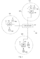
- Figure 1 provides a schematic diagram illustrating some basic functionality of a mobile telecommunications network / system 100 operating in accordance with LTE principles and which may be adapted to implement embodiments of the disclosure as described further below.
- Various elements of Figure 1 and their respective modes of operation are well-known and defined in the relevant standards administered by the 3GPP (RTM) body, and also described in many books on the subject, for example, Holma H. and Toskala A [1]. It will be appreciated that operational aspects of the telecommunications network which are not specifically described below may be implemented in accordance with any known techniques, for example according to the relevant standards.
- the network 100 includes a plurality of base stations 101 connected to a core network 102.
- Each base station provides a coverage area 103 (i.e. a cell) within which data can be communicated to and from communications devices 104.
- Data is transmitted from base stations 101 to communications devices 104 within their respective coverage areas 103 via a radio downlink.
- Data is transmitted from communications devices 104 to the base stations 101 via a radio uplink.
- the uplink and downlink communications are made using radio resources that are licenced for exclusive use by the operator of the network 100.
- the core network 102 routes data to and from the communications devices 104 via the respective base stations 101 and provides functions such as authentication, mobility management, charging and so on.
- a communications device may also be referred to as a mobile station, user equipment (UE), user device, mobile radio, terminal device and so forth.
- a base station may also be referred to as a transceiver station, NodeB, eNodeB (eNB for short), infrastructure equipment and so forth.
- Wireless communications systems such as those arranged in accordance with the 3GPP defined Long Term Evolution (LTE) architecture use an orthogonal frequency division modulation (OFDM) based interface for the radio downlink (so-called OFDMA) and a single carrier frequency division multiple access scheme (SC-FDMA) on the radio uplink.
- OFDM orthogonal frequency division modulation
- SC-FDMA single carrier frequency division multiple access scheme
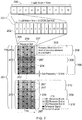
- FIG 2 provides a simplified schematic diagram of the structure of a downlink of a wireless access interface that may be provided by or in association with the eNB of Figure 1 when the communications system is operating in accordance with the LTE standard.
- the wireless access interface of the downlink from an eNB to a UE is based upon an orthogonal frequency division multiplexing (OFDM) access radio interface.
- OFDM orthogonal frequency division multiplexing
- the resources of the available bandwidth are divided in frequency into a plurality of orthogonal subcarriers and data is transmitted in parallel on a plurality of orthogonal subcarriers, where bandwidths between 1.4MHz and 20MHz bandwidth may be divided into 128 to 2048 orthogonal subcarriers for example.
- Each subcarrier bandwidth may take any value but in LTE it is conventionally fixed at 15kHz. However it has been proposed in the future [2] [3] to provide also a reduced subcarrier spacing of 3.75 kHz for certain parts of the LTE wireless access interface for either the uplink or the downlink or both.
- the resources of the wireless access interface are also temporally divided into frames where a frame 200 lasts 10ms and is subdivided into 10 subframes 201 each with a duration of 1ms.
- Each subframe is formed from 14 OFDM symbols and is divided into two slots each of which comprise six or seven OFDM symbols depending on whether a normal or extended cyclic prefix is being utilised between OFDM symbols for the reduction of inter symbol interference.
- the resources within a slot may be divided into resources blocks 203 each comprising 12 subcarriers for the duration of one slot and the resources blocks further divided into resource elements 204 which span one subcarrier for one OFDM symbol, where each rectangle 204 represents a resource element. More details of the down-link structure of the LTE wireless access interface are provided in Annex 1.
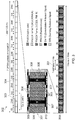
- Figure 3 provides a simplified schematic diagram of the structure of an uplink of an LTE wireless access interface that may be provided by or in association with the eNB of Figure 1 .
- the uplink wireless access interface is based upon a single carrier frequency division multiplexing FDM (SC-FDM) interface and downlink and uplink wireless access interfaces may be provided by frequency division duplexing (FDD) or time division duplexing (TDD), where in TDD implementations subframes switch between uplink and downlink subframes in accordance with predefined patterns.
- FDD frequency division duplexing
- TDD time division duplexing
- a common uplink frame structure is utilised.
- the simplified structure of Figure 3 illustrates such an uplink frame in an FDD implementation.
- a frame 300 is divided in to 10 subframes 301 of 1ms duration where each subframe 301 comprises two slots 302 of 0.5ms duration.
- Each slot is then formed from seven OFDM symbols 303 where a cyclic prefix 304 is inserted between each symbol in a manner equivalent to that in downlink subframes.
- a normal cyclic prefix is used and therefore there are seven OFDM symbols within a subframe, however, if an extended cyclic prefix were to be used, each slot would contain only six OFDM symbols.
- the resources of the uplink subframes are also divided into resource blocks and resource elements in a similar manner to downlink subframes. More details of the LTE up-link represented in Figure 3 are provided in Annex 1.
- NB-IoT Narrowband Internet of Things
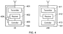
- Figure 4 provides an example schematic block diagram of a terminal device or UE 104 and a infrastructure equipment or eNB 101.
- the UE 104 includes a transmitter 401 and a receiver 402 (which together form a transceiver) which are controlled by a controller 403.
- Storage 404 is also provided.
- the eNB 101 includes a transmitter 411 and a receiver 412 (which together form a transceiver) which are controlled by a controller 413 (which can also implement a scheduler function).
- the UE 104 transmits and receives signals to and from the eNB 101 via a wireless access interface provided by the eNB as part of the wireless communications network.
- Each of the UE 104 and eNB 101 are configured to exchange signals with each other using NB-IoT.
- NB-IOT devices can support cell reselection. They do not need to support network initiated handover procedure. When supporting cell reselection, the UE 104 needs to perform measurements on neighbouring cells. The neighbouring cells can either be on the same frequency (UE 104 performs intra-frequency cell reselection) or on a different frequency (UE 104 performs inter-frequency cell reselection).
- use-cases for the provision of measurements from the UE 104 to the network have been identified.
- Some of these use-cases include network planning and configuration for, in particular and not limited to, intra and inter frequency neighbour cell information, re-direction with RRC connection release to enable load balancing, and positioning for such applications as device tracking and the like. These are referenced in [3]
- measurement information cannot be sent to the network without first having activated AS level security (ciphering, integrity protection) in order to avoid potentially disclosing any UE location related information conveyed in the Measurement reports, such as reference signal received power (RSRP) measurements of neighbour cells which could be used for example for RF fingerprint matching.
- AS level security ciphering, integrity protection
- RSRP reference signal received power
- NB-IoT there are two mechanisms for exchanging data; the user plane solution and the control plane solution. Both of these mechanisms are known to the skilled person.
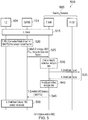
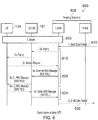
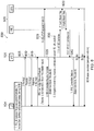
- the control plane solution is described in relation to Figures 5 and 6 and the user plane solution is described with reference to Figure 7 . However, the pertinent points are noted below.
- NB-IoT devices Although it is desirable to send measurement information such as the RSRP for self optimising networks, positioning, or radio resource management, or other data such as battery data, diagnostic information about the device, or other ancillary information relating to either the network or about the status of the terminal device or the user of the terminal device, to the network.
- measurement information such as the RSRP for self optimising networks, positioning, or radio resource management, or other data such as battery data, diagnostic information about the device, or other ancillary information relating to either the network or about the status of the terminal device or the user of the terminal device.
- the narrow bandwidth and small battery size of NB-IoT devices means that this ancillary information should be sent only when necessary. More generally, although this is particularly relevant to NB-IoT devices, the desire to reduce battery consumption and use bandwidth more efficiently is applicable to any kind of terminal device and wireless network.
- a system 500 is shown to explain the control plane solution where data originates at the UE 104.
- the control plane solution is understood by the skilled person.
- the UE 104 is shown connected to eNB 101.
- the eNB then communicates with the network 500.
- the UE 104 attaches to the network in 515.
- the UE 104 connects to the eNB 101 in 520 and the eNB 101 passes this to the network in 525.
- the integrity of the data and decryption is performed by the network in 530 and is communicated to the remainder of the network.
- a reply is subsequently received from the network.
- the data communication within the network is indicated as 535.
- the reply is encrypted by the network in 540 and is passed to the eNB 101 in 545.
- the reply is passed to the UE 104 and the connection between the eNB 101 and the UE 104 is released in 550.
- a system 600 is shown to explain the control plane solution where the data terminates at the UE 104.
- the UE 104 is shown connected to eNB 101.
- the eNB 101 then communicates with the network 500 in step 605.
- Data is passed to the network in step 610.
- the network passes the data to the eNB 101 and the eNB 101 forwards this to the UE 104.
- the UE 104 passes a corresponding service request back to the network (via the eNB 101). This is step 615 in Figure 6 .
- the network passes the downlink NAS message to the eNB 101 which is subsequently forwarded to the UE 104 as a RRC message in step 620.
- the UE 104 passes an uplink RRC message to the eNB 101 that is subsequently passed to the network in step 625.
- the network passes the data into the network in step 630.
- Figure 7 shows a proposed enhancement 700 to the user plane solution which would be known to the skilled person.
- this enhancement allows the UE 104 to connect more quickly to the network with less signal overhead by suspending the connection rather than terminating the connection completely.
- the suspend signalling is shown in 705, the resume is shown in 715 and a known resume with fallback to setup is shown in 710.
- FIG. 8 explains the user plane solution where the data originates at the UE 104.
- a random access preamble 805 is selected by the UE 104.
- the random access preamble is selected from a set of preambles provided by the network. This is sent to the eNB 101 in 805.
- the eNB 101 replies to the random access preamble in 810.
- the UE 104 sends a RRC connection resume request (assuming that the UE 104 is suspended) or an RRC connection request (if the UE 104 is operating in idle mode). This is step 815.
- uplink data to be communicated to the network is sent in 820.
- An RRC connection resume complete signal is sent between the eNB 101 and the UE 104. Up to this point, the data between the UE 104 and the eNB is not encrypted. Transmission of encrypted data is enabled in 830. The transfer of data between the UE 104 and the eNB 101 occurs in 835 and the connection is suspended again in 840.
- FIG. 9 explains the user plane solution where the data terminates at the UE 104.
- the data is sent across the network in steps 905, 910 and 915.
- the eNB 101 pages the UE 104 in 920.
- the RRC resume procedure is commenced at step 925.
- the UE 104 selects a random access preamble from a set of preambles provided by the network in 930.
- the eNB 101 replies to the random access preamble in 935.
- the UE 104 sends a RRC connection resume request (assuming that the UE 104 is suspended) or an RRC connection request (if the UE 104 is operating in idle mode). This is step 940.
- An RRC connection resume complete signal is sent between the eNB 101 and the UE 104 in step 945. Encryption is enabled at this point (step 950).
- Various network signalling then takes place in step 955 followed by downlink and uplink data in step 960.
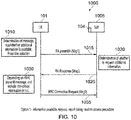
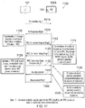
- Figure 10 explains a signalling diagram 1000 according to embodiments of the disclosure.
- a first option is shown.
- the network 1005 includes eNB 104, but also other parts of the infrastructure. This nomenclature is for ease of reference.
- the UE 101 takes measurements. These measurements may include the RSRP or RSRQ, the signal strength or quality of the current cell or neighbouring cells and other measurements relating to the network environment. Other additional measurements such as position information of the UE 101 and the like may also be taken. These measurements are not critical to every connection between the network 1005 and the UE 101. In other words, failure to provide these measurements to the network will not terminate the connection between the UE 101 and the network 1005. These measurements are examples of ancillary data which may be provided to the network. Other examples of the ancillary data include home energy readings if the NB-IoT device is a smart meter, personal health information of the user if the NB-IoT is a fitness band, battery life remaining or the like. In other words, the ancillary data is not limited to data pertaining to a measurement.
- the eNB 104 may redirect the UE 101 to a different eNB if the reported RSRP value of that cell is above a threshold. However, the connection between the UE 101 and the network 1005 would not be terminated if the UE 101 was not diverted to the different eNB.
- This ancillary data is stored within storage 404 within the UE 104.
- a random access preamble is selected from a set of random access preambles provided by the network. This is explained with reference to Figures 5 and 8 for the control plane solution and the user plane solution respectively.
- the network allocates specific ones of the set of random access preambles to indicate that the UE 104 has ancillary data that is not critical to the connection. This random access preamble may simply indicate that the UE 104 has ancillary data to transmit.
- the selection of the preamble may also indicate the size of the ancillary data. For example, for an RSRP measurement, only a small amount of data would be required. However, other forms of ancillary data may be larger, such as signal quality information for all received carriers. In this case, the UE 104 will select the random access preamble according to the size of the ancillary data. By selecting the preamble in this manner, the network understands when the ancillary data should be transferred.
- the first (critical) part of the message would always be below the threshold, so UE 104 would select from a preamble set A if there is no additional information, or if the additional information does not cause the message size threshold to be exceeded. If the additional information causes the message size threshold to be exceeded, then the UE 104 would select from preamble set B.
- the controller 413 determines, firstly whether the storage 404 contains the ancillary data. The controller 413 may also determine the size of the ancillary data. On this basis, an appropriate random preamble is selected in step 1010. The selected preamble is sent to the network 1005 via the eNB 104 in the Random Access Preamble in 1015 (noted in step 515 in Figure 5 ; 605 in Figure 6 ; 805 in Figure 8 and 930 in Figure 9 ).
- the network 1005 decides at step 1020 whether the ancillary data should be transmitted by the UE 104. This decision may be based on the congestion on the cell upon which the UE 104 is to be re-directed. If the network 1005 has high levels of congestion on the cell, the network may request the UE 104 provides the RSRP measurement of neighbouring cells. This allows the network to provide better traffic management. Alternatively, the network 1005 may determine that the UE 104 should transmit the energy consumption of a household at a particular point in the day, for example, when the energy provider's servers are less busy.
- the network 1005 (via the eNB 101) provides a random access response (RAR) indicating whether the additional information should be sent or not.
- the random access response is step 1025 in Figure 10 , part of step 515 in Figure 5 ; step 605 in Figure 6 , 810 in Figure 8 and 935 in Figure 9 .
- This indication informs the UE 104 which message size to use as well as which resources or random access channel to send the ancillary information on.
- the indication provided by the network may tell the UE 104 the format in which to send the ancillary data.
- the network 1005 may inform the UE 104 to send just the cell ID (which is a shorter message) if that is all the network 1005 requires.
- the network may request other information such as RSRP values which is a longer message, but contains different information useful to the network 1005.
- the network 1005 may instruct the UE 104 to use either the user plane solution or the control plane solution.
- the controller of the UE 104 would control the transmitter to set up a connection with the network 1005 which allows transmission of the ancillary data by piggybacking this data on a control plane message.
- the controller of the UE 104 would configure the transmitter to set up a connection with a dedicated user plane radio bearer for transmitting the ancillary data.
- the UE 104 may receive from the network 1005 an indication of the type and format of the message which is to convey the ancillary data.
- the UE 104 determines whether to transmit the ancillary information. This is step 1030. Depending on the indication from the network 1005, the UE 104 may decide to send particular ancillary data or ancillary data in a particular format. The ancillary data is then sent on the RRC connection request in step 1035 if the size of ancillary data is small enough. Of course, in the event that the UE is using the resume procedure, the ancillary data will be sent on the RRC connection resume request.
- network 1005 includes the eNB 104.
- the determination of the presence of the ancillary data is performed in step 1105.
- the UE 104 determines the presence of the ancillary data after the UE 104 receives the random access response. The determination by the UE 104 is the same as explained with reference to option 1 above.
- the indication instead of being made using a random access preamble as in option 1, the indication is made in the RRC connection request, or resume message.
- the determination by the network 1005 is the same as explained above as to whether, and of what type of ancillary data, the network requires. This is step 1115.
- This determination response from the network 1005 is sent in the RRC connection setup or resume message in step 1120.
- the UE 104 determines whether to transmit the ancillary information. This is step 1125. Depending on the indication from the network 1005, the UE 104 may decide to send particular ancillary data or ancillary data in a particular format. The ancillary data is then sent on the RRC connection setup complete message in step 1130.
- the RRC connection setup complete message may be used to transmit the small sized ancillary data, such as cell IDs or cells meeting a threshold. However for other ancillary data such as RSRP measurement data (which are larger in size and should be sent securely to not allow a third party to establish the location of the UE 104), then the ancillary data may be sent in a later message.
- the network 1005 it is possible for the network 1005 to also indicate to the UE 104 whether to use the user plane or the control plane solution. For example, if the network 1005 decides to retrieve only the critical information then the control plane can be used. However, if the network 1005 wants to retrieve ancillary data that is measurement data for positioning or another purpose, then the user plane solution may be activated. Similarly, as explained above, for the smart-meter example, then the user plane solution may be activated as security is required.
- the choice of message in which to send the ancillary information depends on the type of data as well as the size of data to be sent. For example, a short measurement report may be sent in step 1130 in the RRC connection setup complete message. However, a longer report of ancillary data such as one including RSRP measurements would be sent in a measurement report (step 1150). Given the content of the RSRP measurement data (which includes position information), the measurement report is sent after the activation of security in step 1140.
- a third option is also envisaged.
- the third option is a combination of options land 2 and determines in which position within the signal diagram to send ancillary message. Specifically, if the ancillary data to be transferred fits within the RRC connection request and no security is required, the ancillary information is transferred on the RRC connection request. Alternatively, if the ancillary message is larger than the RRC connection request, but is smaller than the RRC connection setup complete message and no security is required, then the ancillary data is sent in the RRC connection setup complete message and the control plane solution is required. Alternatively, if the ancillary data is larger than the RRC connection setup complete message or the ancillary data requires security, then the user plane solution is selected and the ancillary data is sent as a separate message after the security activation step 1140.
- Described embodiments may be implemented in any suitable form including hardware, software, firmware or any combination of these. Described embodiments may optionally be implemented at least partly as computer software running on one or more data processors and/or digital signal processors.
- the elements and components of any embodiment may be physically, functionally and logically implemented in any suitable way. Indeed the functionality may be implemented in a single unit, in a plurality of units or as part of other functional units. As such, the disclosed embodiments may be implemented in a single unit or may be physically and functionally distributed between different units, circuitry and/or processors.
- the simplified structure of the downlink of an LTE wireless access interface presented in Figure 2 also includes an illustration of each subframe 201, which comprises a control region 205 for the transmission of control data, a data region 206 for the transmission of user data, reference signals 207 and synchronisation signals which are interspersed in the control and data regions in accordance with a predetermined pattern.
- the control region 204 may contain a number of physical channels for the transmission of control data, such as a physical downlink control channel PDCCH, a physical control format indicator channel PCFICH and a physical HARQ indicator channel PHICH.
- the data region may contain a number of physical channel for the transmission of data, such as a physical downlink shared channel PDSCH and a physical broadcast channels PBCH. Although these physical channels provide a wide range of functionality to LTE systems, in terms of resource allocation and the present disclosure PDCCH and PDSCH are most relevant. Further information on the structure and functioning of the physical channels of LTE systems can be found in [1].
- Resources within the PDSCH may be allocated by an eNodeB to UEs being served by the eNodeB. For example, a number of resource blocks of the PDSCH may be allocated to a UE in order that it may receive data that it has previously requested or data which is being pushed to it by the eNodeB, such as radio resource control RRC signalling.
- UE1 has been allocated resources 208 of the data region 206, UE2 resources 209 and UE resources 210.
- UEs in a an LTE system may be allocated a fraction of the available resources of the PDSCH and therefore UEs are required to be informed of the location of their allocated resources within the PDCSH so that only relevant data within the PDSCH is detected and estimated.
- resource control information specifying downlink resource allocations is conveyed across the PDCCH in a form termed downlink control information DCI, where resource allocations for a PDSCH are communicated in a preceding PDCCH instance in the same subframe.
- DCI downlink control information
- UEs monitor the PDCCH for DCI addressed to them and once such a DCI is detected, receive the DCI and detect and estimate the data from the relevant part of the PDSCH.
- Each uplink subframe may include a plurality of different channels, for example a physical uplink shared channel PUSCH 305, a physical uplink control channel PUCCH 306, and a physical random access channel PRACH.
- the physical Uplink Control Channel PUCCH may carry control information such as ACK/NACK to the eNodeB for downlink transmissions, scheduling request indicators SRI for UEs wishing to be scheduled uplink resources, and feedback of downlink channel state information CSI for example.
- the PUSCH may carry UE uplink data or some uplink control data. Resources of the PUSCH are granted via PDCCH, such a grant being typically triggered by communicating to the network the amount of data ready to be transmitted in a buffer at the UE.
- the PRACH may be scheduled in any of the resources of an uplink frame in accordance with a one of a plurality of PRACH patterns that may be signalled to UE in downlink signalling such as system information blocks.
- uplink subframes may also include reference signals.
- demodulation reference signals DMRS 307 and sounding reference signals SRS 308 may be present in an uplink subframe where the DMRS occupy the fourth symbol of a slot in which PUSCH is transmitted and are used for decoding of PUCCH and PUSCH data, and where SRS are used for uplink channel estimation at the eNodeB. Further information on the structure and functioning of the physical channels of LTE systems can be found in [1].
- resources of the PUSCH are required to be scheduled or granted by the serving eNodeB and thus if data is to be transmitted by a UE, resources of the PUSCH are required to be granted to the UE by the eNode B.
- PUSCH resource allocation is achieved by the transmission of a scheduling request or a buffer status report to its serving eNodeB.
- the scheduling request may be made, when there is insufficient uplink resource for the UE to send a buffer status report, via the transmission of Uplink Control Information UCI on the PUCCH when there is no existing PUSCH allocation for the UE, or by transmission directly on the PUSCH when there is an existing PUSCH allocation for the UE.
- the eNodeB In response to a scheduling request, the eNodeB is configured to allocate a portion of the PUSCH resource to the requesting UE sufficient for transferring a buffer status report and then inform the UE of the buffer status report resource allocation via a DCI in the PDCCH.
- the buffer status report is sent to the eNodeB and gives the eNodeB information regarding the amount of data in an uplink buffer or buffers at the UE.
- the eNodeB can allocate a portion of the PUSCH resources to the sending UE in order to transmit some of its buffered uplink data and then inform the UE of the resource allocation via a DCI in the PDCCH.
- the UE presuming a UE has a connection with the eNodeB, the UE will first transmit a PUSCH resource request in the PUCCH in the form of a UCI. The UE will then monitor the PDCCH for an appropriate DCI, extract the details of the PUSCH resource allocation, and transmit uplink data, at first comprising a buffer status report, and/or later comprising a portion of the buffered data, in the allocated resources.
- uplink subframes have a different control structure to downlink subframes, in particular the upper 309 and lower 310 subcarriers/frequencies/resource blocks of an uplink subframe are reserved for control signaling rather than the initial symbols of a downlink subframe.
- the resource allocation procedure for the downlink and uplink are relatively similar, the actual structure of the resources that may be allocated may vary due to the different characteristics of the OFDM and SC-FDM interfaces that are used in the downlink and uplink respectively.
- each subcarrier is individually modulated and therefore it is not necessary that frequency/subcarrier allocation are contiguous however, in SC-FDM subcarriers are modulation in combination and therefore if efficient use of the available resources are to be made contiguous frequency allocations for each UE are preferable.
- one or more UEs may communicate data to one another via a coordinating eNodeB, thus forming a conventional cellular telecommunications system.
- cellular communications system such as those based on the previously released LTE standards have been commercially successful, a number of disadvantages are associated with such centralised systems. For example, if two UEs which are in close proximity wish to communicate with each other, uplink and downlink resources sufficient to convey the data are required. Consequently, two portions of the system's resources are being used to convey a single portion of data.
- a second disadvantage is that an eNodeB is required if UEs, even when in close proximity, wish to communicate with one another.
Landscapes
- Engineering & Computer Science (AREA)
- Computer Networks & Wireless Communication (AREA)
- Signal Processing (AREA)
- Mobile Radio Communication Systems (AREA)
Claims (8)
- Endgerätevorrichtung (104) zur Verwendung mit einem drahtlosen Telekommunikationsnetz, wobei die Endgerätevorrichtung umfasst:einen Speicher (404), der dazu ausgelegt ist, Zusatzinformationen zu speichern, die nicht für jede Verbindung zwischen der Endgerätevorrichtung und dem drahtlosen Telekommunikationsnetz wesentlich sind;eine Steuerung (403), die dazu ausgelegt ist, Daten zu erzeugen, die für die gespeicherten Zusatzinformationen kennzeichnend sind;einen Sender (401), der dazu ausgelegt ist, die erzeugten Daten an das drahtlose Telekommunikationsnetzwerk zu übertragen; undeinen Empfänger (402), der dazu ausgelegt ist, eine Angabe von dem drahtlosen Telekommunikationsnetz zu empfangen, ob die Zusatzinformationen zu dem drahtlosen Telekommunikationsnetz übertragen werden sollen, wobei der Sender als Reaktion auf die Angabe dazu ausgelegt ist, die Zusatzinformationen zu übertragen; wobei die erzeugten Daten eine Präambel sind und die Steuerung dazu ausgelegt ist, die Präambel basierend auf der Größe der gespeicherten Zusatzinformationen auszuwählen, so dass eine erste Präambel in dem Fall ausgewählt wird, dass die Größe der gespeicherten Zusatzinformationen bei oder unter einem ersten Schwellenwert liegt, und dass eine zweite, andere Präambel in dem Fall ausgewählt wird, dass die Größe der gespeicherten Zusatzinformationen über dem ersten Schwellenwert liegt.
- Endgerätevorrichtung nach Anspruch 1, wobei die Steuerung ferner dazu ausgelegt ist, einen Signalparameter des drahtlosen Telekommunikationsnetzes zu messen, und die Zusatzinformationen Messdaten sind, die durch die Endgerätevorrichtung gemessen werden.
- Endgerätevorrichtung nach Anspruch 1, wobei die Endgerätevorrichtung eine Narrow Band Internet of Things, NB-IoT, Endgerätevorrichtung ist.
- Endgerätevorrichtung nach Anspruch 1, wobei der Empfänger ferner dazu ausgelegt ist, von dem drahtlosen Telekommunikationsnetz eine Angabe über den Typ und das Format der Nachricht zu empfangen, die die Zusatzinformationen übermitteln soll.
- Infrastrukturausrüstung (101) zur Verwendung mit einem drahtlosen Telekommunikationsnetz, wobei die Infrastrukturausrüstung umfasst:einen Empfänger (412), der dazu ausgelegt ist, kennzeichnende Daten von einer Endgerätevorrichtung zu empfangen, die angeben, dass die Endgerätevorrichtung Zusatzinformationen gespeichert hat, die nicht für jede Verbindung zwischen der Endgerätevorrichtung und dem drahtlosen Telekommunikationsnetz wesentlich sind;eine Steuerung (413), die dazu ausgelegt ist, zu bestimmen, ob die Zusatzinformationen von der Endgerätevorrichtung angefordert werden sollen; undeinen Sender (411), der unter der Kontrolle der Steuerung steht und dazu ausgelegt ist, eine Anforderung für die gespeicherten Zusatzinformationen zu übertragen; wobei der Empfänger dazu ausgelegt ist, die Zusatzinformationen zu empfangen; wobei die kennzeichnenden Daten eine Präambel umfassen und die Steuerung dazu ausgelegt ist, zu bestimmen, ob die Zusatzdaten gemäß der empfangenen Präambel anzufordern sind; wobei eine erste Präambel in dem Fall empfangen wird, dass die Größe der gespeicherten Zusatzinformationen bei oder unter einem ersten Schwellenwert liegt, und dass eine zweite, andere Präambel in dem Fall empfangen wird, dass die Größe der gespeicherten Zusatzinformationen über dem ersten Schwellenwert liegt.
- Infrastrukturausrüstung nach Anspruch 5, wobei die Zusatzinformationen Messdaten sind, die durch die Endgerätevorrichtung gemessen werden.
- Verfahren zum Betreiben einer Endgerätevorrichtung (104) zur Verwendung mit einem drahtlosen Telekommunikationsnetz, wobei das Verfahren umfasst:Speichern von Zusatzinformationen, die nicht für jede Verbindung zwischen der Endgerätevorrichtung und dem drahtlosen Telekommunikationsnetz wesentlich sind;Erzeugen von Daten, die für die gespeicherten Zusatzinformationen kennzeichnend sind;Übertragen der erzeugten Daten in das drahtlose Telekommunikationsnetz;Empfangen einer Angabe von dem drahtlosen Telekommunikationsnetz, ob die Zusatzinformationen an das drahtlose Telekommunikationsnetz übertragen werden sollen, wobei als Reaktion auf die Angabe; undÜbertragen der Zusatzinformationen; wobei die erzeugten Daten eine Präambel sind und das Verfahren das Auswählen der Präambel basierend auf der Größe der gespeicherten Zusatzinformationen umfasst, so dass eine erste Präambel ausgewählt wird, wenn die Größe der gespeicherten Zusatzinformationen bei oder unter einem ersten Schwellenwert liegt, und dass eine zweite, andere Präambel ausgewählt wird, wenn die Größe der gespeicherten Zusatzinformationen über dem ersten Schwellenwert liegt.
- Verfahren zum Steuern einer Infrastrukturausrüstung (101) zur Verwendung mit einem drahtlosen Telekommunikationsnetz, wobei das Verfahren umfasst:Empfangen kennzeichnender Daten von einer Endgerätevorrichtung, die angeben, dass die Endgerätevorrichtung Zusatzinformationen gespeichert hat, die nicht für jede Verbindung zwischen der Endgerätevorrichtung und dem drahtlosen Telekommunikationsnetz wesentlich sind;Bestimmen, ob die Zusatzinformationen von der Endgerätevorrichtung anzufordern sind; und Übertragen einer Anforderung für die gespeicherten Zusatzinformationen; wobei der Empfänger dazu ausgelegt ist, die Zusatzinformationen zu empfangen; wobei die kennzeichnenden Daten eine Präambel umfassen und das Verfahren das Bestimmen umfasst, ob die Zusatzdaten gemäß der empfangenen Präambel anzufordern sind; wobei eine erste Präambel für den Fall empfangen wird, dass die Größe der gespeicherten Zusatzinformationen bei oder unter einem ersten Schwellenwert liegt, und dass eine zweite, unterschiedliche Präambel für den Fall empfangen wird, dass die Größe der gespeicherten Zusatzinformationen über dem ersten Schwellenwert liegt.
Applications Claiming Priority (2)
| Application Number | Priority Date | Filing Date | Title |
|---|---|---|---|
| EP16155580 | 2016-02-12 | ||
| PCT/EP2017/051086 WO2017137230A1 (en) | 2016-02-12 | 2017-01-19 | Terminal device, infrastructure equipment, methods and integrated circuitry |
Publications (3)
| Publication Number | Publication Date |
|---|---|
| EP3403461A1 EP3403461A1 (de) | 2018-11-21 |
| EP3403461B1 true EP3403461B1 (de) | 2021-07-07 |
| EP3403461B8 EP3403461B8 (de) | 2021-10-06 |
Family
ID=55435981
Family Applications (1)
| Application Number | Title | Priority Date | Filing Date |
|---|---|---|---|
| EP17700575.8A Active EP3403461B8 (de) | 2016-02-12 | 2017-01-19 | Endgerätevorrichtung, infrastrukturausrüstung und verfahren |
Country Status (3)
| Country | Link |
|---|---|
| US (4) | US11153910B2 (de) |
| EP (1) | EP3403461B8 (de) |
| WO (1) | WO2017137230A1 (de) |
Families Citing this family (8)
| Publication number | Priority date | Publication date | Assignee | Title |
|---|---|---|---|---|
| EP3403461B8 (de) * | 2016-02-12 | 2021-10-06 | Sony Group Corporation | Endgerätevorrichtung, infrastrukturausrüstung und verfahren |
| EP3934365B1 (de) * | 2016-08-16 | 2024-01-17 | Guangdong Oppo Mobile Telecommunications Corp., Ltd. | Verfahren und vorrichtung zur informationsübertragung |
| US11032673B2 (en) * | 2016-08-30 | 2021-06-08 | Kyocera Corporation | Radio terminal and base station |
| KR20180035638A (ko) * | 2016-09-29 | 2018-04-06 | 삼성전자주식회사 | RRC Inactive 및 active 상태에서 data 전송 결정 및 방법 및 장치 |
| FR3065138B1 (fr) * | 2017-04-05 | 2020-12-11 | Sigfox | Systeme de communication sans fil comportant un canal physique d’acces aleatoire global dans le temps et l’espace |
| JP2020530725A (ja) * | 2017-08-11 | 2020-10-22 | ホアウェイ・テクノロジーズ・カンパニー・リミテッド | データ送信方法及びデバイス |
| CN107689995B (zh) * | 2017-08-31 | 2020-01-10 | 浙江大学 | 一种基于nb-iot技术的电动汽车电池无线管理系统及方法 |
| EP3462797A1 (de) * | 2017-09-28 | 2019-04-03 | Panasonic Intellectual Property Corporation of America | Benutzergerät und basisstation mit beteiligung am priorisierten direktzugriff |
Family Cites Families (14)
| Publication number | Priority date | Publication date | Assignee | Title |
|---|---|---|---|---|
| CN102149214B (zh) * | 2010-02-05 | 2015-05-13 | 中兴通讯股份有限公司 | 一种通信系统中的数据传输方法和系统 |
| US8644204B2 (en) * | 2010-03-05 | 2014-02-04 | Industrial Technology Research Institute | Systems and methods for operation mode transition in wireless communications |
| US8681701B2 (en) * | 2010-06-03 | 2014-03-25 | Via Telecom Co., Ltd. | Mobile communications devices and transmission methods for transmitting machine type communication data thereof |
| US20110317636A1 (en) * | 2010-06-24 | 2011-12-29 | John Diachina | Channel requests for machine-type devices |
| MX2013007940A (es) * | 2011-01-07 | 2013-11-01 | Fujitsu Ltd | Metodo para activar un simbolo de referencia de sondeo aperiodico, estacion base y equipo de usuario. |
| GB2489690B (en) * | 2011-04-01 | 2013-03-20 | Renesas Mobile Corp | Small data transmission for detached mobile devices |
| US9025455B2 (en) * | 2011-04-26 | 2015-05-05 | Industrial Technology Research Institute | Prioritized random access method, resource allocation method and collision resolution method |
| US8879667B2 (en) * | 2011-07-01 | 2014-11-04 | Intel Corporation | Layer shifting in open loop multiple-input, multiple-output communications |
| CN104756589A (zh) | 2012-08-03 | 2015-07-01 | 美国博通公司 | 用于测量报告的方法与设备 |
| US9955373B2 (en) * | 2012-11-05 | 2018-04-24 | Telefonaktiebolaget L M Ericsson (Publ) | Systems and methods for controlling logging and reporting under constraints |
| JP6110739B2 (ja) * | 2013-06-25 | 2017-04-05 | 京セラ株式会社 | 通信制御方法、ユーザ端末、及びプロセッサ |
| WO2015200804A1 (en) * | 2014-06-27 | 2015-12-30 | Intel IP Corporation | Methods apparatus of enb and ue for mtc with narrowband deployment |
| WO2017108111A1 (en) * | 2015-12-22 | 2017-06-29 | Sony Mobile Communications Inc. | Co-deployment of narrowband and wideband carriers |
| EP3403461B8 (de) * | 2016-02-12 | 2021-10-06 | Sony Group Corporation | Endgerätevorrichtung, infrastrukturausrüstung und verfahren |
-
2017
- 2017-01-19 EP EP17700575.8A patent/EP3403461B8/de active Active
- 2017-01-19 US US16/077,282 patent/US11153910B2/en not_active Expired - Fee Related
- 2017-01-19 WO PCT/EP2017/051086 patent/WO2017137230A1/en not_active Ceased
-
2021
- 2021-10-18 US US17/503,423 patent/US11838954B2/en active Active
-
2023
- 2023-12-04 US US18/527,519 patent/US20240107589A1/en not_active Abandoned
- 2023-12-04 US US18/527,591 patent/US20240107590A1/en not_active Abandoned
Non-Patent Citations (1)
| Title |
|---|
| None * |
Also Published As
| Publication number | Publication date |
|---|---|
| US20220039173A1 (en) | 2022-02-03 |
| US20190053285A1 (en) | 2019-02-14 |
| US20240107589A1 (en) | 2024-03-28 |
| US11153910B2 (en) | 2021-10-19 |
| EP3403461A1 (de) | 2018-11-21 |
| EP3403461B8 (de) | 2021-10-06 |
| WO2017137230A1 (en) | 2017-08-17 |
| US20240107590A1 (en) | 2024-03-28 |
| US11838954B2 (en) | 2023-12-05 |
Similar Documents
| Publication | Publication Date | Title |
|---|---|---|
| US12464535B2 (en) | Methods, devices, and apparatuses for beam management | |
| US12588055B2 (en) | Random access response reception | |
| US11838954B2 (en) | Terminal device, infrastructure equipment, methods and integrated circuitry | |
| US11737149B2 (en) | Random access procedure based on contention resolution | |
| US12082247B2 (en) | Resource selection using a listen before talk procedure | |
| US11985706B2 (en) | Access procedures for wireless communications | |
| JP7284968B2 (ja) | 新無線における多重化および優先順位付け | |
| JP7284884B2 (ja) | 無認可帯域における2段階ランダムアクセス手順 | |
| US11805498B2 (en) | Flexible multiplexing of users with difference requirements in a 5G frame structure | |
| JP6924460B2 (ja) | スケジューリング要求ベースのビーム障害回復 | |
| CN111711982B (zh) | 用于设备到设备通信的通信装置及方法 | |
| US10455487B2 (en) | Repetitive transmission for NB-IoT | |
| KR20210042353A (ko) | 광대역폭을 위한 셀 및 채널 액세스 | |
| EP2983425A1 (de) | D2D-Datenübertragung - Zeitvorlauf für Ruhemodus-Benutzergerät | |
| CN110999125A (zh) | 通信装置、通信控制方法和计算机程序 | |
| TW202241169A (zh) | 經由禁止的無爭用ris切換 | |
| EP3411959B1 (de) | Endgerätvorrichtung, infrastrukturvorrichtung, verfahren und integrierte schaltung |
Legal Events
| Date | Code | Title | Description |
|---|---|---|---|
| STAA | Information on the status of an ep patent application or granted ep patent |
Free format text: STATUS: UNKNOWN |
|
| STAA | Information on the status of an ep patent application or granted ep patent |
Free format text: STATUS: THE INTERNATIONAL PUBLICATION HAS BEEN MADE |
|
| PUAI | Public reference made under article 153(3) epc to a published international application that has entered the european phase |
Free format text: ORIGINAL CODE: 0009012 |
|
| STAA | Information on the status of an ep patent application or granted ep patent |
Free format text: STATUS: REQUEST FOR EXAMINATION WAS MADE |
|
| 17P | Request for examination filed |
Effective date: 20180813 |
|
| AK | Designated contracting states |
Kind code of ref document: A1 Designated state(s): AL AT BE BG CH CY CZ DE DK EE ES FI FR GB GR HR HU IE IS IT LI LT LU LV MC MK MT NL NO PL PT RO RS SE SI SK SM TR |
|
| AX | Request for extension of the european patent |
Extension state: BA ME |
|
| DAV | Request for validation of the european patent (deleted) | ||
| DAX | Request for extension of the european patent (deleted) | ||
| STAA | Information on the status of an ep patent application or granted ep patent |
Free format text: STATUS: EXAMINATION IS IN PROGRESS |
|
| 17Q | First examination report despatched |
Effective date: 20190712 |
|
| RAP1 | Party data changed (applicant data changed or rights of an application transferred) |
Owner name: SONY MOBILE COMMUNICATIONS, INC. Owner name: SONY CORPORATION Owner name: SONY EUROPE LIMITED |
|
| GRAP | Despatch of communication of intention to grant a patent |
Free format text: ORIGINAL CODE: EPIDOSNIGR1 |
|
| STAA | Information on the status of an ep patent application or granted ep patent |
Free format text: STATUS: GRANT OF PATENT IS INTENDED |
|
| INTG | Intention to grant announced |
Effective date: 20201023 |
|
| RIC1 | Information provided on ipc code assigned before grant |
Ipc: H04W 88/02 20090101ALI20201009BHEP Ipc: H04W 74/08 20090101AFI20201009BHEP |
|
| GRAJ | Information related to disapproval of communication of intention to grant by the applicant or resumption of examination proceedings by the epo deleted |
Free format text: ORIGINAL CODE: EPIDOSDIGR1 |
|
| STAA | Information on the status of an ep patent application or granted ep patent |
Free format text: STATUS: EXAMINATION IS IN PROGRESS |
|
| GRAS | Grant fee paid |
Free format text: ORIGINAL CODE: EPIDOSNIGR3 |
|
| STAA | Information on the status of an ep patent application or granted ep patent |
Free format text: STATUS: GRANT OF PATENT IS INTENDED |
|
| GRAP | Despatch of communication of intention to grant a patent |
Free format text: ORIGINAL CODE: EPIDOSNIGR1 |
|
| INTC | Intention to grant announced (deleted) | ||
| INTG | Intention to grant announced |
Effective date: 20210301 |
|
| GRAA | (expected) grant |
Free format text: ORIGINAL CODE: 0009210 |
|
| STAA | Information on the status of an ep patent application or granted ep patent |
Free format text: STATUS: THE PATENT HAS BEEN GRANTED |
|
| AK | Designated contracting states |
Kind code of ref document: B1 Designated state(s): AL AT BE BG CH CY CZ DE DK EE ES FI FR GB GR HR HU IE IS IT LI LT LU LV MC MK MT NL NO PL PT RO RS SE SI SK SM TR |
|
| REG | Reference to a national code |
Ref country code: GB Ref legal event code: FG4D |
|
| REG | Reference to a national code |
Ref country code: AT Ref legal event code: REF Ref document number: 1409876 Country of ref document: AT Kind code of ref document: T Effective date: 20210715 |
|
| RAP4 | Party data changed (patent owner data changed or rights of a patent transferred) |
Owner name: SONY EUROPE LIMITED Owner name: SONY MOBILE COMMUNICATIONS, INC. Owner name: SONY GROUP CORPORATION |
|
| REG | Reference to a national code |
Ref country code: DE Ref legal event code: R096 Ref document number: 602017041578 Country of ref document: DE |
|
| REG | Reference to a national code |
Ref country code: NL Ref legal event code: FP Ref country code: IE Ref legal event code: FG4D |
|
| REG | Reference to a national code |
Ref country code: SE Ref legal event code: TRGR |
|
| REG | Reference to a national code |
Ref country code: CH Ref legal event code: PK Free format text: BERICHTIGUNG B8 |
|
| RAP4 | Party data changed (patent owner data changed or rights of a patent transferred) |
Owner name: SONY EUROPE LIMITED Owner name: SONY GROUP CORPORATION |
|
| REG | Reference to a national code |
Ref country code: LT Ref legal event code: MG9D |
|
| REG | Reference to a national code |
Ref country code: AT Ref legal event code: MK05 Ref document number: 1409876 Country of ref document: AT Kind code of ref document: T Effective date: 20210707 |
|
| PG25 | Lapsed in a contracting state [announced via postgrant information from national office to epo] |
Ref country code: LT Free format text: LAPSE BECAUSE OF FAILURE TO SUBMIT A TRANSLATION OF THE DESCRIPTION OR TO PAY THE FEE WITHIN THE PRESCRIBED TIME-LIMIT Effective date: 20210707 Ref country code: BG Free format text: LAPSE BECAUSE OF FAILURE TO SUBMIT A TRANSLATION OF THE DESCRIPTION OR TO PAY THE FEE WITHIN THE PRESCRIBED TIME-LIMIT Effective date: 20211007 Ref country code: AT Free format text: LAPSE BECAUSE OF FAILURE TO SUBMIT A TRANSLATION OF THE DESCRIPTION OR TO PAY THE FEE WITHIN THE PRESCRIBED TIME-LIMIT Effective date: 20210707 Ref country code: NO Free format text: LAPSE BECAUSE OF FAILURE TO SUBMIT A TRANSLATION OF THE DESCRIPTION OR TO PAY THE FEE WITHIN THE PRESCRIBED TIME-LIMIT Effective date: 20211007 Ref country code: PT Free format text: LAPSE BECAUSE OF FAILURE TO SUBMIT A TRANSLATION OF THE DESCRIPTION OR TO PAY THE FEE WITHIN THE PRESCRIBED TIME-LIMIT Effective date: 20211108 Ref country code: ES Free format text: LAPSE BECAUSE OF FAILURE TO SUBMIT A TRANSLATION OF THE DESCRIPTION OR TO PAY THE FEE WITHIN THE PRESCRIBED TIME-LIMIT Effective date: 20210707 Ref country code: FI Free format text: LAPSE BECAUSE OF FAILURE TO SUBMIT A TRANSLATION OF THE DESCRIPTION OR TO PAY THE FEE WITHIN THE PRESCRIBED TIME-LIMIT Effective date: 20210707 Ref country code: RS Free format text: LAPSE BECAUSE OF FAILURE TO SUBMIT A TRANSLATION OF THE DESCRIPTION OR TO PAY THE FEE WITHIN THE PRESCRIBED TIME-LIMIT Effective date: 20210707 Ref country code: HR Free format text: LAPSE BECAUSE OF FAILURE TO SUBMIT A TRANSLATION OF THE DESCRIPTION OR TO PAY THE FEE WITHIN THE PRESCRIBED TIME-LIMIT Effective date: 20210707 |
|
| PG25 | Lapsed in a contracting state [announced via postgrant information from national office to epo] |
Ref country code: PL Free format text: LAPSE BECAUSE OF FAILURE TO SUBMIT A TRANSLATION OF THE DESCRIPTION OR TO PAY THE FEE WITHIN THE PRESCRIBED TIME-LIMIT Effective date: 20210707 Ref country code: LV Free format text: LAPSE BECAUSE OF FAILURE TO SUBMIT A TRANSLATION OF THE DESCRIPTION OR TO PAY THE FEE WITHIN THE PRESCRIBED TIME-LIMIT Effective date: 20210707 Ref country code: GR Free format text: LAPSE BECAUSE OF FAILURE TO SUBMIT A TRANSLATION OF THE DESCRIPTION OR TO PAY THE FEE WITHIN THE PRESCRIBED TIME-LIMIT Effective date: 20211008 |
|
| REG | Reference to a national code |
Ref country code: DE Ref legal event code: R097 Ref document number: 602017041578 Country of ref document: DE |
|
| PG25 | Lapsed in a contracting state [announced via postgrant information from national office to epo] |
Ref country code: DK Free format text: LAPSE BECAUSE OF FAILURE TO SUBMIT A TRANSLATION OF THE DESCRIPTION OR TO PAY THE FEE WITHIN THE PRESCRIBED TIME-LIMIT Effective date: 20210707 |
|
| PLBE | No opposition filed within time limit |
Free format text: ORIGINAL CODE: 0009261 |
|
| STAA | Information on the status of an ep patent application or granted ep patent |
Free format text: STATUS: NO OPPOSITION FILED WITHIN TIME LIMIT |
|
| PG25 | Lapsed in a contracting state [announced via postgrant information from national office to epo] |
Ref country code: SM Free format text: LAPSE BECAUSE OF FAILURE TO SUBMIT A TRANSLATION OF THE DESCRIPTION OR TO PAY THE FEE WITHIN THE PRESCRIBED TIME-LIMIT Effective date: 20210707 Ref country code: SK Free format text: LAPSE BECAUSE OF FAILURE TO SUBMIT A TRANSLATION OF THE DESCRIPTION OR TO PAY THE FEE WITHIN THE PRESCRIBED TIME-LIMIT Effective date: 20210707 Ref country code: RO Free format text: LAPSE BECAUSE OF FAILURE TO SUBMIT A TRANSLATION OF THE DESCRIPTION OR TO PAY THE FEE WITHIN THE PRESCRIBED TIME-LIMIT Effective date: 20210707 Ref country code: EE Free format text: LAPSE BECAUSE OF FAILURE TO SUBMIT A TRANSLATION OF THE DESCRIPTION OR TO PAY THE FEE WITHIN THE PRESCRIBED TIME-LIMIT Effective date: 20210707 Ref country code: CZ Free format text: LAPSE BECAUSE OF FAILURE TO SUBMIT A TRANSLATION OF THE DESCRIPTION OR TO PAY THE FEE WITHIN THE PRESCRIBED TIME-LIMIT Effective date: 20210707 Ref country code: AL Free format text: LAPSE BECAUSE OF FAILURE TO SUBMIT A TRANSLATION OF THE DESCRIPTION OR TO PAY THE FEE WITHIN THE PRESCRIBED TIME-LIMIT Effective date: 20210707 |
|
| 26N | No opposition filed |
Effective date: 20220408 |
|
| PG25 | Lapsed in a contracting state [announced via postgrant information from national office to epo] |
Ref country code: IT Free format text: LAPSE BECAUSE OF FAILURE TO SUBMIT A TRANSLATION OF THE DESCRIPTION OR TO PAY THE FEE WITHIN THE PRESCRIBED TIME-LIMIT Effective date: 20210707 |
|
| PG25 | Lapsed in a contracting state [announced via postgrant information from national office to epo] |
Ref country code: MC Free format text: LAPSE BECAUSE OF FAILURE TO SUBMIT A TRANSLATION OF THE DESCRIPTION OR TO PAY THE FEE WITHIN THE PRESCRIBED TIME-LIMIT Effective date: 20210707 |
|
| REG | Reference to a national code |
Ref country code: CH Ref legal event code: PL |
|
| REG | Reference to a national code |
Ref country code: BE Ref legal event code: MM Effective date: 20220131 |
|
| PG25 | Lapsed in a contracting state [announced via postgrant information from national office to epo] |
Ref country code: LU Free format text: LAPSE BECAUSE OF NON-PAYMENT OF DUE FEES Effective date: 20220119 |
|
| PG25 | Lapsed in a contracting state [announced via postgrant information from national office to epo] |
Ref country code: BE Free format text: LAPSE BECAUSE OF NON-PAYMENT OF DUE FEES Effective date: 20220131 |
|
| PG25 | Lapsed in a contracting state [announced via postgrant information from national office to epo] |
Ref country code: LI Free format text: LAPSE BECAUSE OF NON-PAYMENT OF DUE FEES Effective date: 20220131 Ref country code: CH Free format text: LAPSE BECAUSE OF NON-PAYMENT OF DUE FEES Effective date: 20220131 |
|
| PG25 | Lapsed in a contracting state [announced via postgrant information from national office to epo] |
Ref country code: IE Free format text: LAPSE BECAUSE OF NON-PAYMENT OF DUE FEES Effective date: 20220119 |
|
| PGFP | Annual fee paid to national office [announced via postgrant information from national office to epo] |
Ref country code: SE Payment date: 20221222 Year of fee payment: 7 |
|
| P01 | Opt-out of the competence of the unified patent court (upc) registered |
Effective date: 20230527 |
|
| PG25 | Lapsed in a contracting state [announced via postgrant information from national office to epo] |
Ref country code: HU Free format text: LAPSE BECAUSE OF FAILURE TO SUBMIT A TRANSLATION OF THE DESCRIPTION OR TO PAY THE FEE WITHIN THE PRESCRIBED TIME-LIMIT; INVALID AB INITIO Effective date: 20170119 |
|
| PG25 | Lapsed in a contracting state [announced via postgrant information from national office to epo] |
Ref country code: MK Free format text: LAPSE BECAUSE OF FAILURE TO SUBMIT A TRANSLATION OF THE DESCRIPTION OR TO PAY THE FEE WITHIN THE PRESCRIBED TIME-LIMIT Effective date: 20210707 Ref country code: CY Free format text: LAPSE BECAUSE OF FAILURE TO SUBMIT A TRANSLATION OF THE DESCRIPTION OR TO PAY THE FEE WITHIN THE PRESCRIBED TIME-LIMIT Effective date: 20210707 |
|
| REG | Reference to a national code |
Ref country code: SE Ref legal event code: EUG |
|
| PG25 | Lapsed in a contracting state [announced via postgrant information from national office to epo] |
Ref country code: MT Free format text: LAPSE BECAUSE OF FAILURE TO SUBMIT A TRANSLATION OF THE DESCRIPTION OR TO PAY THE FEE WITHIN THE PRESCRIBED TIME-LIMIT Effective date: 20210707 |
|
| PGFP | Annual fee paid to national office [announced via postgrant information from national office to epo] |
Ref country code: NL Payment date: 20241219 Year of fee payment: 9 |
|
| PGFP | Annual fee paid to national office [announced via postgrant information from national office to epo] |
Ref country code: GB Payment date: 20241219 Year of fee payment: 9 |
|
| PGFP | Annual fee paid to national office [announced via postgrant information from national office to epo] |
Ref country code: FR Payment date: 20241220 Year of fee payment: 9 |
|
| PGFP | Annual fee paid to national office [announced via postgrant information from national office to epo] |
Ref country code: DE Payment date: 20241218 Year of fee payment: 9 |
|
| PG25 | Lapsed in a contracting state [announced via postgrant information from national office to epo] |
Ref country code: SE Free format text: LAPSE BECAUSE OF NON-PAYMENT OF DUE FEES Effective date: 20240120 |
|
| PG25 | Lapsed in a contracting state [announced via postgrant information from national office to epo] |
Ref country code: TR Free format text: LAPSE BECAUSE OF FAILURE TO SUBMIT A TRANSLATION OF THE DESCRIPTION OR TO PAY THE FEE WITHIN THE PRESCRIBED TIME-LIMIT Effective date: 20210707 |