EP3403564B1 - Sprayer arrangement for a dishwasher - Google Patents
Sprayer arrangement for a dishwasher Download PDFInfo
- Publication number
- EP3403564B1 EP3403564B1 EP18171154.0A EP18171154A EP3403564B1 EP 3403564 B1 EP3403564 B1 EP 3403564B1 EP 18171154 A EP18171154 A EP 18171154A EP 3403564 B1 EP3403564 B1 EP 3403564B1
- Authority
- EP
- European Patent Office
- Prior art keywords
- sprayer
- rotation
- arrangement
- gearing
- central axis
- Prior art date
- Legal status (The legal status is an assumption and is not a legal conclusion. Google has not performed a legal analysis and makes no representation as to the accuracy of the status listed.)
- Active
Links
Images




Classifications
-
- A—HUMAN NECESSITIES
- A47—FURNITURE; DOMESTIC ARTICLES OR APPLIANCES; COFFEE MILLS; SPICE MILLS; SUCTION CLEANERS IN GENERAL
- A47L—DOMESTIC WASHING OR CLEANING; SUCTION CLEANERS IN GENERAL
- A47L15/00—Washing or rinsing machines for crockery or tableware
- A47L15/14—Washing or rinsing machines for crockery or tableware with stationary crockery baskets and spraying devices within the cleaning chamber
- A47L15/18—Washing or rinsing machines for crockery or tableware with stationary crockery baskets and spraying devices within the cleaning chamber with movably-mounted spraying devices
- A47L15/22—Rotary spraying devices
- A47L15/23—Rotary spraying devices moved by means of the sprays
-
- A—HUMAN NECESSITIES
- A47—FURNITURE; DOMESTIC ARTICLES OR APPLIANCES; COFFEE MILLS; SPICE MILLS; SUCTION CLEANERS IN GENERAL
- A47L—DOMESTIC WASHING OR CLEANING; SUCTION CLEANERS IN GENERAL
- A47L15/00—Washing or rinsing machines for crockery or tableware
- A47L15/42—Details
- A47L15/4278—Nozzles
- A47L15/4282—Arrangements to change or modify spray pattern or direction
Definitions
- This invention relates to a sprayer arrangement for a dishwasher according to the preamble of claim 1.
- the invention also relates to a dishwasher provided with such a sprayer arrangement.
- a domestic dishwasher typically includes a square-shaped washing space, a number of racks and baskets for supporting the cooking and eating wares to be washed, one or several rotatable sprayer elements for spraying water or recirculating wash liquid onto the wares, a pump for feeding and recirculating liquid, a sump cup, a heater and electronic equipment for controlling the operation of the dishwasher.
- the sprayer elements are conventionally arranged in the middle of the washing space, typically one at the bottom of the washing space and one upper sprayer element arranged between two racks or at the top of the washing space.
- Sprayer elements commonly include two elongated spray arms extending radially from a centre of rotation where a fluid inlet is provided in fluid communication with a set of outlets/spray nozzles distributed on the spray arms.
- the spray nozzles include so-called drive nozzles directed in a circumferential direction so that a rotational force is created when fluid is expelled through the drive nozzles.
- Documents EP 2 898 810 A1 , US 5 579 789 A , EP 1 882 435 A1 disclose dishwashers having sprayer arrangements having gear elements enabling planetary motion of a sprayer arm inside a dishwasher.
- JP2005329022A addresses the problem of providing a more evenly distributed spraying and discloses a sprayer arrangement including a planet gear mechanism where the sprayer element is eccentrically arranged in a rotatable manner onto an intermediate gear wheel (planet wheel) arranged between an outer gear ring and a centrally positioned inner gear wheel (sun gear).
- a motor drives the sun gear that in turn drives the intermediate gear wheel in a revolving circular path around the sun gear along the gear ring.
- the sprayer element revolves around the axis of rotation of the intermediate gear wheel and it also rotates around its own axis of rotation.
- JP2005329022A may generally improve the evenness of the fluid distribution it seems that it does not particularly increase the spray area into the corners of the dishwasher. Further, the structure for driving the arrangement is relatively complex, which is likely to increase costs and reduce the long-term durability.
- An object of this invention is to provide a non-complex sprayer structure that provides for an increased spray area compared to conventional equipment. This object is achieved by the sprayer arrangement and dishwasher defined by the technical features contained in the independent claims.
- the dependent claims contain advantageous embodiments, further developments and variants of the invention.
- the invention concerns a sprayer arrangement for a dishwasher, said arrangement comprising: a sprayer element comprising a fluid inlet and at least one spray arm provided with a set of outlets, wherein the fluid inlet is in fluid communication with the outlets and wherein the outlets are configured to bring about a rotation of the sprayer element when a fluid is expelled from the outlets; a movable and rotatable first gearing element provided with first engagement means arranged in a circumferential manner around the first gearing element, wherein the sprayer element is arranged onto the first gearing element and wherein the first gearing element is arranged to be movable in a path around a central axis of rotation of the arrangement; a stationary second gearing element provided with second engagement means arranged in a circumferential manner around the central axis; wherein the first and second engagement means are configured to engage with each other so as to allow the first gearing element to engage with the second gearing element and move along the second engagement means in the path around the central axis while rotating around its own axis of
- the invention is characterized in that the sprayer element is fixed in a rotation-secured manner to the first gearing element so that a rotation of the sprayer element brings about a rotation of the first gearing element.
- Such a design makes it possible to use the sprayer element for driving the first gearing element in its path.
- This is a simple and robust driving mechanism in comparison with e.g. JP2005329022A where the driving mechanism includes a motor and a sun gear.
- the driving mechanism includes a motor and a sun gear.
- this design makes it possible to considerably improve spraying in the corners of the washing space of a dishwasher.
- This can be done by, for instance, making use of a sprayer element of conventional elongated type with two spray arms extending in opposite directions from a centre point preferably arranged at the axis of rotation of the first gearing element, positioning the sprayer arrangement in the middle of the dishwasher (e.g.
- Sprayer elements, gear ratios, etc. can be adapted to a particular application.
- the sprayer element can have different shapes and can form an integral part together with the first gearing element.
- the first and second engagement means preferably include mechanical connectors such as meshing teeth, pin-and-hole, friction surfaces, etc.
- the sprayer element outlets i.e. the spray and drive nozzles
- the sprayer element outlets may be of various designs and may be distributed and directed in various ways. Such nozzles are well known as such.
- each of the first and second engagement means has a circular shape, wherein the fluid inlet of the sprayer element is arranged at the axis of rotation of the first gearing element.
- the circular shape of the first and second engagement means results in a circular path for the first gearing element, where the path will be centred around the central axis of rotation of the sprayer arrangement (i.e. centred around the centre point of the second engagement means) with a constant distance (radius) between the central axis and the axis of rotation of the first gearing element.
- a fluid feeding connector with a fixed length can be used between a fluid/water source/outlet at the central axis and the inlet of the sprayer element. Accordingly, it is not necessary to make use of a connector with variable length, which is likely to be much less durable than a connector with fixed length. Further, since the length of the connector can be fixed it can be made in a rigid material and be used for supporting the first gearing element and the sprayer element.
- the sprayer element inlet may be arranged in the first gearing member where a fluid duct may be arranged for allowing further flow through the first gearing element and into the sprayer element.
- a fluid feeding connector extends radially between the central axis of rotation of the arrangement and the fluid inlet of the sprayer element, wherein the fluid feeding connector is provided with a fluid duct so as to allow transport of fluid to the sprayer element from a fluid feeding source arranged at the central axis.
- a fluid feeding source may be arranged centrally in a bottom plate of the washing chamber of the dishwasher.
- the fluid feeding connector has a fixed length in the radial direction.
- the stationary second gearing element is arranged radially outside of the movable and rotatable first gearing element in relation to the central axis of rotation of the arrangement.
- the second engagement means may be arranged radially outwards and/or inwards of the first engagement means.
- an outwardly positioned second engagement means has the advantage of allowing more space for arranging a water/fluid supply/feeding source at the central axis of the sprayer arrangement.
- a second engagement means arranged radially outside of the first engagement means can form a better support for the sprayer element/first gearing element.
- the first gearing element may form or comprise a first gear wheel with first engagement means in the form of teeth extending radially in an outward direction.
- first engagement means in the form of teeth extending radially in an outward direction.
- corresponding inwardly directed teeth in the second engagement means may be arranged as a gear ring outside of the first gear wheel.
- the arrangement comprises at least one supporting element for supporting the second gearing element.
- the design of the supporting element may differ depending on the position of the sprayer arrangement. For instance, if the sprayer arrangement is positioned at the bottom of the dishwasher the supporting element may extend between the second gearing element and the bottom plate of the dishwasher. The supporting element may extend in a radial direction between the second gearing element and a central supporting element arranged at the central axis, where the central supporting element may be arranged at the bottom plate, for instance around a fluid inlet. If, on the other hand, the sprayer arrangement is arranged below an upper basket in the dishwasher, the supporting element may extend between the second gearing element and the upper basket or a part supporting that basket.
- the sprayer element is positioned in relation to the first gearing element so that the axis of rotation of the first gearing element coincides with an axis of rotation of the sprayer element.
- the axis of rotation coincides with its fluid inlet located in the central region between the two spray arms.
- first and second engagement means comprise teeth that can mesh in with each other.
- the sprayer element comprises two elongated spray arms that extend radially outwards in opposite directions from a centre region of the sprayer element.
- a gear ratio between the first and second engagement means is arranged so that the sprayer element and the first gearing element rotate one round around the axis of rotation of the first gearing element during one revolution of the first gearing element in its path around the central axis.
- the invention also concerns a dishwashing machine provided with a sprayer arrangement of the above type.
- the machine has a washing space defined by a bottom plate, a top plate and four side plates, wherein the side plates form four corners in the horizontal plane of the washing chamber, wherein the sprayer arrangement is positioned in the middle of the washing space with the central rotational axis directed vertically, and wherein the sprayer arrangement is adjusted in the rotational direction so that the at least one spray arm extends into a corner of the washing space of the dishwashing machine when the first gearing element is closest to that corner in its path around the central axis.
- a total length of the at least one spray arm plus the distance between the central axis of rotation of the sprayer arrangement and the axis of rotation of the first gearing element is longer than a horizontal distance between the central axis of rotation and a center portion of at least one of the side plates of the dishwashing machine.
- the total length is thus the maximum distance between the central axis of rotation and a tip end of the spray arm when the spray arm is aligned with the fluid feeding connector and directed away from the central axis of rotation. Since this total length is longer than the distance between the central axis of rotation and a center portion of a side plate, i.e. a portion somewhere in the middle of a side plate between two corners, the spray arm can reach further into the corners compared to a conventional dishwasher where the maximum distance between the central axis of rotation and a tip end of the spray arm is less as the spray arms cover a circular area (in the horizontal plane) that needs to fit within the walls/side plates.
- the spray arm would hit the wall/side plate of the machine if the spray arm was allowed to be aligned with the fluid feeding connector and be directed away from the central axis of rotation towards the central portion of the side plate while the first gearing element at the same time is closest to the same side plate.
- the gear ratio between the first and second engagement means is properly selected and the sprayer arrangement is properly adjusted in the rotational direction so as to allow the spray arm to extend into the corner when the first gearing element is closest to the corner in its path around the central axis.
- FIG. 1 shows an embodiment of an inventive sprayer arrangement 10 arranged centrally at a bottom plate 3 of a washing space of a dishwasher 4.
- the dishwasher 4 is only schematically illustrated.
- the washing space is defined by the bottom plate 4, a top plate and four side plates 5, including the side plate 5' forming an inside of a door of the dishwasher 4.
- the side plates 5 form four corners 6 in the horizontal plane of the washing chamber.
- Figure 1 also shows a basket 7 for supporting the cooking and eating wares to be washed.
- a water/wash fluid feeding source (not shown in the figures) in the form of an outlet connectable to the sprayer arrangement 10 is arranged below the sprayer arrangement 10 for feeding fluid thereto.
- the dishwasher 4 also comprises a pump, a heater, electronics for controlling its operation, etc. (not shown in the figures). Dishwashers as such are well known to a person skilled in the art.
- the sprayer arrangement 10 comprises a sprayer element 11 having a fluid inlet 12 (see indication in figure 4 ) and two elongated spray arms 11a, 11b that extend radially outwards in opposite directions from a centre region of the sprayer element 11.
- Each spray arm 11a, 11b is provided with a set of outlets in the form of spray and drive nozzles 13.
- the fluid inlet 12 is in fluid communication with the nozzles 13, which are generally directed circumferentially sideways so as to bring about a rotation of the sprayer element 11 when a fluid is expelled from the nozzles 13. Feeding a fluid to the inlet 12 thus brings about a rotation of the sprayer element 11.
- the nozzles 13 are only schematically shown in the figures.
- the sprayer arrangement 10 further comprises a movable and rotatable first gearing element 14 provided with first engagement means in the form of gear teeth 15 arranged in a circumferential manner in a circle around the first gearing element 14.
- the teeth 15 protrude radially outwards so as to form a gear wheel.
- the first gearing element 14 further comprises a circular disc 16 arranged on an upper side of the gear wheel and extending somewhat further than the teeth 15 in the radial direction so as to form an annular flange 17 (see figure 4 ) at the perimeter of the circular disc 16.
- a central opening 18 is arranged in the first gearing element 14 so as to provide access to the inlet 12 of the sprayer element 11.
- the sprayer element 11 is arranged onto the first gearing element 14 and fixed thereto in a rotation-secured manner so that a rotation of the sprayer element 11 brings about a rotation of the first gearing element 14.
- the sprayer element 11 and the first gearing element 14 are arranged to be rotatable around a common axis of rotation 19 (see figure 3 ).
- the sprayer element inlet 12 is located in the centre region of the sprayer element 11 and the inlet 12 is centred around this axis of rotation 19.
- the first gearing element 14 (and thus also the sprayer element 11) is movable in a circular path centred around a central axis of rotation 20 of the sprayer arrangement 10 (see figure 3 ). This movement is further described below.
- the sprayer arrangement 10 further comprises a stationary second gearing element in the form of a gear ring 21 provided with second engagement means in the form of inwardly directed teeth 21b arranged in a circumferential manner around the central axis 20 of the sprayer arrangement 11.
- the gear ring 21 is arranged radially outside of the first gearing element 14 in relation to the central axis of rotation 20 of the sprayer arrangement 10.
- the first and second engagement means i.e. the teeth 15 of the first gearing element 14 and the teeth 21b of the gear ring 21, are configured to mesh in and engage with each other so as to allow the first gearing element 14 to engage with the gear ring 21 and move along the gear ring 21 in the circular path around the central axis 20 while rotating around its own axis of rotation 19.
- the gear ring 21 is in this example supported by three radial supporting elements 22 that extend in a radial direction between the gear ring 21 and a central supporting element 23 arranged at the central axis 20.
- the central supporting element 23 is arranged at a distance from the gear ring 21 in the axial direction of the sprayer arrangement 10 and the radial supporting elements 22 therefore also extend in the axial direction.
- the central supporting element 23 can be fixed at the bottom plate 3 (or the top plate) of the dishwasher 4 with the gear ring 21 somewhat raised from the bottom plate 3 so that there is room for the first gearing element 14 to move inside the gear ring 21 and so that there is room for arranging water/fluid supply below the first gearing element 14.
- Support of the gear ring 21 may be arranged in other ways, such as by vertical supports fixed to the bottom plate 3 or to a supporting structure that extends along the bottom plate 3 below the gear ring 21. If the sprayer arrangement 10 instead is positioned under an upper basket of a dishwasher one may also make use of vertical supports and/or horizontal extensions connected to e.g. the basket or to a basket supporting part.
- the flange 17 of the first gearing element 14 can rest on the gear ring 21 and thereby support the first gearing element 14 and the sprayer element 11 during the path around the central axis 20.
- a fluid feeding connector 24 extends radially between the water/wash fluid feeding source (not shown) inside the central supporting element 23 at the central axis of rotation 20 and the fluid inlet 12 of the sprayer element 11.
- the fluid feeding connector 24 is provided with an inlet 25 (connected to the fluid source) and an outlet 26 (connected to the sprayer inlet 12 via the opening 18), and the connector inlet 25 and outlet 26 are connected by an internal fluid duct so as to allow transport of fluid through the connector 24.
- the connector inlet 25 and outlet 26 are connected to the fluid source and sprayer inlet 12 so as to allow rotation and thereby allow rotation of the sprayer element 11 at the outlet 26 and allow rotation of the connector 24 at the inlet 25 around the central axis 20 and the feeding source.
- the fluid feeding connector 24 has a flat design to keep the height of the sprayer arrangement 10 as low as possible.
- the fluid feeding connector 24 has a fixed length in the radial direction and it has a rigid structure so as to support the first gearing element 14 (together with the gear ring 21 that supports the flange 17).
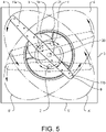
- Figure 5 shows in a top view an indication on how the sprayer arrangement 10 moves during operation in the washing chamber of figure 1 .
- the sprayer element 11 and the first gearing member 14 starts to rotate in an anti-clockwise direction.
- the teeth 15 and 21b interact resulting in that the first gearing element (and the centre of rotation of the sprayer element 11) moves in a circular path in a clockwise direction.
- This rotation and this revolving movement are indicated by arrows in figure 5 .
- the direction of rotation and movement can of course be reversed by directing the drive nozzles in the opposite direction.
- position X solid line for the sprayer element 11
- positions Y and Z dashed lines for the sprayer element 11
- Semi-dotted line A' shows the position of an endpoint A of one of the spray arms 11a during one full revolution of the first gearing element 14.
- a corresponding semi-dotted line B' is shown for an opposite end point B on the other spray arm 11b.
- each spray arm 11a, 11b in the horizontal plane forms an ellipse that extends between opposite corners 6 of the washing chamber.
- the two spray arms 11a, 11b form an X-shaped coverage area formed by the two crossing elliptical shapes. It can be seen from figure 5 that the (end parts A and B of the) sprayer element 11 comes closer to the corners 6 than if the sprayer element 11 would have been stationary and rotatable only around the central axis 20 in line with a conventional arrangement.
- the coverage areas are illustrated in figure 6 where i) circular area 100 is the horizontal area covered if the sprayer element 11 would have been stationary and rotatable only around the central axis 20 (conventional arrangement), ii) double-elliptic area 101 is the area covered by the sprayer arrangement 10 shown in figures 1-4 , and iii) area 102 is the horizontal area of the washing space not covered at all.
- the actual spray area may differ from what is shown in figures 5 and 6 since the nozzles 13 can be directed to form a spray area that differs from what is shown in figure 6 , at least at some vertical distance from the spray element 11.
- the source of the spraying i.e.
- the sprayer arrangement 10 allows the spray arms 11a, 11b to come closer to the corners than a conventional arrangement and thus makes it possible to come closer to the corner with the nozzles and provide for a better spraying in the corners.
- the exact design and positioning of the nozzles can vary depending on the application.
- Figure 7 shows a first alternative sprayer element 11' having opposite first and second spray arms 11a, 11b, a central region/inlet/axis of rotation 12 and nozzles 13 similar to what has been described above.
- the first alternative sprayer element 11' comprises a third spray arm 11c that extends radially from the central region 12 in a direction perpendicular to the first and second spray arms 11a, 11b.
- the third spray arm 11c is shorter than the first and second spray arms 11a, 11b to avoid hitting the side plates 5 of the washing space.
- the additional spray arm 11c increases the evenness of the spraying distribution in the horizontal plane.
- Figure 8 shows a second alternative sprayer element 11" having first, second and third spray arms 11a, 11b, 11c, a central region/axis of rotation 12 and nozzles 13 similar to what has been described in relation to figure 7 .
- the second alternative sprayer element 11" further comprises a fourth spray arm 11d that extends radially from the central region 12 in a direction perpendicular to the third spray arm 11c.
- the fourth spray arm 11d further increases the evenness of the spraying distribution in the horizontal plane.
- Sprayer elements with other structures are also possible to use.
- the dishwasher 4 is preferably provided with a controllable pump or other means for controlling the pressure of the fluid fed to the sprayer element 11, 31, 41. This way the rotational speed of the sprayer element 11, 31, 41 and thereby the revolving speed of the first gearing element 14 can be controlled and adapted to different operation modes of the dishwasher 4.
- the sprayer element may be clearly asymmetric with only one (long) spray arm extending from the axis of rotation.
Landscapes
- Washing And Drying Of Tableware (AREA)
Applications Claiming Priority (1)
| Application Number | Priority Date | Filing Date | Title |
|---|---|---|---|
| SE1750606A SE542159C2 (en) | 2017-05-16 | 2017-05-16 | Sprayer arrangement for a dishwasher |
Publications (2)
| Publication Number | Publication Date |
|---|---|
| EP3403564A1 EP3403564A1 (en) | 2018-11-21 |
| EP3403564B1 true EP3403564B1 (en) | 2022-08-24 |
Family
ID=62142962
Family Applications (1)
| Application Number | Title | Priority Date | Filing Date |
|---|---|---|---|
| EP18171154.0A Active EP3403564B1 (en) | 2017-05-16 | 2018-05-08 | Sprayer arrangement for a dishwasher |
Country Status (3)
| Country | Link |
|---|---|
| EP (1) | EP3403564B1 (pl) |
| PL (1) | PL3403564T3 (pl) |
| SE (1) | SE542159C2 (pl) |
Cited By (1)
| Publication number | Priority date | Publication date | Assignee | Title |
|---|---|---|---|---|
| EP4703046A1 (en) * | 2024-08-28 | 2026-03-04 | Teijo Pesukoneet Oy | Arrangement for spraying fluid, cleaning machine and method |
Families Citing this family (7)
| Publication number | Priority date | Publication date | Assignee | Title |
|---|---|---|---|---|
| CN110419999B (zh) * | 2019-07-25 | 2024-06-07 | 广东广美工贸有限公司 | 一种喷水座自转及公转的喷臂 |
| EP4186407B1 (en) | 2021-11-25 | 2024-05-29 | HAIER Germany GmbH | Liquid sprayer for a dishwasher and dishwasher |
| CN115607081B (zh) * | 2022-09-13 | 2025-10-21 | 华帝股份有限公司 | 一种喷臂装置及其洗碗机 |
| CN115429184A (zh) * | 2022-10-08 | 2022-12-06 | 华帝股份有限公司 | 喷臂组件和洗碗机 |
| EP4611941A1 (en) * | 2022-10-31 | 2025-09-10 | Johnson Screens, Inc. | Asymmetrical rotating spray nozzle assembly for filtration screen |
| CN117018236B (zh) * | 2023-05-29 | 2025-09-09 | 宁波方太厨具有限公司 | 一种消毒柜 |
| CN116440680B (zh) * | 2023-06-01 | 2026-04-07 | 福建凯美特气体有限公司 | 一种二氧化碳生产用吸附塔 |
Family Cites Families (4)
| Publication number | Priority date | Publication date | Assignee | Title |
|---|---|---|---|---|
| US5579789A (en) * | 1995-01-04 | 1996-12-03 | Whirlpool Corporation | Food soil handling system for a dishwasher |
| JP2005329022A (ja) | 2004-05-20 | 2005-12-02 | Toshiba Tec Corp | 洗浄機 |
| EP1882435A1 (en) * | 2006-07-24 | 2008-01-30 | Electrolux Home Products Corporation N.V. | Revolving sprinkling assembly |
| EP2898810A1 (en) * | 2014-01-28 | 2015-07-29 | Bonferraro S.p.A. | Revolving sprinkling assembly for dishwasher |
-
2017
- 2017-05-16 SE SE1750606A patent/SE542159C2/en unknown
-
2018
- 2018-05-08 EP EP18171154.0A patent/EP3403564B1/en active Active
- 2018-05-08 PL PL18171154.0T patent/PL3403564T3/pl unknown
Cited By (1)
| Publication number | Priority date | Publication date | Assignee | Title |
|---|---|---|---|---|
| EP4703046A1 (en) * | 2024-08-28 | 2026-03-04 | Teijo Pesukoneet Oy | Arrangement for spraying fluid, cleaning machine and method |
Also Published As
| Publication number | Publication date |
|---|---|
| PL3403564T3 (pl) | 2023-01-30 |
| SE1750606A1 (en) | 2018-11-17 |
| SE542159C2 (en) | 2020-03-03 |
| EP3403564A1 (en) | 2018-11-21 |
Similar Documents
| Publication | Publication Date | Title |
|---|---|---|
| EP3403564B1 (en) | Sprayer arrangement for a dishwasher | |
| CN112654279B (zh) | 具有可旋转分流阀的洗碗机 | |
| US8905053B2 (en) | Variable speed and multi-angle nozzle spray arm assembly for a dishwasher | |
| CN104814710B (zh) | 喷臂组件以及具有其的洗碗机 | |
| US9980624B2 (en) | Variable position diverter for an appliance | |
| US9743822B2 (en) | Variable position diverter for an appliance | |
| CN112672669B (zh) | 具有用于升降架的对接装置的洗碗机 | |
| US11434600B2 (en) | Laundry treating appliance door assembly comprising a plastic fishbowl | |
| US20060278258A1 (en) | Dishwasher | |
| EP2772176B1 (en) | Dishwasher with hydraulically driven sprayer | |
| CN107028572B (zh) | 用于洗碗机的喷臂装置及具有其的洗碗机 | |
| CN107028573B (zh) | 用于洗碗机的喷臂装置及具有其的洗碗机 | |
| US11412912B2 (en) | Dishwasher with tubular spray element slip ring alignment | |
| CN204744064U (zh) | 喷臂组件以及具有其的洗碗机 | |
| KR102431199B1 (ko) | 식기세척기 | |
| CN209144502U (zh) | 波轮洗衣机及其喷淋系统和外桶盖 | |
| US20220022723A1 (en) | Space efficient flow controller for dishwasher | |
| CN206675493U (zh) | 用于洗碗机的喷臂装置及具有其的洗碗机 | |
| KR100850998B1 (ko) | 식기세척기의 운전방법 | |
| CN111297293B (zh) | 一种洗碗机喷淋装置及洗碗机 | |
| EP3618680B1 (en) | A dishwasher comprising a water spray nozzle | |
| WO2020125998A1 (en) | Sealed flow controller for dishwasher | |
| KR102311407B1 (ko) | 식기세척기용 로터 조립체 | |
| US11910981B2 (en) | Flow controller for dishwasher | |
| CN206621339U (zh) | 用于洗碗机的喷臂装置及具有其的洗碗机 |
Legal Events
| Date | Code | Title | Description |
|---|---|---|---|
| PUAI | Public reference made under article 153(3) epc to a published international application that has entered the european phase |
Free format text: ORIGINAL CODE: 0009012 |
|
| STAA | Information on the status of an ep patent application or granted ep patent |
Free format text: STATUS: THE APPLICATION HAS BEEN PUBLISHED |
|
| AK | Designated contracting states |
Kind code of ref document: A1 Designated state(s): AL AT BE BG CH CY CZ DE DK EE ES FI FR GB GR HR HU IE IS IT LI LT LU LV MC MK MT NL NO PL PT RO RS SE SI SK SM TR |
|
| AX | Request for extension of the european patent |
Extension state: BA ME |
|
| RIN1 | Information on inventor provided before grant (corrected) |
Inventor name: QVICK, AXEL Inventor name: RAUCH, MICHAEL Inventor name: LARSSON, JENNY Inventor name: WERNER, AXEL Inventor name: JOHANSSON, SAMUEL |
|
| STAA | Information on the status of an ep patent application or granted ep patent |
Free format text: STATUS: REQUEST FOR EXAMINATION WAS MADE |
|
| 17P | Request for examination filed |
Effective date: 20190521 |
|
| RBV | Designated contracting states (corrected) |
Designated state(s): AL AT BE BG CH CY CZ DE DK EE ES FI FR GB GR HR HU IE IS IT LI LT LU LV MC MK MT NL NO PL PT RO RS SE SI SK SM TR |
|
| GRAP | Despatch of communication of intention to grant a patent |
Free format text: ORIGINAL CODE: EPIDOSNIGR1 |
|
| STAA | Information on the status of an ep patent application or granted ep patent |
Free format text: STATUS: GRANT OF PATENT IS INTENDED |
|
| INTG | Intention to grant announced |
Effective date: 20220325 |
|
| GRAS | Grant fee paid |
Free format text: ORIGINAL CODE: EPIDOSNIGR3 |
|
| GRAA | (expected) grant |
Free format text: ORIGINAL CODE: 0009210 |
|
| STAA | Information on the status of an ep patent application or granted ep patent |
Free format text: STATUS: THE PATENT HAS BEEN GRANTED |
|
| AK | Designated contracting states |
Kind code of ref document: B1 Designated state(s): AL AT BE BG CH CY CZ DE DK EE ES FI FR GB GR HR HU IE IS IT LI LT LU LV MC MK MT NL NO PL PT RO RS SE SI SK SM TR |
|
| REG | Reference to a national code |
Ref country code: CH Ref legal event code: EP |
|
| REG | Reference to a national code |
Ref country code: DE Ref legal event code: R096 Ref document number: 602018039599 Country of ref document: DE |
|
| REG | Reference to a national code |
Ref country code: IE Ref legal event code: FG4D |
|
| REG | Reference to a national code |
Ref country code: AT Ref legal event code: REF Ref document number: 1513098 Country of ref document: AT Kind code of ref document: T Effective date: 20220915 |
|
| REG | Reference to a national code |
Ref country code: LT Ref legal event code: MG9D |
|
| REG | Reference to a national code |
Ref country code: NL Ref legal event code: MP Effective date: 20220824 |
|
| PG25 | Lapsed in a contracting state [announced via postgrant information from national office to epo] |
Ref country code: SE Free format text: LAPSE BECAUSE OF FAILURE TO SUBMIT A TRANSLATION OF THE DESCRIPTION OR TO PAY THE FEE WITHIN THE PRESCRIBED TIME-LIMIT Effective date: 20220824 Ref country code: RS Free format text: LAPSE BECAUSE OF FAILURE TO SUBMIT A TRANSLATION OF THE DESCRIPTION OR TO PAY THE FEE WITHIN THE PRESCRIBED TIME-LIMIT Effective date: 20220824 Ref country code: PT Free format text: LAPSE BECAUSE OF FAILURE TO SUBMIT A TRANSLATION OF THE DESCRIPTION OR TO PAY THE FEE WITHIN THE PRESCRIBED TIME-LIMIT Effective date: 20221226 Ref country code: NO Free format text: LAPSE BECAUSE OF FAILURE TO SUBMIT A TRANSLATION OF THE DESCRIPTION OR TO PAY THE FEE WITHIN THE PRESCRIBED TIME-LIMIT Effective date: 20221124 Ref country code: NL Free format text: LAPSE BECAUSE OF FAILURE TO SUBMIT A TRANSLATION OF THE DESCRIPTION OR TO PAY THE FEE WITHIN THE PRESCRIBED TIME-LIMIT Effective date: 20220824 Ref country code: LV Free format text: LAPSE BECAUSE OF FAILURE TO SUBMIT A TRANSLATION OF THE DESCRIPTION OR TO PAY THE FEE WITHIN THE PRESCRIBED TIME-LIMIT Effective date: 20220824 Ref country code: LT Free format text: LAPSE BECAUSE OF FAILURE TO SUBMIT A TRANSLATION OF THE DESCRIPTION OR TO PAY THE FEE WITHIN THE PRESCRIBED TIME-LIMIT Effective date: 20220824 Ref country code: FI Free format text: LAPSE BECAUSE OF FAILURE TO SUBMIT A TRANSLATION OF THE DESCRIPTION OR TO PAY THE FEE WITHIN THE PRESCRIBED TIME-LIMIT Effective date: 20220824 |
|
| REG | Reference to a national code |
Ref country code: AT Ref legal event code: MK05 Ref document number: 1513098 Country of ref document: AT Kind code of ref document: T Effective date: 20220824 |
|
| PG25 | Lapsed in a contracting state [announced via postgrant information from national office to epo] |
Ref country code: IS Free format text: LAPSE BECAUSE OF FAILURE TO SUBMIT A TRANSLATION OF THE DESCRIPTION OR TO PAY THE FEE WITHIN THE PRESCRIBED TIME-LIMIT Effective date: 20221224 Ref country code: HR Free format text: LAPSE BECAUSE OF FAILURE TO SUBMIT A TRANSLATION OF THE DESCRIPTION OR TO PAY THE FEE WITHIN THE PRESCRIBED TIME-LIMIT Effective date: 20220824 Ref country code: GR Free format text: LAPSE BECAUSE OF FAILURE TO SUBMIT A TRANSLATION OF THE DESCRIPTION OR TO PAY THE FEE WITHIN THE PRESCRIBED TIME-LIMIT Effective date: 20221125 |
|
| PG25 | Lapsed in a contracting state [announced via postgrant information from national office to epo] |
Ref country code: SM Free format text: LAPSE BECAUSE OF FAILURE TO SUBMIT A TRANSLATION OF THE DESCRIPTION OR TO PAY THE FEE WITHIN THE PRESCRIBED TIME-LIMIT Effective date: 20220824 Ref country code: RO Free format text: LAPSE BECAUSE OF FAILURE TO SUBMIT A TRANSLATION OF THE DESCRIPTION OR TO PAY THE FEE WITHIN THE PRESCRIBED TIME-LIMIT Effective date: 20220824 Ref country code: ES Free format text: LAPSE BECAUSE OF FAILURE TO SUBMIT A TRANSLATION OF THE DESCRIPTION OR TO PAY THE FEE WITHIN THE PRESCRIBED TIME-LIMIT Effective date: 20220824 Ref country code: DK Free format text: LAPSE BECAUSE OF FAILURE TO SUBMIT A TRANSLATION OF THE DESCRIPTION OR TO PAY THE FEE WITHIN THE PRESCRIBED TIME-LIMIT Effective date: 20220824 Ref country code: CZ Free format text: LAPSE BECAUSE OF FAILURE TO SUBMIT A TRANSLATION OF THE DESCRIPTION OR TO PAY THE FEE WITHIN THE PRESCRIBED TIME-LIMIT Effective date: 20220824 Ref country code: AT Free format text: LAPSE BECAUSE OF FAILURE TO SUBMIT A TRANSLATION OF THE DESCRIPTION OR TO PAY THE FEE WITHIN THE PRESCRIBED TIME-LIMIT Effective date: 20220824 |
|
| REG | Reference to a national code |
Ref country code: DE Ref legal event code: R097 Ref document number: 602018039599 Country of ref document: DE |
|
| PG25 | Lapsed in a contracting state [announced via postgrant information from national office to epo] |
Ref country code: SK Free format text: LAPSE BECAUSE OF FAILURE TO SUBMIT A TRANSLATION OF THE DESCRIPTION OR TO PAY THE FEE WITHIN THE PRESCRIBED TIME-LIMIT Effective date: 20220824 Ref country code: EE Free format text: LAPSE BECAUSE OF FAILURE TO SUBMIT A TRANSLATION OF THE DESCRIPTION OR TO PAY THE FEE WITHIN THE PRESCRIBED TIME-LIMIT Effective date: 20220824 |
|
| PG25 | Lapsed in a contracting state [announced via postgrant information from national office to epo] |
Ref country code: AL Free format text: LAPSE BECAUSE OF FAILURE TO SUBMIT A TRANSLATION OF THE DESCRIPTION OR TO PAY THE FEE WITHIN THE PRESCRIBED TIME-LIMIT Effective date: 20220824 |
|
| PLBE | No opposition filed within time limit |
Free format text: ORIGINAL CODE: 0009261 |
|
| STAA | Information on the status of an ep patent application or granted ep patent |
Free format text: STATUS: NO OPPOSITION FILED WITHIN TIME LIMIT |
|
| 26N | No opposition filed |
Effective date: 20230525 |
|
| PG25 | Lapsed in a contracting state [announced via postgrant information from national office to epo] |
Ref country code: SI Free format text: LAPSE BECAUSE OF FAILURE TO SUBMIT A TRANSLATION OF THE DESCRIPTION OR TO PAY THE FEE WITHIN THE PRESCRIBED TIME-LIMIT Effective date: 20220824 |
|
| REG | Reference to a national code |
Ref country code: CH Ref legal event code: PL |
|
| PG25 | Lapsed in a contracting state [announced via postgrant information from national office to epo] |
Ref country code: MC Free format text: LAPSE BECAUSE OF FAILURE TO SUBMIT A TRANSLATION OF THE DESCRIPTION OR TO PAY THE FEE WITHIN THE PRESCRIBED TIME-LIMIT Effective date: 20220824 |
|
| GBPC | Gb: european patent ceased through non-payment of renewal fee |
Effective date: 20230508 |
|
| REG | Reference to a national code |
Ref country code: BE Ref legal event code: MM Effective date: 20230531 |
|
| PG25 | Lapsed in a contracting state [announced via postgrant information from national office to epo] |
Ref country code: MC Free format text: LAPSE BECAUSE OF FAILURE TO SUBMIT A TRANSLATION OF THE DESCRIPTION OR TO PAY THE FEE WITHIN THE PRESCRIBED TIME-LIMIT Effective date: 20220824 Ref country code: LU Free format text: LAPSE BECAUSE OF NON-PAYMENT OF DUE FEES Effective date: 20230508 Ref country code: LI Free format text: LAPSE BECAUSE OF NON-PAYMENT OF DUE FEES Effective date: 20230531 Ref country code: CH Free format text: LAPSE BECAUSE OF NON-PAYMENT OF DUE FEES Effective date: 20230531 |
|
| REG | Reference to a national code |
Ref country code: IE Ref legal event code: MM4A |
|
| PG25 | Lapsed in a contracting state [announced via postgrant information from national office to epo] |
Ref country code: IE Free format text: LAPSE BECAUSE OF NON-PAYMENT OF DUE FEES Effective date: 20230508 |
|
| PG25 | Lapsed in a contracting state [announced via postgrant information from national office to epo] |
Ref country code: IE Free format text: LAPSE BECAUSE OF NON-PAYMENT OF DUE FEES Effective date: 20230508 Ref country code: GB Free format text: LAPSE BECAUSE OF NON-PAYMENT OF DUE FEES Effective date: 20230508 |
|
| PG25 | Lapsed in a contracting state [announced via postgrant information from national office to epo] |
Ref country code: BE Free format text: LAPSE BECAUSE OF NON-PAYMENT OF DUE FEES Effective date: 20230531 Ref country code: FR Free format text: LAPSE BECAUSE OF NON-PAYMENT OF DUE FEES Effective date: 20230531 |
|
| PG25 | Lapsed in a contracting state [announced via postgrant information from national office to epo] |
Ref country code: BG Free format text: LAPSE BECAUSE OF FAILURE TO SUBMIT A TRANSLATION OF THE DESCRIPTION OR TO PAY THE FEE WITHIN THE PRESCRIBED TIME-LIMIT Effective date: 20220824 |
|
| PG25 | Lapsed in a contracting state [announced via postgrant information from national office to epo] |
Ref country code: BG Free format text: LAPSE BECAUSE OF FAILURE TO SUBMIT A TRANSLATION OF THE DESCRIPTION OR TO PAY THE FEE WITHIN THE PRESCRIBED TIME-LIMIT Effective date: 20220824 |
|
| PGFP | Annual fee paid to national office [announced via postgrant information from national office to epo] |
Ref country code: DE Payment date: 20250528 Year of fee payment: 8 Ref country code: PL Payment date: 20250408 Year of fee payment: 8 |
|
| PGFP | Annual fee paid to national office [announced via postgrant information from national office to epo] |
Ref country code: IT Payment date: 20250512 Year of fee payment: 8 |
|
| PG25 | Lapsed in a contracting state [announced via postgrant information from national office to epo] |
Ref country code: CY Free format text: LAPSE BECAUSE OF FAILURE TO SUBMIT A TRANSLATION OF THE DESCRIPTION OR TO PAY THE FEE WITHIN THE PRESCRIBED TIME-LIMIT; INVALID AB INITIO Effective date: 20180508 |
|
| PGFP | Annual fee paid to national office [announced via postgrant information from national office to epo] |
Ref country code: TR Payment date: 20250409 Year of fee payment: 8 |
|
| PG25 | Lapsed in a contracting state [announced via postgrant information from national office to epo] |
Ref country code: HU Free format text: LAPSE BECAUSE OF FAILURE TO SUBMIT A TRANSLATION OF THE DESCRIPTION OR TO PAY THE FEE WITHIN THE PRESCRIBED TIME-LIMIT; INVALID AB INITIO Effective date: 20180508 |