EP3403571B1 - Utilisation de capteurs de localisation proximale pour améliorer la précision et l'immunité aux interférences de localisation - Google Patents
Utilisation de capteurs de localisation proximale pour améliorer la précision et l'immunité aux interférences de localisation Download PDFInfo
- Publication number
- EP3403571B1 EP3403571B1 EP18173228.0A EP18173228A EP3403571B1 EP 3403571 B1 EP3403571 B1 EP 3403571B1 EP 18173228 A EP18173228 A EP 18173228A EP 3403571 B1 EP3403571 B1 EP 3403571B1
- Authority
- EP
- European Patent Office
- Prior art keywords
- tool
- magnetic field
- location
- field data
- convergence
- Prior art date
- Legal status (The legal status is an assumption and is not a legal conclusion. Google has not performed a legal analysis and makes no representation as to the accuracy of the status listed.)
- Active
Links
Images


Classifications
-
- A—HUMAN NECESSITIES
- A61—MEDICAL OR VETERINARY SCIENCE; HYGIENE
- A61B—DIAGNOSIS; SURGERY; IDENTIFICATION
- A61B34/00—Computer-aided surgery; Manipulators or robots specially adapted for use in surgery
- A61B34/20—Surgical navigation systems; Devices for tracking or guiding surgical instruments, e.g. for frameless stereotaxis
-
- G—PHYSICS
- G01—MEASURING; TESTING
- G01S—RADIO DIRECTION-FINDING; RADIO NAVIGATION; DETERMINING DISTANCE OR VELOCITY BY USE OF RADIO WAVES; LOCATING OR PRESENCE-DETECTING BY USE OF THE REFLECTION OR RERADIATION OF RADIO WAVES; ANALOGOUS ARRANGEMENTS USING OTHER WAVES
- G01S17/00—Systems using the reflection or reradiation of electromagnetic waves other than radio waves, e.g. lidar systems
- G01S17/02—Systems using the reflection of electromagnetic waves other than radio waves
- G01S17/06—Systems determining position data of a target
-
- A—HUMAN NECESSITIES
- A61—MEDICAL OR VETERINARY SCIENCE; HYGIENE
- A61B—DIAGNOSIS; SURGERY; IDENTIFICATION
- A61B5/00—Measuring for diagnostic purposes; Identification of persons
- A61B5/06—Devices, other than using radiation, for detecting or locating foreign bodies ; Determining position of diagnostic devices within or on the body of the patient
- A61B5/061—Determining position of a probe within the body employing means separate from the probe, e.g. sensing internal probe position employing impedance electrodes on the surface of the body
- A61B5/062—Determining position of a probe within the body employing means separate from the probe, e.g. sensing internal probe position employing impedance electrodes on the surface of the body using magnetic field
-
- A—HUMAN NECESSITIES
- A61—MEDICAL OR VETERINARY SCIENCE; HYGIENE
- A61B—DIAGNOSIS; SURGERY; IDENTIFICATION
- A61B5/00—Measuring for diagnostic purposes; Identification of persons
- A61B5/145—Measuring characteristics of blood in vivo, e.g. gas concentration or pH-value ; Measuring characteristics of body fluids or tissues, e.g. interstitial fluid or cerebral tissue
- A61B5/1495—Calibrating or testing of in-vivo probes
-
- A—HUMAN NECESSITIES
- A61—MEDICAL OR VETERINARY SCIENCE; HYGIENE
- A61B—DIAGNOSIS; SURGERY; IDENTIFICATION
- A61B5/00—Measuring for diagnostic purposes; Identification of persons
- A61B5/68—Arrangements of detecting, measuring or recording means, e.g. sensors, in relation to patient
- A61B5/6846—Arrangements of detecting, measuring or recording means, e.g. sensors, in relation to patient specially adapted to be brought in contact with an internal body part, i.e. invasive
- A61B5/6847—Arrangements of detecting, measuring or recording means, e.g. sensors, in relation to patient specially adapted to be brought in contact with an internal body part, i.e. invasive mounted on an invasive device
- A61B5/6852—Catheters
-
- A—HUMAN NECESSITIES
- A61—MEDICAL OR VETERINARY SCIENCE; HYGIENE
- A61B—DIAGNOSIS; SURGERY; IDENTIFICATION
- A61B5/00—Measuring for diagnostic purposes; Identification of persons
- A61B5/74—Details of notification to user or communication with user or patient; User input means
- A61B5/742—Details of notification to user or communication with user or patient; User input means using visual displays
-
- G—PHYSICS
- G01—MEASURING; TESTING
- G01S—RADIO DIRECTION-FINDING; RADIO NAVIGATION; DETERMINING DISTANCE OR VELOCITY BY USE OF RADIO WAVES; LOCATING OR PRESENCE-DETECTING BY USE OF THE REFLECTION OR RERADIATION OF RADIO WAVES; ANALOGOUS ARRANGEMENTS USING OTHER WAVES
- G01S17/00—Systems using the reflection or reradiation of electromagnetic waves other than radio waves, e.g. lidar systems
- G01S17/02—Systems using the reflection of electromagnetic waves other than radio waves
- G01S17/06—Systems determining position data of a target
- G01S17/42—Simultaneous measurement of distance and other co-ordinates
-
- G—PHYSICS
- G01—MEASURING; TESTING
- G01S—RADIO DIRECTION-FINDING; RADIO NAVIGATION; DETERMINING DISTANCE OR VELOCITY BY USE OF RADIO WAVES; LOCATING OR PRESENCE-DETECTING BY USE OF THE REFLECTION OR RERADIATION OF RADIO WAVES; ANALOGOUS ARRANGEMENTS USING OTHER WAVES
- G01S17/00—Systems using the reflection or reradiation of electromagnetic waves other than radio waves, e.g. lidar systems
- G01S17/88—Lidar systems specially adapted for specific applications
- G01S17/89—Lidar systems specially adapted for specific applications for mapping or imaging
-
- G—PHYSICS
- G01—MEASURING; TESTING
- G01S—RADIO DIRECTION-FINDING; RADIO NAVIGATION; DETERMINING DISTANCE OR VELOCITY BY USE OF RADIO WAVES; LOCATING OR PRESENCE-DETECTING BY USE OF THE REFLECTION OR RERADIATION OF RADIO WAVES; ANALOGOUS ARRANGEMENTS USING OTHER WAVES
- G01S7/00—Details of systems according to groups G01S13/00, G01S15/00, G01S17/00
- G01S7/48—Details of systems according to groups G01S13/00, G01S15/00, G01S17/00 of systems according to group G01S17/00
- G01S7/497—Means for monitoring or calibrating
-
- A—HUMAN NECESSITIES
- A61—MEDICAL OR VETERINARY SCIENCE; HYGIENE
- A61B—DIAGNOSIS; SURGERY; IDENTIFICATION
- A61B34/00—Computer-aided surgery; Manipulators or robots specially adapted for use in surgery
- A61B34/20—Surgical navigation systems; Devices for tracking or guiding surgical instruments, e.g. for frameless stereotaxis
- A61B2034/2046—Tracking techniques
- A61B2034/2051—Electromagnetic tracking systems
-
- A—HUMAN NECESSITIES
- A61—MEDICAL OR VETERINARY SCIENCE; HYGIENE
- A61B—DIAGNOSIS; SURGERY; IDENTIFICATION
- A61B2562/00—Details of sensors; Constructional details of sensor housings or probes; Accessories for sensors
- A61B2562/04—Arrangements of multiple sensors of the same type
- A61B2562/043—Arrangements of multiple sensors of the same type in a linear array
-
- G—PHYSICS
- G01—MEASURING; TESTING
- G01S—RADIO DIRECTION-FINDING; RADIO NAVIGATION; DETERMINING DISTANCE OR VELOCITY BY USE OF RADIO WAVES; LOCATING OR PRESENCE-DETECTING BY USE OF THE REFLECTION OR RERADIATION OF RADIO WAVES; ANALOGOUS ARRANGEMENTS USING OTHER WAVES
- G01S7/00—Details of systems according to groups G01S13/00, G01S15/00, G01S17/00
- G01S7/48—Details of systems according to groups G01S13/00, G01S15/00, G01S17/00 of systems according to group G01S17/00
- G01S7/481—Constructional features, e.g. arrangements of optical elements
- G01S7/4817—Constructional features, e.g. arrangements of optical elements relating to scanning
Definitions
- EP 1174082 A1 discloses a system for determining the position of a medical device having a sensor (26), which comprises a plurality of field radiators wherein each field radiator has a plurality of radiator elements. Each radiator element generates a magnetic field such that each magnetic field is distinct from one another due to the use of a different frequency. The magnetic fields are measured by the sensor.
- the field radiators and the sensor are connected to a signal processor.
- the signal processor includes an initial position estimator for establishing an initial position estimate for the sensor; a magnetic field calculator for calculating the magnetic field at the initial position estimate; a steepest descent calculator for calculating a steepest descent of the calculated magnetic field to the measured magnetic field; and a new position estimate calculator for calculating a new position estimate of said sensor based on said steepest descent.
- the signal processor determines the position of the sensor when the new position estimate of the sensor is within the desired range of accuracy for the system.
- Alternative field radiator arrangements are also provided in conjunction with an algorithm utilizing a global convergent technique.
- EP 1181891 A2 discloses a device to detect the location of a magnet coupled to an indwelling medical device within a patient, which uses three or more sets of magnetic sensors each having sensor elements arranged in a known fashion. Each sensor element senses the magnetic field strength generated by the magnet and provides data indicative of the direction of the magnet in a three-dimensional space.
- the device uses fundamental equations for electricity and magnetism that relate measured magnetic field strength and magnetic field gradient to the location and strength of a magnetic dipole.
- the device uses an iterative process to determine the actual location and orientation of the magnet. An initial estimate of the location and orientation of the magnet results in the generation of predicted magnetic field values. The predicted magnetic field values are compared with the actual measured values provided by the magnetic sensors.
- the device Based on the difference between the predicted values and the measured values, the device estimates a new location of the magnet and calculates new predicted magnetic field strength values. The iteration process continues until the predicted values match the measured values within a desired degree of tolerance. At that point, the estimated location matches the actual location within a predetermined degree of tolerance.
- a two-dimensional display provides an indication of the location of the magnet with respect to the housing of the detector.
- EP1502544 (A1)discloses an invasive probe tip comprising multiple coil sensors.
- a convergence algorithm is used, however it fails to disclose the step-wise, iterative convergence algorithm as claimed (ie, first use one single sensor, and if convergence fails in that case, then use signal from further sensors for a further convergence step).
- a system and a method for determining the location of a tool are provided.
- a computer program product as claimed hereinafter is also provided.
- Magnetic navigation systems used for navigating tools generally comprise coils with magnetic fields, and each coil has its own frequency.
- the systems include one or more sensors in space, each sensor typically receiving all coil frequencies. Since each coil has a unique frequency with respect to other coils, the sensor can tell which coil is where.
- Magnetic systems are typically quite accurate for the navigation of a particular tool, but the systems are very susceptible to interference from other magnetic elements and/or devices. For example, if a second magnetic tool is activated or used, different from the particular (first) tool being navigated by the system, interference is generated by this second tool.
- magnetic navigation system can be found in CARTO TM , produced by Biosense Webster, Inc. (Diamond Bar, California).
- magnetic fields are typically generated by a location pad consisting of field generators.
- magnetic position sensing may be used to determine position coordinates of distal end of a tool inside a patient's organ.
- a driver circuit in a console or a location pad drives field generators to generate magnetic fields within the body of patient.
- the field generators comprise coils, which are placed beneath the patient's body at known positions external to the patient. These coils generate magnetic fields in a predefined working volume that contains the patient's organ to be explored.
- a magnetic field sensor within distal end of the tool generates electrical signals in response to these magnetic fields.
- a signal processor processes these signals in order to determine the position coordinates of the distal end, typically including both location and orientation coordinates.
- This method of position sensing is implemented in the above-mentioned CARTO TM system and is described in detail in U.S. Pat. Nos. 5,391,199 , 6,690,963 , 6,484,118 , 6,239,724 , 6,618,612 and 6,332,089 , in PCT Patent Publication WO 96/05768 , and in U.S. Patent Application Publications 2002/0065455 A1 , 2003/0120150 A1 and 2004/0068178 A1 .
- the location of the catheter's distal sensor is typically determined by measuring the main magnetic field enabled in the navigation system. These magnetic field measurements are typically sensed by the distal sensor of the particular tool, convergence is performed on the sensed measurements and the location, e.g., position and orientation, of the tool is determined since the tool is rigid and the location of the distal sensor relative to the tool is known.
- magnetic fields are typically generated by a location pad consisting of field generators. Each field generator emits a field in a specific frequency. In one embodiment, a location field generated by the field generators of the location pad emits fifteen (15) frequencies.
- two or more additional, proximal sensors can be placed on the tool, e.g., a catheter tube; these sensors, in addition to the distal sensor, can measure the strength of the main magnetic field.
- one or more of the additional, proximal sensors can be used to determine the tool's location to enable more accurate navigation. In particular, whether the proximal sensors converge better than the distal sensor can be checked. If the proximal sensors converge better, this indicates that the distal sensor suffers from magnetic disturbance (otherwise it would perfectly converge). As discussed below, convergence is a "grade" or numerical value that can be compared to a threshold, for example, to determine how close one converges to the theoretical field.
- the inventive system comprises multiple sensors on a tool and is able to test convergence and switch to a sensor that is not subject to interference.
- convergence is tested as calculation of root means square error (RMSE) of the value of received fields minus the value of those fields that are assumed, based on calibration, to be in the specific point or location.
- RMSE root means square error
- the catheter hub 18 comprises a WiFi antenna 24 and an RF Sync Rx antenna 28, for receiving signals from the tools that are navigated.
- the LP driver 20 comprises a WiFi antenna 24 and an RF Sync Tx antenna 26 enabling the LP driver 20 to transmit current to the location pad 30.
- the position and orientation of the distal end of the tool 10 may be ascertained by determining the position of the magnetic field locating sensor 32, 34, 36.
- the tool 10 may be locatable with a non-ionizing field, such as an electromagnetic or acoustic field.
- the tip of the tool 10 may comprise a transmitting or receiving antenna (not shown) for the relevant field.
- Receiving or transmitting antennas (not shown) for the non-ionizing field are attached to a patient to be examined.
- a receiver or transmitter is connected to these antennas, and converts the received field waves into electrical locating or image signals.
- the location pad 30 may comprise coils (not shown), which are one type of magnetic transducer that may be used in embodiments of the present invention.
- coils as magnetic transducers, other types of magnetic transducers may be used in alternative embodiments, as will be apparent to those skilled in the art.
- FIG. 2 is sectional view of the distal end of a tool 10, in accordance with an embodiment of the present invention.
- the tool 10 has multiple sensors 32, 34, 36 (while three sensors are shown, more or fewer than three sensors can be used).
- Each sensor can receive signals from coils in the location pad 30.
- One or more of the coils may also be used to output signals in response to the magnetic fields generated by field generators, typically located in the location pad 30, and thus serve as position sensing coils.
- Processor 14 processes these signals in order to determine the coordinates (position and orientation) of the distal end of the tool 10 in the external frame of reference that is defined by the field generators.
- processor 14 receives the signal data generated by the sensors 32, 34, 36 on the tool 10 via the catheter hub 18. Processor 14 processes these signal data in order to determine the location of the tool 10.
- the processing can include analysis of calculating convergence, as mentioned above.
- convergence can be found when the difference between the calibrated magnetic field at a particular location and the actual magnetic field (e.g., in Gauss/Ampere) at the same location is less than a predetermined threshold.
- ⁇ Threshold may be used to determine convergence.
- the result of the convergence calculation is the calculated location of the distal end of the tool 10.
- the present invention may be applied in applications that require accurate locating of a tool within a body, and particularly in therapeutic and diagnostic applications that use invasive probes, both in the heart and in other organs of the body.
- the devices and techniques for position and pressure sensing that are implemented in the inventive system may be applied in guiding and controlling the use of a catheter insertion sheath. If the position of the sheath is not properly controlled and excessive force is used in its insertion, the sheath may perforate the heart wall or vascular tissue. This eventuality can be avoided by sensing the position of and pressure on the distal tip of the sheath.
- distal tip as used herein should be understood to include any sort of structure at the distal end of a probe that may be bent and/or displaced relative to the main body of the probe.
- FIG. 3 is a schematic view of a tool 10 in the presence of a metal object, such as an external metal tool 38.
- a metal object such as an external metal tool 38.
- the interference caused by this object 38 is noticeable when it comes in close proximity to the distal end of the tool 10.
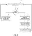
- data from proximal sensors 34 and 36 can be used to calculate convergence.
- data from sensor 32, the distal end sensor can be ignored.
- the result of the convergence calculation is the calculated location of the distal end of the tool 10. This calculation initially is performed with data from the distal end sensor 32; however, when interference is determined at the distal end sensor 32, the convergence calculation is performed with data from other sensors 34, 36 on the tool 10.
- step S4 obtain data from other sensors 34, 36 on tool 10.
- step S5 analyze data obtained from the other sensors 34, 36, and perform the convergence algorithm with data from the non-distal end (non-disturbed) sensors.
- step S6 calculate the location of the tool 10 using additional data from the non-distal end sensor(s).
- non-transitory computer-readable storage mediums include a ROM, a random access memory (RAM), a register, cache memory, semiconductor memory devices, magnetic media such as internal hard disks and removable disks, magnetooptical media, and optical media such as CD-ROM disks, and digital versatile disks (DVDs).
Landscapes
- Health & Medical Sciences (AREA)
- Life Sciences & Earth Sciences (AREA)
- Engineering & Computer Science (AREA)
- Physics & Mathematics (AREA)
- Surgery (AREA)
- Public Health (AREA)
- Veterinary Medicine (AREA)
- Heart & Thoracic Surgery (AREA)
- Medical Informatics (AREA)
- Molecular Biology (AREA)
- Animal Behavior & Ethology (AREA)
- General Health & Medical Sciences (AREA)
- Biomedical Technology (AREA)
- Pathology (AREA)
- Biophysics (AREA)
- Electromagnetism (AREA)
- Computer Networks & Wireless Communication (AREA)
- General Physics & Mathematics (AREA)
- Radar, Positioning & Navigation (AREA)
- Remote Sensing (AREA)
- Human Computer Interaction (AREA)
- Optics & Photonics (AREA)
- Nuclear Medicine, Radiotherapy & Molecular Imaging (AREA)
- Robotics (AREA)
- Media Introduction/Drainage Providing Device (AREA)
- Measurement Of Length, Angles, Or The Like Using Electric Or Magnetic Means (AREA)
Claims (7)
- Procédé permettant de déterminer l'emplacement d'un outil (10) en présence d'interférences métalliques, l'outil ayant un capteur d'extrémité distale (32) et au moins un autre capteur (34, 36), le procédé comprenant :l'obtention de données de champ magnétique à partir du capteur d'extrémité distale (32) de l'outil (10) ; avec un processeur (14), la réalisation d'une convergence sur les données de champ magnétique obtenues en calculant une différence entre les données obtenues et un champ magnétique réel au même emplacement, la convergence indiquant si les données de champ magnétique obtenues sont perturbées ou non en déterminant qu'une convergence est indiquée lorsque la différence est inférieure à un seuil prédéterminé ;lorsque la convergence indique que les données de champ magnétique obtenues ne sont pas perturbées, le calcul de l'emplacement de l'outil (10) à l'aide des données de champ magnétique obtenues ; etlorsque la convergence indique que les données de champ magnétique obtenues sont perturbées :l'obtention de données de champ magnétique supplémentaires à partir de l'au moins un autre capteur (34, 36) de l'outil (10) ;caractérisé en ce que le processeur est en outre configuré pour :effectuer la convergence sur les données de champ magnétique supplémentaires obtenues ; etcalculer l'emplacement de l'outil (10) à l'aide des données de champ magnétique supplémentaires obtenues.
- Procédé selon la revendication 1, comprenant en outre :
l'affichage de l'emplacement de l'outil (10) sur un écran d'affichage (16). - Procédé selon la revendication 1, comprenant en outre l'émission, à partir d'un autre outil (38), d'un champ magnétique interférant avec les données obtenues.
- Système configuré pour déterminer l'emplacement d'un outil (10) en présence d'interférences métalliques, comprenant :un outil (10) ayant un capteur d'extrémité distale (32) et au moins un autre capteur (34, 36) ; etun processeur (14) configuré pour :obtenir des données de champ magnétique à partir du capteur d'extrémité distale (32) de l'outil (10) ;la réalisation d'une convergence sur les données de champ magnétique obtenues en calculant une différence entre les données obtenues et un champ magnétique réel à un même emplacement, la convergence indiquant si les données de champ magnétique obtenues sont perturbées ou non en déterminant qu'une convergence est indiquée lorsque la différence est inférieure à un seuil prédéterminé ;lorsque la convergence indique que les données de champ magnétique obtenues ne sont pas perturbées,le calcul de l'emplacement de l'outil (10) à l'aide des données de champ magnétique obtenues ; etlorsque la convergence indique que les données de champ magnétique obtenues sont perturbées :l'obtention de données de champ magnétique supplémentaires à partir de l'au moins un autre capteur (34, 36) de l'outil (10) ;la réalisation de la convergence sur les données de champ magnétique supplémentaires obtenues ; etle calcul de l'emplacement de l'outil (10) à l'aide des données de champ magnétique supplémentaires obtenues.
- Système selon la revendication 4, comprenant en outre un écran d'affichage (16) et le processeur (14) est en outre configuré pour afficher l'emplacement de l'outil (10) sur l'écran d'affichage (16).
- Système selon la revendication 4, comprenant en outre un autre outil (38) et le processeur est en outre configuré pour obtenir, à partir de l'autre outil (38), un champ magnétique interférant avec les données obtenues.
- Produit logiciel informatique, comportant un support de stockage non transitoire lisible par ordinateur dans lequel sont stockées des instructions de programme informatique, lesquelles instructions, lorsqu'elles sont exécutées par un ordinateur, amènent l'ordinateur à effectuer les étapes du procédé selon l'une quelconque des revendications 1 à 3.
Applications Claiming Priority (1)
| Application Number | Priority Date | Filing Date | Title |
|---|---|---|---|
| US15/599,942 US10578737B2 (en) | 2017-05-19 | 2017-05-19 | Using proximal location sensors to improve accuracy and location immunity to interference |
Publications (3)
| Publication Number | Publication Date |
|---|---|
| EP3403571A1 EP3403571A1 (fr) | 2018-11-21 |
| EP3403571B1 true EP3403571B1 (fr) | 2024-08-21 |
| EP3403571C0 EP3403571C0 (fr) | 2024-08-21 |
Family
ID=62495557
Family Applications (1)
| Application Number | Title | Priority Date | Filing Date |
|---|---|---|---|
| EP18173228.0A Active EP3403571B1 (fr) | 2017-05-19 | 2018-05-18 | Utilisation de capteurs de localisation proximale pour améliorer la précision et l'immunité aux interférences de localisation |
Country Status (7)
| Country | Link |
|---|---|
| US (1) | US10578737B2 (fr) |
| EP (1) | EP3403571B1 (fr) |
| JP (1) | JP2018192263A (fr) |
| CN (1) | CN108938085B (fr) |
| AU (1) | AU2018203388A1 (fr) |
| CA (1) | CA3005365A1 (fr) |
| IL (1) | IL259345B (fr) |
Families Citing this family (10)
| Publication number | Priority date | Publication date | Assignee | Title |
|---|---|---|---|---|
| CN113425304B (zh) | 2016-05-03 | 2024-06-25 | 圣犹达医疗用品心脏病学部门有限公司 | 冲洗高密度电极导管 |
| US11433220B2 (en) | 2017-07-07 | 2022-09-06 | St. Jude Medical, Cardiology Division, Inc. | Layered high density electrode mapping catheter |
| US11647935B2 (en) | 2017-07-24 | 2023-05-16 | St. Jude Medical, Cardiology Division, Inc. | Masked ring electrodes |
| CN111225627B (zh) | 2017-10-13 | 2023-05-19 | 圣犹达医疗用品心脏病学部门有限公司 | 具有高密度标测电极的导管 |
| EP3731747B1 (fr) | 2018-03-13 | 2023-11-01 | St. Jude Medical, Cardiology Division, Inc. | Cathéter de cartographie à densité variable |
| EP3749195B1 (fr) | 2018-04-05 | 2023-10-18 | St. Jude Medical, Cardiology Division, Inc. | Cathéter de cartographie à électrodes haute densité |
| US20190350649A1 (en) | 2018-05-21 | 2019-11-21 | St. Jude Medical, Cardiology Division, Inc. | Radio-frequency ablation and direct current electroporation catheters |
| WO2020039392A2 (fr) | 2018-08-23 | 2020-02-27 | St. Jude Medical, Cardiology Division, Inc. | Cathéter de cartographie à électrodes haute densité incurvées |
| US11944388B2 (en) | 2018-09-28 | 2024-04-02 | Covidien Lp | Systems and methods for magnetic interference correction |
| EP4167886B1 (fr) | 2020-08-18 | 2024-05-01 | St. Jude Medical, Cardiology Division, Inc. | Cathéters à électrodes haute densité à suivi de position magnétique |
Citations (3)
| Publication number | Priority date | Publication date | Assignee | Title |
|---|---|---|---|---|
| US6147480A (en) * | 1997-10-23 | 2000-11-14 | Biosense, Inc. | Detection of metal disturbance |
| EP1502544A1 (fr) * | 2003-07-31 | 2005-02-02 | Biosense Webster, Inc. | Détection de perturbations liées aux métaux dans un système de suivi magnétique |
| US20100130854A1 (en) * | 2008-11-25 | 2010-05-27 | Magnetecs, Inc. | System and method for a catheter impedance seeking device |
Family Cites Families (21)
| Publication number | Priority date | Publication date | Assignee | Title |
|---|---|---|---|---|
| US5391199A (en) | 1993-07-20 | 1995-02-21 | Biosense, Inc. | Apparatus and method for treating cardiac arrhythmias |
| JP3708121B2 (ja) | 1994-08-19 | 2005-10-19 | バイオセンス・インコーポレイテッド | 医療用機器の診断及び取扱いならびに映像システム |
| US6690963B2 (en) | 1995-01-24 | 2004-02-10 | Biosense, Inc. | System for determining the location and orientation of an invasive medical instrument |
| IL125761A (en) | 1996-02-15 | 2005-05-17 | Biosense Inc | Independently positionable transducers for location system |
| IL125757A (en) | 1996-02-15 | 2003-09-17 | Biosense Inc | Medical procedures and apparatus using intrabody probes |
| US5879297A (en) | 1997-05-08 | 1999-03-09 | Lucent Medical Systems, Inc. | System and method to determine the location and orientation of an indwelling medical device |
| US6239724B1 (en) | 1997-12-30 | 2001-05-29 | Remon Medical Technologies, Ltd. | System and method for telemetrically providing intrabody spatial position |
| US6484118B1 (en) * | 2000-07-20 | 2002-11-19 | Biosense, Inc. | Electromagnetic position single axis system |
| US7194296B2 (en) * | 2000-10-31 | 2007-03-20 | Northern Digital Inc. | Flexible instrument with optical sensors |
| US6748255B2 (en) | 2001-12-14 | 2004-06-08 | Biosense Webster, Inc. | Basket catheter with multiple location sensors |
| US7729742B2 (en) | 2001-12-21 | 2010-06-01 | Biosense, Inc. | Wireless position sensor |
| US20040068178A1 (en) * | 2002-09-17 | 2004-04-08 | Assaf Govari | High-gradient recursive locating system |
| US7835785B2 (en) | 2005-10-04 | 2010-11-16 | Ascension Technology Corporation | DC magnetic-based position and orientation monitoring system for tracking medical instruments |
| US8535308B2 (en) | 2007-10-08 | 2013-09-17 | Biosense Webster (Israel), Ltd. | High-sensitivity pressure-sensing probe |
| DE102009030731A1 (de) * | 2009-06-26 | 2010-12-30 | Fiagon Gmbh | Verfahren zum Erzeugen von Positionsdaten eines Instrumentes |
| US9165114B2 (en) * | 2010-03-11 | 2015-10-20 | Koninklijke Philips N.V. | Method and system for characterizing and visualizing electromagnetic tracking errors |
| US9820695B2 (en) * | 2010-03-29 | 2017-11-21 | St. Jude Medical International Holding S.àr.l. | Method for detecting contact with the wall of a region of interest |
| US8141558B2 (en) * | 2010-06-16 | 2012-03-27 | Biosense Webster (Israel), Ltd. | Position dependent interference cancellation |
| US10307205B2 (en) | 2010-12-10 | 2019-06-04 | Biosense Webster (Israel) Ltd. | System and method for detection of metal disturbance based on orthogonal field components |
| US9468397B2 (en) * | 2013-01-23 | 2016-10-18 | St. Jude Medical, Atrial Fibrillation Division, Inc. | Distributed location sensor |
| US20170079553A1 (en) * | 2015-09-21 | 2017-03-23 | Biosense Webster (Israel) Ltd. | Adding a Tracking Sensor to a Rigid Tool |
-
2017
- 2017-05-19 US US15/599,942 patent/US10578737B2/en active Active
-
2018
- 2018-05-14 IL IL259345A patent/IL259345B/en active IP Right Grant
- 2018-05-15 AU AU2018203388A patent/AU2018203388A1/en not_active Abandoned
- 2018-05-18 CA CA3005365A patent/CA3005365A1/fr not_active Abandoned
- 2018-05-18 EP EP18173228.0A patent/EP3403571B1/fr active Active
- 2018-05-18 JP JP2018096004A patent/JP2018192263A/ja active Pending
- 2018-05-18 CN CN201810485438.1A patent/CN108938085B/zh active Active
Patent Citations (3)
| Publication number | Priority date | Publication date | Assignee | Title |
|---|---|---|---|---|
| US6147480A (en) * | 1997-10-23 | 2000-11-14 | Biosense, Inc. | Detection of metal disturbance |
| EP1502544A1 (fr) * | 2003-07-31 | 2005-02-02 | Biosense Webster, Inc. | Détection de perturbations liées aux métaux dans un système de suivi magnétique |
| US20100130854A1 (en) * | 2008-11-25 | 2010-05-27 | Magnetecs, Inc. | System and method for a catheter impedance seeking device |
Also Published As
| Publication number | Publication date |
|---|---|
| IL259345B (en) | 2021-06-30 |
| US10578737B2 (en) | 2020-03-03 |
| EP3403571C0 (fr) | 2024-08-21 |
| JP2018192263A (ja) | 2018-12-06 |
| US20180335519A1 (en) | 2018-11-22 |
| CA3005365A1 (fr) | 2018-11-19 |
| CN108938085B (zh) | 2023-09-01 |
| EP3403571A1 (fr) | 2018-11-21 |
| IL259345A (en) | 2018-06-28 |
| AU2018203388A1 (en) | 2018-12-06 |
| CN108938085A (zh) | 2018-12-07 |
Similar Documents
| Publication | Publication Date | Title |
|---|---|---|
| US10578737B2 (en) | Using proximal location sensors to improve accuracy and location immunity to interference | |
| EP3376952B1 (fr) | Détection et correction de distorsion de champ magnétique dans un système de localisation magnétique | |
| EP1891895B1 (fr) | Suivi de position de distorsions immunitaires utilisant l'extrapolation de la fréquence | |
| EP3167835B1 (fr) | Capteur de force de contact court symétrique avec quatre bobines | |
| JP5202893B2 (ja) | 金属ひずみの評価プローブ | |
| JP6461592B2 (ja) | 磁気に基づく体内プローブ追跡システムのための薄型位置特定パッド | |
| KR20070042872A (ko) | 역 자기장 시스템의 금속 면역성 | |
| CN102792305A (zh) | 用于表征和可视化电磁跟踪误差的方法和系统 | |
| EP3505061B1 (fr) | Amélioration de la performance de suivi de position par impédance à l'aide de l'analyse en composantes principales | |
| EP3646779B1 (fr) | Utilisation de système de transmission de radiofréquence (rf) pour trouver une ouverture dans une paroi tissulaire | |
| EP3628256B1 (fr) | Système de transmission de radiofréquence (rf) pour détecter la proximité de tissus | |
| US20210177376A1 (en) | Guidewire ultrasound (us) probe for a minimally perturbing measurement of blood flow in brain vessel |
Legal Events
| Date | Code | Title | Description |
|---|---|---|---|
| PUAI | Public reference made under article 153(3) epc to a published international application that has entered the european phase |
Free format text: ORIGINAL CODE: 0009012 |
|
| STAA | Information on the status of an ep patent application or granted ep patent |
Free format text: STATUS: REQUEST FOR EXAMINATION WAS MADE |
|
| 17P | Request for examination filed |
Effective date: 20180924 |
|
| AK | Designated contracting states |
Kind code of ref document: A1 Designated state(s): AL AT BE BG CH CY CZ DE DK EE ES FI FR GB GR HR HU IE IS IT LI LT LU LV MC MK MT NL NO PL PT RO RS SE SI SK SM TR |
|
| AX | Request for extension of the european patent |
Extension state: BA ME |
|
| STAA | Information on the status of an ep patent application or granted ep patent |
Free format text: STATUS: EXAMINATION IS IN PROGRESS |
|
| 17Q | First examination report despatched |
Effective date: 20210401 |
|
| GRAP | Despatch of communication of intention to grant a patent |
Free format text: ORIGINAL CODE: EPIDOSNIGR1 |
|
| STAA | Information on the status of an ep patent application or granted ep patent |
Free format text: STATUS: GRANT OF PATENT IS INTENDED |
|
| INTG | Intention to grant announced |
Effective date: 20240429 |
|
| GRAS | Grant fee paid |
Free format text: ORIGINAL CODE: EPIDOSNIGR3 |
|
| GRAA | (expected) grant |
Free format text: ORIGINAL CODE: 0009210 |
|
| STAA | Information on the status of an ep patent application or granted ep patent |
Free format text: STATUS: THE PATENT HAS BEEN GRANTED |
|
| AK | Designated contracting states |
Kind code of ref document: B1 Designated state(s): AL AT BE BG CH CY CZ DE DK EE ES FI FR GB GR HR HU IE IS IT LI LT LU LV MC MK MT NL NO PL PT RO RS SE SI SK SM TR |
|
| REG | Reference to a national code |
Ref country code: GB Ref legal event code: FG4D |
|
| REG | Reference to a national code |
Ref country code: CH Ref legal event code: EP |
|
| REG | Reference to a national code |
Ref country code: IE Ref legal event code: FG4D |
|
| REG | Reference to a national code |
Ref country code: DE Ref legal event code: R096 Ref document number: 602018073285 Country of ref document: DE |
|
| U01 | Request for unitary effect filed |
Effective date: 20240910 |
|
| U07 | Unitary effect registered |
Designated state(s): AT BE BG DE DK EE FI FR IT LT LU LV MT NL PT RO SE SI Effective date: 20240925 |
|
| PG25 | Lapsed in a contracting state [announced via postgrant information from national office to epo] |
Ref country code: NO Free format text: LAPSE BECAUSE OF FAILURE TO SUBMIT A TRANSLATION OF THE DESCRIPTION OR TO PAY THE FEE WITHIN THE PRESCRIBED TIME-LIMIT Effective date: 20241121 |
|
| PG25 | Lapsed in a contracting state [announced via postgrant information from national office to epo] |
Ref country code: PL Free format text: LAPSE BECAUSE OF FAILURE TO SUBMIT A TRANSLATION OF THE DESCRIPTION OR TO PAY THE FEE WITHIN THE PRESCRIBED TIME-LIMIT Effective date: 20240821 Ref country code: GR Free format text: LAPSE BECAUSE OF FAILURE TO SUBMIT A TRANSLATION OF THE DESCRIPTION OR TO PAY THE FEE WITHIN THE PRESCRIBED TIME-LIMIT Effective date: 20241122 |
|
| PG25 | Lapsed in a contracting state [announced via postgrant information from national office to epo] |
Ref country code: IS Free format text: LAPSE BECAUSE OF FAILURE TO SUBMIT A TRANSLATION OF THE DESCRIPTION OR TO PAY THE FEE WITHIN THE PRESCRIBED TIME-LIMIT Effective date: 20241221 |
|
| PG25 | Lapsed in a contracting state [announced via postgrant information from national office to epo] |
Ref country code: HR Free format text: LAPSE BECAUSE OF FAILURE TO SUBMIT A TRANSLATION OF THE DESCRIPTION OR TO PAY THE FEE WITHIN THE PRESCRIBED TIME-LIMIT Effective date: 20240821 |
|
| PG25 | Lapsed in a contracting state [announced via postgrant information from national office to epo] |
Ref country code: ES Free format text: LAPSE BECAUSE OF FAILURE TO SUBMIT A TRANSLATION OF THE DESCRIPTION OR TO PAY THE FEE WITHIN THE PRESCRIBED TIME-LIMIT Effective date: 20240821 Ref country code: RS Free format text: LAPSE BECAUSE OF FAILURE TO SUBMIT A TRANSLATION OF THE DESCRIPTION OR TO PAY THE FEE WITHIN THE PRESCRIBED TIME-LIMIT Effective date: 20241121 |
|
| PG25 | Lapsed in a contracting state [announced via postgrant information from national office to epo] |
Ref country code: RS Free format text: LAPSE BECAUSE OF FAILURE TO SUBMIT A TRANSLATION OF THE DESCRIPTION OR TO PAY THE FEE WITHIN THE PRESCRIBED TIME-LIMIT Effective date: 20241121 Ref country code: PL Free format text: LAPSE BECAUSE OF FAILURE TO SUBMIT A TRANSLATION OF THE DESCRIPTION OR TO PAY THE FEE WITHIN THE PRESCRIBED TIME-LIMIT Effective date: 20240821 Ref country code: NO Free format text: LAPSE BECAUSE OF FAILURE TO SUBMIT A TRANSLATION OF THE DESCRIPTION OR TO PAY THE FEE WITHIN THE PRESCRIBED TIME-LIMIT Effective date: 20241121 Ref country code: IS Free format text: LAPSE BECAUSE OF FAILURE TO SUBMIT A TRANSLATION OF THE DESCRIPTION OR TO PAY THE FEE WITHIN THE PRESCRIBED TIME-LIMIT Effective date: 20241221 Ref country code: HR Free format text: LAPSE BECAUSE OF FAILURE TO SUBMIT A TRANSLATION OF THE DESCRIPTION OR TO PAY THE FEE WITHIN THE PRESCRIBED TIME-LIMIT Effective date: 20240821 Ref country code: GR Free format text: LAPSE BECAUSE OF FAILURE TO SUBMIT A TRANSLATION OF THE DESCRIPTION OR TO PAY THE FEE WITHIN THE PRESCRIBED TIME-LIMIT Effective date: 20241122 Ref country code: ES Free format text: LAPSE BECAUSE OF FAILURE TO SUBMIT A TRANSLATION OF THE DESCRIPTION OR TO PAY THE FEE WITHIN THE PRESCRIBED TIME-LIMIT Effective date: 20240821 |
|
| PG25 | Lapsed in a contracting state [announced via postgrant information from national office to epo] |
Ref country code: SM Free format text: LAPSE BECAUSE OF FAILURE TO SUBMIT A TRANSLATION OF THE DESCRIPTION OR TO PAY THE FEE WITHIN THE PRESCRIBED TIME-LIMIT Effective date: 20240821 |
|
| PG25 | Lapsed in a contracting state [announced via postgrant information from national office to epo] |
Ref country code: CZ Free format text: LAPSE BECAUSE OF FAILURE TO SUBMIT A TRANSLATION OF THE DESCRIPTION OR TO PAY THE FEE WITHIN THE PRESCRIBED TIME-LIMIT Effective date: 20240821 |
|
| PG25 | Lapsed in a contracting state [announced via postgrant information from national office to epo] |
Ref country code: SK Free format text: LAPSE BECAUSE OF FAILURE TO SUBMIT A TRANSLATION OF THE DESCRIPTION OR TO PAY THE FEE WITHIN THE PRESCRIBED TIME-LIMIT Effective date: 20240821 |
|
| U20 | Renewal fee for the european patent with unitary effect paid |
Year of fee payment: 8 Effective date: 20250407 |
|
| PLBE | No opposition filed within time limit |
Free format text: ORIGINAL CODE: 0009261 |
|
| STAA | Information on the status of an ep patent application or granted ep patent |
Free format text: STATUS: NO OPPOSITION FILED WITHIN TIME LIMIT |
|
| PGFP | Annual fee paid to national office [announced via postgrant information from national office to epo] |
Ref country code: GB Payment date: 20250401 Year of fee payment: 8 |
|
| 26N | No opposition filed |
Effective date: 20250522 |
|
| REG | Reference to a national code |
Ref country code: CH Ref legal event code: H13 Free format text: ST27 STATUS EVENT CODE: U-0-0-H10-H13 (AS PROVIDED BY THE NATIONAL OFFICE) Effective date: 20251223 |
|
| PG25 | Lapsed in a contracting state [announced via postgrant information from national office to epo] |
Ref country code: CH Free format text: LAPSE BECAUSE OF NON-PAYMENT OF DUE FEES Effective date: 20250531 |
|
| PG25 | Lapsed in a contracting state [announced via postgrant information from national office to epo] |
Ref country code: MC Free format text: LAPSE BECAUSE OF FAILURE TO SUBMIT A TRANSLATION OF THE DESCRIPTION OR TO PAY THE FEE WITHIN THE PRESCRIBED TIME-LIMIT Effective date: 20240821 |
|
| PG25 | Lapsed in a contracting state [announced via postgrant information from national office to epo] |
Ref country code: IE Free format text: LAPSE BECAUSE OF NON-PAYMENT OF DUE FEES Effective date: 20250518 |