EP3403614A1 - Dispositif d'assistance de sphincter - Google Patents
Dispositif d'assistance de sphincter Download PDFInfo
- Publication number
- EP3403614A1 EP3403614A1 EP18171989.9A EP18171989A EP3403614A1 EP 3403614 A1 EP3403614 A1 EP 3403614A1 EP 18171989 A EP18171989 A EP 18171989A EP 3403614 A1 EP3403614 A1 EP 3403614A1
- Authority
- EP
- European Patent Office
- Prior art keywords
- assist device
- link
- sphincter
- cam
- snap arms
- Prior art date
- Legal status (The legal status is an assumption and is not a legal conclusion. Google has not performed a legal analysis and makes no representation as to the accuracy of the status listed.)
- Withdrawn
Links
Images


Classifications
-
- A—HUMAN NECESSITIES
- A61—MEDICAL OR VETERINARY SCIENCE; HYGIENE
- A61F—FILTERS IMPLANTABLE INTO BLOOD VESSELS; PROSTHESES; DEVICES PROVIDING PATENCY TO, OR PREVENTING COLLAPSING OF, TUBULAR STRUCTURES OF THE BODY, e.g. STENTS; ORTHOPAEDIC, NURSING OR CONTRACEPTIVE DEVICES; FOMENTATION; TREATMENT OR PROTECTION OF EYES OR EARS; BANDAGES, DRESSINGS OR ABSORBENT PADS; FIRST-AID KITS
- A61F5/00—Orthopaedic methods or devices for non-surgical treatment of bones or joints; Nursing devices ; Anti-rape devices
- A61F5/0003—Apparatus for the treatment of obesity; Anti-eating devices
- A61F5/0013—Implantable devices or invasive measures
- A61F5/005—Gastric bands
-
- A—HUMAN NECESSITIES
- A61—MEDICAL OR VETERINARY SCIENCE; HYGIENE
- A61B—DIAGNOSIS; SURGERY; IDENTIFICATION
- A61B17/00—Surgical instruments, devices or methods
- A61B17/12—Surgical instruments, devices or methods for ligaturing or otherwise compressing tubular parts of the body, e.g. blood vessels or umbilical cord
- A61B17/12009—Implements for ligaturing other than by clamps or clips, e.g. using a loop with a slip knot
-
- A—HUMAN NECESSITIES
- A61—MEDICAL OR VETERINARY SCIENCE; HYGIENE
- A61F—FILTERS IMPLANTABLE INTO BLOOD VESSELS; PROSTHESES; DEVICES PROVIDING PATENCY TO, OR PREVENTING COLLAPSING OF, TUBULAR STRUCTURES OF THE BODY, e.g. STENTS; ORTHOPAEDIC, NURSING OR CONTRACEPTIVE DEVICES; FOMENTATION; TREATMENT OR PROTECTION OF EYES OR EARS; BANDAGES, DRESSINGS OR ABSORBENT PADS; FIRST-AID KITS
- A61F2/00—Filters implantable into blood vessels; Prostheses, i.e. artificial substitutes or replacements for parts of the body; Appliances for connecting them with the body; Devices providing patency to, or preventing collapsing of, tubular structures of the body, e.g. stents
- A61F2/0004—Closure means for urethra or rectum, i.e. anti-incontinence devices or support slings against pelvic prolapse
-
- A—HUMAN NECESSITIES
- A61—MEDICAL OR VETERINARY SCIENCE; HYGIENE
- A61F—FILTERS IMPLANTABLE INTO BLOOD VESSELS; PROSTHESES; DEVICES PROVIDING PATENCY TO, OR PREVENTING COLLAPSING OF, TUBULAR STRUCTURES OF THE BODY, e.g. STENTS; ORTHOPAEDIC, NURSING OR CONTRACEPTIVE DEVICES; FOMENTATION; TREATMENT OR PROTECTION OF EYES OR EARS; BANDAGES, DRESSINGS OR ABSORBENT PADS; FIRST-AID KITS
- A61F2/00—Filters implantable into blood vessels; Prostheses, i.e. artificial substitutes or replacements for parts of the body; Appliances for connecting them with the body; Devices providing patency to, or preventing collapsing of, tubular structures of the body, e.g. stents
- A61F2/0004—Closure means for urethra or rectum, i.e. anti-incontinence devices or support slings against pelvic prolapse
- A61F2/0022—Closure means for urethra or rectum, i.e. anti-incontinence devices or support slings against pelvic prolapse placed deep in the body opening
-
- A—HUMAN NECESSITIES
- A61—MEDICAL OR VETERINARY SCIENCE; HYGIENE
- A61F—FILTERS IMPLANTABLE INTO BLOOD VESSELS; PROSTHESES; DEVICES PROVIDING PATENCY TO, OR PREVENTING COLLAPSING OF, TUBULAR STRUCTURES OF THE BODY, e.g. STENTS; ORTHOPAEDIC, NURSING OR CONTRACEPTIVE DEVICES; FOMENTATION; TREATMENT OR PROTECTION OF EYES OR EARS; BANDAGES, DRESSINGS OR ABSORBENT PADS; FIRST-AID KITS
- A61F2/00—Filters implantable into blood vessels; Prostheses, i.e. artificial substitutes or replacements for parts of the body; Appliances for connecting them with the body; Devices providing patency to, or preventing collapsing of, tubular structures of the body, e.g. stents
- A61F2/0004—Closure means for urethra or rectum, i.e. anti-incontinence devices or support slings against pelvic prolapse
- A61F2/0031—Closure means for urethra or rectum, i.e. anti-incontinence devices or support slings against pelvic prolapse for constricting the lumen; Support slings for the urethra
- A61F2/0036—Closure means for urethra or rectum, i.e. anti-incontinence devices or support slings against pelvic prolapse for constricting the lumen; Support slings for the urethra implantable
-
- A—HUMAN NECESSITIES
- A61—MEDICAL OR VETERINARY SCIENCE; HYGIENE
- A61F—FILTERS IMPLANTABLE INTO BLOOD VESSELS; PROSTHESES; DEVICES PROVIDING PATENCY TO, OR PREVENTING COLLAPSING OF, TUBULAR STRUCTURES OF THE BODY, e.g. STENTS; ORTHOPAEDIC, NURSING OR CONTRACEPTIVE DEVICES; FOMENTATION; TREATMENT OR PROTECTION OF EYES OR EARS; BANDAGES, DRESSINGS OR ABSORBENT PADS; FIRST-AID KITS
- A61F5/00—Orthopaedic methods or devices for non-surgical treatment of bones or joints; Nursing devices ; Anti-rape devices
- A61F5/0003—Apparatus for the treatment of obesity; Anti-eating devices
- A61F5/0013—Implantable devices or invasive measures
- A61F5/0076—Implantable devices or invasive measures preventing normal digestion, e.g. Bariatric or gastric sleeves
- A61F5/0079—Pyloric or esophageal obstructions
-
- A—HUMAN NECESSITIES
- A61—MEDICAL OR VETERINARY SCIENCE; HYGIENE
- A61B—DIAGNOSIS; SURGERY; IDENTIFICATION
- A61B17/00—Surgical instruments, devices or methods
- A61B17/12—Surgical instruments, devices or methods for ligaturing or otherwise compressing tubular parts of the body, e.g. blood vessels or umbilical cord
- A61B17/132—Tourniquets
-
- A—HUMAN NECESSITIES
- A61—MEDICAL OR VETERINARY SCIENCE; HYGIENE
- A61B—DIAGNOSIS; SURGERY; IDENTIFICATION
- A61B17/00—Surgical instruments, devices or methods
- A61B2017/00743—Type of operation; Specification of treatment sites
- A61B2017/00818—Treatment of the gastro-intestinal system
- A61B2017/00827—Treatment of gastro-esophageal reflux
-
- A—HUMAN NECESSITIES
- A61—MEDICAL OR VETERINARY SCIENCE; HYGIENE
- A61B—DIAGNOSIS; SURGERY; IDENTIFICATION
- A61B17/00—Surgical instruments, devices or methods
- A61B2017/00831—Material properties
- A61B2017/00876—Material properties magnetic
-
- A—HUMAN NECESSITIES
- A61—MEDICAL OR VETERINARY SCIENCE; HYGIENE
- A61F—FILTERS IMPLANTABLE INTO BLOOD VESSELS; PROSTHESES; DEVICES PROVIDING PATENCY TO, OR PREVENTING COLLAPSING OF, TUBULAR STRUCTURES OF THE BODY, e.g. STENTS; ORTHOPAEDIC, NURSING OR CONTRACEPTIVE DEVICES; FOMENTATION; TREATMENT OR PROTECTION OF EYES OR EARS; BANDAGES, DRESSINGS OR ABSORBENT PADS; FIRST-AID KITS
- A61F2/00—Filters implantable into blood vessels; Prostheses, i.e. artificial substitutes or replacements for parts of the body; Appliances for connecting them with the body; Devices providing patency to, or preventing collapsing of, tubular structures of the body, e.g. stents
- A61F2/02—Prostheses implantable into the body
- A61F2/04—Hollow or tubular parts of organs, e.g. bladders, tracheae, bronchi or bile ducts
- A61F2002/044—Oesophagi or esophagi or gullets
-
- A—HUMAN NECESSITIES
- A61—MEDICAL OR VETERINARY SCIENCE; HYGIENE
- A61F—FILTERS IMPLANTABLE INTO BLOOD VESSELS; PROSTHESES; DEVICES PROVIDING PATENCY TO, OR PREVENTING COLLAPSING OF, TUBULAR STRUCTURES OF THE BODY, e.g. STENTS; ORTHOPAEDIC, NURSING OR CONTRACEPTIVE DEVICES; FOMENTATION; TREATMENT OR PROTECTION OF EYES OR EARS; BANDAGES, DRESSINGS OR ABSORBENT PADS; FIRST-AID KITS
- A61F2220/00—Fixations or connections for prostheses classified in groups A61F2/00 - A61F2/26 or A61F2/82 or A61F9/00 or A61F11/00 or subgroups thereof
- A61F2220/0025—Connections or couplings between prosthetic parts, e.g. between modular parts; Connecting elements
- A61F2220/0033—Connections or couplings between prosthetic parts, e.g. between modular parts; Connecting elements made by longitudinally pushing a protrusion into a complementary-shaped recess, e.g. held by friction fit
-
- A—HUMAN NECESSITIES
- A61—MEDICAL OR VETERINARY SCIENCE; HYGIENE
- A61F—FILTERS IMPLANTABLE INTO BLOOD VESSELS; PROSTHESES; DEVICES PROVIDING PATENCY TO, OR PREVENTING COLLAPSING OF, TUBULAR STRUCTURES OF THE BODY, e.g. STENTS; ORTHOPAEDIC, NURSING OR CONTRACEPTIVE DEVICES; FOMENTATION; TREATMENT OR PROTECTION OF EYES OR EARS; BANDAGES, DRESSINGS OR ABSORBENT PADS; FIRST-AID KITS
- A61F2220/00—Fixations or connections for prostheses classified in groups A61F2/00 - A61F2/26 or A61F2/82 or A61F9/00 or A61F11/00 or subgroups thereof
- A61F2220/0025—Connections or couplings between prosthetic parts, e.g. between modular parts; Connecting elements
- A61F2220/0091—Connections or couplings between prosthetic parts, e.g. between modular parts; Connecting elements connected by a hinged linkage mechanism, e.g. of the single-bar or multi-bar linkage type
-
- A—HUMAN NECESSITIES
- A61—MEDICAL OR VETERINARY SCIENCE; HYGIENE
- A61F—FILTERS IMPLANTABLE INTO BLOOD VESSELS; PROSTHESES; DEVICES PROVIDING PATENCY TO, OR PREVENTING COLLAPSING OF, TUBULAR STRUCTURES OF THE BODY, e.g. STENTS; ORTHOPAEDIC, NURSING OR CONTRACEPTIVE DEVICES; FOMENTATION; TREATMENT OR PROTECTION OF EYES OR EARS; BANDAGES, DRESSINGS OR ABSORBENT PADS; FIRST-AID KITS
- A61F2230/00—Geometry of prostheses classified in groups A61F2/00 - A61F2/26 or A61F2/82 or A61F9/00 or A61F11/00 or subgroups thereof
- A61F2230/0063—Three-dimensional shapes
- A61F2230/0065—Three-dimensional shapes toroidal, e.g. ring-shaped, doughnut-shaped
-
- A—HUMAN NECESSITIES
- A61—MEDICAL OR VETERINARY SCIENCE; HYGIENE
- A61F—FILTERS IMPLANTABLE INTO BLOOD VESSELS; PROSTHESES; DEVICES PROVIDING PATENCY TO, OR PREVENTING COLLAPSING OF, TUBULAR STRUCTURES OF THE BODY, e.g. STENTS; ORTHOPAEDIC, NURSING OR CONTRACEPTIVE DEVICES; FOMENTATION; TREATMENT OR PROTECTION OF EYES OR EARS; BANDAGES, DRESSINGS OR ABSORBENT PADS; FIRST-AID KITS
- A61F2240/00—Manufacturing or designing of prostheses classified in groups A61F2/00 - A61F2/26 or A61F2/82 or A61F9/00 or A61F11/00 or subgroups thereof
- A61F2240/001—Designing or manufacturing processes
- A61F2240/002—Designing or making customized prostheses
-
- A—HUMAN NECESSITIES
- A61—MEDICAL OR VETERINARY SCIENCE; HYGIENE
- A61F—FILTERS IMPLANTABLE INTO BLOOD VESSELS; PROSTHESES; DEVICES PROVIDING PATENCY TO, OR PREVENTING COLLAPSING OF, TUBULAR STRUCTURES OF THE BODY, e.g. STENTS; ORTHOPAEDIC, NURSING OR CONTRACEPTIVE DEVICES; FOMENTATION; TREATMENT OR PROTECTION OF EYES OR EARS; BANDAGES, DRESSINGS OR ABSORBENT PADS; FIRST-AID KITS
- A61F2250/00—Special features of prostheses classified in groups A61F2/00 - A61F2/26 or A61F2/82 or A61F9/00 or A61F11/00 or subgroups thereof
- A61F2250/0004—Special features of prostheses classified in groups A61F2/00 - A61F2/26 or A61F2/82 or A61F9/00 or A61F11/00 or subgroups thereof adjustable
- A61F2250/001—Special features of prostheses classified in groups A61F2/00 - A61F2/26 or A61F2/82 or A61F9/00 or A61F11/00 or subgroups thereof adjustable for adjusting a diameter
-
- A—HUMAN NECESSITIES
- A61—MEDICAL OR VETERINARY SCIENCE; HYGIENE
- A61F—FILTERS IMPLANTABLE INTO BLOOD VESSELS; PROSTHESES; DEVICES PROVIDING PATENCY TO, OR PREVENTING COLLAPSING OF, TUBULAR STRUCTURES OF THE BODY, e.g. STENTS; ORTHOPAEDIC, NURSING OR CONTRACEPTIVE DEVICES; FOMENTATION; TREATMENT OR PROTECTION OF EYES OR EARS; BANDAGES, DRESSINGS OR ABSORBENT PADS; FIRST-AID KITS
- A61F2250/00—Special features of prostheses classified in groups A61F2/00 - A61F2/26 or A61F2/82 or A61F9/00 or A61F11/00 or subgroups thereof
- A61F2250/0014—Special features of prostheses classified in groups A61F2/00 - A61F2/26 or A61F2/82 or A61F9/00 or A61F11/00 or subgroups thereof having different values of a given property or geometrical feature, e.g. mechanical property or material property, at different locations within the same prosthesis
- A61F2250/0051—Special features of prostheses classified in groups A61F2/00 - A61F2/26 or A61F2/82 or A61F9/00 or A61F11/00 or subgroups thereof having different values of a given property or geometrical feature, e.g. mechanical property or material property, at different locations within the same prosthesis differing in tissue ingrowth capacity, e.g. made from both ingrowth-promoting and ingrowth-preventing parts
-
- A—HUMAN NECESSITIES
- A61—MEDICAL OR VETERINARY SCIENCE; HYGIENE
- A61F—FILTERS IMPLANTABLE INTO BLOOD VESSELS; PROSTHESES; DEVICES PROVIDING PATENCY TO, OR PREVENTING COLLAPSING OF, TUBULAR STRUCTURES OF THE BODY, e.g. STENTS; ORTHOPAEDIC, NURSING OR CONTRACEPTIVE DEVICES; FOMENTATION; TREATMENT OR PROTECTION OF EYES OR EARS; BANDAGES, DRESSINGS OR ABSORBENT PADS; FIRST-AID KITS
- A61F2250/00—Special features of prostheses classified in groups A61F2/00 - A61F2/26 or A61F2/82 or A61F9/00 or A61F11/00 or subgroups thereof
- A61F2250/0058—Additional features; Implant or prostheses properties not otherwise provided for
- A61F2250/006—Additional features; Implant or prostheses properties not otherwise provided for modular
Definitions
- the present disclosure relates to a sphincter assist device and, more specifically, to a sphincter assist device which maintains a desired force profile during a transition of the sphincter assist device between an open configuration and a closed configurations and a corresponding transition of the sphincter.
- Such surgical procedures may include, for example, anti-reflux surgery, such as Nissen fundoplication, or implantation of a sphincter assist device which circumscribes the sphincter, such as, for example, a rubber band or a ring of magnetically attracted elements.
- a sphincter assist device which circumscribes the sphincter, such as, for example, a rubber band or a ring of magnetically attracted elements.
- the present disclosure is directed to a sphincter assist device and method of use which addresses these and other challenges of the existing technologies.
- the sphincter assist device includes a plurality of interconnected and adjacent links defining a ring.
- Each link includes a body section and a latch cam.
- the body section including a first set of side beams and a first set of snap arms.
- the latch cam includes a post extending from the body section and a cam disposed at an end portion of the post. The cam is engagable with the first set of snap arms of an adjacent link of the plurality of links, whereby translation of the cam displaces the first set of snap arms and the first set of side beams to transition the sphincter assist device between an open configuration and a closed configuration.
- first set of snap arms in combination with the first set of side beams, exert a positive non-linear force profile on the cam, and thus, define a non-linear force profile during the transition of the sphincter assist device between the open and closed configurations.
- the first set of side beams and the first set of snap arms bias the ring radially inward
- At least one of the links of the plurality of links further includes a male snap fit protrusion, and at least one of the links of the plurality of links further includes a female snap fit recess, where the protrusion is engageable with the recess.
- the sphincter assist device further includes a protective sheath enclosing the plurality of links.
- the sphincter assist device further includes a first hinge coupling each respective first side beam of the first set of side beams and a respective first snap arm of the first set of snap arms.
- the first hinge is a living hinge.
- the body section of the link further includes a second set of side beams and a second set of snap arms.
- the cam is configured to engage the second set of snap arms of an adjacent link and displace the second set of snap arms and the second set of side beams.
- the second set of snap arms in combination with the second set of side beams, exert a negative non-linear force profile on the cam.
- the second set of side beams and the second set of snap arms bias the ring radially outward.
- the body section of the link further includes a second hinge coupling each respective second side beam of the second set of side beams and a respective second snap arm of the second set of snap arms.
- the second hinge is a living hinge.
- a link for use in a sphincter assist device including a body section and a latch cam.
- the body section includes a first set of side beams and a first set of snap arms.
- the latch cam includes a post extending from the body section and a cam disposed at an end portion of the post.
- the cam is configured to engage the first set of snap arms of a second link, whereby translation of the cam displaces the first set of snap arms and the first set of side beams to transition the link between an open configuration and a closed configuration.
- the first set of snap arms in combination with the first set of side beams, exert a positive non-linear force profile on the cam, thus defining a non-linear force profile during the transition of the link between the open and closed configurations.
- the link further includes a male snap fit protrusion or a female snap fit recess.
- the body section further includes a first hinge coupling each respective first side beam of the first set of side beams and a respective first snap arm of the first set of snap arms.
- the first hinge is a living hinge.
- the body section further includes a second set of side beams and a second set of snap arms.
- the cam is configured to engage the second set of snap arms of a second link, whereby translation of the cam displaces the second set of snap arms and the second set of side beams, displacement thereof exerting a negative non-linear force profile on the cam.
- the body section further includes a second hinge coupling each respective second side beam of the second set of side beams and a respective second snap arm of the second set of snap arms.
- the second hinge is a living hinge.
- a sphincter assist device may be implanted within a patient and positioned to circumscribe the sphincter.
- the sphincter assist device is configured to assist the sphincter assume a tight closed position, and provide a non-linear force profile during opening and closing of the sphincter.
- sphincter assist device 1000 is illustrated circumscribing a sphincter and acts as a mechanical assist device to the sphincter. It is envisioned that sphincter assist device 1000 may be utilized to assist any sphincter of a patient. For example, sphincter assist device 1000 may be implanted within a patient such that sphincter assist device 1000 circumscribes the upper or lower esophageal sphincter and provides radial compression thereof, thereby assisting the sphincter close tightly. In the example of FIGS.
- sphincter assist device 1000 is illustrated in use for the treatment of gastroesophageal reflux disease (hereinafter "GERD"), where sphincter assist device 1000 is placed proximate the lower esophageal sphincter and near the junction of the esophagus and the stomach.
- GERD gastroesophageal reflux disease
- Sphincter assist device 1000 consists of a plurality of links, as discussed below, which form a ring, and is transitionable between a closed configuration ( FIG. 1A ) and an open configuration ( FIG. 1B ). As sphincter assist device 1000 transitions between the closed and open configurations, sphincter assist device 1000 translates radially thus increasing or decreasing the inner diameter thereof. Thus, in the closed configuration sphincter assist device 1000 defines a first inner diameter which assists the sphincter maintain a tight closed position, and in the open configuration sphincter assist device 1000 defines a second, larger inner diameter such that objects may pass through the sphincter passage.
- an inner diameter of sphincter assist device 1000 may define approximately 5mm to approximately 15mm, whereas in the open configuration the inner diameter of sphincter assist device 1000 may define approximately 10mm to approximately 35mm, or any values in-between such that sphincter assist device 1000 is appropriately sized for a given sphincter of a patient.
- sphincter assist device 1000 may define an approximate size of 5mm to approximately 20mm to accommodate the urethra at the bladder neck , 15mm to approximately 25mm to accommodate the lower esophageal sphincter, approximately 15mm to approximately 25mm to accommodate the pylorus sphincter, approximately 20mm to approximately 35mm to accommodate the rectal sphincter Additionally, or alternatively each link of sphincter assist device 1000 may be removably attached to one another, as discussed further below, such that the length of sphincter assist device 1000 may be adjusted prior to implantation. The clinician may determine and customize a length of sphincter assist device 1000 to achieve the best fit for a particular patient during or shortly in advance of a procedure.
- sphincter assist device 1000 is configured to create a force profile upon the sphincter circumscribed thereby, such that the sphincter is biased radially inward in the closed position to maintain the closed position, encounters a specific resistance during the transition from the closed position towards the open position, and lastly, when in the open position encounters a minimal retracting force or reduced radially inward bias which permits the sphincter to maintain the open position while also assisting the sphincter transition back towards the closed configuration.
- sphincter assist device 1000 is configured to define a force provide during the transition between the closed and open configurations thereof.
- the F magnitude required to transition sphincter assist device 1000 from the closed configuration towards the open configuration may continue to increase, or decrease as T distance increases.
- F magnitude increases as T distance from the closed configuration towards the open configuration increases ( FIG. 2A ).
- a fixed non-linear force profile is created defining a function of (T distance ) 2 such that the force profile is fixed by the distance squared law of magnetic effect, whereby F magnitude decreases as T distance from the closed configuration towards the open configuration increases, and each respective magnetic element translates further away from an adjacent magnet element ( FIG. 2B ).
- the sphincter undergoes an increasing magnitude of radially inward force which reaches a maximum in the open configuration which may inhibit or prevent the passage of objects therethrough.
- the sphincter undergoes a decreasing magnitude of radially inward force reaching a minimum in the open configuration which may inhibit or prevent the sphincter from returning to the closed position.
- sphincter assist device 1000 is configured to achieve a non-linear force profile during the transition between the closed and open configurations, and thus, the corresponding transition between the open and closed positions of the sphincter.
- a non-linear force profile provides a more gradual force requirement when transitioning sphincter assist device 1000 from the closed configuration to the open configuration, and also provides a gradual restoring force such that sphincter assist device 1000 may more easily maintain the open position, and further, may assist the sphincter return towards a tight closed position.
- sphincter assist device 1000 As the sphincter transitions from the closed configuration towards the open configuration, sphincter assist device 1000 provides the radially inward bias thereon. Thus, F magnitude is directed radially outward in opposition to the radially inward biasing force of sphincter assist device 1000. As F magnitude overcomes the radially inward bias of sphincter assist device 1000, sphincter assist device 1000 beings to transition from the closed configuration towards the open configuration. As sphincter assist device 1000 transitions from the closed configuration towards the open configuration, sphincter assist device 1000 translates radially outward and T distance begins to increase.
- F magnitude decreases with respect to the F magnitude required to begin the transition of sphincter assist device 1000 from the closed configuration towards the open configuration. More particularly, a higher F magnitude is required to begin the transition of sphincter assist device 1000 from the closed configuration towards the open configuration, compared with the F magnitude required to maintain sphincter assist device 1000 in the open configuration.
- the radially inward bias of sphincter assist device 1000 may more easily overcome the F magnitude , such that sphincter assist device 1000 may transition back towards the closed configuration.
- the non-linear force profile provides an initial force requirement which gradually increase as sphincter assist device 1000 initially transitions from the closed configuration towards the open configuration. After reaching an apex of required force and/or a desired translation distance, the force required to continue the transition into the open configuration, and maintain the open configuration, is reduced with respect to the amount of force initially required to begin the transition from the closed configuration to the open configuration. It should be appreciated that in the closed configuration, the non-linear force profile provides a higher magnitude of radially inward bias, with respect to the open configuration. The higher magnitude of radially inward bias thus requires a higher magnitude of force radially outward to overcome sphincter assist device 1000, such that the sphincter is assisted in maintaining a closed position.
- Sphincter assist device 1000 may include a plurality of interconnected links 100, where each link 100 is sequentially coupled to an adjacent link 100 to form a ring which circumscribes the sphincter. It should be appreciated that each link 100 which makes up sphincter assist device 1000 is generally identical, unless otherwise descried herein. As described above, the non-linear force provide created by link 100 is configured such that an initial magnitude of force (F magnitude ) is required to begin the transition of sphincter assist device 1000 from the closed configuration towards the open configuration.
- F magnitude initial magnitude of force
- link 100 provides for a similar, but opposite non-linear force profile, as discussed below. During the transition from the open configuration towards the closed configuration, the opposing non-linear force profile assists sphincter assist device 1000 transition back into the closed configuration. Thus, link 100 assists the sphincter transition from the closed position towards the open position, and also assists the sphincter transition from the open position towards the closed position.
- sphincter assist device 1000 is provided with both a positive spring bias and a negative spring bias. It should be appreciated that the positive spring bias created by link 100 biases sphincter assist device 1000 into the closed configuration, whereas the negative spring bias created by link 100 biases sphincter assist device 1000 into the open configuration.
- sphincter assist device 1000 is configured to maintain a tight closed sphincter, assist sphincter assist device 1000 transition from the closed configuration into the open configuration, and further assist sphincter assist device 1000 transition from the open configuration into the closed configuration, thus facilitating the sphincter to transition between the closed and open positions upon the passage of objects therethrough.
- link 100 defines a positive non-linear force profile and a negative non-linear force profile. Together, the positive and negative non-linear force profiles achieve the total non-linear force profile of sphincter assist device 1000. In this manner, the positive and negative non-linear force profiles created by link 100, and thus sphincter assist device 1000, may be individually tailored for a given sphincter of a patient.
- Post 52 of a first link 100 disposed within channel 34 of a second, adjacent link 100 cam 54 engages first and second sets of snap arms 14 and 24.
- Post 52 is longitudinally translatable within channel 34 such that as sphincter assist device 1000 transitions from the closed configuration ( FIG. 3B ) to the open configuration ( FIG. 3C ) in the direction of arrow "A" ( FIG. 3B ), each respective link 100 translates away from an adjacent link 100 and post 52 longitudinally slides within channel 34.
- cam 54 pulls and displaces the first sets of snap arms 14 in the direction of arrow "A” while the second set of snap arms 24 are biased towards and move in the direction of arrow "A.”
- first link 100 translates in the direction of arrow "B" ( FIG.
- first and second sets of side beams 12 and 22 are flexible and act as side springs which may be preloaded with respect to body section 10.
- First and second sets of side beams 12 and 22 may be configured to have any spring preload value with respect to their final spring value, such as, for example, a 1/3 preloaded of the total spring value, a 3/4 preload of the total spring value, or no preload.
- FIGS. 4B-4D illustrate graphs of (F magnitude ) versus (T distance ) from the closed configuration to the open configuration with varying preload values employing components of link 100 of FIG.
- FIG. 3A namely, illustrating (F magnitude ) versus (T distance ) derived solely from the first set of side beams 12 and the first set of snap arms 14, being similar to that of the embodiment illustrated in FIG. 7A , as discussed below, where FIG. 4B has no preload, FIG. 4C has 1/3 preload, and FIG. 4D has 3/4 preload.
- FIG. 4B has no preload
- FIG. 4C has 1/3 preload
- FIG. 4D has 3/4 preload.
- the initial magnitude of force (F magnitude ) required to transition sphincter assist device 1000 from the closed configuration towards the open configuration increases, while the specific T distance wherein the magnitude of force drops off decreases.
- the second set of side beams 22 and second set of snap arms 24 of link 100 act similar to the first set of side beams 12 and snap arms 14, and may be configured to have the same, or differing spring preload values or directions. Together with the preload value and direction of the first set of side beams 12 and the first set of snap arms 14, the spring preload value and direction of the second set of side beams 22 and the second set of snap arms 24 contribute to the total non-linear force profile of link 100. For example, and with respect to link 100, second set of side beams 22 and second set of snap arms 24 may impart a negative force profile upon link 100, thus modifying the total non-linear force profile of link 100.
- sphincter assist device 1000 may be further tailored and configured for a given sphincter of a patient via variation of side beam preloading of the first or second sets of side beams 12 or 22 and the first and second snap arms 14 and 24 associated therewith.
- Each of the first and second sets of snap arms 14 and 24 act as a "snap-action" mechanism in opposing directions.
- cam 54 displaces the first set of snap arms 14 in the direction of arrow "A" ( FIG. 3B ), once post 52 travels a designed distance (T distance ) the first set of snap arms 14 "snap" into a position which defines a near zero degree relation to second wall 32 of body section 10, and thus, sphincter assist device 1000 transitions into the open configuration.
- cam 54 displaces the second set of snap arms 24 in the direction of arrow "B" ( FIG.
- the second set of snap arms 24 "snap" into a position which defines a near zero degree relation with respect to first wall 30 of body section 10, and thus, sphincter assist device 1000 transitions into the closed configuration.
- the magnitude of force (F magnitude ) required to transition sphincter assist device 1000 between the closed and open configurations falls off, or decrease significantly upon the "snap-action" of the first and second sets of snap arms 14 and 24.
- the first and second sets of snap arms 14 and 24 may be inhibited from moving past the zero degree position to control or prevent a change in the direction of the force magnitude resulting from a position beyond zero degrees.
- the spring preload of the first set of side beams 12 in combination with the first set of snap arms 14 and the first hinge 16 cooperatively act to create the positive spring force bias and a positive non-linear force profile upon cam 54, and thus sphincter assist device 1000, towards the closed configuration.
- the spring preload of the second set of side beams 22 in combination with the second set of snap arms 24 and the second hinge 26 cooperatively act to create the negative spring force bias and a negative non-linear force profile upon cam 54, and thus sphincter assist device 1000, towards the open configuration.
- the positive and negative spring force bias act to assist the sphincter transition between the closed and open positions under a non-linear force profile which may be tailored and configured for the given sphincter.
- a portion of the first set of side beams 12 are biased inward with respect to the body section 10 as a result of the spring preload thereon
- the first set of snap arms 14 start at a position away from second wall 32 of body section 10
- a portion of the second set of side beams 22 are biased outward with respect to body section 10 as a result of the spring preload thereon
- the second set of snap arms 24 start at a position near zero degrees with respect to first wall 30 of body portion 10.
- first and second sets of snap arms 14 and 24 are configured such that when positioned away from second and first walls 32 and 30 of body portion 10, respectively, an angle is defined therebetween.
- first and second sets of snap arms 14 and 24 and the second and first walls 32 and 30 of body portion 10, respectively may define any angle therebetween such that the non-linear force profile may be tailored and configured to the specific sphincter, and in an embodiment, may define an angle of 30 degrees.
- sphincter assist device 1000 may be tailored and configured for a given sphincter. By configuring and adjusting, the side beam spring preloading; the angle defined between the first and second sets of snap arms 14 and 24 and the first and second walls 30 and 32 of body portion 10; the bias of the first and second hinges 16 and 26; and the manufacturing method and material choice of link 100, the non-linear force profile created by sphincter assist device 1000 may be tailored to achieve a desired non-linear force profile for a specific sphincter, a specific course of treatment, etc.
- sphincter assist device 1000 may be constructed of stamped sheet metal or injection molded links, with or without a silicone or a biocompatible elastic tube overlying the links.
- micro-molding or additive material manufacturing may be utilized.
- elastomeric materials may be incorporated with respect to the snap arms to achieve the desired flexion thereof, in the millimeter scale.
- sphincter assist device 1000 may be manufactured utilizing lithographic etching.
- sphincter assist device 1000 may be created from any biocompatible or MRI safe materials, such as, for example, non-metals or non-ferrite stainless steel, titanium, or alloys thereof, which are compatible with biocompatible platting.
- molding manufacturing polyolefin, nylon, polycarbonate, polyether ether ketone, polyetherimide, polysolfone, or combinations thereof may be used.
- utilization of molding manufacturing may be achieved via injection molding, micro-molding, 3-D printing, or combinations thereof, to achieve the required size scale for the particular sphincter.
- Sphincter assist device 1000 may be unitarily formed, or alternatively consist of a multi-piece assembly which may be snapped, interleaved, or bonded. It should be appreciated that material choice, manufacturing method, and assembly method effect the total force profile created by sphincter assist device 1000, and thus, may be chosen to tailor a desired non-linear force profile for a given sphincter.
- a first link 100 may further include a male snap fit protrusion 90 and a second link 100 may include a female snap fit recess 92.
- Male snap fit protrusion 90 is configured to engage female snap fit recess 92 such that a first link 100 may engage a second link 100.
- Male snap fit protrusion 90 and female snap fit recess 92 facilitate implantation and placement of sphincter assist device 1000 about the sphincter.
- a plurality of links 100 coupled together may define separate segments of sphincter assist device 1000, which when coupled together via male snap fit protrusion 90 and female snap fit recess 92, form the ring which circumscribes the sphincter.
- the plurality of links 100 which form each segment of sphincter assist device 1000 may define a quarter circle, a half circle, a three-quarter circle, or any combination therebetween, such that when each respective segment of links 100 is coupled together a complete ring is formed which circumscribes the sphincter.
- sphincter assist device 1000 may further include a protective sheath 94 which may enclose all of, or a portion of the plurality of links 100.
- Protective sheath 94 serves to prevent tissue ingrowth from affecting the performance of sphincter assist device 1000.
- Protective sheath 94 may be constructed from one or more biocompatible materials which may selectively prevent or promote tissue ingrowth as is known in the art, which may include elastic members, covers, or fillers. It is envisioned that protective sheath 94 may define a first material 94a to prevent tissue ingrowth, and a second material 94b which permits tissue ingrowth.
- second material 94b may be radial in nature and disposed on a contact surface 95 of protective sheath 94 being oriented radially inward with respect to the sphincter, such that tissue ingrowth between the sphincter and contact surface 95 inhibits migration of protective sheath 94, and thus sphincter assist device 1000, away from the sphincter.
- an elastic member imparts a linear force profile similar to that of a rubber band device, as discussed above.
- FIG. 6 illustrates an exemplary graph of (F magnitude ) versus (T distance ) from the closed configuration to the open configuration wherein sphincter assist device 1000 includes protective sheath 94.
- protective sheath 94 adds a linear force profile which is incorporated into the total non-linear force profile of sphincter assist device 1000.
- Sphincter assist device 1000 may be tailored and configured such that the positive non-linear force profile and the negative non-linear force profile compensate for the linear force profile imparted by protective sheath 94, such that the total force profile of sphincter assist device 1000 maintains the non-linear force profile as discussed herein.
- protective sheath 94 may include pleats along a length thereof to allow easy expansion, where the pleats may be gathered by adhering a narrow strip of elastic material transverse to the length of the pleats. Further, protective sheath 94 may be pleated, or gathered in-between each respective link 100, where the gathered portions of protective sheath 94 facilitate and allow for expansion thereof.
- Sphincter assist device 1000 may further include one or more tissue attachment points 96 disposed on a contact surface 195 of link 100, or contact surface 95 of protective sheath 94, such that tissue attachment and/or scarring is promoted therebetween to inhibit migration of sphincter assist device 1000 away from the implant location.
- tissue attachment points 96 may define a feature, such as, for example, a loop, a slit, a cutaway, etc., such that a fastener, such as, for example, a suture, a tie, a clip, etc., may facilitate attachment of sphincter assist device 1000 and the sphincter.
- sphincter assist device 1000 Migration away from the implantation decrease functionality of sphincter assist device 1000, or may render the functionality of sphincter assist device 1000 inoperable. It is envisioned that such tissue attachment points 96 are radial in nature, allowing the sphincter assist device 1000 to assume the open configuration to pass material through the sphincter passage.
- Link 200 which may make up sphincter assist device 1000.
- Link 200 includes similar features, aspects, and functionality to that of link 100 with respect to the non-linear force profile, and therefore, only distinctions and differences will be discussed herein.
- Link 200 maintains the non-linear force profile and creates a positive spring bias which biases sphincter assist device 1000 into the closed configuration.
- Link 200 includes a body section 210 and a latch cam 250 extending therefrom.
- the body section 210 includes a set of side beams 212 and a set of snap arms 214 coupled thereto.
- a hinge 216 is formed between each respective side beam 212 and snap arm 214.
- hinge 216 may include a living hinge to reduce components during manufacturing and assembly.
- Latch cam 250 includes a post 252 extending from a first wall 230 of body section 210 and a cam 254 disposed near an end of post 252.
- Body section 210 further defines a channel 234 along a second wall 232 configured to receive post 252 of an adjacent link 200 therethrough.
- a link 300 which may make up sphincter assist device 1000.
- Link 300 also defines a non-linear force profile, where difference and distinctions of link 300 with respect to links 100 and 200 are described herein below. Similar to links 100 and 200, as link 300 translates away from an adjacent link 300 sphincter device 1000 is caused to radially expand and define a non-linear force profile, thus defining a larger inner diameter in the open configuration with respect to the closed configuration.
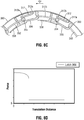
- Link 300 is configured such that a high magnitude of force (F magnitude ) is initially required as sphincter assist device 1000 begins to transition from the closed configuration towards the open configuration and a low, near constant restoring force is maintained once link 300 transitions into the open configuration.
- F magnitude a high magnitude of force
- link 300 maintains an initial force requirement to translate sphincter assist device 1000 from the closed configuration towards to open configuration, while and also being configured to assist sphincter assist device 1000, and thus the sphincter, easily return from the open configuration to the closed configuration. More particularly, FIG.
- FIG. 8D illustrates an exemplary graph depicting (F magnitude ) versus (T distance ) from the closed configuration to the open configuration of link 300, wherein a high magnitude of force (F magnitude ) is required to begin the initial transition of sphincter assist device 1000 from the closed configuration towards the open configuration and a low, near constant magnitude of force (F magnitude ) is maintained in the open configuration.
- link 300 may be tailored to provide a desired initial magnitude of force in the closed configuration and a desired low, near constant magnitude of force in the open configuration such that link 300, and thus sphincter assist device 1000, may be tailored and configured for a given sphincter of a patient.
- a plurality of interconnected links 300 may make up sphincter assist device 1000, where each link 300 is sequentially coupled to an adjacent link 300 to form a ring which circumscribes the sphincter. It should be appreciated that each link 300 which makes up sphincter assist device 1000 is generally identical, unless otherwise descried herein.
- Link 300 includes a body section 310 and a latch cam 350 extending therefrom.
- Body section 310 defines a spring mechanism 312 disposed within, and biased towards a cavity 314 of body section 310.
- Body section 310 further defines a channel 334 defined upon a first wall 330 of body section 310, wherein channel 334 is in communication with cavity 314.
- Body section 310 additionally includes a recess 336 disposed on an external surface thereof which extends from a second wall of 332.
- a finger 338 extends from first wall 330 and is configured to engage recess 336 of an adjacent link 300 ( FIGS. 8B and 8C ).
- Finger 338 is configured to be flexible and reduce tissue pinch points, blowouts, or tissue erosion by blocking or inhibiting tissue from entering into body section 310 when in the open configuration.
- Latch cam 350 includes an arm 352 extending from second wall 330 of body section 310 and a cam 354 disposed near an end of arm 352. Arm 352 is configured to be received within channel 334 of an adjacent link 300, where cam 350 is configured to reside within cavity 314 and engage spring mechanism 312 of the adjacent link 300.
- Spring mechanism 312 defines at least two separate force zones, a high force zone 312a and a low force zone 312b. It should be appreciated that the bias, curvature, and shape of spring mechanism 312 dictates the total force profile of link 300 as sphincter assist device 1000 transitions between the closed and open configurations. More particularly, spring mechanism 312 is configured to be biased into a position within cavity 314. As a first link 300 translates away from an adjacent link 300 in the direction of arrow "C" ( FIG. 8B ), i.e., as sphincter assist device 1000 transitions from the closed configuration towards the open configuration, arm 352 translates within channel 334 of the adjacent link 300 and cam 354 rides along spring mechanism 312 of the adjacent link 300.
- a ramped portion defines the high force zone 312a and a near flat portion defines the low force zone 312b.
- spring mechanism 312 may define a plurality of high force zones 312a or low force zones 312b, and/or define an angled surface of varying degrees to adjust the high force zone 312a or low force zone 312b, to further tailor and configure the non-linear force profile of link 300, and thus sphincter device 1000, for a given sphincter of a patient.
- Link 300 may further include an elastic band 360 which circumscribes the plurality of links 300 making up sphincter assist device 1000.
- Elastic band 360 is configured to provide a low spring force radially inward to facilitate closure of sphincter assist device 1000.
- sphincter assist device 1000 may be further tailored and configured for a given sphincter of a patient.
Landscapes
- Health & Medical Sciences (AREA)
- Life Sciences & Earth Sciences (AREA)
- General Health & Medical Sciences (AREA)
- Public Health (AREA)
- Animal Behavior & Ethology (AREA)
- Vascular Medicine (AREA)
- Engineering & Computer Science (AREA)
- Biomedical Technology (AREA)
- Heart & Thoracic Surgery (AREA)
- Veterinary Medicine (AREA)
- Urology & Nephrology (AREA)
- Transplantation (AREA)
- Oral & Maxillofacial Surgery (AREA)
- Cardiology (AREA)
- Obesity (AREA)
- Surgery (AREA)
- Child & Adolescent Psychology (AREA)
- Orthopedic Medicine & Surgery (AREA)
- Nursing (AREA)
- Molecular Biology (AREA)
- Reproductive Health (AREA)
- Nuclear Medicine, Radiotherapy & Molecular Imaging (AREA)
- Medical Informatics (AREA)
- Prostheses (AREA)
Applications Claiming Priority (1)
| Application Number | Priority Date | Filing Date | Title |
|---|---|---|---|
| US15/595,624 US10603199B2 (en) | 2017-05-15 | 2017-05-15 | Sphincter assist device and method of use |
Publications (1)
| Publication Number | Publication Date |
|---|---|
| EP3403614A1 true EP3403614A1 (fr) | 2018-11-21 |
Family
ID=62200254
Family Applications (1)
| Application Number | Title | Priority Date | Filing Date |
|---|---|---|---|
| EP18171989.9A Withdrawn EP3403614A1 (fr) | 2017-05-15 | 2018-05-14 | Dispositif d'assistance de sphincter |
Country Status (2)
| Country | Link |
|---|---|
| US (2) | US10603199B2 (fr) |
| EP (1) | EP3403614A1 (fr) |
Families Citing this family (11)
| Publication number | Priority date | Publication date | Assignee | Title |
|---|---|---|---|---|
| MX348673B (es) | 2008-05-01 | 2017-06-23 | Convatec Tech Inc * | Dispositivo de drenaje rectal. |
| CN103533969A (zh) | 2011-03-17 | 2014-01-22 | 康沃特克科技公司 | 高阻隔性弹性体粪便导管或造口袋 |
| CA2918607C (fr) | 2013-08-01 | 2024-02-20 | Convatec Technologies Inc. | Raccord de poche a fermeture automatique |
| US10603199B2 (en) | 2017-05-15 | 2020-03-31 | Covidien Lp | Sphincter assist device and method of use |
| GB201721956D0 (en) | 2017-12-27 | 2018-02-07 | Convatec Ltd | Female catheter locator tip |
| GB201721955D0 (en) | 2017-12-27 | 2018-02-07 | Convatec Ltd | Catheter wetting devices |
| US20200113570A1 (en) * | 2018-10-11 | 2020-04-16 | Moises Jacobs | Gastroesophageal reflux treatment system, method, and device |
| US10842496B2 (en) * | 2018-12-17 | 2020-11-24 | Ethicon Llc | Implantable sphincter assistance device with tuned magnetic features |
| US11298136B2 (en) * | 2018-12-19 | 2022-04-12 | Cilag Gmbh International | Implantable sphincter assistance device with deformable elements |
| AU2020290905A1 (en) | 2019-06-11 | 2021-11-18 | Convatec Technologies Inc. | Urine collection bags for use with catheter products, kits incorporating the same, and methods therefor |
| US12213675B2 (en) * | 2021-12-16 | 2025-02-04 | Cilag Gmbh International | Implantable sphincter assistance device with holding, aligning or clamping features integrated into housing |
Citations (5)
| Publication number | Priority date | Publication date | Assignee | Title |
|---|---|---|---|---|
| WO2003101352A1 (fr) * | 2002-05-31 | 2003-12-11 | Textile Hi Tec | Anneau gastrique |
| US20050283235A1 (en) * | 2002-04-26 | 2005-12-22 | Torax Medical, Inc. | Methods and apparatus for treating body tissue sphincters and the like |
| WO2009029228A2 (fr) * | 2007-08-27 | 2009-03-05 | Torax Medical, Inc. | Anneau gastrique magnétique ou équivalent et procédés apparentés |
| FR2944432A1 (fr) * | 2009-04-21 | 2010-10-22 | Cie Euro Etude Rech Paroscopie | Anneau chirurgical a construction assemblee |
| US20120095484A1 (en) * | 2010-10-19 | 2012-04-19 | Allergan, Inc. | Articulated gastric implant clip |
Family Cites Families (14)
| Publication number | Priority date | Publication date | Assignee | Title |
|---|---|---|---|---|
| US6464628B1 (en) | 1999-08-12 | 2002-10-15 | Obtech Medical Ag | Mechanical anal incontinence |
| US7175589B2 (en) | 2002-07-02 | 2007-02-13 | The Foundry Inc. | Methods and devices for luminal and sphincter augmentation |
| US7351198B2 (en) | 2004-06-02 | 2008-04-01 | Ethicon Endo-Surgery, Inc. | Implantable adjustable sphincter system |
| US7763065B2 (en) * | 2004-07-21 | 2010-07-27 | Reva Medical, Inc. | Balloon expandable crush-recoverable stent device |
| WO2006026509A2 (fr) | 2004-08-25 | 2006-03-09 | Pavad Medical, Inc. | Sphincter artificiel |
| US7458930B2 (en) | 2004-12-29 | 2008-12-02 | Nitinol Development Corporation | Artificial sphincter with variable viscosity fluid-filled collar |
| US20060276812A1 (en) | 2005-04-04 | 2006-12-07 | Hill James W | Dynamic reinforcement of the lower esophageal sphincter |
| US9149378B2 (en) * | 2005-08-02 | 2015-10-06 | Reva Medical, Inc. | Axially nested slide and lock expandable device |
| US20090209995A1 (en) | 2008-02-14 | 2009-08-20 | Byrum Randal T | Implantable adjustable sphincter system |
| US20110218388A1 (en) | 2010-03-02 | 2011-09-08 | Vibrant Med-El Hearing Technology Gmbh | Ring Magnet for Obesity Management |
| WO2013028390A1 (fr) * | 2011-08-23 | 2013-02-28 | Torax Medical, Inc. | Implant médical avec aimants flottants |
| CN102488571B (zh) | 2011-12-12 | 2014-07-30 | 音络(北京)科技发展有限公司 | 一种磁环人工括约肌及其制造和应用方法 |
| WO2013165541A1 (fr) | 2012-05-02 | 2013-11-07 | Ams Research Corporation | Sphincter artificiel passif |
| US10603199B2 (en) | 2017-05-15 | 2020-03-31 | Covidien Lp | Sphincter assist device and method of use |
-
2017
- 2017-05-15 US US15/595,624 patent/US10603199B2/en active Active
-
2018
- 2018-05-14 EP EP18171989.9A patent/EP3403614A1/fr not_active Withdrawn
-
2020
- 2020-03-25 US US16/829,028 patent/US11318032B2/en active Active
Patent Citations (5)
| Publication number | Priority date | Publication date | Assignee | Title |
|---|---|---|---|---|
| US20050283235A1 (en) * | 2002-04-26 | 2005-12-22 | Torax Medical, Inc. | Methods and apparatus for treating body tissue sphincters and the like |
| WO2003101352A1 (fr) * | 2002-05-31 | 2003-12-11 | Textile Hi Tec | Anneau gastrique |
| WO2009029228A2 (fr) * | 2007-08-27 | 2009-03-05 | Torax Medical, Inc. | Anneau gastrique magnétique ou équivalent et procédés apparentés |
| FR2944432A1 (fr) * | 2009-04-21 | 2010-10-22 | Cie Euro Etude Rech Paroscopie | Anneau chirurgical a construction assemblee |
| US20120095484A1 (en) * | 2010-10-19 | 2012-04-19 | Allergan, Inc. | Articulated gastric implant clip |
Also Published As
| Publication number | Publication date |
|---|---|
| US20180325643A1 (en) | 2018-11-15 |
| US20200222220A1 (en) | 2020-07-16 |
| US11318032B2 (en) | 2022-05-03 |
| US10603199B2 (en) | 2020-03-31 |
Similar Documents
| Publication | Publication Date | Title |
|---|---|---|
| US11318032B2 (en) | Sphincter assist device and method of use | |
| US6764518B2 (en) | Prosthesis for controlling the direction of flow in a duct of a living organism | |
| US10405865B2 (en) | Method for assisting a sphincter | |
| US10716570B2 (en) | Magnetic restraint mechanism for a sphincter assist device | |
| US10828140B2 (en) | Artificial urinary sphincter device | |
| CA2472700C (fr) | Bande implantable avec mecanisme de fixation ayant des proprietes de materiaux differentes | |
| CN114126506B (zh) | 闭合腹疝和减少复发的腹部闭合方法和器械的变型 | |
| US20070213836A1 (en) | Surgical Ring with an Improved Closure System | |
| US9463106B2 (en) | Catheter with releasable balloon and related methods | |
| CN110785202A (zh) | 用于创建永久性引流瘘管的系统和方法 | |
| US20100331825A1 (en) | Indwelling urinary catheter with self-retaining mechanism | |
| EP2269540A1 (fr) | Sphincter de contraction artificiel | |
| BRPI0603744B1 (pt) | Banda gástrica com um conjunto de engate | |
| KR20050083700A (ko) | 수압식 이식물의 작동을 위한 이식가능 펌프 | |
| US10219808B2 (en) | Partial cuff | |
| CN108778197A (zh) | 括约肌型肠道阀 | |
| WO2018001192A1 (fr) | Dispositif d'implantation anti-reflux gastro-œsophagien | |
| US20210205084A1 (en) | Penile implant | |
| US20140378746A1 (en) | Artificial sphincter | |
| CN118615053A (zh) | 一种人工尿道括约肌锁紧装置 | |
| US10716658B2 (en) | Absorbable polymer for a magnetic sphincter assist device | |
| CN109481079A (zh) | 一种磁控尿道阀 | |
| WO2016005824A1 (fr) | Dispositif intra-urétral pour le traitement de l'incontinence urinaire chez les femmes | |
| CN110270008B (zh) | 一种磁控尿道阀 | |
| EP2092912A1 (fr) | Structure contractile artificielle |
Legal Events
| Date | Code | Title | Description |
|---|---|---|---|
| PUAI | Public reference made under article 153(3) epc to a published international application that has entered the european phase |
Free format text: ORIGINAL CODE: 0009012 |
|
| STAA | Information on the status of an ep patent application or granted ep patent |
Free format text: STATUS: REQUEST FOR EXAMINATION WAS MADE |
|
| 17P | Request for examination filed |
Effective date: 20180514 |
|
| AK | Designated contracting states |
Kind code of ref document: A1 Designated state(s): AL AT BE BG CH CY CZ DE DK EE ES FI FR GB GR HR HU IE IS IT LI LT LU LV MC MK MT NL NO PL PT RO RS SE SI SK SM TR |
|
| AX | Request for extension of the european patent |
Extension state: BA ME |
|
| RBV | Designated contracting states (corrected) |
Designated state(s): AL AT BE BG CH CY CZ DE DK EE ES FI FR GB GR HR HU IE IS IT LI LT LU LV MC MK MT NL NO PL PT RO RS SE SI SK SM TR |
|
| STAA | Information on the status of an ep patent application or granted ep patent |
Free format text: STATUS: EXAMINATION IS IN PROGRESS |
|
| 17Q | First examination report despatched |
Effective date: 20220328 |
|
| STAA | Information on the status of an ep patent application or granted ep patent |
Free format text: STATUS: THE APPLICATION IS DEEMED TO BE WITHDRAWN |
|
| 18D | Application deemed to be withdrawn |
Effective date: 20241203 |