EP3403863B1 - Spülauswerferanordnung für ein fahrzeug - Google Patents
Spülauswerferanordnung für ein fahrzeug Download PDFInfo
- Publication number
- EP3403863B1 EP3403863B1 EP17171712.7A EP17171712A EP3403863B1 EP 3403863 B1 EP3403863 B1 EP 3403863B1 EP 17171712 A EP17171712 A EP 17171712A EP 3403863 B1 EP3403863 B1 EP 3403863B1
- Authority
- EP
- European Patent Office
- Prior art keywords
- purge
- flow
- fluid passage
- flow port
- engine
- Prior art date
- Legal status (The legal status is an assumption and is not a legal conclusion. Google has not performed a legal analysis and makes no representation as to the accuracy of the status listed.)
- Active
Links
Images



Classifications
-
- B—PERFORMING OPERATIONS; TRANSPORTING
- B60—VEHICLES IN GENERAL
- B60K—ARRANGEMENT OR MOUNTING OF PROPULSION UNITS OR OF TRANSMISSIONS IN VEHICLES; ARRANGEMENT OR MOUNTING OF PLURAL DIVERSE PRIME-MOVERS IN VEHICLES; AUXILIARY DRIVES FOR VEHICLES; INSTRUMENTATION OR DASHBOARDS FOR VEHICLES; ARRANGEMENTS IN CONNECTION WITH COOLING, AIR INTAKE, GAS EXHAUST OR FUEL SUPPLY OF PROPULSION UNITS IN VEHICLES
- B60K15/00—Arrangement in connection with fuel supply of combustion engines or other fuel consuming energy converters, e.g. fuel cells; Mounting or construction of fuel tanks
- B60K15/03—Fuel tanks
- B60K15/035—Fuel tanks characterised by venting means
-
- F—MECHANICAL ENGINEERING; LIGHTING; HEATING; WEAPONS; BLASTING
- F02—COMBUSTION ENGINES; HOT-GAS OR COMBUSTION-PRODUCT ENGINE PLANTS
- F02M—SUPPLYING COMBUSTION ENGINES IN GENERAL WITH COMBUSTIBLE MIXTURES OR CONSTITUENTS THEREOF
- F02M25/00—Engine-pertinent apparatus for adding non-fuel substances or small quantities of secondary fuel to combustion-air, main fuel or fuel-air mixture
- F02M25/08—Engine-pertinent apparatus for adding non-fuel substances or small quantities of secondary fuel to combustion-air, main fuel or fuel-air mixture adding fuel vapours drawn from engine fuel reservoir
- F02M25/0836—Arrangement of valves controlling the admission of fuel vapour to an engine, e.g. valve being disposed between fuel tank or absorption canister and intake manifold
-
- F—MECHANICAL ENGINEERING; LIGHTING; HEATING; WEAPONS; BLASTING
- F02—COMBUSTION ENGINES; HOT-GAS OR COMBUSTION-PRODUCT ENGINE PLANTS
- F02M—SUPPLYING COMBUSTION ENGINES IN GENERAL WITH COMBUSTIBLE MIXTURES OR CONSTITUENTS THEREOF
- F02M25/00—Engine-pertinent apparatus for adding non-fuel substances or small quantities of secondary fuel to combustion-air, main fuel or fuel-air mixture
- F02M25/08—Engine-pertinent apparatus for adding non-fuel substances or small quantities of secondary fuel to combustion-air, main fuel or fuel-air mixture adding fuel vapours drawn from engine fuel reservoir
- F02M25/0854—Details of the absorption canister
-
- F—MECHANICAL ENGINEERING; LIGHTING; HEATING; WEAPONS; BLASTING
- F02—COMBUSTION ENGINES; HOT-GAS OR COMBUSTION-PRODUCT ENGINE PLANTS
- F02M—SUPPLYING COMBUSTION ENGINES IN GENERAL WITH COMBUSTIBLE MIXTURES OR CONSTITUENTS THEREOF
- F02M25/00—Engine-pertinent apparatus for adding non-fuel substances or small quantities of secondary fuel to combustion-air, main fuel or fuel-air mixture
- F02M25/08—Engine-pertinent apparatus for adding non-fuel substances or small quantities of secondary fuel to combustion-air, main fuel or fuel-air mixture adding fuel vapours drawn from engine fuel reservoir
- F02M25/0872—Details of the fuel vapour pipes or conduits
-
- F—MECHANICAL ENGINEERING; LIGHTING; HEATING; WEAPONS; BLASTING
- F02—COMBUSTION ENGINES; HOT-GAS OR COMBUSTION-PRODUCT ENGINE PLANTS
- F02M—SUPPLYING COMBUSTION ENGINES IN GENERAL WITH COMBUSTIBLE MIXTURES OR CONSTITUENTS THEREOF
- F02M35/00—Combustion-air cleaners, air intakes, intake silencers, or induction systems specially adapted for, or arranged on, internal-combustion engines
- F02M35/10—Air intakes; Induction systems
- F02M35/1015—Air intakes; Induction systems characterised by the engine type
- F02M35/10157—Supercharged engines
-
- F—MECHANICAL ENGINEERING; LIGHTING; HEATING; WEAPONS; BLASTING
- F02—COMBUSTION ENGINES; HOT-GAS OR COMBUSTION-PRODUCT ENGINE PLANTS
- F02M—SUPPLYING COMBUSTION ENGINES IN GENERAL WITH COMBUSTIBLE MIXTURES OR CONSTITUENTS THEREOF
- F02M35/00—Combustion-air cleaners, air intakes, intake silencers, or induction systems specially adapted for, or arranged on, internal-combustion engines
- F02M35/10—Air intakes; Induction systems
- F02M35/10209—Fluid connections to the air intake system; their arrangement of pipes, valves or the like
- F02M35/10222—Exhaust gas recirculation [EGR]; Positive crankcase ventilation [PCV]; Additional air admission, lubricant or fuel vapour admission
-
- B—PERFORMING OPERATIONS; TRANSPORTING
- B60—VEHICLES IN GENERAL
- B60K—ARRANGEMENT OR MOUNTING OF PROPULSION UNITS OR OF TRANSMISSIONS IN VEHICLES; ARRANGEMENT OR MOUNTING OF PLURAL DIVERSE PRIME-MOVERS IN VEHICLES; AUXILIARY DRIVES FOR VEHICLES; INSTRUMENTATION OR DASHBOARDS FOR VEHICLES; ARRANGEMENTS IN CONNECTION WITH COOLING, AIR INTAKE, GAS EXHAUST OR FUEL SUPPLY OF PROPULSION UNITS IN VEHICLES
- B60K15/00—Arrangement in connection with fuel supply of combustion engines or other fuel consuming energy converters, e.g. fuel cells; Mounting or construction of fuel tanks
- B60K15/03—Fuel tanks
- B60K15/035—Fuel tanks characterised by venting means
- B60K15/03504—Fuel tanks characterised by venting means adapted to avoid loss of fuel or fuel vapour, e.g. with vapour recovery systems
- B60K2015/03514—Fuel tanks characterised by venting means adapted to avoid loss of fuel or fuel vapour, e.g. with vapour recovery systems with vapor recovery means
-
- F—MECHANICAL ENGINEERING; LIGHTING; HEATING; WEAPONS; BLASTING
- F02—COMBUSTION ENGINES; HOT-GAS OR COMBUSTION-PRODUCT ENGINE PLANTS
- F02B—INTERNAL-COMBUSTION PISTON ENGINES; COMBUSTION ENGINES IN GENERAL
- F02B39/00—Component parts, details, or accessories relating to, driven charging or scavenging pumps, not provided for in groups F02B33/00 - F02B37/00
-
- Y—GENERAL TAGGING OF NEW TECHNOLOGICAL DEVELOPMENTS; GENERAL TAGGING OF CROSS-SECTIONAL TECHNOLOGIES SPANNING OVER SEVERAL SECTIONS OF THE IPC; TECHNICAL SUBJECTS COVERED BY FORMER USPC CROSS-REFERENCE ART COLLECTIONS [XRACs] AND DIGESTS
- Y02—TECHNOLOGIES OR APPLICATIONS FOR MITIGATION OR ADAPTATION AGAINST CLIMATE CHANGE
- Y02T—CLIMATE CHANGE MITIGATION TECHNOLOGIES RELATED TO TRANSPORTATION
- Y02T10/00—Road transport of goods or passengers
- Y02T10/10—Internal combustion engine [ICE] based vehicles
- Y02T10/12—Improving ICE efficiencies
Definitions
- the disclosure will be described in relation to a car, the disclosure is not restricted to this particular vehicle, but may as well be installed in other type of vehicles such as minivans, recreational vehicles, off-road vehicles, and heavy-duty vehicles, such as trucks, buses and construction equipment.
- Vehicle engines in particular petrol fuel-powered combustion engines but also other engines, are typically connected to a fuel system including a fuel tank and other components, such as for example a fuel pump and fuel lines, configured to provide fuel to the engine or the engine system.
- a fuel system including a fuel tank and other components, such as for example a fuel pump and fuel lines, configured to provide fuel to the engine or the engine system.
- a majority of these systems also include a so called fuel evaporation purge (EVAP) system for preventing fuel vapour in the fuel tank from escaping into the atmosphere.
- EVAP fuel evaporation purge
- a fuel system is typically not allowed to leak more fuel vapour in the atmosphere than legislations permit.
- the EVAP system is generally configured to trap fuel vapour from the fuel tank and temporarily store them in a charcoal canister.
- the fuel vapour is purged from the canister and burned inside the engine.
- the canister needs to be drained of hydrocarbons to make sure that emissions are still kept to a satisfied level.
- the EVAP system may also include a purge valve or other control mechanisms adapted to control the amount of fuel vapour intended to be purged from the charcoal canister.
- the purge valve is controlled by the engine computer. When the engine is off, the purge valve is closed. When the engine is running and fully warmed up, the engine computer gradually opens the purge valve to permit some amount of fuel vapour to be transferred from the charcoal canister to the engine.
- Some systems may include a purge ejector assembly to further improve the process of emptying the canister in an efficient way, which may operate both during low pressure and boost pressure conditions of the vehicle's engine.
- a purge ejector system may be designed in several different ways, and includes a purge ejector and one or several valves to control the flow of fuel vapour between the components making up the EVAP system and the engine system.
- US2015/159601 discloses a purge injector assembly according to the preamble of claim 1.
- the purge ejector or the purge ejector assembly for the engine can be installed in a known or commercially available vehicle without substantial changes to the fuel system or the EVAP system, while enabling an effective purge of the canister during operation of the engine system. Further, it is also desired to have a purge ejector solution having a high efficiency during both low pressure and boost pressure conditions of the engine in order to minimize the energy used to purge the fuel vapours from the canister.
- the present invention provides a purge ejector assembly capable of controlling the purge flow both when the engine is operated under low pressure and boost pressure conditions.
- the purge ejector assembly is capable of controlling the process of emptying the canister of a vehicle fuel system during various engine conditions, i.e. during idle at the driving cycles as well as during boost pressure at the driving cycles. This may be particularly important for vehicles with small engine displacement and so called stop/start functions as well as for vehicles with hybrid engines.
- the advantages described above are also believed to further contribute to better meet prevailing regulations with regards to exhaust and fuel emissions. As such, the example embodiments of the present disclosure are capable of improving the general performance of the purge ejector assembly.
- the converging part is formed by an end portion of the second fluid passage extending into the first fluid passage.
- the end portion of the second fluid passage is used for establishing the converging part, which provides a simple and reliable construction.
- the converging part is formed by a pipe contraction within the first fluid passage. This provides an alternative way to construct the converging part, which provides flexibility in the shaping of the flow of air around the nozzle opening.
- the purge ejector assembly further comprises a third fluid passage establishing fluid communication between the purge flow port and the engine flow port, and a third valve disposed in the third fluid passage at a position in-between the engine flow port and the purge flow port.
- the third valve is configured to permit fluid to flow through the third valve from the purge flow port towards the engine flow port, while restricting fluid to flow through the third valve from the engine flow port towards the purge flow port, thereby enabling evaporated fuel to flow in the third fluid passage from the canister purge passage to the engine flow port when a low pressure is applied to the engine flow port.
- the arrangements and locations of the first valve, the second valve and the third valve allows for determining and controlling the purge flow in both low pressure conditions and boost pressure conditions. In this way, the canister can be purged in different driving situations of the vehicle.
- the disclosure also relates to a method for ejecting evaporated fuel in a vehicle with a purge ejector assembly, where a flow of air is disposed in a first fluid passage of the purge ejector assembly around an nozzle opening, where the nozzle opening is arranged inside the first fluid passage such that the flow of air in the first fluid passage is flowing around the nozzle opening. Further, the disclosure relates to a vehicle comprising a purge ejector assembly.
- the vehicle fuel system 100 is schematically shown.
- the vehicle fuel system may also be denoted as the fuel system 100.
- the vehicle fuel evaporation purge system 102 may also be denoted as the evaporation purge system, the evaporative emission control system, or simply as the EVAP system.
- the fuel evaporation purge system 102 is typically, although strictly not necessary, a part of the fuel system.
- the fuel system 100 is in this example embodiment connected to an engine or engine system 180 of the vehicle.
- the engine system 180 includes the engine of the vehicle, and the engine comprises one or more cylinders.
- the engine system 180 has an engine inlet manifold 104, also known as manifold or intake, and an engine exhaust.
- the engine inlet manifold 104 has a throttle that is in fluid communication with the engine inlet manifold 104.
- the engine exhaust may include an exhaust manifold connected to an exhaust passage configured to direct exhaust gas to the atmosphere.
- a boosted engine operation may be performed by the engine system 180.
- the operation of the compressor 188 to obtain a suitable boost pressure may vary depending on type of vehicle and type of engine.
- the arrangement, components and functions of the air intake unit 185 and the compressor 188 in view of the engine system 180 may vary depending on type of vehicle, type of engine system and type of fuel system. As these components and their functions are well-known in the art and selected depending on type of vehicle and type system, no further details are described herein.
- the canister 110 is connected to the fuel tank 140 via an evaporation vent passage 142. As such, the canister 110 can receive fuel vapours from the fuel tank 140 via the evaporation vent passage 142.
- the EVAP system may include one single canister 110. However, in other examples, the EVAP system may include a number of inter-connected canisters. From the above, it should be understood that when fuel is filled into the fuel tank 140, fuel vapours from the fuel tank 140 can be vented via the evaporation vent passage 142 to the canister 110 in order to avoid that hydrocarbons are released into the environment.
- the purge valve 90 may for instance be operated by software and set to open and close on the basis of the duty cycle of a solenoid connected to the purge valve 90. For instance, the purge valve 90 may be set to a closed state so that no fuel vapours are purged via the canister purge passage 92. In contrast, when the purge valve 90 is set to an open state, it becomes possible to purge fuel vapours from the canister 110.
- the purge valve 90 may be a conventional check valve, a solenoid or the like.
- the evaporation fuel purge system 102 comprises the purge ejector assembly 10 according to various example embodiments described herein.
- the purge ejector assembly 10 is disposed at a position in the canister purge passage 92 between the purge valve 90 and the engine inlet manifold 104.
- the purge ejector assembly 10 may be installed in other locations of the EVAP system and/or the canister purge passage 92.
- the canister purge passage 92 is connected to the purge ejector assembly 10, which is then connected to the engine system 180 via the engine inlet manifold 104.
- the purge ejector assembly 10 comprises an ejector pump of the vacuum ejector pump type, using the known Venturi effect to convert the pressure energy of a motive fluid to velocity energy, which creates a low pressure zone that draws in and entrains a suction fluid.
- the details of the purge ejector assembly 10 will be described more in detail below.
- Figure 3 schematically shows the purge ejector assembly 10 according to an example embodiment, in which the purge ejector assembly 10 is subjected to a low pressure so that the purge ejector assembly 10 is set to operate under so called low pressure conditions.
- the air and fuel mixture is sucked into the engine in the naturally aspirated mode of the engine, where the compressor 188 is not used.
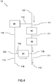
- Figure 4 schematically illustrates an example embodiment of the purge ejector assembly 10 in figure 3 , in which the purge ejector assembly 10 is subjected to a boost pressure so that the purge ejector assembly 10 is set to operate under the so called boost pressure conditions, as described above.
- the EVAP system 102 in figures 3 and 4 comprises the purge ejector assembly 10, where the purge ejector assembly 10 may be provided as a single unit. However, the purge ejector assembly 10 may in other examples also be provided as separate components in the EVAP system, which components in combination are making up the purge ejector assembly 10.
- the purge ejector assembly 10 comprises a first fluid passage 111 having an engine flow port 122 and an air channel flow port 112 in fluid communication with each other.
- the first fluid passage 111 is adapted to transport fluids, such as air and fuel vapours, and unless the first fluid passage 111 is restricted by a valve as mentioned below, the first fluid passage 111 is capable of transporting fluids in both directions between the engine flow port 122 and air channel flow port 112.
- the first fluid passage 111 is arranged for guiding a stream of pressurized air from the compressor 188, which is flowing from the engine flow port 122 in a direction towards the air channel flow port 112.
- the first fluid passage 111 may be arranged as a pipe structure in which the pressurized air is flowing.
- the engine flow port 122 is arranged to be in fluid communication with the compressor 188 via the engine inlet manifold 104. In this way, a part of the pressurized air from the compressor 188 is guided through the engine inlet manifold 104 and further through the first fluid passage 111.
- the air channel flow port 112 is arranged to be in fluid communication with an air inlet channel arranged between the air intake unit 185 and the compressor 188, as shown in figure 1 , so that the flow of air through the first fluid passage 111 may flow back to the inlet of the compressor 188.
- the air intake unit 185 may as described above typically be connected to the compressor 188. However, this example is only one of many possible examples of a fluid connection between the various components of the system.
- the flow of air in the first fluid passage 111 may be regarded as the motive fluid in the purge ejector assembly 10 having a first pressure level P1, essentially corresponding to the boost pressure from the compressor 188.
- the purge flow port 118 is connectable to the canister purge passage 92 enabling evaporated fuel to flow in the second fluid passage 115 from the canister purge passage 92 via the purge flow port 118 to the air channel flow port 112.
- the air channel flow port 112 is as described above arranged to be in fluid communication with the air inlet channel arranged between the air intake unit 185 and the compressor 188, as shown in figure 1 , so that the flow of fuel vapour through the second fluid passage 115 may flow to the inlet of the compressor 188.
- the second fluid passage 115 is thus arranged for evacuating or purging evaporated fuel from the canister 110 via the canister purge passage 92.
- the flow of air in the first fluid passage 111 is mixed with the flow of fuel vapour from the second fluid passage 115 after the nozzle opening 116.
- the mixing of the flow of air and the flow of fuel vapour will thus take place within the first fluid passage and be further transported through the air channel flow port 112.
- a flow shape unit 20 is disposed within the first fluid passage 111 between the engine flow port 122 and the air channel flow port 112, and the flow shape unit 20 is configured to raise the flow velocity of air flowing in a direction from the engine flow port 122 to the air channel flow port 112 when the first pressure level P1 is applied to the engine flow port 122 during boost pressure conditions upon operation of the compressor 188, thereby subjecting the second fluid passage 115 to a second pressure level P2, which second pressure level P2 due to the Venturi effect is lower than the first pressure level P1.
- This effect is well known in the art and is commonly used in different ejector applications.
- the system is designed so that under boost pressure, the second pressure level P2 is lower than the pressure level in the canister 110 and in the canister purge passage 92, and in this way the fuel vapour is sucked from the canister 110, via the canister purge passage 92 through the second fluid passage 115.
- the flow of fuel vapour in the second fluid passage 111 may be regarded as a suction fluid in the purge ejector assembly 10 having the second pressure level P2.
- the first pressure level P1 may vary in the system depending on the pressure output from the compressor 188.
- the purge ejector assembly 10 may based on system parameters be designed so that a suitable second pressure level P2 is achieved during boost pressure conditions.
- the flow of air in the first fluid passage 111 is flowing around the nozzle opening 116 along an inner wall 117 of the first fluid passage 111.
- the nozzle opening 116 has an essentially circular cross-sectional shape and the inner wall 117 of the first fluid passage 111 has an essentially circular cross-sectional shape.
- the flow of air in the first fluid passage 111 may be arranged so that it has an essentially annular cross-sectional shape when flowing around the nozzle opening 116, in a direction along the first fluid passage 111 from the engine flow port 122 towards the air channel flow port 112. Tests have shown that the flow of air with annular cross-sectional shape around the nozzle opening 116 establishes a highly efficient suction effect in the second fluid passage 115.
- the canister 100 may be purged in an efficent way with low energy consumption with this specific design of the purge ejector assembly 10.
- Low energy usage in the purge ejector assembly 10 is important in order to support the lowering of the total emissions of the vehicle.
- the flow shape unit 20 comprises a converging part 119, which is configured to raise the flow velocity of the flow of air from the engine flow port 122 to the air channel flow port 112.
- the converging part 119 may be formed by an end portion 120 of the second fluid passage 115 extending into the first fluid passage 111. Due to the pipe-like configuration of the second fluid passage 115, the end portion 120 may as an example be funnel-shaped in order to form the converging part 119, as shown in figure 5a , where the end portion 120 forming the nozzle opening 116 in a cross-sectional view is widened in a curve towards the inner wall 117 of the first fluid passage 111.
- the boost pressure is establishing the flow of air with the first pressure level P1 in the first fluid passage 111, and the air flow entering the first fluid passage 111 is the motive fluid that is operating the purge ejector assembly 10 under boost pressure conditions.
- the air flow is reaching the flow shape unit 20, the velocity of the air flow increases and due to this effect the second pressure level P2 is established in the second fluid passage 115.
- the evaporated fuel can be purged from the canister 110 and flow through the canister purge passage 92 and further into the purge flow port 118 of the second fluid passage 115.
- the flow of evaporated fuel will exit the second fluid passage when reaching the nozzle opening 116, and after the nozzle opening 116, the flow of air in the first fluid passage 111 will mix with the fuel vapour from the second fluid passage 115, and the mixed fluids will flow out from the first fluid passage 111 through the air channel flow port 112 and further to the air inlet channel arranged between the air intake unit 185 and the compressor 188.
- the converging part 119 is formed by a pipe contraction 121 within the first fluid passage 111.
- the flow shape unit 20 may also comprise a diverging part 123 arranged in the flow direction after the converging part 119, as shown in figure 5b .
- the diverging part 123 may be formed by a pipe expansion 125 within the first fluid passage 111.
- the converging part 119 and the diverging part 123 are in a conventional way used to control the flow in the first fluid passage.
- the pipe contraction 121 may for example be formed through shaping of the inner wall 117 of the first fluid passage 111, as shown in figure 5b .
- the purge ejector assembly 10 may further comprise a first valve 30 disposed in the first fluid passage 111 at a position in-between the engine flow port 122 and the flow shape unit 20, as shown in figures 3 and 4 .
- the first valve 30 is configured to permit fluid to flow through the first valve 30 from the engine flow port 122 towards the flow shape unit 20, while restricting fluid to flow through the first valve from the flow shape unit 20 towards the engine flow port 122.
- a second valve 50 may be disposed in the second fluid passage 115. The second valve 50 is configured to permit fluid to flow through the second valve 50 from the purge flow port 118 towards the air channel flow port 112, while restricting fluid to flow through the second valve 50 from the air channel flow port 112 towards the purge flow port 118.
- the first pressure level P1 is generated by the compressor 188 in the first fluid passage 111 so that the second fluid passage 115 extending between the purge flow port 118 and the air channel flow port 112, is subjected to the second pressure level P2, which is lower than the first pressure level P1 and also lower than the pressure level in the canister 110.
- the second pressure level P2 in the second fluid passage 115 enables the canister 110 to be emptied via the second fluid passage 115 to the air channel flow port 112 when the system is operating under boost pressure.
- the first pressure level P1 generated in the first fluid passage 111 by the compressor 188 is forming the lower second pressure level P2 in the second fluid passage 115.
- the second valve 50 may be a check valve. Also, it is to be noted that unless the second fluid passage 115 is restricted by the second valve 50, the second fluid passage 115 is capable of transporting fluid in both directions between the purge flow port 118 and the air channel flow port 112.
- the second fluid passage 115 and the second valve 50 are configured to restrict fluid to flow through the second valve 50 from the air channel flow port 112 toward the purge flow port 118.
- the purge ejector assembly 10 may also comprise the third fluid passage 113 establishing fluid communication between the purge flow port 118 and the engine flow port 122, as shown in figures 3 and 4 .
- the third valve 40 may be disposed in the third fluid passage 113 at a position in-between the engine flow port 122 and the purge flow port 118.
- the purge flow port 118 is connectable to the canister purge passage 92.
- the third fluid passage 113 is connected to the engine flow port 122 at junction in the first fluid passage 111 located between the engine flow port 122 and the first valve 30.
- the third valve 40 is disposed in the third fluid passage 113 at a position in-between the engine flow port 122 and the purge flow port 118. Further, the third valve 40 is configured to permit fluid to flow through the third valve 40 from the purge flow port 118 toward the engine flow port 122, while restricting fluid to flow through the third valve 40 from the engine flow port 122 toward the purge flow port 118.
- evaporated fuel is permitted to flow in the third fluid passage 113 from the canister purge passage 92 to the engine flow port 122 when the assembly 10 is operating under low pressure conditions via the engine flow port 122.
- the third valve 40 may for example be a check valve. Also, it should be noted that unless the third fluid passage 113 is restricted by the third valve 40, the third fluid passage 113 is capable of transporting fluid in both directions between the engine flow port 122 and the purge flow port 118.
- the third fluid passage 113 is establishing the fluid communication between the purge flow port 118 and the engine flow port 122, and the third fluid passage 113 is connected to the engine flow port 122 via the first fluid passage 111. In this way, the third fluid passage 113 is connected to the first fluid passage 111.
- the third fluid passage 113 may be connected to the first fluid passage 111 at a junction located between the first check valve 30 and the engine flow port 122.
- the third fluid passage 113 establishing the fluid communication between the purge flow port 118 and the engine flow port 122 may instead be directly and independently connected to the engine inlet manifold 104.
- the third valve 40 is configured to permit fluid to flow through the third valve 40 from the purge flow port 118 toward the engine flow port 122.
- the canister 110 can be purged via the canister purge passage 92 and the purge ejector assembly 10 to the engine system 180 during low pressure engine conditions.
- fuel vapour is restricted to flow through the first valve 30 in this mode because the first valve 30 is configured to restrict fluid to flow through the first valve 30 from the flow shape unit 20 toward the engine flow port 122.
- the air channel flow port 112 of the purge ejector assembly 10 is typically connected to the air inlet channel at a position between the air intake unit 185 and the compressor 188.
- the purge ejector assembly can be installed in other ways and at other locations in an evaporation fuel purge system.
- the purge ejector assembly 10 may be connected to the air inlet channel at a position downstream of compressor 188 but directly to the air intake unit 185, or at least adjacent the air intake unit 185.
Landscapes
- Engineering & Computer Science (AREA)
- Chemical & Material Sciences (AREA)
- Combustion & Propulsion (AREA)
- Mechanical Engineering (AREA)
- General Engineering & Computer Science (AREA)
- Life Sciences & Earth Sciences (AREA)
- Sustainable Development (AREA)
- Sustainable Energy (AREA)
- Transportation (AREA)
- Supplying Secondary Fuel Or The Like To Fuel, Air Or Fuel-Air Mixtures (AREA)
Claims (14)
- Spülauswerferanordnung (10) für ein Fahrzeug, umfassend:einen ersten Fluiddurchgang (111) mit einer Motorströmungsöffnung (122) und einer Luftkanalströmungsöffnung (112), die miteinander fluidverbunden sind;einen zweiten Fluiddurchgang (115), der mit dem ersten Fluiddurchgang (111) verbunden ist, wobei der zweite Fluiddurchgang (115) eine Spülströmungsöffnung (118), die außerhalb des ersten Fluiddurchgangs (111) angeordnet ist, und eine Düsenöffnung (116) aufweist, wobei die Spülströmungsöffnung (118) und die Luftkanalströmungsöffnung (112) miteinander fluidverbunden sind, wobei der Spülströmungsöffnung (118) mit einem Behälterspüldurchgang (92) verbunden werden kann, wodurch es ermöglicht wird, dass verdampfter Brennstoff im zweiten Fluiddurchgang (115) vom Behälterspüldurchgang (92) über die Spülströmungsöffnung (118) zur Luftkanalströmungsöffnung (112) strömen kann;eine Strömungsformeinheit (20), die im ersten Fluiddurchgang (111) zwischen der Motorströmungsöffnung (122) und der Luftkanalströmungsöffnung (112) angeordnet ist, wobei die Strömungsformeinheit (20) dafür eingerichtet ist, die Strömungsgeschwindigkeit von Luft, die in eine Richtung von der Motorströmungsöffnung (122) zur Luftkanalströmungsöffnung (112) strömt, zu erhöhen, wenn ein erstes Druckniveau (P1) bei der Motorströmungsöffnung (122) angewendet wird, wodurch der zweite Fluiddurchgang (115) einem zweiten Druckniveau (P2) ausgesetzt wird, das niedriger als das erste Druckniveau (P1) ist;dadurch gekennzeichnet, dass der zweite Fluiddurchgang (115) sich in den ersten Fluiddurchgang (111) erstreckt, so dass die Düsenöffnung (116) im ersten Fluiddurchgang (111) angeordnet ist, der Luftkanalströmungsöffnung (112) zugewandt, so dass der Luftstrom im ersten Fluiddurchgang (111) um die Düsenöffnung herum strömt (116), und wobei die Strömungsformeinheit (20) im ersten Fluiddurchgang (111) in Verbindung mit der Düsenöffnung (116) angeordnet ist.
- Spülauswerferanordnung (10) nach Anspruch 1,
dadurch gekennzeichnet, dass der Luftstrom im ersten Fluiddurchgang (111) um die Düsenöffnung (116) entlang einer Innenwand (117) des ersten Fluiddurchgangs (111) herum strömt. - Spülauswerferanordnung (10) nach Anspruch 2,
dadurch gekennzeichnet, dass die Düsenöffnung (116) eine im Wesentlichen kreisförmige Querschnittsform aufweist, und dass die Innenwand (117) des ersten Fluiddurchgangs (111) eine im Wesentlichen kreisförmige Querschnittsform aufweist, so dass der Luftstrom im ersten Fluiddurchgang (111) eine im Wesentlichen ringförmige Querschnittform aufweist, wenn er um die Düsenöffnung (116) in eine Richtung entlang dem ersten Fluiddurchgang (111) von der Motorströmungsöffnung (122) gegen die Luftkanalströmungsöffnung (112) herum strömt. - Spülauswerferanordnung (10) nach einem der vorgehenden Ansprüche,
dadurch gekennzeichnet, dass die Strömungsformeinheit (20) einen konvergierenden Teil (119) umfasst, der dafür ausgelegt ist, die Strömungsgeschwindigkeit des Luftstroms von der Motorströmungsöffnung (122) zur Luftkanalströmungsöffnung (112) zu erhöhen. - Spülauswerferanordnung (10) nach Anspruch 4,
dadurch gekennzeichnet, dass der konvergierende Teil (119) durch einen Endabschnitt (120) des zweiten Fluiddurchgangs (115) gebildet ist, sich in den ersten Fluiddurchgang (111) erstreckend. - Spülauswerferanordnung (10) nach Anspruch 4,
dadurch gekennzeichnet, dass der konvergierende Teil (119) durch eine Rohrverengung (121) im ersten Fluiddurchgang (111) gebildet ist. - Spülauswerferanordnung (10) nach einem der Ansprüche 4 bis 6,
dadurch gekennzeichnet, dass die Strömungsformeinheit (20) einen divergierenden Teil (123) umfasst, der in der Strömungsrichtung nach dem konvergierenden Teil (119) angeordnet ist. - Spülauswerferanordnung (10) nach Anspruch 7,
dadurch gekennzeichnet, dass der divergierende Teil (123) durch eine Rohrausweitung (125) im ersten Fluiddurchgang (111) gebildet ist. - Spülauswerferanordnung (10) nach einem der vorgehenden Ansprüche,
dadurch gekennzeichnet, dass die Spülauswerferanordnung weiter Folgendes umfasst:ein erstes Ventil (30), das im ersten Fluiddurchgang (111) in einer Position zwischen der Motorströmungsöffnung (122) und der Strömungsformeinheit (20) angeordnet ist, wobei das erste Ventil (30) dafür ausgelegt ist, zu erlauben, dass Fluid durch das erste Ventil (30) von der Motorströmungsöffnung (122) gegen die Strömungsformeinheit (20) strömt, während das Fluid begrenzt wird, um durch das erste Ventil von der Strömungsformeinheit (20) gegen die Motorströmungsöffnung (122) zu strömen;ein zweites Ventil (50), das im zweiten Fluiddurchgang (115) angeordnet ist und dafür ausgelegt ist, zu erlauben, dass Fluid durch das zweite Ventil (50) von der Spülströmungsöffnung (118) gegen die Luftkanalströmungsöffnung (112) strömt, während das Fluid begrenzt wird, um durch das zweite Ventil (50) von der Luftkanalströmungsöffnung (112) gegen die Spülströmungsöffnung (118) zu strömen. - Spülauswerferanordnung (10) nach Anspruch 9,
dadurch gekennzeichnet, dass die Spülauswerferanordnung weiter Folgendes umfasst:einen dritten Fluiddurchgang (113), der eine Fluidverbindung zwischen der Spülströmungsöffnung (118) und der Motorströmungsöffnung (122) herstellt;ein drittes Ventil (40), das im dritten Fluiddurchgang (113) in einer Position zwischen der Motorströmungsöffnung (122) und der Spülströmungsöffnung (118) angeordnet ist, wobei das dritte Ventil (40) dafür ausgelegt ist, zu erlauben, dass Fluid durch das dritte Ventil (40) von der Spülströmungsöffnung (118) gegen die Motorströmungsöffnung (122) strömt, während das Fluid begrenzt wird, um durch das dritte Ventil (40) von der Motorströmungsöffnung (122) gegen die Spülströmungsöffnung (118) zu strömen, wodurch es ermöglicht wird, dass verdampfter Brennstoff im dritten Fluiddurchgang (113) vom Behälterspüldurchgang (92) zur Motorströmungsöffnung (122) strömen kann, wenn ein niedriges Druck bei der Motorströmungsöffnung (122) angewendet wird. - Spülauswerferanordnung (10) nach einem der vorgehenden Ansprüche,
dadurch gekennzeichnet, dass die Spülauswerferanordnung (10) eine zusammengesetzte Einzeleinheit ist. - Brennstoffverdampfungsspülsystem (102) umfassend:einen Brennstofftank (140) zur Lagerung von Brennstoff;einen Behälter (110) zum Absorbieren von verdampftem Brennstoff, der vom Brennstofftank ausgesendet wird, und ausgelegt zum Desorbieren des verdampften Brennstoffs, wobei der Behälter mit dem Brennstofftank (140) über einen Verdampfungsbelüftungsdurchgang (142) verbunden ist;einen Behälterspüldurchgang (92), der sich vom Behälter (110) zu einem Motoreingangsammelrohr (104) erstreckt; undein Spülventil (90), das im Behälterspüldurchgang (92) angeordnet ist und dafür ausgelegt ist, den Strom von verdampftem Brennstoff im Behälterspüldurchgang (92) zu regeln;wobei das System (102) weiter eine Spülauswerferanordnung (10) nach einem der Ansprüche 1 bis 11 umfasst, angeordnet zwischen dem Spülventil (90) und dem Motoreingangsammelrohr (104).
- Verfahren zum Auswerfen von verdampftem Brennstoff in einem Fahrzeug mit einer Spülauswerferanordnung (10) nach einem der Ansprüche 1 bis 11, wobei das Verfahren den folgenden Schritt umfasst;
Anordnen eines Luftstroms in einem ersten Fluiddurchgang (111) der Spülauswerferanordnung (10) um eine Düsenöffnung (116) herum, wobei die Düsenöffnung (116) im ersten Fluiddurchgang (111) angeordnet ist, so dass der Luftstrom im ersten Fluiddurchgang (111) um die Düsenöffnung (116) herum strömt. - Fahrzeug, wobei das Fahrzeug eine Spülauswerferanordnung (10) nach einem der Ansprüche 1 bis 11 umfasst.
Priority Applications (4)
| Application Number | Priority Date | Filing Date | Title |
|---|---|---|---|
| EP17171712.7A EP3403863B1 (de) | 2017-05-18 | 2017-05-18 | Spülauswerferanordnung für ein fahrzeug |
| CN201880030359.XA CN110603378A (zh) | 2017-05-18 | 2018-04-28 | 一种用于车辆的吹扫喷射器组件 |
| PCT/CN2018/085117 WO2018210125A1 (en) | 2017-05-18 | 2018-04-28 | A purge ejector assembly for a vehicle |
| US16/679,175 US10876499B2 (en) | 2017-05-18 | 2019-11-09 | Purge ejector assembly for a vehicle |
Applications Claiming Priority (1)
| Application Number | Priority Date | Filing Date | Title |
|---|---|---|---|
| EP17171712.7A EP3403863B1 (de) | 2017-05-18 | 2017-05-18 | Spülauswerferanordnung für ein fahrzeug |
Publications (2)
| Publication Number | Publication Date |
|---|---|
| EP3403863A1 EP3403863A1 (de) | 2018-11-21 |
| EP3403863B1 true EP3403863B1 (de) | 2020-01-08 |
Family
ID=58715107
Family Applications (1)
| Application Number | Title | Priority Date | Filing Date |
|---|---|---|---|
| EP17171712.7A Active EP3403863B1 (de) | 2017-05-18 | 2017-05-18 | Spülauswerferanordnung für ein fahrzeug |
Country Status (4)
| Country | Link |
|---|---|
| US (1) | US10876499B2 (de) |
| EP (1) | EP3403863B1 (de) |
| CN (1) | CN110603378A (de) |
| WO (1) | WO2018210125A1 (de) |
Family Cites Families (9)
| Publication number | Priority date | Publication date | Assignee | Title |
|---|---|---|---|---|
| JP5485681B2 (ja) * | 2009-12-23 | 2014-05-07 | 愛三工業株式会社 | 内燃機関の蒸発燃料処理装置 |
| US8925520B2 (en) * | 2010-03-10 | 2015-01-06 | Ford Global Technologies, Llc | Intake system including vacuum aspirator |
| US9243595B2 (en) * | 2013-01-17 | 2016-01-26 | Ford Global Technologies, Llc | Multi-path purge ejector system |
| US9353711B2 (en) * | 2013-10-08 | 2016-05-31 | Fca Us Llc | Boost purge ejector tee arrangement |
| US9599075B2 (en) * | 2013-12-10 | 2017-03-21 | Ford Global Technologies, Llc | Bidirectional valved aspirator for surge control and vacuum generation |
| US9605625B2 (en) * | 2013-12-19 | 2017-03-28 | Continental Automotive Systems, Inc. | High performance vacuum venturi pump |
| JP6112046B2 (ja) * | 2014-03-07 | 2017-04-12 | マツダ株式会社 | 過給機付きエンジンの蒸発燃料処理装置 |
| DE102014210508A1 (de) * | 2014-06-03 | 2015-12-03 | Bayerische Motoren Werke Aktiengesellschaft | Aufgeladene Brennkraftmaschine |
| CN105464845A (zh) * | 2016-01-19 | 2016-04-06 | 河北亚大汽车塑料制品有限公司 | 燃油蒸汽文氏管接头及燃油蒸汽排放控制系统 |
-
2017
- 2017-05-18 EP EP17171712.7A patent/EP3403863B1/de active Active
-
2018
- 2018-04-28 CN CN201880030359.XA patent/CN110603378A/zh active Pending
- 2018-04-28 WO PCT/CN2018/085117 patent/WO2018210125A1/en not_active Ceased
-
2019
- 2019-11-09 US US16/679,175 patent/US10876499B2/en active Active
Non-Patent Citations (1)
| Title |
|---|
| None * |
Also Published As
| Publication number | Publication date |
|---|---|
| EP3403863A1 (de) | 2018-11-21 |
| CN110603378A (zh) | 2019-12-20 |
| US10876499B2 (en) | 2020-12-29 |
| US20200072167A1 (en) | 2020-03-05 |
| WO2018210125A1 (en) | 2018-11-22 |
Similar Documents
| Publication | Publication Date | Title |
|---|---|---|
| EP2734394B1 (de) | Fluidsteuerventilanordnung | |
| RU2700465C2 (ru) | Система и способ (варианты) улучшения продувки канистры улавливания топливных паров | |
| CN103362696B (zh) | 用于增压发动机的燃料蒸气抽送的模块化设计 | |
| US8297263B2 (en) | Vacuum supply system | |
| RU150272U1 (ru) | Многоканальная система продувки для двигателя (варианты) | |
| KR101886091B1 (ko) | 연료 증기 퍼지 시스템 | |
| KR102727896B1 (ko) | 차량의 연료증발가스 퍼지 시스템 | |
| KR102417369B1 (ko) | 능동형 연료 증기 퍼지 시스템 및 이를 이용한 제어 방법 | |
| US10557442B2 (en) | Purge ejector assembly for an engine | |
| JP2014240622A (ja) | 蒸発燃料パージ装置 | |
| US10895228B2 (en) | Fuel ejector assembly for a vehicle | |
| US10100784B2 (en) | Supercharged internal combustion engine | |
| CN114109662B (zh) | 用于车辆的燃料系统 | |
| US10876499B2 (en) | Purge ejector assembly for a vehicle | |
| JP2013174143A (ja) | 蒸発燃料パージ装置 | |
| CN122061900A (en) | Purge injector assembly for a vehicle | |
| KR100205996B1 (ko) | 자동차용 연료 공급 장치 | |
| JP2013174142A (ja) | 蒸発燃料用エジェクタ | |
| JP2007205231A (ja) | 蒸発燃料処理装置 | |
| CN117780532A (zh) | 用于车辆的进气歧管和对应燃料系统 | |
| KR20050035744A (ko) | 차량의 연료 증발가스 처리 시스템 |
Legal Events
| Date | Code | Title | Description |
|---|---|---|---|
| PUAI | Public reference made under article 153(3) epc to a published international application that has entered the european phase |
Free format text: ORIGINAL CODE: 0009012 |
|
| STAA | Information on the status of an ep patent application or granted ep patent |
Free format text: STATUS: REQUEST FOR EXAMINATION WAS MADE |
|
| 17P | Request for examination filed |
Effective date: 20170518 |
|
| AK | Designated contracting states |
Kind code of ref document: A1 Designated state(s): AL AT BE BG CH CY CZ DE DK EE ES FI FR GB GR HR HU IE IS IT LI LT LU LV MC MK MT NL NO PL PT RO RS SE SI SK SM TR |
|
| AX | Request for extension of the european patent |
Extension state: BA ME |
|
| RIC1 | Information provided on ipc code assigned before grant |
Ipc: F02M 25/08 20060101ALI20190527BHEP Ipc: B60K 15/035 20060101AFI20190527BHEP |
|
| GRAP | Despatch of communication of intention to grant a patent |
Free format text: ORIGINAL CODE: EPIDOSNIGR1 |
|
| STAA | Information on the status of an ep patent application or granted ep patent |
Free format text: STATUS: GRANT OF PATENT IS INTENDED |
|
| INTG | Intention to grant announced |
Effective date: 20190808 |
|
| GRAS | Grant fee paid |
Free format text: ORIGINAL CODE: EPIDOSNIGR3 |
|
| GRAA | (expected) grant |
Free format text: ORIGINAL CODE: 0009210 |
|
| STAA | Information on the status of an ep patent application or granted ep patent |
Free format text: STATUS: THE PATENT HAS BEEN GRANTED |
|
| AK | Designated contracting states |
Kind code of ref document: B1 Designated state(s): AL AT BE BG CH CY CZ DE DK EE ES FI FR GB GR HR HU IE IS IT LI LT LU LV MC MK MT NL NO PL PT RO RS SE SI SK SM TR |
|
| REG | Reference to a national code |
Ref country code: GB Ref legal event code: FG4D |
|
| REG | Reference to a national code |
Ref country code: CH Ref legal event code: EP |
|
| REG | Reference to a national code |
Ref country code: DE Ref legal event code: R096 Ref document number: 602017010548 Country of ref document: DE |
|
| REG | Reference to a national code |
Ref country code: IE Ref legal event code: FG4D |
|
| REG | Reference to a national code |
Ref country code: AT Ref legal event code: REF Ref document number: 1222254 Country of ref document: AT Kind code of ref document: T Effective date: 20200215 |
|
| REG | Reference to a national code |
Ref country code: NL Ref legal event code: MP Effective date: 20200108 |
|
| REG | Reference to a national code |
Ref country code: LT Ref legal event code: MG4D |
|
| PG25 | Lapsed in a contracting state [announced via postgrant information from national office to epo] |
Ref country code: LT Free format text: LAPSE BECAUSE OF FAILURE TO SUBMIT A TRANSLATION OF THE DESCRIPTION OR TO PAY THE FEE WITHIN THE PRESCRIBED TIME-LIMIT Effective date: 20200108 Ref country code: NL Free format text: LAPSE BECAUSE OF FAILURE TO SUBMIT A TRANSLATION OF THE DESCRIPTION OR TO PAY THE FEE WITHIN THE PRESCRIBED TIME-LIMIT Effective date: 20200108 Ref country code: RS Free format text: LAPSE BECAUSE OF FAILURE TO SUBMIT A TRANSLATION OF THE DESCRIPTION OR TO PAY THE FEE WITHIN THE PRESCRIBED TIME-LIMIT Effective date: 20200108 Ref country code: PT Free format text: LAPSE BECAUSE OF FAILURE TO SUBMIT A TRANSLATION OF THE DESCRIPTION OR TO PAY THE FEE WITHIN THE PRESCRIBED TIME-LIMIT Effective date: 20200531 Ref country code: NO Free format text: LAPSE BECAUSE OF FAILURE TO SUBMIT A TRANSLATION OF THE DESCRIPTION OR TO PAY THE FEE WITHIN THE PRESCRIBED TIME-LIMIT Effective date: 20200408 Ref country code: FI Free format text: LAPSE BECAUSE OF FAILURE TO SUBMIT A TRANSLATION OF THE DESCRIPTION OR TO PAY THE FEE WITHIN THE PRESCRIBED TIME-LIMIT Effective date: 20200108 |
|
| PG25 | Lapsed in a contracting state [announced via postgrant information from national office to epo] |
Ref country code: BG Free format text: LAPSE BECAUSE OF FAILURE TO SUBMIT A TRANSLATION OF THE DESCRIPTION OR TO PAY THE FEE WITHIN THE PRESCRIBED TIME-LIMIT Effective date: 20200408 Ref country code: IS Free format text: LAPSE BECAUSE OF FAILURE TO SUBMIT A TRANSLATION OF THE DESCRIPTION OR TO PAY THE FEE WITHIN THE PRESCRIBED TIME-LIMIT Effective date: 20200508 Ref country code: LV Free format text: LAPSE BECAUSE OF FAILURE TO SUBMIT A TRANSLATION OF THE DESCRIPTION OR TO PAY THE FEE WITHIN THE PRESCRIBED TIME-LIMIT Effective date: 20200108 Ref country code: SE Free format text: LAPSE BECAUSE OF FAILURE TO SUBMIT A TRANSLATION OF THE DESCRIPTION OR TO PAY THE FEE WITHIN THE PRESCRIBED TIME-LIMIT Effective date: 20200108 Ref country code: HR Free format text: LAPSE BECAUSE OF FAILURE TO SUBMIT A TRANSLATION OF THE DESCRIPTION OR TO PAY THE FEE WITHIN THE PRESCRIBED TIME-LIMIT Effective date: 20200108 |
|
| REG | Reference to a national code |
Ref country code: DE Ref legal event code: R097 Ref document number: 602017010548 Country of ref document: DE |
|
| PG25 | Lapsed in a contracting state [announced via postgrant information from national office to epo] |
Ref country code: DK Free format text: LAPSE BECAUSE OF FAILURE TO SUBMIT A TRANSLATION OF THE DESCRIPTION OR TO PAY THE FEE WITHIN THE PRESCRIBED TIME-LIMIT Effective date: 20200108 Ref country code: ES Free format text: LAPSE BECAUSE OF FAILURE TO SUBMIT A TRANSLATION OF THE DESCRIPTION OR TO PAY THE FEE WITHIN THE PRESCRIBED TIME-LIMIT Effective date: 20200108 Ref country code: SM Free format text: LAPSE BECAUSE OF FAILURE TO SUBMIT A TRANSLATION OF THE DESCRIPTION OR TO PAY THE FEE WITHIN THE PRESCRIBED TIME-LIMIT Effective date: 20200108 Ref country code: EE Free format text: LAPSE BECAUSE OF FAILURE TO SUBMIT A TRANSLATION OF THE DESCRIPTION OR TO PAY THE FEE WITHIN THE PRESCRIBED TIME-LIMIT Effective date: 20200108 Ref country code: RO Free format text: LAPSE BECAUSE OF FAILURE TO SUBMIT A TRANSLATION OF THE DESCRIPTION OR TO PAY THE FEE WITHIN THE PRESCRIBED TIME-LIMIT Effective date: 20200108 Ref country code: SK Free format text: LAPSE BECAUSE OF FAILURE TO SUBMIT A TRANSLATION OF THE DESCRIPTION OR TO PAY THE FEE WITHIN THE PRESCRIBED TIME-LIMIT Effective date: 20200108 Ref country code: CZ Free format text: LAPSE BECAUSE OF FAILURE TO SUBMIT A TRANSLATION OF THE DESCRIPTION OR TO PAY THE FEE WITHIN THE PRESCRIBED TIME-LIMIT Effective date: 20200108 |
|
| PLBE | No opposition filed within time limit |
Free format text: ORIGINAL CODE: 0009261 |
|
| STAA | Information on the status of an ep patent application or granted ep patent |
Free format text: STATUS: NO OPPOSITION FILED WITHIN TIME LIMIT |
|
| REG | Reference to a national code |
Ref country code: AT Ref legal event code: MK05 Ref document number: 1222254 Country of ref document: AT Kind code of ref document: T Effective date: 20200108 |
|
| 26N | No opposition filed |
Effective date: 20201009 |
|
| PG25 | Lapsed in a contracting state [announced via postgrant information from national office to epo] |
Ref country code: IT Free format text: LAPSE BECAUSE OF FAILURE TO SUBMIT A TRANSLATION OF THE DESCRIPTION OR TO PAY THE FEE WITHIN THE PRESCRIBED TIME-LIMIT Effective date: 20200108 Ref country code: CH Free format text: LAPSE BECAUSE OF NON-PAYMENT OF DUE FEES Effective date: 20200531 Ref country code: AT Free format text: LAPSE BECAUSE OF FAILURE TO SUBMIT A TRANSLATION OF THE DESCRIPTION OR TO PAY THE FEE WITHIN THE PRESCRIBED TIME-LIMIT Effective date: 20200108 Ref country code: LI Free format text: LAPSE BECAUSE OF NON-PAYMENT OF DUE FEES Effective date: 20200531 Ref country code: MC Free format text: LAPSE BECAUSE OF FAILURE TO SUBMIT A TRANSLATION OF THE DESCRIPTION OR TO PAY THE FEE WITHIN THE PRESCRIBED TIME-LIMIT Effective date: 20200108 |
|
| PG25 | Lapsed in a contracting state [announced via postgrant information from national office to epo] |
Ref country code: PL Free format text: LAPSE BECAUSE OF FAILURE TO SUBMIT A TRANSLATION OF THE DESCRIPTION OR TO PAY THE FEE WITHIN THE PRESCRIBED TIME-LIMIT Effective date: 20200108 Ref country code: SI Free format text: LAPSE BECAUSE OF FAILURE TO SUBMIT A TRANSLATION OF THE DESCRIPTION OR TO PAY THE FEE WITHIN THE PRESCRIBED TIME-LIMIT Effective date: 20200108 |
|
| REG | Reference to a national code |
Ref country code: BE Ref legal event code: MM Effective date: 20200531 |
|
| PG25 | Lapsed in a contracting state [announced via postgrant information from national office to epo] |
Ref country code: LU Free format text: LAPSE BECAUSE OF NON-PAYMENT OF DUE FEES Effective date: 20200518 |
|
| PG25 | Lapsed in a contracting state [announced via postgrant information from national office to epo] |
Ref country code: IE Free format text: LAPSE BECAUSE OF NON-PAYMENT OF DUE FEES Effective date: 20200518 |
|
| PG25 | Lapsed in a contracting state [announced via postgrant information from national office to epo] |
Ref country code: BE Free format text: LAPSE BECAUSE OF NON-PAYMENT OF DUE FEES Effective date: 20200531 |
|
| PG25 | Lapsed in a contracting state [announced via postgrant information from national office to epo] |
Ref country code: TR Free format text: LAPSE BECAUSE OF FAILURE TO SUBMIT A TRANSLATION OF THE DESCRIPTION OR TO PAY THE FEE WITHIN THE PRESCRIBED TIME-LIMIT Effective date: 20200108 Ref country code: MT Free format text: LAPSE BECAUSE OF FAILURE TO SUBMIT A TRANSLATION OF THE DESCRIPTION OR TO PAY THE FEE WITHIN THE PRESCRIBED TIME-LIMIT Effective date: 20200108 Ref country code: CY Free format text: LAPSE BECAUSE OF FAILURE TO SUBMIT A TRANSLATION OF THE DESCRIPTION OR TO PAY THE FEE WITHIN THE PRESCRIBED TIME-LIMIT Effective date: 20200108 |
|
| PG25 | Lapsed in a contracting state [announced via postgrant information from national office to epo] |
Ref country code: MK Free format text: LAPSE BECAUSE OF FAILURE TO SUBMIT A TRANSLATION OF THE DESCRIPTION OR TO PAY THE FEE WITHIN THE PRESCRIBED TIME-LIMIT Effective date: 20200108 Ref country code: AL Free format text: LAPSE BECAUSE OF FAILURE TO SUBMIT A TRANSLATION OF THE DESCRIPTION OR TO PAY THE FEE WITHIN THE PRESCRIBED TIME-LIMIT Effective date: 20200108 |
|
| PG25 | Lapsed in a contracting state [announced via postgrant information from national office to epo] |
Ref country code: GR Free format text: LAPSE BECAUSE OF FAILURE TO SUBMIT A TRANSLATION OF THE DESCRIPTION OR TO PAY THE FEE WITHIN THE PRESCRIBED TIME-LIMIT Effective date: 20200108 |
|
| PGFP | Annual fee paid to national office [announced via postgrant information from national office to epo] |
Ref country code: DE Payment date: 20250519 Year of fee payment: 9 |
|
| PGFP | Annual fee paid to national office [announced via postgrant information from national office to epo] |
Ref country code: GB Payment date: 20260302 Year of fee payment: 10 |
|
| PGFP | Annual fee paid to national office [announced via postgrant information from national office to epo] |
Ref country code: FR Payment date: 20260303 Year of fee payment: 10 |