EP3403886A1 - Système électrique de véhicule automobile embarqué - Google Patents
Système électrique de véhicule automobile embarqué Download PDFInfo
- Publication number
- EP3403886A1 EP3403886A1 EP17171464.5A EP17171464A EP3403886A1 EP 3403886 A1 EP3403886 A1 EP 3403886A1 EP 17171464 A EP17171464 A EP 17171464A EP 3403886 A1 EP3403886 A1 EP 3403886A1
- Authority
- EP
- European Patent Office
- Prior art keywords
- supply system
- voltage supply
- motor vehicle
- vehicle electrical
- voltage
- Prior art date
- Legal status (The legal status is an assumption and is not a legal conclusion. Google has not performed a legal analysis and makes no representation as to the accuracy of the status listed.)
- Granted
Links
Images


Classifications
-
- G—PHYSICS
- G01—MEASURING; TESTING
- G01R—MEASURING ELECTRIC VARIABLES; MEASURING MAGNETIC VARIABLES
- G01R19/00—Arrangements for measuring currents or voltages or for indicating presence or sign thereof
- G01R19/0092—Measuring current only
-
- B—PERFORMING OPERATIONS; TRANSPORTING
- B60—VEHICLES IN GENERAL
- B60R—VEHICLES, VEHICLE FITTINGS, OR VEHICLE PARTS, NOT OTHERWISE PROVIDED FOR
- B60R16/00—Electric or fluid circuits specially adapted for vehicles and not otherwise provided for; Arrangement of elements of electric or fluid circuits specially adapted for vehicles and not otherwise provided for
- B60R16/02—Electric or fluid circuits specially adapted for vehicles and not otherwise provided for; Arrangement of elements of electric or fluid circuits specially adapted for vehicles and not otherwise provided for electric constitutive elements
- B60R16/03—Electric or fluid circuits specially adapted for vehicles and not otherwise provided for; Arrangement of elements of electric or fluid circuits specially adapted for vehicles and not otherwise provided for electric constitutive elements for supply of electrical power to vehicle subsystems or for
-
- B—PERFORMING OPERATIONS; TRANSPORTING
- B60—VEHICLES IN GENERAL
- B60R—VEHICLES, VEHICLE FITTINGS, OR VEHICLE PARTS, NOT OTHERWISE PROVIDED FOR
- B60R16/00—Electric or fluid circuits specially adapted for vehicles and not otherwise provided for; Arrangement of elements of electric or fluid circuits specially adapted for vehicles and not otherwise provided for
- B60R16/02—Electric or fluid circuits specially adapted for vehicles and not otherwise provided for; Arrangement of elements of electric or fluid circuits specially adapted for vehicles and not otherwise provided for electric constitutive elements
-
- G—PHYSICS
- G01—MEASURING; TESTING
- G01R—MEASURING ELECTRIC VARIABLES; MEASURING MAGNETIC VARIABLES
- G01R15/00—Details of measuring arrangements of the types provided for in groups G01R17/00 - G01R29/00, G01R33/00 - G01R33/26 or G01R35/00
- G01R15/14—Adaptations providing voltage or current isolation, e.g. for high-voltage or high-current networks
- G01R15/20—Adaptations providing voltage or current isolation, e.g. for high-voltage or high-current networks using galvano-magnetic devices, e.g. Hall-effect devices, i.e. measuring a magnetic field via the interaction between a current and a magnetic field, e.g. magneto resistive or Hall effect devices
- G01R15/202—Adaptations providing voltage or current isolation, e.g. for high-voltage or high-current networks using galvano-magnetic devices, e.g. Hall-effect devices, i.e. measuring a magnetic field via the interaction between a current and a magnetic field, e.g. magneto resistive or Hall effect devices using Hall-effect devices
-
- G—PHYSICS
- G01—MEASURING; TESTING
- G01R—MEASURING ELECTRIC VARIABLES; MEASURING MAGNETIC VARIABLES
- G01R29/00—Arrangements for measuring or indicating electric quantities not covered by groups G01R19/00 - G01R27/00
- G01R29/08—Measuring electromagnetic field characteristics
Definitions
- the invention relates to an on-board motor vehicle electrical system comprising a first voltage supply system and comprising a second voltage supply system.
- the prior art for example EP 2 711 248 A1 or DE 10 2004 046 275 B4 - already discloses on-board motor vehicle electrical systems which have a first voltage supply system and a second voltage supply system.
- the first voltage supply system is supplied by means of a first voltage source with a relatively low voltage
- the second voltage supply system is supplied by means of a second voltage source with a relatively high voltage.
- the voltages can be 12 V and 24 V or 12 V and 48 V respectively.
- the second voltage supply system is used to supply loads such as, for example, heaters, pumps, compressors or else generators, and the first voltage supply system is used to drive the respective loads.
- the object of the invention is therefore to provide an on-board motor vehicle electrical system comprising a first voltage supply system and comprising a second voltage supply system, wherein a DC-isolated detection of a current flowing through a load is possible in the on-board motor vehicle electrical system, and wherein the load can be driven more accurately as a result.
- the present invention is based on the general idea of detecting a current flowing through a load in an on-board motor vehicle electrical system comprising a first voltage supply system and comprising a second voltage supply system in a DC-isolated manner.
- the first voltage supply system has a first voltage source with a relatively low voltage
- the second voltage supply system has a second voltage source with a relatively high voltage, wherein the magnitude of the relatively low voltage is below the magnitude of the relatively high voltage.
- the first voltage supply system and the second voltage supply system are DC-isolated from one another and connected to one another in a signal-transmitting manner by at least one coupling element.
- the second voltage supply system also has at least one electrical switching element, which is electrically connected to the respective coupling element, for a load, wherein the on-board motor vehicle electrical system has a current measuring arrangement for measuring a current flowing to the load.
- the current measuring arrangement comprises at least one Hall sensor which is electrically connected to the first voltage source. The Hall sensor is therefore supplied with the voltage by means of the first voltage supply system and can detect the current flowing through the load in the second voltage supply system in a DC-isolated manner. In this way, the first voltage supply system and the second voltage supply system are DC-isolated from one another in a standard-conforming manner and, nevertheless, the load can be accurately driven.
- the first voltage source with the relatively low voltage supplies the first voltage supply system
- the second voltage source with the relatively high voltage supplies the second voltage supply system.
- a relatively low voltage is defined as a voltage of which the magnitude is below the magnitude of the relatively high voltage. Therefore, by way of example, the first voltage supply system and the second voltage supply system can have voltages of 12 V and 24 V or 12 V and 48 V respectively.
- the second voltage supply system with a relatively high voltage supplies at least one load which has a high energy requirement and cannot be supplied by means of the first voltage supply system with a relatively low voltage.
- the load can be, for example, an electric motor, a generator, an electric heater, a compressor, an electric pump, an electric power steering arrangement, a roll stabilization arrangement, an electric fan motor, an electrical converter or else a battery.
- the first voltage supply system is used for external driving by means of an LIN interface (Local Interconnect Network interface).
- the first voltage supply system and the second voltage supply system are DC-isolated from one another and connected to one another in a signal-transmitting manner by at least one coupling element, so that the load which is electrically supplied by the second voltage source can be driven from the first voltage supply system.
- the coupling element can be, for example, a diode or an isolation amplifier, such as an optocoupler for example.
- the respective load is operated by the electrical switching element which is connected to the first voltage supply system by the coupling element.
- the current flowing through the load is detected by the Hall sensor.
- the Hall sensor detects an electromagnetic field on a line, which electromagnetic field correlates to the current flowing in the said line, so that ultimately the measurement data which is detected by the Hall sensor also correlates to the current flowing in the line.
- the Hall sensor is supplied with power by the first voltage source with the relatively low voltage and therefore interacts only electromagnetically with the second voltage supply system. Therefore, the Hall sensor is DC-isolated from the second voltage supply system and does not influence the current flowing in the second voltage supply system. In this way, more accurate measurement results are achieved and standard-conforming DC-isolation of the first voltage supply system from the second voltage supply system is possible.
- the development of heat on the current measuring arrangement is also reduced and the individual electrical components of the first voltage supply system and of the second voltage supply system are advantageously protected against overheating.
- the Hall sensor is arranged on a switch conductor, which electrically connects the respective coupling element and the respective switching element, so as to have an electromagnetic effect.
- the Hall sensor can be arranged on a load conductor, which leads from the respective switching element to the respective load, so as to have an electromagnetic effect.
- the current flowing through the switch conductor or the load conductor generates an electromagnetic field around the switch conductor and around the load conductor, it being possible for the said electromagnetic field to be detected by the Hall sensor.
- the electromagnetic field generated correlates to the current in the switch conductor and in the load conductor, so that the current flowing to the load can be detected by the Hall sensor.
- the Hall sensor interacts only electromagnetically with the switch conductor and with the load conductor, so that the Hall sensor which is supplied by the first voltage supply system remains DC-isolated from the second voltage supply system.
- the strength of the electromagnetic effect of the Hall sensor and of the switch conductor or of the load conductor depends substantially on the arrangement of the Hall sensor on the switch conductor or on the load conductor.
- the Hall sensor can be arranged directly on the switch conductor or on the load conductor. If, for example, the switch conductor and the load conductor are arranged - for example are printed or etched - on a control board, the Hall sensor can be secured on the control board above or to the side of the switch conductor or the load conductor. The Hall sensor can also be secured on the switch conductor or on the load conductor which are designed, for example, as feed cables or as cable pieces which are soldered onto the control board.
- the current measuring arrangement has an iron core.
- the iron core is arranged on the Hall sensor in such a way that the electromagnetic effect of the Hall sensor with the switch conductor or with the load conductor is amplified. Owing to the iron core, the electromagnetic field around the switch conductor and around the load conductor is amplified and the Hall sensor can also accurately detect relatively low currents. The accuracy of the current measurement and also of driving of the load are increased as a result.
- the current measuring arrangement has a measuring unit.
- the measuring unit can evaluate the measurement data which is detected by the Hall sensor and pass on the said measurement data, for example, to a drive arrangement of the load.
- the measuring unit is electrically connected to the switch conductor or to the load conductor.
- An electrical connection to the switch conductor or to the load conductor allows the measuring unit to be supplied by the second voltage source with the relatively high voltage. If the second voltage supply system is not supplied with the voltage, the measuring unit is also disconnected. As a result, energy can be saved and the risk of a short circuit can be reduced.
- the Hall sensor is arranged on the measuring unit so as to have an electromagnetic effect. Therefore, the measuring unit can be coupled into the second voltage supply system and the current flowing through the measuring unit can be detected at the measuring unit.
- the measuring unit and the Hall sensor can advantageously be embodied as a complete unit and as a result the space requirement for the current measuring arrangement can be reduced.
- the first voltage supply system has a control apparatus which is electrically connected to the first voltage source and is connected to the current measuring arrangement in a signal-transmitting manner. Therefore, the measurement data which is detected by the current measuring arrangement can be transmitted to the control apparatus in a DC-isolated manner and the load can be controlled in accordance with the detected measurement data.
- the control apparatus can have, for example, a microcontroller for this purpose.
- the first voltage supply system has a voltage measuring arrangement.
- the voltage measuring arrangement can detect the voltage in the first voltage supply system and pass it on, for example, to the control apparatus for further evaluation.
- the first voltage supply system has a first earth connection and the second voltage supply system has a second earth connection, the said first earth connection and the said second earth connection being DC-isolated from one another. If, for example, the second voltage supply system is decoupled from the first voltage supply system, the first voltage supply system and the second voltage supply system each have an earth connection and the risk of a short-circuit is minimized.
- At least one of the respective coupling elements has a diode. It is further provided that at least one of the respective switching elements has a field-effect transistor, preferably a metal-oxide-semiconductor field-effect transistor, or a circuit breaker.
- Fig. 1 shows a schematic view of an on-board motor vehicle electrical system 1 according to the invention comprising a first voltage supply system 2a and comprising a second voltage supply system 2b.
- the first voltage supply system 2a is supplied by a first voltage source with a relatively low voltage
- the second voltage supply system 2b is supplied by a second voltage source with a relatively high voltage.
- the voltages in the first voltage supply system 2a and in the second voltage supply system 2b can be 12 V and 48 volts respectively.
- the first voltage supply system 2a and the second voltage supply system 2b are DC-isolated from one another and connected to one another in a signal-transmitting manner by a plurality of coupling elements 3 - here diodes 4.
- the second voltage supply system 2b has a plurality of switching elements 5, which are electrically connected to the respective coupling element 3, for the load 6.
- the switching elements 5 can be, for example, field-effect transistors, preferably metal-oxide-semiconductor field-effect transistors, or circuit breakers.
- the loads 6 can be, for example, an electric motor, a generator, an electric heater, a compressor, an electric pump, an electric power steering arrangement, a roll stabilization arrangement, an electric fan motor, an electrical converter or else a battery.
- the respective load 6 is operated by the electrical switching element 5 which is connected to the first voltage supply system 2a by the respective coupling element 3.
- the on-board motor vehicle electrical system 1 furthermore has a current measuring arrangement 7 which comprises a plurality of Hall sensors 8.
- the respective Hall sensors 8 are electrically connected to the first voltage supply system 2a and are electrically isolated from the second voltage supply system 2b.
- the Hall sensors 8 are arranged on a load conductor 9, which leads from the respective switching element 5 to the respective load 6, so as to have an electromagnetic effect.
- the current flowing through the respective load conductor 9 generates an electromagnetic field around the respective load conductor 9, it being possible for the said electromagnetic field to be detected by the respective Hall sensor 8.
- the electromagnetic field generated correlates to the current in the load conductor 9, so that the current flowing to the load 6 can be detected by the Hall sensor 8.
- the Hall sensor 8 interacts only electromagnetically with the load conductor 9, so that the Hall sensor 8 which is supplied by the first voltage supply system 2a is DC-isolated from the second voltage supply system 2b.
- the first voltage supply system 2a has a control apparatus 10 which is connected to the current measuring arrangement 7 in a signal-transmitting manner. Therefore, the measurement data which is detected by the current measuring arrangement 7 can be transmitted to the control apparatus 10 and the load 6 can be driven in accordance with the detected measurement data.
- the control apparatus 10 is supplied with the voltage by a voltage converter 11 - here a voltage converter of from 12 V to 5 V for example - and can be, for example, a microcontroller.
- the first voltage supply system 2a also has a voltage measuring arrangement 12 by which the voltage in the first voltage supply system 2a can be detected and passed on, for example, to the control apparatus 10 for further evaluation.
- the first voltage supply system 2a furthermore has an LIN connection point 13 which is connected to the control apparatus 10 in a signal-transmitting manner.
- the first voltage supply system 2a can have a first earth connection and the second voltage supply system 2b can have a second earth connection, the said first earth connection and the said second earth connection being DC-isolated from one another.
- Fig. 2 shows a schematic view of a control board 14, wherein the current measuring arrangement 7, as an alternative to Fig. 1 , is arranged on a switch conductor 15.
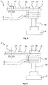
- Fig. 3 shows a schematic view and Fig. 4 shows a schematic side view of the control board 14 comprising the current measuring arrangement 7 which is arranged on the load conductor 9.
- the load conductor 9 is divided into a board piece 9a and into a supply cable 9b by a connection socket 16.
- the current measuring arrangement 7 has a measuring unit 17 which evaluates and passes on measurement data which is detected by the Hall sensor 8.
- the measuring unit 17 is electrically connected to the board piece 9a of the load conductor 9, and the Hall sensor 8 is arranged on the measuring unit 17 so as to have an electromagnetic effect.
- the Hall sensor 8 detects the current which flows through the measuring unit 17 which is connected into the second voltage supply system 2b.
- the Hall sensor 8 is supplied by the first voltage supply system 2a and is connected to the measuring unit 17 only in a signal-transmitting manner.
- Fig. 5 shows a schematic side view of the control board 14, wherein the Hall sensor 8 is arranged on the connection socket 16 of the load conductor 9 so as to have an electromagnetic effect.
- the Hall sensor 8 is secured directly to the control board 14, wherein the Hall sensor 8 is nevertheless arranged in an electromagnetic field which is generated around the connection socket 16.
- Fig. 6 shows a schematic side view of the control board 14 comprising the Hall sensor 8 and comprising an iron core 18.
- the iron core 18 is arranged on the Hall sensor 8 in such a way that the electromagnetic effect of the Hall sensor 8 with the load conductor 9 is amplified. Owing to the iron core 18, the electromagnetic field around the load conductor 9 is amplified and the Hall sensor 8 can also accurately detect relatively low currents.
- the iron core 18 is of substantially annular design and is arranged around the connection socket 16 of the load conductor 9. The iron core 18 of annular design can increase the electromagnetic field around the connection socket 16 in a particularly effective manner.
- the on-board motor vehicle electrical system 1 allows standard-conforming DC-isolation of the first voltage supply system 2a and of the second voltage supply system 2b from one another and accurate and DC-isolated detection of the current flowing across the load 6. This advantageously allows more accurate driving of the load 6 and minimizes the risk of a short circuit.
Landscapes
- Physics & Mathematics (AREA)
- General Physics & Mathematics (AREA)
- Engineering & Computer Science (AREA)
- Mechanical Engineering (AREA)
- Electromagnetism (AREA)
- Measuring Instrument Details And Bridges, And Automatic Balancing Devices (AREA)
Priority Applications (2)
| Application Number | Priority Date | Filing Date | Title |
|---|---|---|---|
| EP17171464.5A EP3403886B1 (fr) | 2017-05-17 | 2017-05-17 | Système électrique de véhicule automobile embarqué |
| CN201810419482.2A CN108957093A (zh) | 2017-05-17 | 2018-05-04 | 车载机动车电气系统 |
Applications Claiming Priority (1)
| Application Number | Priority Date | Filing Date | Title |
|---|---|---|---|
| EP17171464.5A EP3403886B1 (fr) | 2017-05-17 | 2017-05-17 | Système électrique de véhicule automobile embarqué |
Publications (2)
| Publication Number | Publication Date |
|---|---|
| EP3403886A1 true EP3403886A1 (fr) | 2018-11-21 |
| EP3403886B1 EP3403886B1 (fr) | 2019-12-18 |
Family
ID=59034430
Family Applications (1)
| Application Number | Title | Priority Date | Filing Date |
|---|---|---|---|
| EP17171464.5A Active EP3403886B1 (fr) | 2017-05-17 | 2017-05-17 | Système électrique de véhicule automobile embarqué |
Country Status (2)
| Country | Link |
|---|---|
| EP (1) | EP3403886B1 (fr) |
| CN (1) | CN108957093A (fr) |
Citations (2)
| Publication number | Priority date | Publication date | Assignee | Title |
|---|---|---|---|---|
| DE102004046275B4 (de) | 2003-09-23 | 2006-12-21 | Saxotec Gmbh & Co.Kg | Vorrichtung zur Überwachung der Temperatur von Hochspannung führenden Baugruppen |
| EP2711248A1 (fr) | 2012-09-20 | 2014-03-26 | Eberspächer catem GmbH & Co. KG | Réseau de bord bitension avec protection contre les surtensions |
Family Cites Families (4)
| Publication number | Priority date | Publication date | Assignee | Title |
|---|---|---|---|---|
| US8508069B2 (en) * | 2010-06-01 | 2013-08-13 | GM Global Technology Operations LLC | Vehicular electrical systems |
| DE102013009801A1 (de) * | 2013-06-12 | 2014-12-18 | Audi Ag | Kraftfahrzeug mit zwei Bordnetzen mit unterschiedlichen Bordnetzspannungen |
| DE102014008516A1 (de) * | 2014-06-07 | 2015-12-17 | Man Truck & Bus Ag | Bordnetz für ein Kraftfahrzeug |
| CN204595058U (zh) * | 2015-05-06 | 2015-08-26 | 赤峰学院 | 非接触式电流测定装置 |
-
2017
- 2017-05-17 EP EP17171464.5A patent/EP3403886B1/fr active Active
-
2018
- 2018-05-04 CN CN201810419482.2A patent/CN108957093A/zh active Pending
Patent Citations (2)
| Publication number | Priority date | Publication date | Assignee | Title |
|---|---|---|---|---|
| DE102004046275B4 (de) | 2003-09-23 | 2006-12-21 | Saxotec Gmbh & Co.Kg | Vorrichtung zur Überwachung der Temperatur von Hochspannung führenden Baugruppen |
| EP2711248A1 (fr) | 2012-09-20 | 2014-03-26 | Eberspächer catem GmbH & Co. KG | Réseau de bord bitension avec protection contre les surtensions |
Also Published As
| Publication number | Publication date |
|---|---|
| EP3403886B1 (fr) | 2019-12-18 |
| CN108957093A (zh) | 2018-12-07 |
Similar Documents
| Publication | Publication Date | Title |
|---|---|---|
| CN104852224B (zh) | 连接器 | |
| US9234922B2 (en) | Measuring system for monitoring at least one phase of a system | |
| TWI485950B (zh) | 消耗電力管理系統 | |
| CN104603631B (zh) | 用于验证电流传感器结果的可信性的方法和装置 | |
| US10985549B2 (en) | Fault current protection device for monitoring an electric load for a vehicle, and method for carrying out a self-test of a fault current sensor | |
| JP5477666B2 (ja) | 直流電圧変成器を保護する装置 | |
| EP3403886B1 (fr) | Système électrique de véhicule automobile embarqué | |
| US20200153316A1 (en) | Electric machine with integrated power electronics | |
| EP3403885B1 (fr) | Système électrique de véhicule automobile embarqué | |
| JP2014119315A (ja) | 電流センサ及び電流センサユニット | |
| JP2016003916A (ja) | 電流検出回路 | |
| KR101332842B1 (ko) | 차량의 쇼트 판단장치 | |
| US11171475B2 (en) | Fault current sensor for a fault current protection device for monitoring an electrical consumer for a vehicle | |
| KR102796549B1 (ko) | 제어 유닛을 구비하는 차량의 액추에이터에서 고장 전류를 검출하기 위한 장치 | |
| US10348224B2 (en) | Motor position sensor device | |
| JP5989171B1 (ja) | 電流検出回路、及びその回路を備えた車両用電子制御装置 | |
| ATE460678T1 (de) | Elektrisches versorgungsnetzwerk mit kurzschluss- und unterbrechungsdetektion für bordnetze von kraftfahrzeugen | |
| EP0898173B1 (fr) | Dispositif pour détecter des fautes dans un conducteur électrique d'un véhicule, en particulier un véhicule commercial | |
| CN109283376B (zh) | 具有至少一个待冷却的部件的电子装置 | |
| EP3405000A1 (fr) | Chauffage pour un véhicule à moteur | |
| US20230417844A1 (en) | Disconnection detection device and control device | |
| CN106979826B (zh) | 传感器模块,电机,功率电子设备和车辆 | |
| EP2963426B1 (fr) | Dispositif de mesure pour mesurer un courant continu et alternatif | |
| US20120007629A1 (en) | Method For Detecting A Short-Circuit, And Power Supply Module Implementing Said Method | |
| KR200342993Y1 (ko) | 차단기 동작코일의 단선유무 감지회로 |
Legal Events
| Date | Code | Title | Description |
|---|---|---|---|
| PUAI | Public reference made under article 153(3) epc to a published international application that has entered the european phase |
Free format text: ORIGINAL CODE: 0009012 |
|
| STAA | Information on the status of an ep patent application or granted ep patent |
Free format text: STATUS: THE APPLICATION HAS BEEN PUBLISHED |
|
| AK | Designated contracting states |
Kind code of ref document: A1 Designated state(s): AL AT BE BG CH CY CZ DE DK EE ES FI FR GB GR HR HU IE IS IT LI LT LU LV MC MK MT NL NO PL PT RO RS SE SI SK SM TR |
|
| AX | Request for extension of the european patent |
Extension state: BA ME |
|
| STAA | Information on the status of an ep patent application or granted ep patent |
Free format text: STATUS: REQUEST FOR EXAMINATION WAS MADE |
|
| 17P | Request for examination filed |
Effective date: 20190410 |
|
| RBV | Designated contracting states (corrected) |
Designated state(s): AL AT BE BG CH CY CZ DE DK EE ES FI FR GB GR HR HU IE IS IT LI LT LU LV MC MK MT NL NO PL PT RO RS SE SI SK SM TR |
|
| GRAP | Despatch of communication of intention to grant a patent |
Free format text: ORIGINAL CODE: EPIDOSNIGR1 |
|
| STAA | Information on the status of an ep patent application or granted ep patent |
Free format text: STATUS: GRANT OF PATENT IS INTENDED |
|
| RIC1 | Information provided on ipc code assigned before grant |
Ipc: B60R 16/03 20060101AFI20190709BHEP |
|
| INTG | Intention to grant announced |
Effective date: 20190801 |
|
| GRAS | Grant fee paid |
Free format text: ORIGINAL CODE: EPIDOSNIGR3 |
|
| GRAA | (expected) grant |
Free format text: ORIGINAL CODE: 0009210 |
|
| STAA | Information on the status of an ep patent application or granted ep patent |
Free format text: STATUS: THE PATENT HAS BEEN GRANTED |
|
| AK | Designated contracting states |
Kind code of ref document: B1 Designated state(s): AL AT BE BG CH CY CZ DE DK EE ES FI FR GB GR HR HU IE IS IT LI LT LU LV MC MK MT NL NO PL PT RO RS SE SI SK SM TR |
|
| REG | Reference to a national code |
Ref country code: CH Ref legal event code: EP |
|
| REG | Reference to a national code |
Ref country code: IE Ref legal event code: FG4D |
|
| REG | Reference to a national code |
Ref country code: DE Ref legal event code: R096 Ref document number: 602017009752 Country of ref document: DE |
|
| REG | Reference to a national code |
Ref country code: AT Ref legal event code: REF Ref document number: 1214253 Country of ref document: AT Kind code of ref document: T Effective date: 20200115 |
|
| REG | Reference to a national code |
Ref country code: NL Ref legal event code: MP Effective date: 20191218 |
|
| PG25 | Lapsed in a contracting state [announced via postgrant information from national office to epo] |
Ref country code: LT Free format text: LAPSE BECAUSE OF FAILURE TO SUBMIT A TRANSLATION OF THE DESCRIPTION OR TO PAY THE FEE WITHIN THE PRESCRIBED TIME-LIMIT Effective date: 20191218 Ref country code: BG Free format text: LAPSE BECAUSE OF FAILURE TO SUBMIT A TRANSLATION OF THE DESCRIPTION OR TO PAY THE FEE WITHIN THE PRESCRIBED TIME-LIMIT Effective date: 20200318 Ref country code: GR Free format text: LAPSE BECAUSE OF FAILURE TO SUBMIT A TRANSLATION OF THE DESCRIPTION OR TO PAY THE FEE WITHIN THE PRESCRIBED TIME-LIMIT Effective date: 20200319 Ref country code: NO Free format text: LAPSE BECAUSE OF FAILURE TO SUBMIT A TRANSLATION OF THE DESCRIPTION OR TO PAY THE FEE WITHIN THE PRESCRIBED TIME-LIMIT Effective date: 20200318 Ref country code: SE Free format text: LAPSE BECAUSE OF FAILURE TO SUBMIT A TRANSLATION OF THE DESCRIPTION OR TO PAY THE FEE WITHIN THE PRESCRIBED TIME-LIMIT Effective date: 20191218 Ref country code: LV Free format text: LAPSE BECAUSE OF FAILURE TO SUBMIT A TRANSLATION OF THE DESCRIPTION OR TO PAY THE FEE WITHIN THE PRESCRIBED TIME-LIMIT Effective date: 20191218 Ref country code: FI Free format text: LAPSE BECAUSE OF FAILURE TO SUBMIT A TRANSLATION OF THE DESCRIPTION OR TO PAY THE FEE WITHIN THE PRESCRIBED TIME-LIMIT Effective date: 20191218 |
|
| REG | Reference to a national code |
Ref country code: LT Ref legal event code: MG4D |
|
| PG25 | Lapsed in a contracting state [announced via postgrant information from national office to epo] |
Ref country code: RS Free format text: LAPSE BECAUSE OF FAILURE TO SUBMIT A TRANSLATION OF THE DESCRIPTION OR TO PAY THE FEE WITHIN THE PRESCRIBED TIME-LIMIT Effective date: 20191218 Ref country code: HR Free format text: LAPSE BECAUSE OF FAILURE TO SUBMIT A TRANSLATION OF THE DESCRIPTION OR TO PAY THE FEE WITHIN THE PRESCRIBED TIME-LIMIT Effective date: 20191218 |
|
| PG25 | Lapsed in a contracting state [announced via postgrant information from national office to epo] |
Ref country code: AL Free format text: LAPSE BECAUSE OF FAILURE TO SUBMIT A TRANSLATION OF THE DESCRIPTION OR TO PAY THE FEE WITHIN THE PRESCRIBED TIME-LIMIT Effective date: 20191218 |
|
| PG25 | Lapsed in a contracting state [announced via postgrant information from national office to epo] |
Ref country code: CZ Free format text: LAPSE BECAUSE OF FAILURE TO SUBMIT A TRANSLATION OF THE DESCRIPTION OR TO PAY THE FEE WITHIN THE PRESCRIBED TIME-LIMIT Effective date: 20191218 Ref country code: EE Free format text: LAPSE BECAUSE OF FAILURE TO SUBMIT A TRANSLATION OF THE DESCRIPTION OR TO PAY THE FEE WITHIN THE PRESCRIBED TIME-LIMIT Effective date: 20191218 Ref country code: NL Free format text: LAPSE BECAUSE OF FAILURE TO SUBMIT A TRANSLATION OF THE DESCRIPTION OR TO PAY THE FEE WITHIN THE PRESCRIBED TIME-LIMIT Effective date: 20191218 Ref country code: PT Free format text: LAPSE BECAUSE OF FAILURE TO SUBMIT A TRANSLATION OF THE DESCRIPTION OR TO PAY THE FEE WITHIN THE PRESCRIBED TIME-LIMIT Effective date: 20200513 Ref country code: RO Free format text: LAPSE BECAUSE OF FAILURE TO SUBMIT A TRANSLATION OF THE DESCRIPTION OR TO PAY THE FEE WITHIN THE PRESCRIBED TIME-LIMIT Effective date: 20191218 |
|
| PG25 | Lapsed in a contracting state [announced via postgrant information from national office to epo] |
Ref country code: SM Free format text: LAPSE BECAUSE OF FAILURE TO SUBMIT A TRANSLATION OF THE DESCRIPTION OR TO PAY THE FEE WITHIN THE PRESCRIBED TIME-LIMIT Effective date: 20191218 Ref country code: IS Free format text: LAPSE BECAUSE OF FAILURE TO SUBMIT A TRANSLATION OF THE DESCRIPTION OR TO PAY THE FEE WITHIN THE PRESCRIBED TIME-LIMIT Effective date: 20200418 Ref country code: SK Free format text: LAPSE BECAUSE OF FAILURE TO SUBMIT A TRANSLATION OF THE DESCRIPTION OR TO PAY THE FEE WITHIN THE PRESCRIBED TIME-LIMIT Effective date: 20191218 |
|
| REG | Reference to a national code |
Ref country code: DE Ref legal event code: R097 Ref document number: 602017009752 Country of ref document: DE |
|
| REG | Reference to a national code |
Ref country code: AT Ref legal event code: MK05 Ref document number: 1214253 Country of ref document: AT Kind code of ref document: T Effective date: 20191218 |
|
| PLBE | No opposition filed within time limit |
Free format text: ORIGINAL CODE: 0009261 |
|
| STAA | Information on the status of an ep patent application or granted ep patent |
Free format text: STATUS: NO OPPOSITION FILED WITHIN TIME LIMIT |
|
| PG25 | Lapsed in a contracting state [announced via postgrant information from national office to epo] |
Ref country code: ES Free format text: LAPSE BECAUSE OF FAILURE TO SUBMIT A TRANSLATION OF THE DESCRIPTION OR TO PAY THE FEE WITHIN THE PRESCRIBED TIME-LIMIT Effective date: 20191218 Ref country code: DK Free format text: LAPSE BECAUSE OF FAILURE TO SUBMIT A TRANSLATION OF THE DESCRIPTION OR TO PAY THE FEE WITHIN THE PRESCRIBED TIME-LIMIT Effective date: 20191218 |
|
| 26N | No opposition filed |
Effective date: 20200921 |
|
| PG25 | Lapsed in a contracting state [announced via postgrant information from national office to epo] |
Ref country code: SI Free format text: LAPSE BECAUSE OF FAILURE TO SUBMIT A TRANSLATION OF THE DESCRIPTION OR TO PAY THE FEE WITHIN THE PRESCRIBED TIME-LIMIT Effective date: 20191218 Ref country code: AT Free format text: LAPSE BECAUSE OF FAILURE TO SUBMIT A TRANSLATION OF THE DESCRIPTION OR TO PAY THE FEE WITHIN THE PRESCRIBED TIME-LIMIT Effective date: 20191218 |
|
| PG25 | Lapsed in a contracting state [announced via postgrant information from national office to epo] |
Ref country code: LI Free format text: LAPSE BECAUSE OF NON-PAYMENT OF DUE FEES Effective date: 20200531 Ref country code: MC Free format text: LAPSE BECAUSE OF FAILURE TO SUBMIT A TRANSLATION OF THE DESCRIPTION OR TO PAY THE FEE WITHIN THE PRESCRIBED TIME-LIMIT Effective date: 20191218 Ref country code: IT Free format text: LAPSE BECAUSE OF FAILURE TO SUBMIT A TRANSLATION OF THE DESCRIPTION OR TO PAY THE FEE WITHIN THE PRESCRIBED TIME-LIMIT Effective date: 20191218 Ref country code: CH Free format text: LAPSE BECAUSE OF NON-PAYMENT OF DUE FEES Effective date: 20200531 |
|
| PG25 | Lapsed in a contracting state [announced via postgrant information from national office to epo] |
Ref country code: PL Free format text: LAPSE BECAUSE OF FAILURE TO SUBMIT A TRANSLATION OF THE DESCRIPTION OR TO PAY THE FEE WITHIN THE PRESCRIBED TIME-LIMIT Effective date: 20191218 |
|
| REG | Reference to a national code |
Ref country code: BE Ref legal event code: MM Effective date: 20200531 |
|
| PG25 | Lapsed in a contracting state [announced via postgrant information from national office to epo] |
Ref country code: LU Free format text: LAPSE BECAUSE OF NON-PAYMENT OF DUE FEES Effective date: 20200517 |
|
| PG25 | Lapsed in a contracting state [announced via postgrant information from national office to epo] |
Ref country code: FR Free format text: LAPSE BECAUSE OF NON-PAYMENT OF DUE FEES Effective date: 20200531 Ref country code: IE Free format text: LAPSE BECAUSE OF NON-PAYMENT OF DUE FEES Effective date: 20200517 |
|
| PG25 | Lapsed in a contracting state [announced via postgrant information from national office to epo] |
Ref country code: BE Free format text: LAPSE BECAUSE OF NON-PAYMENT OF DUE FEES Effective date: 20200531 |
|
| GBPC | Gb: european patent ceased through non-payment of renewal fee |
Effective date: 20210517 |
|
| PG25 | Lapsed in a contracting state [announced via postgrant information from national office to epo] |
Ref country code: GB Free format text: LAPSE BECAUSE OF NON-PAYMENT OF DUE FEES Effective date: 20210517 |
|
| PG25 | Lapsed in a contracting state [announced via postgrant information from national office to epo] |
Ref country code: TR Free format text: LAPSE BECAUSE OF FAILURE TO SUBMIT A TRANSLATION OF THE DESCRIPTION OR TO PAY THE FEE WITHIN THE PRESCRIBED TIME-LIMIT Effective date: 20191218 Ref country code: MT Free format text: LAPSE BECAUSE OF FAILURE TO SUBMIT A TRANSLATION OF THE DESCRIPTION OR TO PAY THE FEE WITHIN THE PRESCRIBED TIME-LIMIT Effective date: 20191218 Ref country code: CY Free format text: LAPSE BECAUSE OF FAILURE TO SUBMIT A TRANSLATION OF THE DESCRIPTION OR TO PAY THE FEE WITHIN THE PRESCRIBED TIME-LIMIT Effective date: 20191218 |
|
| PG25 | Lapsed in a contracting state [announced via postgrant information from national office to epo] |
Ref country code: MK Free format text: LAPSE BECAUSE OF FAILURE TO SUBMIT A TRANSLATION OF THE DESCRIPTION OR TO PAY THE FEE WITHIN THE PRESCRIBED TIME-LIMIT Effective date: 20191218 |
|
| P01 | Opt-out of the competence of the unified patent court (upc) registered |
Effective date: 20240527 |
|
| PGFP | Annual fee paid to national office [announced via postgrant information from national office to epo] |
Ref country code: DE Payment date: 20250521 Year of fee payment: 9 |