EP3403888B1 - Dispositif de rideau gonflable de sécurité et structure pour le montage sur véhicule - Google Patents
Dispositif de rideau gonflable de sécurité et structure pour le montage sur véhicule Download PDFInfo
- Publication number
- EP3403888B1 EP3403888B1 EP16885038.6A EP16885038A EP3403888B1 EP 3403888 B1 EP3403888 B1 EP 3403888B1 EP 16885038 A EP16885038 A EP 16885038A EP 3403888 B1 EP3403888 B1 EP 3403888B1
- Authority
- EP
- European Patent Office
- Prior art keywords
- airbag
- folded
- cover cloth
- vehicle
- back part
- Prior art date
- Legal status (The legal status is an assumption and is not a legal conclusion. Google has not performed a legal analysis and makes no representation as to the accuracy of the status listed.)
- Active
Links
Images


Classifications
-
- B—PERFORMING OPERATIONS; TRANSPORTING
- B60—VEHICLES IN GENERAL
- B60R—VEHICLES, VEHICLE FITTINGS, OR VEHICLE PARTS, NOT OTHERWISE PROVIDED FOR
- B60R21/00—Arrangements or fittings on vehicles for protecting or preventing injuries to occupants or pedestrians in case of accidents or other traffic risks
- B60R21/02—Occupant safety arrangements or fittings, e.g. crash pads
- B60R21/16—Inflatable occupant restraints or confinements designed to inflate upon impact or impending impact, e.g. air bags
- B60R21/23—Inflatable members
- B60R21/231—Inflatable members characterised by their shape, construction or spatial configuration
- B60R21/232—Curtain-type airbags deploying mainly in a vertical direction from their top edge
-
- B—PERFORMING OPERATIONS; TRANSPORTING
- B60—VEHICLES IN GENERAL
- B60R—VEHICLES, VEHICLE FITTINGS, OR VEHICLE PARTS, NOT OTHERWISE PROVIDED FOR
- B60R21/00—Arrangements or fittings on vehicles for protecting or preventing injuries to occupants or pedestrians in case of accidents or other traffic risks
- B60R21/02—Occupant safety arrangements or fittings, e.g. crash pads
- B60R21/16—Inflatable occupant restraints or confinements designed to inflate upon impact or impending impact, e.g. air bags
- B60R21/20—Arrangements for storing inflatable members in their non-use or deflated condition; Arrangement or mounting of air bag modules or components
- B60R21/213—Arrangements for storing inflatable members in their non-use or deflated condition; Arrangement or mounting of air bag modules or components in vehicle roof frames or pillars
-
- B—PERFORMING OPERATIONS; TRANSPORTING
- B60—VEHICLES IN GENERAL
- B60R—VEHICLES, VEHICLE FITTINGS, OR VEHICLE PARTS, NOT OTHERWISE PROVIDED FOR
- B60R21/00—Arrangements or fittings on vehicles for protecting or preventing injuries to occupants or pedestrians in case of accidents or other traffic risks
- B60R21/02—Occupant safety arrangements or fittings, e.g. crash pads
- B60R21/16—Inflatable occupant restraints or confinements designed to inflate upon impact or impending impact, e.g. air bags
- B60R21/23—Inflatable members
- B60R21/237—Inflatable members characterised by the way they are folded
-
- B—PERFORMING OPERATIONS; TRANSPORTING
- B60—VEHICLES IN GENERAL
- B60R—VEHICLES, VEHICLE FITTINGS, OR VEHICLE PARTS, NOT OTHERWISE PROVIDED FOR
- B60R21/00—Arrangements or fittings on vehicles for protecting or preventing injuries to occupants or pedestrians in case of accidents or other traffic risks
- B60R21/02—Occupant safety arrangements or fittings, e.g. crash pads
- B60R21/16—Inflatable occupant restraints or confinements designed to inflate upon impact or impending impact, e.g. air bags
- B60R21/20—Arrangements for storing inflatable members in their non-use or deflated condition; Arrangement or mounting of air bag modules or components
- B60R21/201—Packaging straps or envelopes for inflatable members
-
- B—PERFORMING OPERATIONS; TRANSPORTING
- B60—VEHICLES IN GENERAL
- B60R—VEHICLES, VEHICLE FITTINGS, OR VEHICLE PARTS, NOT OTHERWISE PROVIDED FOR
- B60R21/00—Arrangements or fittings on vehicles for protecting or preventing injuries to occupants or pedestrians in case of accidents or other traffic risks
- B60R21/02—Occupant safety arrangements or fittings, e.g. crash pads
- B60R21/16—Inflatable occupant restraints or confinements designed to inflate upon impact or impending impact, e.g. air bags
- B60R21/23—Inflatable members
- B60R21/231—Inflatable members characterised by their shape, construction or spatial configuration
- B60R21/2334—Expansion control features
- B60R21/2346—Soft diffusers
-
- B—PERFORMING OPERATIONS; TRANSPORTING
- B60—VEHICLES IN GENERAL
- B60R—VEHICLES, VEHICLE FITTINGS, OR VEHICLE PARTS, NOT OTHERWISE PROVIDED FOR
- B60R21/00—Arrangements or fittings on vehicles for protecting or preventing injuries to occupants or pedestrians in case of accidents or other traffic risks
- B60R21/02—Occupant safety arrangements or fittings, e.g. crash pads
- B60R21/16—Inflatable occupant restraints or confinements designed to inflate upon impact or impending impact, e.g. air bags
- B60R2021/161—Inflatable occupant restraints or confinements designed to inflate upon impact or impending impact, e.g. air bags characterised by additional means for controlling deployment trajectory
Definitions
- the present invention relates to a curtain airbag device in which an airbag is deployed in a curtain-like manner along a side window in a side collision or a rollover so as to protect an occupant's head and prevent the occupant from being thrown out to the outside of a vehicle, and a mounting structure of such device on the vehicle. Specifically, it is prevented that an edge of a pillar trim covering (a pillar garnish) is broken and scattered when the airbag is deployed.
- the terms “above” and “up” denote a ceiling side of a motor vehicle
- the terms “below” and “down” denote a floor side of the motor vehicle.
- the terms “front” and “forward” denote a forward direction side of the motor vehicle
- the terms “rear” and “backward” denote a retreating direction side of the motor vehicle.
- a curtain airbag device When a high load is applied on a side of a motor vehicle in a side collision or a rollover, a curtain airbag device causes an inflator to be operated so as to generate a gas and deploys an airbag in a vehicle compartment in the curtain-like manner in a vertically lower direction along the side window.
- such curtain airbag device 1 is mounted by using clips 2 and brackets 3, for instance, from a roof side rail RSR toward a front pillar FP.
- the curtain airbag device 1 in the mounting state explained above is covered by a front pillar trim covering and a room head lining (a roof trim covering) inside the vehicle compartment, and is stored at the outside of the vehicle compartment with respect to these trim coverings.
- an airbag 5 that is wound in, for instance, a roll state, is deployed by the gas that is generated by an inflator 4.
- the front pillar trim covering and the room head lining are pushed toward an inside of the vehicle compartment and are disengaged from the front pillar FP and the roof side rail RSR of a vehicle body.
- edges being disengaged from the front pillar trim covering and the room head lining are pushed and expanded toward the inside of the vehicle compartment so that the airbag is deployed in the curtain-like manner in the vehicle compartment from such opening that is formed by being pushed and expanded.
- Patent Document 1 Japanese Patent Publication Number 2014-65329 .
- Patent document 2 GB 2 440 672 discloses a curtain airbag device according to the preamble of claim 1 and/or 2.
- a problem that is solved by the present invention is that there is a possibility that when the airbag is deployed in a state in which the airbag is caught inside of a trim covering, in particular, a front pillar trim covering and a rear pillar trim covering, the trim coverings are damaged.
- An object of the present invention is to prevent edges of trim coverings, in particular, a front pillar trim covering and a rear pillar trim covering from being cracked and scattered at the time of deploying an airbag.
- the present invention relates to a curtain airbag device having an airbag that is mountable along a roof side rail of a vehicle in a vehicle longitudinal direction of the vehicle so as to configured to be stored in the vehicle and that is deployed in a curtain-like manner along a side window in a vehicle compartment by a gas generated by an inflator in case of emergency.
- the present invention includes the following most essential features: the airbag which is folded has a cover cloth that is wound to cover at least part of an outer circumference of the airbag that extends in a longitudinal direction of the airbag; the cover cloth has a first folded-back part that is configured by folding back one end of the cover cloth in a circumferential direction of the outer circumference of a cross section, which is perpendicular to the longitudinal direction, of the folded airbag; and an edge of the outer circumference of the folded airbag is held between the first folded-back part and the other end of the cover cloth.
- the first folded-back part is inserted into a folding gap of the folded airbag from an edge of the outer circumference of the folded airbag.
- the airbag that is wound in the roll state there is a second folded-back part that is configured by folding back an edge of the outer circumference of the airbag in a direction opposite to a winding direction to cover part of the outer circumference of the airbag.
- the first folded-back part of the cover cloth is inserted into a gap between a main body of the airbag that is wound in the roll state and the second folded-back part.
- the cover cloth is thicker or harder than a base fabric that forms the airbag.
- the cover cloth has a proper hardness, at the time of deploying the airbag, a cushion base fabric is hardly caught at an edge of the trim covering so that the airbag is smoothly deployed. Further, the damage to the edge of the trim covering is reduced and the cracking of the trim covering itself can also be prevented.
- the hardness of the cloth is measured by measuring the bending resistance according to a cantilever method (Standards: ISO9073-7, ASTM D-5732, GB/T18318-2001, JIS L-1906, JIS L-1912, JIS L-1913, JIS L-1096, and JIS L-1018).
- the bending resistance indicates a hardness and a softness when a cloth is bent and can be measured by a cantilever tester.
- the cantilever tester has a tilted surface at angle of 45 degrees in regard to a general woven fabric and at angle of 41.5 degrees in regard to a nonwoven fabric and has a smooth flat surface which is horizontal at the time of the installation of the tester and is continuously provided with the tilted surface at an upper edge of the tilted surface.
- a cloth as a test piece is placed in a manner in which one end of the cloth aligns with a boundary between the flat surface and the tilted surface, the cloth, which is pressed by a flat metal plate from above, gently slides toward the tilted surface, and a scale (a length) is read when a center of the end of the test piece contacts the slope.
- the bending resistance is indicated by the length of the cloth that is extruded and it is shown that the longer length is the harder cloth.
- a webbing that is used for a vehicle seat belt has a high bending resistance (a measured value is long) and hard, therefore, it is in a preferable state.
- the thicker fabric has the higher bending resistance (the measured value is long) and hard, therefore, it is in a preferable state.
- a mounting structure of the curtain airbag device on a vehicle according to the present invention when the airbag is mounted on the roof side rail and a pillar of the vehicle by using a tab that is attached to a base fabric of the airbag so that the airbag extends in a vehicle longitudinal direction, the airbag is mounted by using the tab that is integrally attached to the cover cloth and the base fabric of the airbag at a mounting position of the cover cloth.
- the above configuration is the mounting structure of the curtain airbag device on the vehicle according to the present invention.
- the pillar in the mounting structure of the curtain airbag device on the vehicle according to the present invention is a front pillar and/or a rear pillar.
- the cover cloth is overlapped with an edge of a roof trim covering side of a pillar trim covering of the pillar.
- the cover cloth is disposed at a seam between the pillar trim covering and a roof trim covering.
- a direct damage that is affected to the edge of the trim covering can be reduced so that the cracking of the trim covering can be prevented.
- the first folded-back part that is provided at one end of the cover cloth in a circumferential direction of the outer circumference of a cross section, which is perpendicular to the longitudinal direction, of the folded airbag and the other end of the cover cloth sandwich an edge of the outer circumference of the folded airbag.
- the first folded-back part of the cover cloth is inserted into a folding gap of the folded airbag from the edge of the outer circumference of the folded airbag.
- the airbag is smoothly deployed in the expected deployment direction so that the edges of the front pillar trim covering and the rear pillar trim covering are not cracked and scattered.
- the first folded-back part that is provided at one end of the cover cloth in the circumferential direction of the outer circumference of the cross section, which is perpendicular to the longitudinal direction, of the folded airbag and the other end of the cover cloth sandwich the edge of the outer circumference of the folded airbag.
- the first folded-back part of the cover cloth is inserted into the folding gap of the folded airbag from the edge of the outer circumference of the folded airbag.
- the cover cloth can be certainly released, without a deterioration of the deployment performance of the airbag.
- the cover cloth extrudes the trim covering and covers the edge of the trim covering at an outlet (an opening) of the airbag.
- the cover cloth prevents the bag from being caught at the edge of the trim covering and helps the smooth deployment of the airbag. Therefore, because the edges of the front pillar trim covering and the rear pillar trim covering are not cracked and scattered, the safety of the occupants can be secured.
- An object of the present invention is to prevent edges of trim coverings, in particular, a front pillar trim covering and a rear pillar trim covering from being cracked and scattered at the time of deploying an airbag.
- the object can be achieved by sandwiching an edge of an outer circumference of a folded airbag between a first folded-back part that is provided at one end of a cover cloth and the other end side.
- the object can be achieved by inserting the first folded-back part of the cover cloth into a folding gap of the folded airbag from the edge of the outer circumference of the folded airbag so as to cover the outer circumference of the airbag.
- a curtain airbag device and a mounting structure of the curtain airbag device on a vehicle according to a first aspect of the present invention will be explained below with reference to Figs. 1 - 5 .
- a curtain airbag device 1 has an airbag 5 that is deployed in a curtain-like manner along a side window 6 (refer to Fig. 9 ) by a gas being ejected from an inflator 4 (refer to Fig. 9 ). Further, because of the deployment of the airbag 5, a seated occupant's head is protected, and at the same time, an occupant is prevented from being thrown out to the outside of a vehicle.
- the airbag 5 is formed in a long state that is provided by being wound in, for instance, a roll state in a substantially up and down direction. Further, a body member 5a that is wound in the roll state has a second folded-back part 5b at an edge of an outer circumference of the body member 5a, and the second folded-back part 5b, which is folded back in an direction opposite to a winding direction of the body member 5a, covers a part of the outer circumference of the body member 5a.
- a reference numeral 7 is a cover cloth that is provided at a part corresponding to a front pillar FP (refer to Fig. 9 ) of the airbag 5, which is wound in the roll state and in the long state.
- the cover cloth 7 is made by, for example, a webbing that is used for a vehicle seat belt, and alternatively made by a thick cloth that is thicker than a base fabric 5d that forms the airbag 5.
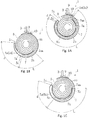
- the cover cloth 7 has a length (refer to Fig. 3 ) that makes it possible to round around the outer circumference of the body member 5a of the airbag 5 that is wound in the roll state and has a first folded-back part 7a that is obtained by folding back one end side in a circumferential direction of the outer circumference of a cross section which is perpendicular to a longitudinal direction of the airbag 5. Further, the first folded-back part 7a is inserted between the body member 5a and the second folded-back part 5b from a folded-back position 5c of the second folded-back part 5b of the airbag 5.
- An insertion length L of the first folded-back part 7a of the cover cloth 7 and a distance d between a folded-back position 7c of the cover cloth 7 and the folded-back position 5c of the airbag 5 are not particularly limited so along as they are within the ranges shown in Figs. 1A - 1C .
- Fig. 1A shows a state in which the insertion length L of the first folded-back part 7a of the cover cloth 7 is maximum and the distance d between the folded-back position 7c of the cover cloth 7 and the folded-back position 5c of the airbag 5 is minimum.
- Fig. 1B shows a state in which the insertion length L of the first folded-back part 7a of the cover cloth 7 is minimum and the distance d between the folded-back position 7c of the cover cloth 7 and the folded-back position 5c of the airbag 5 is maximum.
- Fig. 1C shows a state in which the insertion length L of the first folded-back part 7a of the cover cloth 7 and the distance d between the folded-back position 7c of the cover cloth 7 and the folded-back position 5c of the airbag 5 are at the intermediate level between Figs. 1A and 1B .
- a tab 9 is sewn together with the base fabric 5d and the cover cloth 7 at, for instance, a center of the cover cloth 7 that is attached to the base fabric 5d in the longitudinal direction (refer to Fig. 3 ).
- a reference numeral 10 corresponds to a sewing part in which the base fabric 5d, the cover cloth 7, and a tab 9 are integrally sewn and a reference numeral 5aa corresponds to an upper edge of the body member 5a that is wound in the roll state of the airbag 5.
- the curtain airbag device 1 is mounted, by using the tab 9 that is attached to the base fabric 5d that is located at the upper end of the airbag 5, along with the inflator 4 on, for instance, the front pillar FP and the roof side rail RSR of the compartment so as to extend in a vehicle longitudinal direction of the vehicle (refer to Fig. 9 ). At that time, it is mounted on the front pillar FP by using a bracket 3 that is attached to the tab 9 at an attaching position of the cover cloth 7.
- a part of the cover cloth 7 is provided so as to overlap with an end part of a front pillar trim covering FPG on a side of a roof trim covering RG (refer to Fig. 4C ).
- the entirety of the cover cloth 7 is overlapped with the end part of the front pillar trim covering FPG on the side of the roof trim covering RG.
- the cover cloth 7 is much softer and easily deformed than the trim covering, the cover cloth 7 smoothly covers a lower end of the front pillar trim covering FPG when the front pillar trim covering FPG is pushed to open. Therefore, the cover cloth 7 is deployed so as to extend from the lower end of the front pillar trim covering FPG and helps the smooth deployment of the airbag 5.
- the cover cloth 7 may also be provided so as to span a seam S between the front pillar trim covering FPG and the roof trim covering RG on the side of the roof side rail.
- the cover cloth 7 When the cover cloth 7 is provided so as to span the seam S, the cover cloth 7 smoothly covers an opening lower end part of the seam between the front pillar trim covering FPG and the roof trim covering RG that open differently at the time of deploying the airbag 5. Therefore, because a level difference at a position of the opening lower end part is eliminated, it becomes possible to prevent the airbag 5 from being caught.
- the gas which is ejected from the inflator 4 by receiving a signal from a sensor, is supplied to a chamber via a duct so that the airbag 5 is deployed in the curtain-like manner.
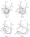
- the second folded-back part 5b is deployed beginning of a storage state shown in Fig. 2A and then continuing of states shown in Figs. 2B to 2D in such order. Because of the deployment of the second folded-back part 5b, the first folded-back part 7a of the cover cloth 7 that is inserted between the body member 5a and the second folded-back part 5b of the airbag 5 can be certainly released.
- Fig. 2A shows the state in which the airbag 5 is stored inside the front pillar FP.
- an opening 0 that is formed between the front pillar FP and the front pillar trim covering FPG is pushed and expanded. Even when the opening 0 is expanded, an area adjacent to the lower end of the cover cloth 7 still remains in the opening because of further extending in a direction toward the front pillar from the lower end part of the front pillar trim covering FPG ( Fig. 2C ).
- an end part 7aa of the first folded-back part 7a of the cover cloth 7 downwardly hangs down and deforms so as to eliminate a protrusion of the lower end part of the front pillar trim covering FPG. Therefore, because the airbag 5 is not caught by the lower end part of the front pillar trim covering FPG, the deployment is smoothly performed.
- the airbag 5 is deployed in the expected deployment direction and the edge of the front pillar trim covering FPG is not cracked and scattered.
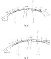
- the airbag 5 can be adopted that the second folded-back part 5b is not provided as shown in Fig. 7A .
- the damage prevention for the front pillar trim covering FPG is explained.
- the damage of a rear pillar trim covering at the time of deploying the airbag 5 can be prevented as well by adopting the same configuration.
- the cover cloth 7 which is made by the fabric that is thicker than the base fabric 5d forming the airbag 5 or with the harder fabric such as a webbing, is explained.
- any material that is harder than the base fabric 5d forming the airbag 5 and at the same time that is softer than the trim covering can be used.
Landscapes
- Engineering & Computer Science (AREA)
- Mechanical Engineering (AREA)
- Air Bags (AREA)
- Physics & Mathematics (AREA)
- Fluid Mechanics (AREA)
Claims (10)
- Dispositif de coussin de sécurité gonflable de type rideau (1) ayant un coussin de sécurité gonflable (5) qui peut être monté le long d'un brancard de pavillon (RSR) d'un véhicule dans une direction longitudinale du véhicule de façon à être conçu pour être stocké dans le véhicule et qui est conçu pour être déployé à la manière d'un rideau le long d'une vitre latérale (6) dans un compartiment de véhicule par un gaz généré par un gonfleur (4) en cas d'urgence, le dispositif de coussin de sécurité gonflable de type rideau (1) comprenant :un tissu de recouvrement (7) qui est prévu au niveau du coussin de sécurité gonflable (5) qui est plié, le tissu de recouvrement (7) étant enroulé pour couvrir au moins une partie d'une circonférence externe du coussin de sécurité gonflable (5) qui s'étend dans une direction longitudinale du coussin de sécurité gonflable (5) ; etune première partie repliée (7a) qui est prévue au niveau du tissu de recouvrement (7), la première partie repliée (7a) étant conçue en repliant une extrémité du tissu de recouvrement (7) dans une direction circonférentielle de la circonférence extérieure d'une section transversale, qui est perpendiculaire à la direction longitudinale, du coussin de sécurité gonflable (5) plié, une forme du coussin de sécurité gonflable (5) plié étant conçue en enroulant le coussin de sécurité gonflable (5) dans un état roulé, caractérisé en ce queun bord de la circonférence extérieure du coussin de sécurité gonflable (5) plié est maintenu entre la première partie repliée (7a) et l'autre extrémité du tissu de recouvrement (7), le coussin de sécurité gonflable (5) qui est enroulé à l'état roulé ayant une seconde partie repliée (5b), et la seconde partie repliée (5b) étant conçue en repliant un bord de la circonférence externe du coussin de sécurité gonflable (5) dans une direction opposée à une direction d'enroulement pour recouvrir une partie de la circonférence extérieure du coussin de sécurité gonflable (5), etla première partie repliée (7a) du tissu de recouvrement (7) est insérée dans un espace entre un corps principal du coussin de sécurité gonflable (5) qui est enroulé à l'état roulé et la seconde partie repliée (5b).
- Dispositif de coussin de sécurité gonflable de type rideau (1) ayant un coussin de sécurité gonflable (5) qui peut être monté le long d'un brancard de pavillon (RSR) d'un véhicule dans une direction longitudinale du véhicule de façon à être conçu pour être stocké dans le véhicule et qui est conçu pour être déployé à la manière d'un rideau le long d'une vitre latérale (6) dans un compartiment de véhicule par un gaz généré par un gonfleur (4) en cas d'urgence, le dispositif de coussin de sécurité gonflable de type rideau (1) comprenant :un tissu de recouvrement (7) qui est prévu au niveau du coussin de sécurité gonflable (5) qui est plié, le tissu de recouvrement (7) étant enroulé pour couvrir au moins une partie d'une circonférence externe du coussin de sécurité gonflable (5) qui s'étend dans une direction longitudinale du coussin de sécurité gonflable (5) ; etune première partie repliée (7a) qui est prévue au niveau du tissu de recouvrement (7), la première partie repliée (7a) étant conçue en repliant une extrémité du tissu de recouvrement (7) dans une direction circonférentielle de la circonférence extérieure d'une section transversale, qui est perpendiculaire à la direction longitudinale, du coussin de sécurité gonflable (5) plié, une forme du coussin de sécurité gonflable (5) plié étant conçue en enroulant le coussin de sécurité gonflable (5) dans un état roulé, caractérisé en ce quela première partie repliée (7a) est insérée dans un espace de pliage du coussin de sécurité gonflable (5) plié à partir d'un bord de la circonférence extérieure du coussin de sécurité gonflable (5) plié, le coussin de sécurité gonflable (5) qui est enroulé à l'état roulé ayant une seconde partie repliée (5b), et la seconde partie repliée (5b) étant conçue en repliant un bord de la circonférence externe du coussin de sécurité gonflable (5) dans une direction opposée à une direction d'enroulement pour couvrir une partie de la circonférence extérieure du coussin de sécurité gonflable (5), etla première partie repliée (7a) du tissu de recouvrement (7) est insérée dans un espace entre un corps principal du coussin de sécurité gonflable (5) qui est enroulé à l'état roulé et la seconde partie repliée (5b).
- Dispositif de coussin de sécurité gonflable de type rideau (1) selon l'une des revendications 1 ou 2,
le tissu de recouvrement (7) étant un tissu plus épais qui est plus épais qu'un tissu de base (5d) qui constitue le coussin de sécurité gonflable (5). - Dispositif de coussin de sécurité gonflable de type rideau (1) selon l'une des revendications 1 à 3,
le tissu de recouvrement (7) étant un tissu plus rigide qui est plus rigide qu'un tissu de base (5d) qui constitue le coussin de sécurité gonflable (5). - Structure de montage du dispositif de coussin de sécurité gonflable de type rideau (1) selon l'une des revendications 1 à 4 sur un véhicule, la structure de montage comprenant :
lorsque le coussin de sécurité gonflable (5) est monté sur le brancard de pavillon (RSR) et un montant du véhicule en utilisant une languette (9) qui est fixée à un tissu de base (5d) du coussin de sécurité gonflable (5) de sorte que le coussin de sécurité gonflable (5) s'étend dans la direction longitudinale du véhicule, le coussin de sécurité gonflable (5) étant monté en utilisant la languette (9) qui est fixée de manière solidaire au tissu de recouvrement (7) et au tissu de base (5d) du coussin de sécurité gonflable (5) au niveau d'une position de montage du tissu de recouvrement (7). - Structure de montage selon la revendication 5, le montant étant un montant avant (FP).
- Structure de montage selon la revendication 5, le montant étant un montant arrière (RP).
- Structure de montage selon la revendication 5,
le montant étant constitué d'un montant avant (FP) et d'un montant arrière (RP). - Structure de montage selon l'une des revendications 5 à 8,
au moins une partie du tissu de recouvrement (7) se chevauchant avec un bord d'un côté de revêtement garniture de toit (RG) du brancard de pavillon (RSR) d'une garniture de montant du montant. - Structure de montage selon l'une des revendications 5 à 8,
le tissu de recouvrement (7) étant disposé au niveau d'une couture entre une garniture de montant du montant et un revêtement de garniture de toit (RG) du brancard de pavillon (RSR).
Priority Applications (1)
| Application Number | Priority Date | Filing Date | Title |
|---|---|---|---|
| EP19194683.9A EP3611061B1 (fr) | 2016-01-15 | 2016-11-25 | Dispositif de rideau gonflable de sécurité et structure pour le montage sur véhicule |
Applications Claiming Priority (2)
| Application Number | Priority Date | Filing Date | Title |
|---|---|---|---|
| JP2016006177 | 2016-01-15 | ||
| PCT/JP2016/085057 WO2017122435A1 (fr) | 2016-01-15 | 2016-11-25 | Dispositif de rideau gonflable de sécurité et structure pour le montage sur véhicule |
Related Child Applications (2)
| Application Number | Title | Priority Date | Filing Date |
|---|---|---|---|
| EP19194683.9A Division EP3611061B1 (fr) | 2016-01-15 | 2016-11-25 | Dispositif de rideau gonflable de sécurité et structure pour le montage sur véhicule |
| EP19194683.9A Division-Into EP3611061B1 (fr) | 2016-01-15 | 2016-11-25 | Dispositif de rideau gonflable de sécurité et structure pour le montage sur véhicule |
Publications (3)
| Publication Number | Publication Date |
|---|---|
| EP3403888A1 EP3403888A1 (fr) | 2018-11-21 |
| EP3403888A4 EP3403888A4 (fr) | 2019-06-26 |
| EP3403888B1 true EP3403888B1 (fr) | 2021-06-23 |
Family
ID=59311206
Family Applications (2)
| Application Number | Title | Priority Date | Filing Date |
|---|---|---|---|
| EP19194683.9A Active EP3611061B1 (fr) | 2016-01-15 | 2016-11-25 | Dispositif de rideau gonflable de sécurité et structure pour le montage sur véhicule |
| EP16885038.6A Active EP3403888B1 (fr) | 2016-01-15 | 2016-11-25 | Dispositif de rideau gonflable de sécurité et structure pour le montage sur véhicule |
Family Applications Before (1)
| Application Number | Title | Priority Date | Filing Date |
|---|---|---|---|
| EP19194683.9A Active EP3611061B1 (fr) | 2016-01-15 | 2016-11-25 | Dispositif de rideau gonflable de sécurité et structure pour le montage sur véhicule |
Country Status (5)
| Country | Link |
|---|---|
| US (1) | US10974682B2 (fr) |
| EP (2) | EP3611061B1 (fr) |
| JP (1) | JP6557735B2 (fr) |
| CN (1) | CN108463378B (fr) |
| WO (1) | WO2017122435A1 (fr) |
Families Citing this family (13)
| Publication number | Priority date | Publication date | Assignee | Title |
|---|---|---|---|---|
| CN107428306B (zh) * | 2015-04-13 | 2019-10-29 | 奥托立夫开发公司 | 帘式气囊装置和帘式气囊装置的制造方法 |
| CN107235028B (zh) * | 2016-03-29 | 2021-10-01 | 奥托立夫开发公司 | 安全气囊及安全气囊组件 |
| JP6902111B2 (ja) * | 2017-12-07 | 2021-07-14 | オートリブ ディベロップメント エービー | エアバッグ装置及びその製造方法 |
| US11524652B2 (en) * | 2018-12-20 | 2022-12-13 | Autoliv Development Ab | Curtain airbag and manufacturing method therefor |
| KR102693553B1 (ko) * | 2019-04-12 | 2024-08-08 | 현대모비스 주식회사 | 커튼 에어백 장치 |
| KR102641419B1 (ko) * | 2019-04-12 | 2024-02-27 | 현대모비스 주식회사 | 커튼 에어백 장치 |
| US11285905B2 (en) * | 2019-11-26 | 2022-03-29 | Honda Motor Co., Ltd. | Airbag assembly and method |
| JP2021127005A (ja) * | 2020-02-13 | 2021-09-02 | 豊田合成株式会社 | 頭部保護エアバッグ装置 |
| JP2021146865A (ja) * | 2020-03-18 | 2021-09-27 | 本田技研工業株式会社 | エアバッグ装置 |
| KR102928632B1 (ko) * | 2021-01-07 | 2026-02-19 | 현대모비스 주식회사 | 차량용 에어백 |
| US11498509B2 (en) * | 2021-04-09 | 2022-11-15 | ZF Passive Safety Systems US Inc. | Roof mounted passenger airbag |
| KR102580397B1 (ko) * | 2021-04-27 | 2023-09-20 | 현대모비스 주식회사 | 커튼에어백 |
| KR20220158440A (ko) * | 2021-05-24 | 2022-12-01 | 현대모비스 주식회사 | 커튼에어백용 차체 결합 장치 |
Family Cites Families (26)
| Publication number | Priority date | Publication date | Assignee | Title |
|---|---|---|---|---|
| US6517110B1 (en) * | 1999-09-21 | 2003-02-11 | Simula, Inc. | Dynamically deployed device shield |
| US6955377B2 (en) * | 2002-04-06 | 2005-10-18 | Key Safety Systems, Inc. | Inflatable restraint module with external tether |
| US6808199B2 (en) * | 2002-04-09 | 2004-10-26 | Autoliv Asp, Inc. | Shrink wrap for inflatable curtain package |
| GB2407540A (en) * | 2003-10-31 | 2005-05-04 | Autotoliv Dev Ab | Rolled inflatable airbag curtain |
| US7083188B2 (en) * | 2003-11-13 | 2006-08-01 | Autoliv Asp, Inc. | Tearable retention apparatus and method for an airbag cushion |
| JP2006103478A (ja) * | 2004-10-05 | 2006-04-20 | Honda Motor Co Ltd | 乗員拘束装置 |
| JP2006335135A (ja) | 2005-05-31 | 2006-12-14 | Toyota Motor Corp | 頭部保護エアバッグ装置 |
| DE102005039451A1 (de) * | 2005-08-18 | 2007-02-22 | Autoliv Development Ab | Airbageinheit |
| JP4435072B2 (ja) * | 2005-11-11 | 2010-03-17 | オートリブ ディベロップメント エービー | 車両用カーテンエアバッグ |
| KR100699173B1 (ko) * | 2005-12-16 | 2007-03-28 | 현대모비스 주식회사 | 조수석 에어백 모듈 |
| JP4911760B2 (ja) * | 2006-07-31 | 2012-04-04 | 日本プラスト株式会社 | エアバッグ装置 |
| JP4947773B2 (ja) * | 2006-08-01 | 2012-06-06 | 日本プラスト株式会社 | エアバッグ、エアバッグ装置及びエアバッグの折畳方法 |
| US7641220B2 (en) * | 2007-03-05 | 2010-01-05 | Autoliv Asp, Inc. | Airbag fold bracket |
| US7770925B2 (en) * | 2007-03-06 | 2010-08-10 | Autoliv Asp, Inc. | Airbag protection flap |
| DE102007022152B4 (de) * | 2007-05-11 | 2015-04-09 | Autoliv Development Ab | Seitenairbag mit wenigstens einem vorfixierten Haltefortsatz |
| US7823914B2 (en) * | 2007-05-14 | 2010-11-02 | Autoliv Asp, Inc. | Airbag mounting assembly and method of manufacture |
| US7731230B2 (en) * | 2007-10-03 | 2010-06-08 | Trw Vehicle Safety Systems Inc. | Air bag with deployment flap |
| JP4896857B2 (ja) * | 2007-11-28 | 2012-03-14 | オートリブ ディベロップメント エービー | 車両用カーテンエアバッグおよびその巻き取り方法 |
| JP5206148B2 (ja) | 2008-06-24 | 2013-06-12 | マツダ株式会社 | 車両の内装構造 |
| US7980585B2 (en) * | 2009-06-30 | 2011-07-19 | Autoliv Asp, Inc. | Airbag mounting assemblies with double-locking wrappers |
| US8056924B2 (en) * | 2009-08-20 | 2011-11-15 | Autoliv Asp, Inc. | Inflatable airbag assemblies with alignment apertures |
| JP5502599B2 (ja) * | 2010-05-31 | 2014-05-28 | タカタ株式会社 | カーテンエアバッグ装置 |
| JP5826093B2 (ja) * | 2012-03-30 | 2015-12-02 | タカタ株式会社 | 頭部保護エアバッグ装置 |
| JP2014065329A (ja) | 2012-09-24 | 2014-04-17 | Mitsubishi Motors Corp | カーテンエアバッグ装置 |
| JP6120281B2 (ja) * | 2013-10-30 | 2017-04-26 | 本田技研工業株式会社 | エアバッグ装置 |
| US10384636B2 (en) * | 2015-04-20 | 2019-08-20 | Autoliv Development Ab | Curtain airbag device |
-
2016
- 2016-11-25 EP EP19194683.9A patent/EP3611061B1/fr active Active
- 2016-11-25 JP JP2017561531A patent/JP6557735B2/ja active Active
- 2016-11-25 US US16/066,221 patent/US10974682B2/en active Active
- 2016-11-25 EP EP16885038.6A patent/EP3403888B1/fr active Active
- 2016-11-25 WO PCT/JP2016/085057 patent/WO2017122435A1/fr not_active Ceased
- 2016-11-25 CN CN201680078904.3A patent/CN108463378B/zh active Active
Non-Patent Citations (1)
| Title |
|---|
| None * |
Also Published As
| Publication number | Publication date |
|---|---|
| EP3611061A1 (fr) | 2020-02-19 |
| CN108463378A (zh) | 2018-08-28 |
| CN108463378B (zh) | 2020-09-04 |
| EP3403888A1 (fr) | 2018-11-21 |
| WO2017122435A1 (fr) | 2017-07-20 |
| US10974682B2 (en) | 2021-04-13 |
| EP3611061B1 (fr) | 2021-03-03 |
| JP6557735B2 (ja) | 2019-08-07 |
| JPWO2017122435A1 (ja) | 2018-09-20 |
| EP3403888A4 (fr) | 2019-06-26 |
| US20200269799A1 (en) | 2020-08-27 |
Similar Documents
| Publication | Publication Date | Title |
|---|---|---|
| EP3403888B1 (fr) | Dispositif de rideau gonflable de sécurité et structure pour le montage sur véhicule | |
| US8414020B2 (en) | Airbag device | |
| US8770619B2 (en) | Head protecting airbag device | |
| JP5639263B2 (ja) | 車両用カーテンエアバッグ装置 | |
| JP4852510B2 (ja) | エアバッグ取付金具 | |
| JP5824584B2 (ja) | カーテンエアバッグ | |
| US20070052212A1 (en) | Extended inflatable coverage of inflatable curtains | |
| JP3893887B2 (ja) | 車両の乗員保護装置 | |
| JP6895345B2 (ja) | エアバッグ | |
| US11938883B2 (en) | Side airbag deployment ramp | |
| JP2004074867A (ja) | 頭部保護用エアバック装置 | |
| JP4873023B2 (ja) | 車両の乗員保護装置 | |
| JP2013075568A (ja) | 頭部保護エアバッグ装置 | |
| JP6542727B2 (ja) | カーテンエアバッグ装置 | |
| JP6329051B2 (ja) | エアバッグ装置 | |
| JP7196506B2 (ja) | 車両の上部内装構造 | |
| JP4419970B2 (ja) | 車両の乗員保護装置 | |
| JP5507336B2 (ja) | カーテンエアバッグ及びカーテンエアバッグ装置 | |
| KR102928638B1 (ko) | 커튼에어백 고정구조 | |
| JP4345781B2 (ja) | 車両の乗員保護装置 | |
| JP2026046458A (ja) | エアバッグ装置 | |
| JP4179335B2 (ja) | 車両の乗員保護装置 | |
| KR20170007291A (ko) | 개선된 사이드 커튼 에어백 | |
| JP2012051553A (ja) | カーテンエアバッグ | |
| JP2004322704A (ja) | シートベルトアンカ |
Legal Events
| Date | Code | Title | Description |
|---|---|---|---|
| STAA | Information on the status of an ep patent application or granted ep patent |
Free format text: STATUS: THE INTERNATIONAL PUBLICATION HAS BEEN MADE |
|
| PUAI | Public reference made under article 153(3) epc to a published international application that has entered the european phase |
Free format text: ORIGINAL CODE: 0009012 |
|
| STAA | Information on the status of an ep patent application or granted ep patent |
Free format text: STATUS: REQUEST FOR EXAMINATION WAS MADE |
|
| 17P | Request for examination filed |
Effective date: 20180813 |
|
| AK | Designated contracting states |
Kind code of ref document: A1 Designated state(s): AL AT BE BG CH CY CZ DE DK EE ES FI FR GB GR HR HU IE IS IT LI LT LU LV MC MK MT NL NO PL PT RO RS SE SI SK SM TR |
|
| AX | Request for extension of the european patent |
Extension state: BA ME |
|
| DAV | Request for validation of the european patent (deleted) | ||
| DAX | Request for extension of the european patent (deleted) | ||
| A4 | Supplementary search report drawn up and despatched |
Effective date: 20190527 |
|
| RIC1 | Information provided on ipc code assigned before grant |
Ipc: B60R 21/213 20110101AFI20190521BHEP Ipc: B60R 21/237 20060101ALI20190521BHEP |
|
| STAA | Information on the status of an ep patent application or granted ep patent |
Free format text: STATUS: EXAMINATION IS IN PROGRESS |
|
| 17Q | First examination report despatched |
Effective date: 20200102 |
|
| GRAP | Despatch of communication of intention to grant a patent |
Free format text: ORIGINAL CODE: EPIDOSNIGR1 |
|
| STAA | Information on the status of an ep patent application or granted ep patent |
Free format text: STATUS: GRANT OF PATENT IS INTENDED |
|
| INTG | Intention to grant announced |
Effective date: 20201014 |
|
| GRAS | Grant fee paid |
Free format text: ORIGINAL CODE: EPIDOSNIGR3 |
|
| GRAA | (expected) grant |
Free format text: ORIGINAL CODE: 0009210 |
|
| STAA | Information on the status of an ep patent application or granted ep patent |
Free format text: STATUS: THE PATENT HAS BEEN GRANTED |
|
| AK | Designated contracting states |
Kind code of ref document: B1 Designated state(s): AL AT BE BG CH CY CZ DE DK EE ES FI FR GB GR HR HU IE IS IT LI LT LU LV MC MK MT NL NO PL PT RO RS SE SI SK SM TR |
|
| REG | Reference to a national code |
Ref country code: GB Ref legal event code: FG4D |
|
| REG | Reference to a national code |
Ref country code: CH Ref legal event code: EP |
|
| REG | Reference to a national code |
Ref country code: DE Ref legal event code: R096 Ref document number: 602016059813 Country of ref document: DE Ref country code: AT Ref legal event code: REF Ref document number: 1404055 Country of ref document: AT Kind code of ref document: T Effective date: 20210715 |
|
| REG | Reference to a national code |
Ref country code: IE Ref legal event code: FG4D |
|
| REG | Reference to a national code |
Ref country code: LT Ref legal event code: MG9D |
|
| PG25 | Lapsed in a contracting state [announced via postgrant information from national office to epo] |
Ref country code: HR Free format text: LAPSE BECAUSE OF FAILURE TO SUBMIT A TRANSLATION OF THE DESCRIPTION OR TO PAY THE FEE WITHIN THE PRESCRIBED TIME-LIMIT Effective date: 20210623 Ref country code: BG Free format text: LAPSE BECAUSE OF FAILURE TO SUBMIT A TRANSLATION OF THE DESCRIPTION OR TO PAY THE FEE WITHIN THE PRESCRIBED TIME-LIMIT Effective date: 20210923 Ref country code: LT Free format text: LAPSE BECAUSE OF FAILURE TO SUBMIT A TRANSLATION OF THE DESCRIPTION OR TO PAY THE FEE WITHIN THE PRESCRIBED TIME-LIMIT Effective date: 20210623 Ref country code: FI Free format text: LAPSE BECAUSE OF FAILURE TO SUBMIT A TRANSLATION OF THE DESCRIPTION OR TO PAY THE FEE WITHIN THE PRESCRIBED TIME-LIMIT Effective date: 20210623 |
|
| REG | Reference to a national code |
Ref country code: AT Ref legal event code: MK05 Ref document number: 1404055 Country of ref document: AT Kind code of ref document: T Effective date: 20210623 |
|
| PG25 | Lapsed in a contracting state [announced via postgrant information from national office to epo] |
Ref country code: GR Free format text: LAPSE BECAUSE OF FAILURE TO SUBMIT A TRANSLATION OF THE DESCRIPTION OR TO PAY THE FEE WITHIN THE PRESCRIBED TIME-LIMIT Effective date: 20210924 Ref country code: LV Free format text: LAPSE BECAUSE OF FAILURE TO SUBMIT A TRANSLATION OF THE DESCRIPTION OR TO PAY THE FEE WITHIN THE PRESCRIBED TIME-LIMIT Effective date: 20210623 Ref country code: RS Free format text: LAPSE BECAUSE OF FAILURE TO SUBMIT A TRANSLATION OF THE DESCRIPTION OR TO PAY THE FEE WITHIN THE PRESCRIBED TIME-LIMIT Effective date: 20210623 Ref country code: SE Free format text: LAPSE BECAUSE OF FAILURE TO SUBMIT A TRANSLATION OF THE DESCRIPTION OR TO PAY THE FEE WITHIN THE PRESCRIBED TIME-LIMIT Effective date: 20210623 Ref country code: NO Free format text: LAPSE BECAUSE OF FAILURE TO SUBMIT A TRANSLATION OF THE DESCRIPTION OR TO PAY THE FEE WITHIN THE PRESCRIBED TIME-LIMIT Effective date: 20210923 |
|
| REG | Reference to a national code |
Ref country code: NL Ref legal event code: MP Effective date: 20210623 |
|
| PG25 | Lapsed in a contracting state [announced via postgrant information from national office to epo] |
Ref country code: PT Free format text: LAPSE BECAUSE OF FAILURE TO SUBMIT A TRANSLATION OF THE DESCRIPTION OR TO PAY THE FEE WITHIN THE PRESCRIBED TIME-LIMIT Effective date: 20211025 Ref country code: RO Free format text: LAPSE BECAUSE OF FAILURE TO SUBMIT A TRANSLATION OF THE DESCRIPTION OR TO PAY THE FEE WITHIN THE PRESCRIBED TIME-LIMIT Effective date: 20210623 Ref country code: NL Free format text: LAPSE BECAUSE OF FAILURE TO SUBMIT A TRANSLATION OF THE DESCRIPTION OR TO PAY THE FEE WITHIN THE PRESCRIBED TIME-LIMIT Effective date: 20210623 Ref country code: ES Free format text: LAPSE BECAUSE OF FAILURE TO SUBMIT A TRANSLATION OF THE DESCRIPTION OR TO PAY THE FEE WITHIN THE PRESCRIBED TIME-LIMIT Effective date: 20210623 Ref country code: EE Free format text: LAPSE BECAUSE OF FAILURE TO SUBMIT A TRANSLATION OF THE DESCRIPTION OR TO PAY THE FEE WITHIN THE PRESCRIBED TIME-LIMIT Effective date: 20210623 Ref country code: CZ Free format text: LAPSE BECAUSE OF FAILURE TO SUBMIT A TRANSLATION OF THE DESCRIPTION OR TO PAY THE FEE WITHIN THE PRESCRIBED TIME-LIMIT Effective date: 20210623 Ref country code: AT Free format text: LAPSE BECAUSE OF FAILURE TO SUBMIT A TRANSLATION OF THE DESCRIPTION OR TO PAY THE FEE WITHIN THE PRESCRIBED TIME-LIMIT Effective date: 20210623 Ref country code: SM Free format text: LAPSE BECAUSE OF FAILURE TO SUBMIT A TRANSLATION OF THE DESCRIPTION OR TO PAY THE FEE WITHIN THE PRESCRIBED TIME-LIMIT Effective date: 20210623 Ref country code: SK Free format text: LAPSE BECAUSE OF FAILURE TO SUBMIT A TRANSLATION OF THE DESCRIPTION OR TO PAY THE FEE WITHIN THE PRESCRIBED TIME-LIMIT Effective date: 20210623 |
|
| PG25 | Lapsed in a contracting state [announced via postgrant information from national office to epo] |
Ref country code: PL Free format text: LAPSE BECAUSE OF FAILURE TO SUBMIT A TRANSLATION OF THE DESCRIPTION OR TO PAY THE FEE WITHIN THE PRESCRIBED TIME-LIMIT Effective date: 20210623 |
|
| REG | Reference to a national code |
Ref country code: DE Ref legal event code: R097 Ref document number: 602016059813 Country of ref document: DE |
|
| PG25 | Lapsed in a contracting state [announced via postgrant information from national office to epo] |
Ref country code: DK Free format text: LAPSE BECAUSE OF FAILURE TO SUBMIT A TRANSLATION OF THE DESCRIPTION OR TO PAY THE FEE WITHIN THE PRESCRIBED TIME-LIMIT Effective date: 20210623 |
|
| PLBE | No opposition filed within time limit |
Free format text: ORIGINAL CODE: 0009261 |
|
| STAA | Information on the status of an ep patent application or granted ep patent |
Free format text: STATUS: NO OPPOSITION FILED WITHIN TIME LIMIT |
|
| 26N | No opposition filed |
Effective date: 20220324 |
|
| PG25 | Lapsed in a contracting state [announced via postgrant information from national office to epo] |
Ref country code: AL Free format text: LAPSE BECAUSE OF FAILURE TO SUBMIT A TRANSLATION OF THE DESCRIPTION OR TO PAY THE FEE WITHIN THE PRESCRIBED TIME-LIMIT Effective date: 20210623 |
|
| PG25 | Lapsed in a contracting state [announced via postgrant information from national office to epo] |
Ref country code: MC Free format text: LAPSE BECAUSE OF FAILURE TO SUBMIT A TRANSLATION OF THE DESCRIPTION OR TO PAY THE FEE WITHIN THE PRESCRIBED TIME-LIMIT Effective date: 20210623 |
|
| REG | Reference to a national code |
Ref country code: CH Ref legal event code: PL |
|
| PG25 | Lapsed in a contracting state [announced via postgrant information from national office to epo] |
Ref country code: LU Free format text: LAPSE BECAUSE OF NON-PAYMENT OF DUE FEES Effective date: 20211125 Ref country code: IT Free format text: LAPSE BECAUSE OF FAILURE TO SUBMIT A TRANSLATION OF THE DESCRIPTION OR TO PAY THE FEE WITHIN THE PRESCRIBED TIME-LIMIT Effective date: 20210623 Ref country code: BE Free format text: LAPSE BECAUSE OF NON-PAYMENT OF DUE FEES Effective date: 20211130 |
|
| REG | Reference to a national code |
Ref country code: BE Ref legal event code: MM Effective date: 20211130 |
|
| PG25 | Lapsed in a contracting state [announced via postgrant information from national office to epo] |
Ref country code: LI Free format text: LAPSE BECAUSE OF NON-PAYMENT OF DUE FEES Effective date: 20211130 Ref country code: CH Free format text: LAPSE BECAUSE OF NON-PAYMENT OF DUE FEES Effective date: 20211130 |
|
| PG25 | Lapsed in a contracting state [announced via postgrant information from national office to epo] |
Ref country code: IE Free format text: LAPSE BECAUSE OF NON-PAYMENT OF DUE FEES Effective date: 20211125 |
|
| P01 | Opt-out of the competence of the unified patent court (upc) registered |
Effective date: 20230509 |
|
| PG25 | Lapsed in a contracting state [announced via postgrant information from national office to epo] |
Ref country code: CY Free format text: LAPSE BECAUSE OF FAILURE TO SUBMIT A TRANSLATION OF THE DESCRIPTION OR TO PAY THE FEE WITHIN THE PRESCRIBED TIME-LIMIT Effective date: 20210623 |
|
| PG25 | Lapsed in a contracting state [announced via postgrant information from national office to epo] |
Ref country code: HU Free format text: LAPSE BECAUSE OF FAILURE TO SUBMIT A TRANSLATION OF THE DESCRIPTION OR TO PAY THE FEE WITHIN THE PRESCRIBED TIME-LIMIT; INVALID AB INITIO Effective date: 20161125 |
|
| PG25 | Lapsed in a contracting state [announced via postgrant information from national office to epo] |
Ref country code: MK Free format text: LAPSE BECAUSE OF FAILURE TO SUBMIT A TRANSLATION OF THE DESCRIPTION OR TO PAY THE FEE WITHIN THE PRESCRIBED TIME-LIMIT Effective date: 20210623 |
|
| PG25 | Lapsed in a contracting state [announced via postgrant information from national office to epo] |
Ref country code: TR Free format text: LAPSE BECAUSE OF FAILURE TO SUBMIT A TRANSLATION OF THE DESCRIPTION OR TO PAY THE FEE WITHIN THE PRESCRIBED TIME-LIMIT Effective date: 20210623 |
|
| PG25 | Lapsed in a contracting state [announced via postgrant information from national office to epo] |
Ref country code: MT Free format text: LAPSE BECAUSE OF FAILURE TO SUBMIT A TRANSLATION OF THE DESCRIPTION OR TO PAY THE FEE WITHIN THE PRESCRIBED TIME-LIMIT Effective date: 20210623 |
|
| PGFP | Annual fee paid to national office [announced via postgrant information from national office to epo] |
Ref country code: DE Payment date: 20251126 Year of fee payment: 10 |
|
| PGFP | Annual fee paid to national office [announced via postgrant information from national office to epo] |
Ref country code: GB Payment date: 20251125 Year of fee payment: 10 |
|
| PGFP | Annual fee paid to national office [announced via postgrant information from national office to epo] |
Ref country code: FR Payment date: 20251124 Year of fee payment: 10 |