EP3404080B1 - Verfahren zur herstellung eines kraftstoffs aus mineralöl und pflanzenöl - Google Patents
Verfahren zur herstellung eines kraftstoffs aus mineralöl und pflanzenöl Download PDFInfo
- Publication number
- EP3404080B1 EP3404080B1 EP18171422.1A EP18171422A EP3404080B1 EP 3404080 B1 EP3404080 B1 EP 3404080B1 EP 18171422 A EP18171422 A EP 18171422A EP 3404080 B1 EP3404080 B1 EP 3404080B1
- Authority
- EP
- European Patent Office
- Prior art keywords
- mineral oil
- vegetable oil
- time block
- oil
- hydrogenation
- Prior art date
- Legal status (The legal status is an assumption and is not a legal conclusion. Google has not performed a legal analysis and makes no representation as to the accuracy of the status listed.)
- Not-in-force
Links
Images
Classifications
-
- C—CHEMISTRY; METALLURGY
- C10—PETROLEUM, GAS OR COKE INDUSTRIES; TECHNICAL GASES CONTAINING CARBON MONOXIDE; FUELS; LUBRICANTS; PEAT
- C10G—CRACKING HYDROCARBON OILS; PRODUCTION OF LIQUID HYDROCARBON MIXTURES, e.g. BY DESTRUCTIVE HYDROGENATION, OLIGOMERISATION, POLYMERISATION; RECOVERY OF HYDROCARBON OILS FROM OIL-SHALE, OIL-SAND, OR GASES; REFINING MIXTURES MAINLY CONSISTING OF HYDROCARBONS; REFORMING OF NAPHTHA; MINERAL WAXES
- C10G45/00—Refining of hydrocarbon oils using hydrogen or hydrogen-generating compounds
- C10G45/02—Refining of hydrocarbon oils using hydrogen or hydrogen-generating compounds to eliminate hetero atoms without changing the skeleton of the hydrocarbon involved and without cracking into lower boiling hydrocarbons; Hydrofinishing
-
- C—CHEMISTRY; METALLURGY
- C10—PETROLEUM, GAS OR COKE INDUSTRIES; TECHNICAL GASES CONTAINING CARBON MONOXIDE; FUELS; LUBRICANTS; PEAT
- C10G—CRACKING HYDROCARBON OILS; PRODUCTION OF LIQUID HYDROCARBON MIXTURES, e.g. BY DESTRUCTIVE HYDROGENATION, OLIGOMERISATION, POLYMERISATION; RECOVERY OF HYDROCARBON OILS FROM OIL-SHALE, OIL-SAND, OR GASES; REFINING MIXTURES MAINLY CONSISTING OF HYDROCARBONS; REFORMING OF NAPHTHA; MINERAL WAXES
- C10G3/00—Production of liquid hydrocarbon mixtures from oxygen-containing organic materials, e.g. fatty oils, fatty acids
- C10G3/42—Catalytic treatment
-
- C—CHEMISTRY; METALLURGY
- C10—PETROLEUM, GAS OR COKE INDUSTRIES; TECHNICAL GASES CONTAINING CARBON MONOXIDE; FUELS; LUBRICANTS; PEAT
- C10G—CRACKING HYDROCARBON OILS; PRODUCTION OF LIQUID HYDROCARBON MIXTURES, e.g. BY DESTRUCTIVE HYDROGENATION, OLIGOMERISATION, POLYMERISATION; RECOVERY OF HYDROCARBON OILS FROM OIL-SHALE, OIL-SAND, OR GASES; REFINING MIXTURES MAINLY CONSISTING OF HYDROCARBONS; REFORMING OF NAPHTHA; MINERAL WAXES
- C10G3/00—Production of liquid hydrocarbon mixtures from oxygen-containing organic materials, e.g. fatty oils, fatty acids
- C10G3/50—Production of liquid hydrocarbon mixtures from oxygen-containing organic materials, e.g. fatty oils, fatty acids in the presence of hydrogen, hydrogen donors or hydrogen generating compounds
-
- C—CHEMISTRY; METALLURGY
- C10—PETROLEUM, GAS OR COKE INDUSTRIES; TECHNICAL GASES CONTAINING CARBON MONOXIDE; FUELS; LUBRICANTS; PEAT
- C10G—CRACKING HYDROCARBON OILS; PRODUCTION OF LIQUID HYDROCARBON MIXTURES, e.g. BY DESTRUCTIVE HYDROGENATION, OLIGOMERISATION, POLYMERISATION; RECOVERY OF HYDROCARBON OILS FROM OIL-SHALE, OIL-SAND, OR GASES; REFINING MIXTURES MAINLY CONSISTING OF HYDROCARBONS; REFORMING OF NAPHTHA; MINERAL WAXES
- C10G3/00—Production of liquid hydrocarbon mixtures from oxygen-containing organic materials, e.g. fatty oils, fatty acids
- C10G3/60—Controlling or regulating the processes
-
- C—CHEMISTRY; METALLURGY
- C10—PETROLEUM, GAS OR COKE INDUSTRIES; TECHNICAL GASES CONTAINING CARBON MONOXIDE; FUELS; LUBRICANTS; PEAT
- C10G—CRACKING HYDROCARBON OILS; PRODUCTION OF LIQUID HYDROCARBON MIXTURES, e.g. BY DESTRUCTIVE HYDROGENATION, OLIGOMERISATION, POLYMERISATION; RECOVERY OF HYDROCARBON OILS FROM OIL-SHALE, OIL-SAND, OR GASES; REFINING MIXTURES MAINLY CONSISTING OF HYDROCARBONS; REFORMING OF NAPHTHA; MINERAL WAXES
- C10G3/00—Production of liquid hydrocarbon mixtures from oxygen-containing organic materials, e.g. fatty oils, fatty acids
- C10G3/62—Catalyst regeneration
-
- C—CHEMISTRY; METALLURGY
- C10—PETROLEUM, GAS OR COKE INDUSTRIES; TECHNICAL GASES CONTAINING CARBON MONOXIDE; FUELS; LUBRICANTS; PEAT
- C10G—CRACKING HYDROCARBON OILS; PRODUCTION OF LIQUID HYDROCARBON MIXTURES, e.g. BY DESTRUCTIVE HYDROGENATION, OLIGOMERISATION, POLYMERISATION; RECOVERY OF HYDROCARBON OILS FROM OIL-SHALE, OIL-SAND, OR GASES; REFINING MIXTURES MAINLY CONSISTING OF HYDROCARBONS; REFORMING OF NAPHTHA; MINERAL WAXES
- C10G45/00—Refining of hydrocarbon oils using hydrogen or hydrogen-generating compounds
- C10G45/72—Controlling or regulating
-
- C—CHEMISTRY; METALLURGY
- C10—PETROLEUM, GAS OR COKE INDUSTRIES; TECHNICAL GASES CONTAINING CARBON MONOXIDE; FUELS; LUBRICANTS; PEAT
- C10G—CRACKING HYDROCARBON OILS; PRODUCTION OF LIQUID HYDROCARBON MIXTURES, e.g. BY DESTRUCTIVE HYDROGENATION, OLIGOMERISATION, POLYMERISATION; RECOVERY OF HYDROCARBON OILS FROM OIL-SHALE, OIL-SAND, OR GASES; REFINING MIXTURES MAINLY CONSISTING OF HYDROCARBONS; REFORMING OF NAPHTHA; MINERAL WAXES
- C10G2300/00—Aspects relating to hydrocarbon processing covered by groups C10G1/00 - C10G99/00
- C10G2300/70—Catalyst aspects
- C10G2300/703—Activation
-
- C—CHEMISTRY; METALLURGY
- C10—PETROLEUM, GAS OR COKE INDUSTRIES; TECHNICAL GASES CONTAINING CARBON MONOXIDE; FUELS; LUBRICANTS; PEAT
- C10G—CRACKING HYDROCARBON OILS; PRODUCTION OF LIQUID HYDROCARBON MIXTURES, e.g. BY DESTRUCTIVE HYDROGENATION, OLIGOMERISATION, POLYMERISATION; RECOVERY OF HYDROCARBON OILS FROM OIL-SHALE, OIL-SAND, OR GASES; REFINING MIXTURES MAINLY CONSISTING OF HYDROCARBONS; REFORMING OF NAPHTHA; MINERAL WAXES
- C10G2400/00—Products obtained by processes covered by groups C10G9/00 - C10G69/14
- C10G2400/02—Gasoline
-
- C—CHEMISTRY; METALLURGY
- C10—PETROLEUM, GAS OR COKE INDUSTRIES; TECHNICAL GASES CONTAINING CARBON MONOXIDE; FUELS; LUBRICANTS; PEAT
- C10G—CRACKING HYDROCARBON OILS; PRODUCTION OF LIQUID HYDROCARBON MIXTURES, e.g. BY DESTRUCTIVE HYDROGENATION, OLIGOMERISATION, POLYMERISATION; RECOVERY OF HYDROCARBON OILS FROM OIL-SHALE, OIL-SAND, OR GASES; REFINING MIXTURES MAINLY CONSISTING OF HYDROCARBONS; REFORMING OF NAPHTHA; MINERAL WAXES
- C10G2400/00—Products obtained by processes covered by groups C10G9/00 - C10G69/14
- C10G2400/04—Diesel oil
-
- Y—GENERAL TAGGING OF NEW TECHNOLOGICAL DEVELOPMENTS; GENERAL TAGGING OF CROSS-SECTIONAL TECHNOLOGIES SPANNING OVER SEVERAL SECTIONS OF THE IPC; TECHNICAL SUBJECTS COVERED BY FORMER USPC CROSS-REFERENCE ART COLLECTIONS [XRACs] AND DIGESTS
- Y02—TECHNOLOGIES OR APPLICATIONS FOR MITIGATION OR ADAPTATION AGAINST CLIMATE CHANGE
- Y02P—CLIMATE CHANGE MITIGATION TECHNOLOGIES IN THE PRODUCTION OR PROCESSING OF GOODS
- Y02P30/00—Technologies relating to oil refining and petrochemical industry
- Y02P30/20—Technologies relating to oil refining and petrochemical industry using bio-feedstock
Definitions
- the present invention relates to a method for producing a fuel from mineral oil and vegetable oil according to the preamble of independent claim 1.
- the greenhouse gas reduction quota was recently increased by the legislator from 4% to 6%, whereby the new quota will apply from 2020.
- the addition of ethanol or FAME is no longer sufficient, because both substances can only be added up to a certain maximum permissible value.
- other renewable or regeneratively produced fuel components such as vegetable oil, must therefore be added.
- the mineral oils obtained from the crude oil distillation or from a conversion plant are desulphurized in hydrogenation plants.
- Two methods for admixing a regeneratively produced fuel component according to the preamble of independent claim 1 are from " A new Development in Renewable Fuels: Green Diesel Introduction "by Holmgren et al. (2007 UOP LLC ) known.
- the first of these methods according to the preamble of independent claim 1 provides that the vegetable oil is mixed with the mineral oil before the hydrogenation plant. Vegetable oil and mineral oil are thus fed to the hydrogenation plant together and desulphurized. This process is known under the term co-hydrotreating.
- US8932453 discloses a hydrogenation plant in which two different feeds, namely mineral oil and a mixture of mineral oil and vegetable oil, alternate depending on the level of catalyst deactivation.
- the second method described in the aforementioned publication provides that the vegetable oil is processed in an independent hydrogenation plant and is subsequently combined with the end product of the mineral oil refinery.
- the present invention has therefore set itself the task of specifying a method according to the preamble of independent claim 1 which circumvents the problems mentioned and allows simple evidence of how high the proportion of the vegetable oil used in the end product actually is.
- Another object of the invention is to provide a hydrogenation plant for carrying out the process.
- independent claim 1 in a method for producing a fuel from mineral oil and vegetable oil according to the preamble of independent claim 1, there is an inventive solution to the object when the desulfurization takes place in recurring time blocks, with the Hydrogenation plant is charged exclusively with vegetable oil in a first time block and exclusively with mineral oil in a subsequent second time block.
- the invention offers the advantage that the percentage of vegetable oil in the end product can be detected by a simple quantity balance.
- the process can be carried out in a conventional hydrogenation plant designed to process mineral oil.
- the mineral oil or vegetable oil is mixed with hydrogen and passed over a catalyst at temperatures of up to 400 ° C. and pressures of 25 to 70 bar.
- Hydrogenated mineral oil and hydrogenated vegetable oil can alternately be fed into the same tank for the end product or stored separately.
- the mineral oil is supplied from a distillation or conversion plant in which the mineral oil is continuously obtained, the mineral oil being fed into a first buffer tank during the first time block and from this to the distillation or from the second time block Conversion plant continuously provided mineral oil is added and fed to the hydrogenation plant.
- the two time blocks and the corresponding quantities are preferably coordinated with one another in such a way that the first buffer tank is completely emptied at the end of the second time block is.
- continuous operation in the distillation or conversion plant can be maintained without feeding the mineral oil from the distillation or conversion to another plant for further processing during the first time block, in which only vegetable oil is processed in the hydrogenation plant to have to.
- the vegetable oil is preheated during the first time block by means of a heat exchanger by the mineral oil draining into the first buffer tank and then fed to the hydrogenation system.
- the thermal energy of the mineral oil resulting from the distillation or conversion can be used to optimize the process in the hydrogenation plant and to save energy.
- the first time block is ended at the latest when the reversible deactivation of the catalyst resulting from charging the hydrogenation plant with the vegetable oil has progressed so far that further operation of the hydrogenation plant with vegetable oil is uneconomical.
- the suitable point in time to end the first time block can be determined, for example, on the basis of the temperature of the reactor. The temperature of the reactor increases continuously when the hydrogenation plant is operated with pure vegetable oil due to the reversible deactivation.
- the first time block lasts a maximum of 2 days, preferably a maximum of one day. It has been found that the process is overall most economical if the hydrogenation plant is operated with pure vegetable oil for a maximum of one day.
- the second time block is ended at the earliest when the reversible deactivation of the catalyst resulting from charging the hydrogenation plant with the vegetable oil has been reversed.
- the appropriate time for this can also be read from the temperature of the reactor. The temperature goes back continuously to the value before the vegetable oil processing if the hydrogenation plant is operated with pure mineral oil.
- the second block of time preferably lasts at least 5 days, more preferably at least 7 days, more preferably at least 10 days, and more preferably at least 20 days.
- the vegetable oil is fed to the hydrogenation plant from a second buffer tank.
- This embodiment of the present invention has the advantage that the vegetable oil can be delivered at irregular intervals, for example by truck or rail transport.
- the throughput of vegetable oil per unit of time that is fed to the hydrogenation system during the first time block is less than the throughput of mineral oil per unit of time that is fed to the hydrogenation system during the second time block.
- the hydrogenation plant can be charged with 80 m 3 / h of vegetable oil for a day, with 100 m 3 / h of mineral oil from distillation or conversion running off into the first buffer tank at the same time. Then, in the second time block, the hydrogenation plant can be charged with 100 m 3 / h of mineral oil from the distillation or conversion and 10 m 3 / h of mineral oil from the first buffer tank, for example, for 10 days.
- the hydrogenation plant can also be charged with vegetable oil, for example, for two days, with the mineral oil from distillation or conversion running off into the first buffer tank at the same time. Then, in the second time block, the hydrogenation plant can be charged with mineral oil from the distillation or conversion and mineral oil from the first buffer tank for 20 days, for example.
- the hydrogenation system has a control with which both the duration of the first time block, during which the hydrogenation system is charged exclusively with vegetable oil, and the duration of the second time block, during which the hydrogenation system is exclusively charged with mineral oil can be regulated.
- the regulation can also be set up in such a way that it regulates further parameters such as throughput quantity, temperature, treat gas quantity, hydrogen partial pressure, etc., specifically in each case optimized for operation with mineral oil or vegetable oil.
- the hydrogenation system has a temperature sensor with which the temperature of the reactor is measured, the control being set up such that the duration of the first time block and the duration of the second time block are controlled as a function of the temperature of the reactor.
- the hydrogenation plant has a quantity balancing system with which the proportion of the hydrogenated vegetable oil in the end product can be detected.
- the quantity balancing system can have, for example, measuring sensors with which the tank levels in the second buffer tank and in the tank can be determined for the end product.
- a measuring transducer can also be provided with which the tank level in the first buffer tank can be determined.
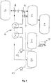
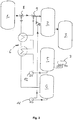
- Figures 1 and 2 illustrate the method according to the invention, wherein Figure 1 Figure 3 shows a flow diagram illustrating the operation of the hydrogenation plant 2 during the first block of time, during Figure 2 Figure 3 shows a flow diagram illustrating the operation of the hydrogenation plant 2 during the second time block.
- the hydrogenation plant 2 used is located in the immediate vicinity of a distillation or conversion plant 1, in which mineral oil is continuously obtained as the end product.
- the mineral oil from the distillation or conversion system 1 is not fed into the hydrogenation system 2, but is instead fed into a first buffer tank 4 via a corresponding three-way valve 8.
- the hydrogenation plant 2 is charged exclusively with vegetable oil, which is conveyed from a second buffer tank 5 to the hydrogenation plant 2 by means of the pump 12.
- a second three-way valve 9 which is set accordingly for this purpose.
- the vegetable oil is preheated via a heat exchanger 6 by the hot mineral oil from the distillation or conversion system, so that the thermal energy of the mineral oil from the distillation or conversion system is not lost but is used sensibly .
- a heat exchanger 6 By the way from the second buffer tank 5 to the hydrogenation system 2, the vegetable oil is preheated via a heat exchanger 6 by the hot mineral oil from the distillation or conversion system, so that the thermal energy of the mineral oil from the distillation or conversion system is not lost but is used sensibly .
- exclusively vegetable oil is desulphurized in the hydrogenation system 2 and fed to a corresponding tank 3 for the end product, for example gasoline or diesel.
- the second buffer tank 5 can be partially filled at irregular intervals, for example by a tank truck 7.
- the catalyst of the hydrogenation plant 2 is gradually deactivated.
- the first time block is therefore ended as soon as further operation of the hydrogenation plant with pure vegetable oil is no longer economical.
- the point in time for this can be recognized, for example, from the temperature of the reactor of the hydrogenation plant. This increases with increasing deactivation of the catalyst.
- the hydrogenation plant After the end of the first time block, the hydrogenation plant is operated with pure mineral oil.
- the two three-way valves 8 and 9 are switched over so that the mineral oil from the distillation or conversion is fed directly to the hydrogenation plant 2 and the vegetable oil is sealed off accordingly.
- a separate line leads from the first buffer tank to the hydrogenation system or opens shortly before the hydrogenation system 2 into the line from the distillation or conversion system 1.
- this separate line there is a valve 10 that is opened during the second time block, so that the mineral oil can be mixed from the first buffer tank 4 by means of the pump 11 to the hot mineral oil resulting from the distillation or conversion and fed to the hydrogenation system 2.
- the second block of time is ended when the reversible deactivation of the catalyst resulting from charging the hydrogenation plant with the vegetable oil has been reversed.
- the appropriate time for this can also be determined on the basis of the temperature of the reactor. The temperature goes back continuously to the value before the vegetable oil processing if the hydrogenation plant is operated with pure mineral oil.
Landscapes
- Chemical & Material Sciences (AREA)
- Oil, Petroleum & Natural Gas (AREA)
- Engineering & Computer Science (AREA)
- Chemical Kinetics & Catalysis (AREA)
- General Chemical & Material Sciences (AREA)
- Organic Chemistry (AREA)
- Production Of Liquid Hydrocarbon Mixture For Refining Petroleum (AREA)
Description
- Die vorliegende Erfindung betrifft ein Verfahren zur Herstellung eines Kraftstoffs aus Mineralöl und Pflanzenöl nach dem Oberbegriff des unabhängigen Anspruchs 1.
- Bei der Herstellung von Kraftstoffen aus Mineralöl wie Benzin und Diesel existieren gesetzliche Vorgaben zur Einhaltung der sogenannten Treibhausgasminderungsquote. Der Gesetzgeber schreibt daher vor, dass bei der Herstellung von Kraftstoffen aus Mineralöl nachwachsende oder regenerativ erzeugte Kraftstoffbestandteile beigemischt werden müssen, die über ihren Lebenszyklus weniger Treibhausgas erzeugen als Mineralölprodukte. Derzeit muss für Ottokraftstoff und Diesel mindestens 4 % Treibhausgasminderung nachgewiesen werden. Die derzeit gültige Quote kann beim Ottokraftstoff durch Beimischung von Ethanol eingehalten werden. Dieselkraftstoff wird FAME, auch als Biodiesel bekannt, beigemischt um die Quote einzuhalten.
- Die Treibhausgasminderungsquote wurde vor kurzem durch den Gesetzgeber von 4 % auf 6 % erhöht, wobei die neue Quote ab dem Jahre 2020 gilt. Um die neuen gesetzlichen Regelungen einhalten zu können, reicht die Beimischung von Ethanol bzw. FAME nicht mehr aus, denn beide Stoffe können nur bis zu einem bestimmten maximal zulässigen Wert beigemischt werden. Um die Vorgaben zu erfüllen, müssen daher weitere nachwachsende oder regenerativ erzeugte Kraftstoffbestandteile, wie zum Beispiel Pflanzenöl beigemischt werden.
- In einer Mineralölraffinerie werden die aus der Rohöldestillation bzw. aus einer Konversionsanlage anfallenden Mineralöle in Hydrieranlagen entschwefelt. Zwei Verfahren zur Beimischung eines regenerativ erzeugten Kraftstoffbestandteils entsprechend dem Oberbegriff des unabhängigen Anspruchs 1 sind aus "A new Development in Renewable Fuels: Green Diesel Introduction" von Holmgren et al. (2007 UOP LLC) bekannt. Das erste dieser Verfahren nach dem Oberbegriff des unabhängigen Anspruchs 1 sieht vor, dass das Pflanzenöl dem Mineralöl bereits vor der Hydrieranlage beigemischt wird. Pflanzenöl und Mineralöl werden somit zusammen der Hydrieranlage zugeführt und entschwefelt. Dieses Verfahren ist unter dem Begriff Co-Hydrotreating bekannt.
-
US8932453 offenbart eine Hydrieranlage, in der sich zwei verschiedene Beschickungen, nämlich Mineralöl und ein Gemisch aus Mineralöl und Pflanzenöl, in Abhängigkeit von dem Katalysator-Deaktivierungsniveau abwechseln. - Das Problem bei der Durchführung des bekannten Co-Hydrotreating-Verfahrens ist, dass anhand des Endprodukts mittels aufwendiger Verfahren nachgewiesen werden muss, welche Ausbeute den pflanzlichen Rohstoffen zuzuordnen ist. Auch hängt es von der aktuellen Gesetzeslage ab, ob eine solche Anrechnung beigemischter Pflanzenöle überhaupt zulässig ist.
- Das zweite in der zuvor erwähnten Druckschrift beschriebene Verfahren sieht vor, dass das Pflanzenöl in einer unabhängigen Hydrieranlage aufbereitet wird und nachfolgend mit dem Endprodukt der Mineralölraffinerie zusammengeführt wird.
- Die vorliegende Erfindung hat sich daher zur Aufgabe gestellt, ein Verfahren nach dem Oberbegriff des unabhängigen Anspruchs 1 anzugeben, das die genannten Probleme umgeht und einen einfachen Nachweis erlaubt, wie hoch der Anteil des eingesetzten Pflanzenöls beim Endprodukt tatsächlich ist. Die Erfindung hat sich ferner zur Aufgabe gestellt, eine Hydrieranlage zur Durchführung des Verfahrens bereitzustellen.
- Die Erfindung wird gelöst durch die Merkmale des unabhängigen Anspruchs 1. Demnach liegt bei einem Verfahren zur Herstellung eines Kraftstoffs aus Mineralöl und Pflanzenöl nach dem Oberbegriff des unabhängigen Anspruchs 1 dann eine erfindungsgemäße Lösung der Aufgabe vor, wenn die Entschwefelung in wiederkehrenden Zeitblöcken erfolgt, wobei die Hydrieranlage in einem ersten Zeitblock ausschließlich mit Pflanzenöl und in einem darauffolgenden zweiten Zeitblock ausschließlich mit Mineralöl beschickt wird.
- Die Erfindung bietet den Vorteil, dass der Prozentsatz des Pflanzenöls im Endprodukt durch eine simple Mengenbilanzierung nachgewiesen werden kann. Das Verfahren kann in einer herkömmlichen Hydrieranlage durchgeführt werden, die zur Verarbeitung von Mineralöl ausgelegt ist. Das Mineralöl oder das Pflanzenöl wird dabei mit Wasserstoff vermischt und bei Temperaturen von bis 400 °C und Drücken von 25 bis 70 bar über einen Katalysator geleitet. Der erste Zeitblock, in dem ausschließlich Pflanzenöl verarbeitet wird, und der zweite Zeitblock, in dem ausschließlich Mineralöl verarbeitet wird, wechseln einander ab. Hydriertes Mineralöl und hydriertes Pflanzenöl können abwechselnd in ein und denselben Tank für das Endprodukt geleitet oder separat gelagert werden.
- Vorteilhafte Ausführungsformen des erfindungsgemäßen Verfahrens sind Gegenstand der Unteransprüche 2 bis 9.
- Gemäß einer bevorzugten Ausführungsform der vorliegenden Erfindung wird das Mineralöl aus einer Destillations- oder Konversionsanlage zugeführt, in der das Mineralöl kontinuierlich anfällt, wobei das Mineralöl während des ersten Zeitblocks in einen ersten Puffertank geleitet und aus diesem während des zweiten Zeitblocks dem aus der Destillations- oder Konversionsanlage kontinuierlich bereitgestellten Mineralöl beigemischt und der Hydrieranlage zugeführt wird. Die beiden Zeitblöcke und die entsprechenden Mengen sind vorzugsweise so aufeinander abgestimmt, dass der erste Puffertank am Ende des zweiten Zeitblocks vollständig entleert ist. Bei dieser Ausführungsform des erfindungsgemäßen Verfahrens kann der kontinuierliche Betrieb in der Destillations- bzw. Konversionsanlage aufrechterhalten werden, ohne das Mineralöl aus der Destillation oder Konversion während des ersten Zeitblocks, in dem ausschließlich Pflanzenöl in der Hydrieranlage verarbeitet wird, zur weiteren Verarbeitung einer weiteren Anlage zuführen zu müssen.
- Bei der zuvor beschriebenen bevorzugten Ausführungsform ist es von besonderem Vorteil, wenn das Pflanzenöl während des ersten Zeitblocks mittels eines Wärmetauschers durch das in den ersten Puffertank ablaufende Mineralöl vorgewärmt und dann der Hydrieranlage zugeführt wird. Dadurch kann die Wärmeenergie des aus der Destillation bzw. Konversion anfallenden Mineralöls genutzt werden, um den Prozess in der Hydrieranlage zu optimieren und Energie einzusparen.
- Gemäß einer weiteren bevorzugten Ausführungsform der vorliegenden Erfindung wird der erste Zeitblock spätestens dann beendet, wenn die aus der Beschickung der Hydrieranlage mit dem Pflanzenöl resultierende reversible Deaktivierung des Katalysators so weit fortgeschritten ist, dass ein weiterer Betrieb der Hydrieranlage mit Pflanzenöl unwirtschaftlich ist. Denn der Betrieb der Hydrieranlage mit reinem Pflanzenöl führt zu einer sogenannten Vergiftung des Katalysators, die allerdings rückgängig gemacht werden kann, wenn die Hydrieranlage wieder mit Mineralöl betrieben wird. Der geeignete Zeitpunkt, um den ersten Zeitblock zu beenden, kann beispielsweise anhand der Temperatur des Reaktors ermittelt werden. Die Temperatur des Reaktors nimmt bei Betrieb der Hydrieranlage mit reinem Pflanzenöl aufgrund der reversiblen Deaktivierung kontinuierlich zu.
- Gemäß einer weiteren bevorzugten Ausführungsform der vorliegenden Erfindung dauert der erste Zeitblock maximal 2 Tage, bevorzugt maximal einen Tag. Es hat sich herausgestellt, dass der Prozess insgesamt am wirtschaftlichsten ist, wenn die Hydrieranlage maximal einen Tag lang mit reinem Pflanzenöl betrieben wird.
- Gemäß einer weiteren bevorzugten Ausführungsform der vorliegenden Erfindung wird der zweite Zeitblock frühestens dann beendet, wenn die aus der Beschickung der Hydrieranlage mit dem Pflanzenöl resultierende reversible Deaktivierung des Katalysators rückgängig gemacht wurde. Der geeignete Zeitpunkt hierfür kann ebenfalls an der Temperatur des Reaktors abgelesen werden. Die Temperatur geht kontinuierlich auf den Wert vor der Pflanzenölverarbeitung zurück, wenn die Hydrieranlage mit reinem Mineralöl betrieben wird. Vorzugsweise dauert der zweite Zeitblock zumindest 5 Tage, weiter vorzugsweise zumindest 7 Tage, weiter vorzugsweise mindestens 10 Tage, und weiter vorzugsweise mindestens 20 Tage an.
- Gemäß einer weiteren bevorzugten Ausführungsform der vorliegenden Erfindung wird das Pflanzenöl der Hydrieranlage aus einem zweiten Puffertank zugeführt. Diese Ausführungsform der vorliegenden Erfindung hat den Vorteil, dass das Pflanzenöl in unregelmäßigen Abständen beispielsweise durch LKW oder Schienenverkehr angeliefert werden kann.
- Gemäß einer weiteren bevorzugten Ausführungsform der vorliegenden Erfindung ist die Durchsatzmenge an Pflanzenöl pro Zeiteinheit, die der Hydrieranlage während des ersten Zeitblocks zugeführt wird, geringer als die Durchsatzmenge an Mineralöl pro Zeiteinheit, die der Hydrieranlage während des zweiten Zeitblocks zugeführt wird. Beispielsweise kann die Hydrieranlage einen Tag lang mit 80 m3/h Pflanzenöl beschickt werden, wobei gleichzeitig 100 m3/h Mineralöl aus Destillation bzw. Konversion in den ersten Puffertank ablaufen. Anschließend kann die Hydrieranlage im zweiten Zeitblock beispielsweise 10 Tage lang mit 100 m3/h Mineralöl aus der Destillation bzw. Konversion und 10 m3/h Mineralöl aus dem ersten Puffertank beschickt werden. Die Hydrieranlage kann im ersten Zeitblock auch beispielsweise zwei Tage lang mit Pflanzenöl beschickt werden, wobei das Mineralöl aus Destillation bzw. Konversion gleichzeitig in den ersten Puffertank abläuft. Anschließend kann die Hydrieranlage im zweiten Zeitblock beispielsweise 20 Tage lang mit Mineralöl aus der Destillation bzw. Konversion und Mineralöl aus dem ersten Puffertank beschickt werden.
- Gemäß einer weiteren bevorzugten Ausführungsform der vorliegenden Erfindung weist die Hydrieranlage eine Regelung auf, mit der sowohl die Zeitdauer des ersten Zeitblocks, während dessen die Hydrieranlage ausschließlich mit Pflanzenöl beschickt wird, als auch die Zeitdauer des zweiten Zeitblocks, während dessen die Hydrieranlage ausschließlich mit Mineralöl beschickt wird, geregelt werden kann. Die Regelung kann auch so eingerichtet sein, dass sie weitere Parameter wie Durchsatzmenge, Temperatur, Treatgasmenge, Wasserstoffpartialdruck usw. regelt, und zwar jeweils optimiert auf den Betrieb mit Mineralöl oder Pflanzenöl.
- Gemäß einer bevorzugten Ausführungsform weist die Hydrieranlage einen Temperatursensor auf, mit dem die Temperatur des Reaktors gemessen wird, wobei die Regelung so eingerichtet ist, dass die Zeitdauer des ersten Zeitblocks und die Zeitdauer des zweiten Zeitblocks in Abhängigkeit der Temperatur des Reaktors geregelt werden.
- Gemäß einer weiteren bevorzugten Ausführungsform weist die Hydrieranlage ein Mengenbilanzierungssystem auf, mit dem der Anteil des hydrierten Pflanzenöls im Endprodukt nachweisbar ist. Das Mengenbilanzierungssystem kann beispielsweise Messgeber aufweisen, mit welchen die Tankstände im zweiten Puffertank und in dem Tank für das Endprodukt ermittelbar sind. Zusätzlich kann auch ein Messgeber vorgesehen sein, mit dem der Tankstand im ersten Puffertank ermittelbar ist.
- Die Erfindung wird im Folgenden anhand von Zeichnungen näher erläutert.
- Es zeigen:
- Figur 1:
- ein Fließdiagramm zur Veranschaulichung des Betriebs der Hydrieranlage während des ersten Zeitblocks, und
- Figur 2:
- ein Fließdiagramm zur Veranschaulichung des Betriebs der Hydrieranlage während des zweiten Zeitblocks.
- Für die folgenden Ausführungen gilt, dass gleiche Teile durch gleiche Bezugszeichen bezeichnet werden. Sofern in einer Figur Bezugszeichen enthalten sind, auf die in der zugehörigen Figurenbeschreibung nicht näher eingegangen wird, so wird auf vorangehende oder nachfolgende Figurenbeschreibungen Bezug genommen.
- Die
Figuren 1 und2 veranschaulichen das erfindungsgemäße Verfahren, wobeiFigur 1 ein Fließdiagramm zeigt, das den Betrieb der Hydrieranlage 2 während des ersten Zeitblocks veranschaulicht, währendFigur 2 ein Fließdiagramm zeigt, das den Betrieb der Hydrieranlage 2 während des zweiten Zeitblocks veranschaulicht. - Die verwendete Hydrieranlage 2 befindet sich in unmittelbarer Nähe einer Destillations- bzw. Konversionsanlage 1, in der als Endprodukt kontinuierlich Mineralöl anfällt. Während des ersten Zeitblocks wird das Mineralöl aus der Destillation- oder Konversionsanlage 1 nicht der Hydrieranlage 2 aufgegeben sondern über ein entsprechendes Dreiwegeventil 8 in einen ersten Puffertank 4 geleitet. Die Hydrieranlage 2 wird während des ersten Zeitblocks ausschließlich mit Pflanzenöl beschickt, das mittels der Pumpe 12 aus einem zweiten Puffertank 5 zur Hydrieranlage 2 gefördert wird. In der Leitung vom zweiten Puffertank 5 zur Hydrieranlage 2 befindet sich ein zweites Dreiwegeventil 9, welches hierzu entsprechend gestellt wird. Auf dem Weg vom zweiten Puffertank 5 zur Hydrieranlage 2 wird das Pflanzenöl über einen Wärmetauscher 6 durch das heiße Mineralöl aus der Destillations- bzw. Konversionsanlage vorgewärmt, sodass die Wärmeenergie des aus der Destillations- bzw. Konversionsanlage stammenden Mineralöl nicht verloren geht sondern sinnvoll genutzt wird. Während des ersten Zeitblocks wird somit ausschließlich Pflanzenöl in der Hydrieranlage 2 entschwefelt und einem entsprechenden Tank 3 für das Endprodukt, beispielsweise Benzin oder Diesel, zugeführt. Der zweite Puffertank 5 kann in unregelmäßigen Abständen teilbefüllt werden, beispielsweise von einem Tank-Lkw 7.
- Während des ersten Zeitblocks wird der Katalysator der Hydrieranlage 2 allmählich deaktiviert. Der erste Zeitblock wird deshalb beendet, sobald ein weiterer Betrieb der Hydrieranlage mit reinem Pflanzenöl nicht mehr wirtschaftlich ist. Der Zeitpunkt hierfür kann beispielsweise über die Temperatur des Reaktors der Hydrieranlage erkannt werden. Diese steigt mit steigender Deaktivierung des Katalysators.
- Nach Beendigung des ersten Zeitblocks wird die Hydrieranlage mit reinem Mineralöl betrieben. Die Pumpe 12, die das Pflanzenöl aus dem zweiten Puffertank 5 zur Hydrieranlage 2 fördert, wird daher abgestellt. Die beiden Dreiwegeventile 8 und 9 werden umgestellt, sodass das Mineralöl aus der Destillation bzw. Konversion direkt zur Hydrieranlage 2 geleitet, und das Pflanzenöl entsprechend abgeriegelt wird. Vom ersten Puffertank führt eine separate Leitung zur Hydrieranlage bzw. mündet kurz vor der Hydrieranlage 2 in die Leitung von der Destillations- bzw. Konversionsanlage 1. In dieser separaten Leitung befindet sich ein Ventil 10, dass während des zweiten Zeitblocks geöffnet wird, sodass das Mineralöl aus dem ersten Puffertank 4 mittels der Pumpe 11 dem aus der Destillation bzw. Konversion anfallenden heißen Mineralöl beigemischt und der Hydrieranlage 2 zugeführt werden kann.
- Der zweite Zeitblock wird beendet, wenn die aus der Beschickung der Hydrieranlage mit dem Pflanzenöl resultierende reversible Deaktivierung des Katalysators rückgängig gemacht wurde. Der geeignete Zeitpunkt hierfür kann ebenfalls anhand der Temperatur des Reaktors ermittelt werden. Die Temperatur geht kontinuierlich auf den Wert vor der Pflanzenölverarbeitung zurück, wenn die Hydrieranlage mit reinem Mineralöl betrieben wird.
Claims (9)
- Verfahren zur Herstellung eines Kraftstoffs aus Mineralöl und Pflanzenöl, bei dem das Mineralöl und das Pflanzenöl in einer Hydrieranlage (2) entschwefelt und zu diesem Zweck mit Wasserstoff vermischt unter hohem Druck und hoher Temperatur über einen Katalysator geführt werden, dadurch gekennzeichnet, dass die Entschwefelung in wiederkehrenden Zeitblöcken erfolgt, wobei die Hydrieranlage in einem ersten Zeitblock ausschließlich mit Pflanzenöl und in einem darauffolgenden zweiten Zeitblock ausschließlich mit Mineralöl beschickt wird.
- Verfahren nach Anspruch 1, dadurch gekennzeichnet, dass das Mineralöl aus einer Destillations- oder Konversionsanlage (1) zugeführt wird, in der das Mineralöl kontinuierlich anfällt, wobei das Mineralöl während des ersten Zeitblocks in einen ersten Puffertank (4) geleitet und aus diesem während des zweiten Zeitblocks dem aus der Destillations- oder Konversionsanlage (1) kontinuierlich bereitgestellten Mineralöl beigemischt und der Hydrieranlage (2) zugeführt wird.
- Verfahren nach Anspruch 2, dadurch gekennzeichnet, dass das Pflanzenöl während des ersten Zeitblocks mittels eines Wärmetauschers (6) durch das in den ersten Puffertank (4) ablaufende Mineralöl vorgewärmt und dann der Hydrieranlage (2) zugeführt wird.
- Verfahren nach einem der Ansprüche 1 bis 3, dadurch gekennzeichnet, dass der erste Zeitblock spätestens dann beendet wird, wenn die aus der Beschickung der Hydrieranlage (2) mit dem Pflanzenöl resultierende reversible Deaktivierung des Katalysators so weit fortgeschritten ist, dass ein weiterer Betrieb der Hydrieranlage (2) mit Pflanzenöl unwirtschaftlich ist.
- Verfahren nach einem der Ansprüche 1 bis 4, dadurch gekennzeichnet, dass der erste Zeitblock maximal zwei Tage, bevorzugt maximal einen Tag andauert.
- Verfahren nach einem der Ansprüche 1 bis 5, dadurch gekennzeichnet, dass der zweite Zeitblock frühestens dann beendet wird, wenn die aus der Beschickung der Hydrieranlage (2) mit dem Pflanzenöl resultierende reversible Deaktivierung des Katalysators rückgängig gemacht wurde.
- Verfahren nach Anspruch 6, dadurch gekennzeichnet, dass der zweite Zeitblock zumindest 5 Tage, vorzugsweise zumindest 7 Tage, weiter vorzugsweise zumindest 10 Tage, und weiter vorzugsweise zumindest 20 Tage andauert.
- Verfahren nach einem der Ansprüche 1 bis 7, dadurch gekennzeichnet, dass das Pflanzenöl der Hydrieranlage (2) aus einem zweiten Puffertank (5) zugeführt wird.
- Verfahren nach einem der Ansprüche 1 bis 8, dadurch gekennzeichnet, dass die Durchsatzmenge an Pflanzenöl pro Zeiteinheit, die der Hydrieranlage (2) während des ersten Zeitblocks zugeführt wird, geringer ist als die Durchsatzmenge an Mineralöl pro Zeiteinheit, die der Hydrieranlage (2) während des zweiten Zeitblocks zugeführt wird.
Applications Claiming Priority (1)
| Application Number | Priority Date | Filing Date | Title |
|---|---|---|---|
| DE102017110512.3A DE102017110512A1 (de) | 2017-05-15 | 2017-05-15 | Verfahren zur Herstellung eines Kraftstoffs aus Mineralöl und Pflanzenöl |
Publications (2)
| Publication Number | Publication Date |
|---|---|
| EP3404080A1 EP3404080A1 (de) | 2018-11-21 |
| EP3404080B1 true EP3404080B1 (de) | 2020-09-02 |
Family
ID=62244282
Family Applications (1)
| Application Number | Title | Priority Date | Filing Date |
|---|---|---|---|
| EP18171422.1A Not-in-force EP3404080B1 (de) | 2017-05-15 | 2018-05-09 | Verfahren zur herstellung eines kraftstoffs aus mineralöl und pflanzenöl |
Country Status (2)
| Country | Link |
|---|---|
| EP (1) | EP3404080B1 (de) |
| DE (1) | DE102017110512A1 (de) |
Family Cites Families (4)
| Publication number | Priority date | Publication date | Assignee | Title |
|---|---|---|---|---|
| US5972057A (en) * | 1997-11-11 | 1999-10-26 | Lonford Development Limited | Method and apparatus for producing diesel fuel oil from waste edible oil |
| US9080117B2 (en) * | 2008-01-22 | 2015-07-14 | GER Enterprises, LLC | Biofuel production method and system |
| US8932453B2 (en) * | 2010-07-23 | 2015-01-13 | Phillips 66 Company | Hydroprocessing process with improved catalyst activity |
| AU2011303586B2 (en) * | 2010-09-14 | 2016-03-24 | Dynamotive Energy Systems | Methods of upgrading biooil to transportation grade hydrocarbon fuels |
-
2017
- 2017-05-15 DE DE102017110512.3A patent/DE102017110512A1/de not_active Withdrawn
-
2018
- 2018-05-09 EP EP18171422.1A patent/EP3404080B1/de not_active Not-in-force
Non-Patent Citations (1)
| Title |
|---|
| None * |
Also Published As
| Publication number | Publication date |
|---|---|
| DE102017110512A1 (de) | 2018-11-15 |
| EP3404080A1 (de) | 2018-11-21 |
Similar Documents
| Publication | Publication Date | Title |
|---|---|---|
| DE102011001108B4 (de) | Verfahren und Vorrichtung zur hydrothermalen Karbonisierung | |
| DE69513669T2 (de) | Verfahren zur beseitigung von überwiegend naphtensäure aus mineralöl | |
| EP0305897A2 (de) | Kompaktstation zur Kühlkreislaufwasserbehandlung | |
| DE102009038128B4 (de) | Verfahren und Vorrichtung zur Einspeisung von Biogas in ein Gasnetz | |
| DE102013106364A1 (de) | Verfahren zur Herstellung eines Polyurethan-Blockschaumstoffes | |
| DE69414699T2 (de) | Verfahren und vorrichtung zur aufbereitung von schmierölen | |
| DE112007001743T5 (de) | Hydrocracking-Verfahren | |
| EP2562237B1 (de) | Verfahren zur bereitstellung eines gases mit sehr hohem methangehalt und dazu ausgelegte anlage | |
| DE112023000008T5 (de) | System und Verfahren zum intelligenten Überwachen und Frühwarnen der fahrzeugmontierten Wasserstoffspeicherung mit Mehrflaschengruppe | |
| DE4409487A1 (de) | Verfahren und Anlage zur Vergärung von biogen-organischen Rohabfällen | |
| DE1080718B (de) | Verfahren zur Entschwefelung von Roherdoelen | |
| DE102012013258A1 (de) | Verfahren zum katalytischen Methanisieren und Methanisierungsanlage | |
| DE2444827C2 (de) | Verfahren zur Hydrierung von Kohle zusammen mit Schweröl und/oder Rückstand aus der Erdölverarbeitung | |
| EP3404080A1 (de) | Verfahren zur herstellung eines kraftstoffs aus mineralöl und pflanzenöl | |
| DE102006044116B3 (de) | Verfahren zur hydrothermalen Vergasung von Biomasse in überkritischem Wasser | |
| EP3733029B1 (de) | Verfahren zum betreiben einer kaffeemaschine | |
| DE2251156A1 (de) | Verfahren zur herstellung von schmieroelen | |
| DE102012104162A1 (de) | Verfahren und System zum Überwachen des Energie- oder Wasserverbrauchs | |
| DE102021122808A1 (de) | Verfahren zum Betreiben einer Wasserstoff-Tankstelle, und Wasserstoff-Hybrid-Tankstelle | |
| DE102006024717A1 (de) | Verfahren zum Betrieb eines Drucklufthebersystems für eine Kleinkläranlage und Drucklufthebersystem | |
| DE19546387C2 (de) | Verfahren und Vorrichtung zur Druckfiltration | |
| DE102023112274B3 (de) | Verfahren zur Erzeugung eines methanangereicherten Gases | |
| DE69121727T2 (de) | Verfahren und vorrichtung in einer anlage zur rückgewinnung von chemikalien in einer sulfatzellstoff-anlage | |
| DE102019213530A1 (de) | Verfahren und Vorrichtung zum Betreiben eines Wasserverteilungssystems | |
| DE102020209095A1 (de) | Verfahren zur Bestimmung eines Versulzungsrisikos einer Kraftstoffversorgungseinrichtung einer Brennkraftmaschine |
Legal Events
| Date | Code | Title | Description |
|---|---|---|---|
| PUAI | Public reference made under article 153(3) epc to a published international application that has entered the european phase |
Free format text: ORIGINAL CODE: 0009012 |
|
| STAA | Information on the status of an ep patent application or granted ep patent |
Free format text: STATUS: THE APPLICATION HAS BEEN PUBLISHED |
|
| AK | Designated contracting states |
Kind code of ref document: A1 Designated state(s): AL AT BE BG CH CY CZ DE DK EE ES FI FR GB GR HR HU IE IS IT LI LT LU LV MC MK MT NL NO PL PT RO RS SE SI SK SM TR |
|
| AX | Request for extension of the european patent |
Extension state: BA ME |
|
| STAA | Information on the status of an ep patent application or granted ep patent |
Free format text: STATUS: REQUEST FOR EXAMINATION WAS MADE |
|
| 17P | Request for examination filed |
Effective date: 20190430 |
|
| RBV | Designated contracting states (corrected) |
Designated state(s): AL AT BE BG CH CY CZ DE DK EE ES FI FR GB GR HR HU IE IS IT LI LT LU LV MC MK MT NL NO PL PT RO RS SE SI SK SM TR |
|
| STAA | Information on the status of an ep patent application or granted ep patent |
Free format text: STATUS: EXAMINATION IS IN PROGRESS |
|
| 17Q | First examination report despatched |
Effective date: 20191119 |
|
| GRAP | Despatch of communication of intention to grant a patent |
Free format text: ORIGINAL CODE: EPIDOSNIGR1 |
|
| STAA | Information on the status of an ep patent application or granted ep patent |
Free format text: STATUS: GRANT OF PATENT IS INTENDED |
|
| INTG | Intention to grant announced |
Effective date: 20200508 |
|
| GRAS | Grant fee paid |
Free format text: ORIGINAL CODE: EPIDOSNIGR3 |
|
| GRAA | (expected) grant |
Free format text: ORIGINAL CODE: 0009210 |
|
| STAA | Information on the status of an ep patent application or granted ep patent |
Free format text: STATUS: THE PATENT HAS BEEN GRANTED |
|
| AK | Designated contracting states |
Kind code of ref document: B1 Designated state(s): AL AT BE BG CH CY CZ DE DK EE ES FI FR GB GR HR HU IE IS IT LI LT LU LV MC MK MT NL NO PL PT RO RS SE SI SK SM TR |
|
| REG | Reference to a national code |
Ref country code: GB Ref legal event code: FG4D Free format text: NOT ENGLISH |
|
| REG | Reference to a national code |
Ref country code: AT Ref legal event code: REF Ref document number: 1308808 Country of ref document: AT Kind code of ref document: T Effective date: 20200915 Ref country code: CH Ref legal event code: EP |
|
| REG | Reference to a national code |
Ref country code: DE Ref legal event code: R096 Ref document number: 502018002313 Country of ref document: DE |
|
| REG | Reference to a national code |
Ref country code: IE Ref legal event code: FG4D Free format text: LANGUAGE OF EP DOCUMENT: GERMAN |
|
| REG | Reference to a national code |
Ref country code: LT Ref legal event code: MG4D |
|
| PG25 | Lapsed in a contracting state [announced via postgrant information from national office to epo] |
Ref country code: FI Free format text: LAPSE BECAUSE OF FAILURE TO SUBMIT A TRANSLATION OF THE DESCRIPTION OR TO PAY THE FEE WITHIN THE PRESCRIBED TIME-LIMIT Effective date: 20200902 Ref country code: NO Free format text: LAPSE BECAUSE OF FAILURE TO SUBMIT A TRANSLATION OF THE DESCRIPTION OR TO PAY THE FEE WITHIN THE PRESCRIBED TIME-LIMIT Effective date: 20201202 Ref country code: GR Free format text: LAPSE BECAUSE OF FAILURE TO SUBMIT A TRANSLATION OF THE DESCRIPTION OR TO PAY THE FEE WITHIN THE PRESCRIBED TIME-LIMIT Effective date: 20201203 Ref country code: HR Free format text: LAPSE BECAUSE OF FAILURE TO SUBMIT A TRANSLATION OF THE DESCRIPTION OR TO PAY THE FEE WITHIN THE PRESCRIBED TIME-LIMIT Effective date: 20200902 Ref country code: BG Free format text: LAPSE BECAUSE OF FAILURE TO SUBMIT A TRANSLATION OF THE DESCRIPTION OR TO PAY THE FEE WITHIN THE PRESCRIBED TIME-LIMIT Effective date: 20201202 Ref country code: SE Free format text: LAPSE BECAUSE OF FAILURE TO SUBMIT A TRANSLATION OF THE DESCRIPTION OR TO PAY THE FEE WITHIN THE PRESCRIBED TIME-LIMIT Effective date: 20200902 Ref country code: LT Free format text: LAPSE BECAUSE OF FAILURE TO SUBMIT A TRANSLATION OF THE DESCRIPTION OR TO PAY THE FEE WITHIN THE PRESCRIBED TIME-LIMIT Effective date: 20200902 |
|
| REG | Reference to a national code |
Ref country code: NL Ref legal event code: MP Effective date: 20200902 |
|
| PG25 | Lapsed in a contracting state [announced via postgrant information from national office to epo] |
Ref country code: PL Free format text: LAPSE BECAUSE OF FAILURE TO SUBMIT A TRANSLATION OF THE DESCRIPTION OR TO PAY THE FEE WITHIN THE PRESCRIBED TIME-LIMIT Effective date: 20200902 Ref country code: LV Free format text: LAPSE BECAUSE OF FAILURE TO SUBMIT A TRANSLATION OF THE DESCRIPTION OR TO PAY THE FEE WITHIN THE PRESCRIBED TIME-LIMIT Effective date: 20200902 Ref country code: RS Free format text: LAPSE BECAUSE OF FAILURE TO SUBMIT A TRANSLATION OF THE DESCRIPTION OR TO PAY THE FEE WITHIN THE PRESCRIBED TIME-LIMIT Effective date: 20200902 |
|
| PG25 | Lapsed in a contracting state [announced via postgrant information from national office to epo] |
Ref country code: EE Free format text: LAPSE BECAUSE OF FAILURE TO SUBMIT A TRANSLATION OF THE DESCRIPTION OR TO PAY THE FEE WITHIN THE PRESCRIBED TIME-LIMIT Effective date: 20200902 Ref country code: CZ Free format text: LAPSE BECAUSE OF FAILURE TO SUBMIT A TRANSLATION OF THE DESCRIPTION OR TO PAY THE FEE WITHIN THE PRESCRIBED TIME-LIMIT Effective date: 20200902 Ref country code: RO Free format text: LAPSE BECAUSE OF FAILURE TO SUBMIT A TRANSLATION OF THE DESCRIPTION OR TO PAY THE FEE WITHIN THE PRESCRIBED TIME-LIMIT Effective date: 20200902 Ref country code: PT Free format text: LAPSE BECAUSE OF FAILURE TO SUBMIT A TRANSLATION OF THE DESCRIPTION OR TO PAY THE FEE WITHIN THE PRESCRIBED TIME-LIMIT Effective date: 20210104 Ref country code: SM Free format text: LAPSE BECAUSE OF FAILURE TO SUBMIT A TRANSLATION OF THE DESCRIPTION OR TO PAY THE FEE WITHIN THE PRESCRIBED TIME-LIMIT Effective date: 20200902 |
|
| PG25 | Lapsed in a contracting state [announced via postgrant information from national office to epo] |
Ref country code: IS Free format text: LAPSE BECAUSE OF FAILURE TO SUBMIT A TRANSLATION OF THE DESCRIPTION OR TO PAY THE FEE WITHIN THE PRESCRIBED TIME-LIMIT Effective date: 20210102 Ref country code: AL Free format text: LAPSE BECAUSE OF FAILURE TO SUBMIT A TRANSLATION OF THE DESCRIPTION OR TO PAY THE FEE WITHIN THE PRESCRIBED TIME-LIMIT Effective date: 20200902 Ref country code: ES Free format text: LAPSE BECAUSE OF FAILURE TO SUBMIT A TRANSLATION OF THE DESCRIPTION OR TO PAY THE FEE WITHIN THE PRESCRIBED TIME-LIMIT Effective date: 20200902 |
|
| REG | Reference to a national code |
Ref country code: DE Ref legal event code: R097 Ref document number: 502018002313 Country of ref document: DE |
|
| PG25 | Lapsed in a contracting state [announced via postgrant information from national office to epo] |
Ref country code: SK Free format text: LAPSE BECAUSE OF FAILURE TO SUBMIT A TRANSLATION OF THE DESCRIPTION OR TO PAY THE FEE WITHIN THE PRESCRIBED TIME-LIMIT Effective date: 20200902 |
|
| PLBE | No opposition filed within time limit |
Free format text: ORIGINAL CODE: 0009261 |
|
| STAA | Information on the status of an ep patent application or granted ep patent |
Free format text: STATUS: NO OPPOSITION FILED WITHIN TIME LIMIT |
|
| PGFP | Annual fee paid to national office [announced via postgrant information from national office to epo] |
Ref country code: DE Payment date: 20210520 Year of fee payment: 4 |
|
| 26N | No opposition filed |
Effective date: 20210603 |
|
| PG25 | Lapsed in a contracting state [announced via postgrant information from national office to epo] |
Ref country code: SI Free format text: LAPSE BECAUSE OF FAILURE TO SUBMIT A TRANSLATION OF THE DESCRIPTION OR TO PAY THE FEE WITHIN THE PRESCRIBED TIME-LIMIT Effective date: 20200902 Ref country code: DK Free format text: LAPSE BECAUSE OF FAILURE TO SUBMIT A TRANSLATION OF THE DESCRIPTION OR TO PAY THE FEE WITHIN THE PRESCRIBED TIME-LIMIT Effective date: 20200902 |
|
| PG25 | Lapsed in a contracting state [announced via postgrant information from national office to epo] |
Ref country code: IT Free format text: LAPSE BECAUSE OF FAILURE TO SUBMIT A TRANSLATION OF THE DESCRIPTION OR TO PAY THE FEE WITHIN THE PRESCRIBED TIME-LIMIT Effective date: 20200902 |
|
| REG | Reference to a national code |
Ref country code: CH Ref legal event code: PL |
|
| PG25 | Lapsed in a contracting state [announced via postgrant information from national office to epo] |
Ref country code: MC Free format text: LAPSE BECAUSE OF FAILURE TO SUBMIT A TRANSLATION OF THE DESCRIPTION OR TO PAY THE FEE WITHIN THE PRESCRIBED TIME-LIMIT Effective date: 20200902 Ref country code: LI Free format text: LAPSE BECAUSE OF NON-PAYMENT OF DUE FEES Effective date: 20210531 Ref country code: CH Free format text: LAPSE BECAUSE OF NON-PAYMENT OF DUE FEES Effective date: 20210531 Ref country code: LU Free format text: LAPSE BECAUSE OF NON-PAYMENT OF DUE FEES Effective date: 20210509 |
|
| REG | Reference to a national code |
Ref country code: BE Ref legal event code: MM Effective date: 20210531 |
|
| PG25 | Lapsed in a contracting state [announced via postgrant information from national office to epo] |
Ref country code: IE Free format text: LAPSE BECAUSE OF NON-PAYMENT OF DUE FEES Effective date: 20210509 |
|
| PG25 | Lapsed in a contracting state [announced via postgrant information from national office to epo] |
Ref country code: FR Free format text: LAPSE BECAUSE OF NON-PAYMENT OF DUE FEES Effective date: 20210531 |
|
| PG25 | Lapsed in a contracting state [announced via postgrant information from national office to epo] |
Ref country code: BE Free format text: LAPSE BECAUSE OF NON-PAYMENT OF DUE FEES Effective date: 20210531 |
|
| REG | Reference to a national code |
Ref country code: DE Ref legal event code: R119 Ref document number: 502018002313 Country of ref document: DE |
|
| GBPC | Gb: european patent ceased through non-payment of renewal fee |
Effective date: 20220509 |
|
| PG25 | Lapsed in a contracting state [announced via postgrant information from national office to epo] |
Ref country code: GB Free format text: LAPSE BECAUSE OF NON-PAYMENT OF DUE FEES Effective date: 20220509 Ref country code: DE Free format text: LAPSE BECAUSE OF NON-PAYMENT OF DUE FEES Effective date: 20221201 |
|
| PG25 | Lapsed in a contracting state [announced via postgrant information from national office to epo] |
Ref country code: NL Free format text: LAPSE BECAUSE OF NON-PAYMENT OF DUE FEES Effective date: 20200923 Ref country code: CY Free format text: LAPSE BECAUSE OF FAILURE TO SUBMIT A TRANSLATION OF THE DESCRIPTION OR TO PAY THE FEE WITHIN THE PRESCRIBED TIME-LIMIT Effective date: 20200902 |
|
| PG25 | Lapsed in a contracting state [announced via postgrant information from national office to epo] |
Ref country code: HU Free format text: LAPSE BECAUSE OF FAILURE TO SUBMIT A TRANSLATION OF THE DESCRIPTION OR TO PAY THE FEE WITHIN THE PRESCRIBED TIME-LIMIT; INVALID AB INITIO Effective date: 20180509 |
|
| PG25 | Lapsed in a contracting state [announced via postgrant information from national office to epo] |
Ref country code: MK Free format text: LAPSE BECAUSE OF FAILURE TO SUBMIT A TRANSLATION OF THE DESCRIPTION OR TO PAY THE FEE WITHIN THE PRESCRIBED TIME-LIMIT Effective date: 20200902 |
|
| PG25 | Lapsed in a contracting state [announced via postgrant information from national office to epo] |
Ref country code: TR Free format text: LAPSE BECAUSE OF FAILURE TO SUBMIT A TRANSLATION OF THE DESCRIPTION OR TO PAY THE FEE WITHIN THE PRESCRIBED TIME-LIMIT Effective date: 20200902 |
|
| REG | Reference to a national code |
Ref country code: AT Ref legal event code: MM01 Ref document number: 1308808 Country of ref document: AT Kind code of ref document: T Effective date: 20230509 |
|
| PG25 | Lapsed in a contracting state [announced via postgrant information from national office to epo] |
Ref country code: AT Free format text: LAPSE BECAUSE OF NON-PAYMENT OF DUE FEES Effective date: 20230509 |
|
| PG25 | Lapsed in a contracting state [announced via postgrant information from national office to epo] |
Ref country code: AT Free format text: LAPSE BECAUSE OF NON-PAYMENT OF DUE FEES Effective date: 20230509 |
|
| PG25 | Lapsed in a contracting state [announced via postgrant information from national office to epo] |
Ref country code: MT Free format text: LAPSE BECAUSE OF FAILURE TO SUBMIT A TRANSLATION OF THE DESCRIPTION OR TO PAY THE FEE WITHIN THE PRESCRIBED TIME-LIMIT Effective date: 20200902 |
|
| PGFP | Annual fee paid to national office [announced via postgrant information from national office to epo] |
Ref country code: AT Payment date: 20260410 Year of fee payment: 5 |