EP3404214A1 - Agencement de joint de pointe d'aubes et morteur à turbiner à gaz ayant un tel agencement - Google Patents
Agencement de joint de pointe d'aubes et morteur à turbiner à gaz ayant un tel agencement Download PDFInfo
- Publication number
- EP3404214A1 EP3404214A1 EP18170407.3A EP18170407A EP3404214A1 EP 3404214 A1 EP3404214 A1 EP 3404214A1 EP 18170407 A EP18170407 A EP 18170407A EP 3404214 A1 EP3404214 A1 EP 3404214A1
- Authority
- EP
- European Patent Office
- Prior art keywords
- boas
- shroud
- aft
- facing
- face
- Prior art date
- Legal status (The legal status is an assumption and is not a legal conclusion. Google has not performed a legal analysis and makes no representation as to the accuracy of the status listed.)
- Granted
Links
Images

Classifications
-
- F—MECHANICAL ENGINEERING; LIGHTING; HEATING; WEAPONS; BLASTING
- F01—MACHINES OR ENGINES IN GENERAL; ENGINE PLANTS IN GENERAL; STEAM ENGINES
- F01D—NON-POSITIVE DISPLACEMENT MACHINES OR ENGINES, e.g. STEAM TURBINES
- F01D11/00—Preventing or minimising internal leakage of working-fluid, e.g. between stages
- F01D11/005—Sealing means between non relatively rotating elements
-
- F—MECHANICAL ENGINEERING; LIGHTING; HEATING; WEAPONS; BLASTING
- F01—MACHINES OR ENGINES IN GENERAL; ENGINE PLANTS IN GENERAL; STEAM ENGINES
- F01D—NON-POSITIVE DISPLACEMENT MACHINES OR ENGINES, e.g. STEAM TURBINES
- F01D11/00—Preventing or minimising internal leakage of working-fluid, e.g. between stages
- F01D11/08—Preventing or minimising internal leakage of working-fluid, e.g. between stages for sealing space between rotor blade tips and stator
- F01D11/14—Adjusting or regulating tip-clearance, i.e. distance between rotor-blade tips and stator casing
-
- F—MECHANICAL ENGINEERING; LIGHTING; HEATING; WEAPONS; BLASTING
- F01—MACHINES OR ENGINES IN GENERAL; ENGINE PLANTS IN GENERAL; STEAM ENGINES
- F01D—NON-POSITIVE DISPLACEMENT MACHINES OR ENGINES, e.g. STEAM TURBINES
- F01D11/00—Preventing or minimising internal leakage of working-fluid, e.g. between stages
- F01D11/08—Preventing or minimising internal leakage of working-fluid, e.g. between stages for sealing space between rotor blade tips and stator
-
- F—MECHANICAL ENGINEERING; LIGHTING; HEATING; WEAPONS; BLASTING
- F01—MACHINES OR ENGINES IN GENERAL; ENGINE PLANTS IN GENERAL; STEAM ENGINES
- F01D—NON-POSITIVE DISPLACEMENT MACHINES OR ENGINES, e.g. STEAM TURBINES
- F01D11/00—Preventing or minimising internal leakage of working-fluid, e.g. between stages
- F01D11/08—Preventing or minimising internal leakage of working-fluid, e.g. between stages for sealing space between rotor blade tips and stator
- F01D11/14—Adjusting or regulating tip-clearance, i.e. distance between rotor-blade tips and stator casing
- F01D11/16—Adjusting or regulating tip-clearance, i.e. distance between rotor-blade tips and stator casing by self-adjusting means
-
- F—MECHANICAL ENGINEERING; LIGHTING; HEATING; WEAPONS; BLASTING
- F16—ENGINEERING ELEMENTS AND UNITS; GENERAL MEASURES FOR PRODUCING AND MAINTAINING EFFECTIVE FUNCTIONING OF MACHINES OR INSTALLATIONS; THERMAL INSULATION IN GENERAL
- F16J—PISTONS; CYLINDERS; SEALINGS
- F16J15/00—Sealings
- F16J15/02—Sealings between relatively-stationary surfaces
- F16J15/06—Sealings between relatively-stationary surfaces with solid packing compressed between sealing surfaces
- F16J15/08—Sealings between relatively-stationary surfaces with solid packing compressed between sealing surfaces with exclusively metal packing
- F16J15/0887—Sealings between relatively-stationary surfaces with solid packing compressed between sealing surfaces with exclusively metal packing the sealing effect being obtained by elastic deformation of the packing
-
- F—MECHANICAL ENGINEERING; LIGHTING; HEATING; WEAPONS; BLASTING
- F05—INDEXING SCHEMES RELATING TO ENGINES OR PUMPS IN VARIOUS SUBCLASSES OF CLASSES F01-F04
- F05D—INDEXING SCHEME FOR ASPECTS RELATING TO NON-POSITIVE-DISPLACEMENT MACHINES OR ENGINES, GAS-TURBINES OR JET-PROPULSION PLANTS
- F05D2220/00—Application
- F05D2220/30—Application in turbines
- F05D2220/32—Application in turbines in gas turbines
-
- F—MECHANICAL ENGINEERING; LIGHTING; HEATING; WEAPONS; BLASTING
- F05—INDEXING SCHEMES RELATING TO ENGINES OR PUMPS IN VARIOUS SUBCLASSES OF CLASSES F01-F04
- F05D—INDEXING SCHEME FOR ASPECTS RELATING TO NON-POSITIVE-DISPLACEMENT MACHINES OR ENGINES, GAS-TURBINES OR JET-PROPULSION PLANTS
- F05D2240/00—Components
- F05D2240/10—Stators
- F05D2240/11—Shroud seal segments
-
- F—MECHANICAL ENGINEERING; LIGHTING; HEATING; WEAPONS; BLASTING
- F05—INDEXING SCHEMES RELATING TO ENGINES OR PUMPS IN VARIOUS SUBCLASSES OF CLASSES F01-F04
- F05D—INDEXING SCHEME FOR ASPECTS RELATING TO NON-POSITIVE-DISPLACEMENT MACHINES OR ENGINES, GAS-TURBINES OR JET-PROPULSION PLANTS
- F05D2240/00—Components
- F05D2240/55—Seals
-
- F—MECHANICAL ENGINEERING; LIGHTING; HEATING; WEAPONS; BLASTING
- F05—INDEXING SCHEMES RELATING TO ENGINES OR PUMPS IN VARIOUS SUBCLASSES OF CLASSES F01-F04
- F05D—INDEXING SCHEME FOR ASPECTS RELATING TO NON-POSITIVE-DISPLACEMENT MACHINES OR ENGINES, GAS-TURBINES OR JET-PROPULSION PLANTS
- F05D2250/00—Geometry
- F05D2250/10—Two-dimensional
- F05D2250/18—Two-dimensional patterned
- F05D2250/185—Two-dimensional patterned serpentine-like
-
- F—MECHANICAL ENGINEERING; LIGHTING; HEATING; WEAPONS; BLASTING
- F05—INDEXING SCHEMES RELATING TO ENGINES OR PUMPS IN VARIOUS SUBCLASSES OF CLASSES F01-F04
- F05D—INDEXING SCHEME FOR ASPECTS RELATING TO NON-POSITIVE-DISPLACEMENT MACHINES OR ENGINES, GAS-TURBINES OR JET-PROPULSION PLANTS
- F05D2260/00—Function
- F05D2260/30—Retaining components in desired mutual position
- F05D2260/38—Retaining components in desired mutual position by a spring, i.e. spring loaded or biased towards a certain position
-
- F—MECHANICAL ENGINEERING; LIGHTING; HEATING; WEAPONS; BLASTING
- F05—INDEXING SCHEMES RELATING TO ENGINES OR PUMPS IN VARIOUS SUBCLASSES OF CLASSES F01-F04
- F05D—INDEXING SCHEME FOR ASPECTS RELATING TO NON-POSITIVE-DISPLACEMENT MACHINES OR ENGINES, GAS-TURBINES OR JET-PROPULSION PLANTS
- F05D2300/00—Materials; Properties thereof
- F05D2300/10—Metals, alloys or intermetallic compounds
- F05D2300/17—Alloys
- F05D2300/175—Superalloys
-
- F—MECHANICAL ENGINEERING; LIGHTING; HEATING; WEAPONS; BLASTING
- F05—INDEXING SCHEMES RELATING TO ENGINES OR PUMPS IN VARIOUS SUBCLASSES OF CLASSES F01-F04
- F05D—INDEXING SCHEME FOR ASPECTS RELATING TO NON-POSITIVE-DISPLACEMENT MACHINES OR ENGINES, GAS-TURBINES OR JET-PROPULSION PLANTS
- F05D2300/00—Materials; Properties thereof
- F05D2300/10—Metals, alloys or intermetallic compounds
- F05D2300/17—Alloys
- F05D2300/177—Ni - Si alloys
-
- F—MECHANICAL ENGINEERING; LIGHTING; HEATING; WEAPONS; BLASTING
- F05—INDEXING SCHEMES RELATING TO ENGINES OR PUMPS IN VARIOUS SUBCLASSES OF CLASSES F01-F04
- F05D—INDEXING SCHEME FOR ASPECTS RELATING TO NON-POSITIVE-DISPLACEMENT MACHINES OR ENGINES, GAS-TURBINES OR JET-PROPULSION PLANTS
- F05D2300/00—Materials; Properties thereof
- F05D2300/50—Intrinsic material properties or characteristics
- F05D2300/501—Elasticity
-
- Y—GENERAL TAGGING OF NEW TECHNOLOGICAL DEVELOPMENTS; GENERAL TAGGING OF CROSS-SECTIONAL TECHNOLOGIES SPANNING OVER SEVERAL SECTIONS OF THE IPC; TECHNICAL SUBJECTS COVERED BY FORMER USPC CROSS-REFERENCE ART COLLECTIONS [XRACs] AND DIGESTS
- Y02—TECHNOLOGIES OR APPLICATIONS FOR MITIGATION OR ADAPTATION AGAINST CLIMATE CHANGE
- Y02T—CLIMATE CHANGE MITIGATION TECHNOLOGIES RELATED TO TRANSPORTATION
- Y02T50/00—Aeronautics or air transport
- Y02T50/60—Efficient propulsion technologies, e.g. for aircraft
Definitions
- the present disclosure is directed to a seal for reducing radial air leakage between a blade outer air seal (BOAS) and a shroud block of a compressor section or a turbine section of a gas turbine engine.
- BOAS blade outer air seal
- Gas turbine engines such as those that power modern commercial and military aircraft, may include a fan section to propel the aircraft, a compressor section to pressurize a supply of air from the fan section, a combustor section to burn fuel in the presence of the pressurized air, and a turbine section to extract energy from the resultant combustion gases and to generate thrust.
- the compressor section and turbine section each have multiple stages of rotors that rotate about a central axis and multiple stages of stators that are stationary relative to the central axis.
- a blade outer air seal is positioned radially outward from the rotors and is connected to a shroud block that is located radially outward from the blade outer air seal.
- the BOAS assembly includes a rotor blade configured to rotate about an axis.
- the BOAS assembly also includes a BOAS positioned radially outward from the rotor blade and having a forward-facing BOAS face.
- the BOAS assembly also includes a shroud block positioned radially outward from the BOAS, having an aft-facing shroud face, and being configured to support the BOAS.
- the BOAS assembly also includes a first bellows seal extending from the forward-facing BOAS face to the aft-facing shroud face and configured to reduce fluid leakage radially between the BOAS and the shroud block.
- any of the foregoing embodiments may also include a second bellows seal, wherein the BOAS further includes an aft-facing BOAS face, the shroud block further includes a forward-facing shroud face, and the second bellows seal extends from the aft-facing BOAS face to the forward-facing shroud face and is configured to further reduce the fluid leakage radially between the BOAS and the shroud block.
- the shroud block includes a shroud main body, a shroud forward radial portion extending radially inward from the shroud main body, and a shroud forward axial portion extending axially aft from the shroud forward radial portion
- the BOAS includes a BOAS main body, a BOAS forward radial portion extending radially outward from the BOAS main body, and a BOAS forward axial portion extending axially forward from the BOAS forward radial portion
- the forward-facing BOAS face is defined by the BOAS forward radial portion
- the aft-facing shroud face is defined by the shroud forward radial portion.
- the BOAS forward axial portion is received between the shroud main body and the shroud forward axial portion to resist separation of the BOAS from the shroud block.
- the BOAS main body includes a forward wing extending axially forward from the BOAS forward radial portion.
- the BOAS forward radial portion has a forward inner portion connected to the BOAS main body and a forward outer portion connected to the forward inner portion and extending radially outward from the forward inner portion, and the BOAS forward axial portion is positioned radially between the forward outer portion and the forward inner portion.
- an axial tolerance exists between the BOAS forward axial portion and the shroud forward radial portion to allow axial movement of the BOAS relative to the shroud block.
- an axial gap extends from the forward-facing BOAS face to the aft-facing shroud face, and the first bellows seal has an axial length in a fully extended position that is greater than the axial gap such that the first bellows seal is compressed between the forward-facing BOAS face and the aft-facing shroud face.
- the first bellows seal includes at least one of a cobalt based alloy or a nickel based alloy.
- the BOAS assembly includes a rotor blade configured to rotate about an axis.
- the BOAS assembly also includes a blade outer air seal (BOAS) positioned radially outward from the rotor blade and having an aft-facing BOAS face.
- the BOAS assembly also includes a shroud block positioned radially outward from the BOAS, having a forward-facing shroud face, and being configured to support the BOAS.
- the BOAS assembly also includes a bellows seal extending from the aft-facing BOAS face to the forward-facing shroud face and configured to reduce fluid leakage radially between the BOAS and the shroud block.
- the shroud block includes a shroud main body, a shroud aft radial portion extending radially inward from the shroud main body, and a shroud aft axial portion extending axially forward from the shroud aft radial portion
- the BOAS includes a BOAS main body, a BOAS aft radial portion extending radially outward from the BOAS main body, and a BOAS aft axial portion extending axially aft from the BOAS aft radial portion
- the aft-facing BOAS face is defined by the BOAS aft radial portion
- the forward-facing shroud face is defined by the shroud aft radial portion.
- the BOAS aft axial portion is received between the shroud main body and the shroud aft axial portion to resist separation of the BOAS from the shroud block.
- the BOAS main body includes an aft wing extending axially aft from the BOAS aft radial portion.
- the BOAS aft radial portion has an aft inner portion connected to the BOAS main body and an aft outer portion connected to the aft inner portion and extending radially outward from the aft inner portion, and the BOAS aft axial portion is positioned radially between the aft outer portion and the aft inner portion.
- an axial tolerance exists between the BOAS aft axial portion and the shroud aft radial portion to allow axial movement of the BOAS relative to the shroud block.
- an axial gap exists from the aft-facing BOAS face to the forward-facing shroud face, and the bellows seal has an axial length in a fully extended position that is greater than the axial gap such that the bellows seal is compressed between the aft-facing BOAS face and the forward-facing shroud face.
- the bellows seal includes at least one of a cobalt based alloy or a nickel based alloy.
- the gas turbine engine having an axis.
- the gas turbine engine includes a compressor section configured to compress a fluid.
- the gas turbine engine also includes a combustor section configured to mix the fluid with fuel and combust the fluid and the fuel to generate exhaust.
- the gas turbine engine also includes a turbine section configured to receive the exhaust and convert the exhaust into torque.
- At least one of the compressor section or the turbine section includes a rotor blade configured to rotate about the axis, a blade outer air seal (BOAS) positioned radially outward from the rotor blade and having a forward-facing BOAS face, a shroud block positioned radially outward from the BOAS, having an aft-facing shroud face, and being configured to support the BOAS, and a first bellows seal extending from the forward-facing BOAS face to the aft-facing shroud face and configured to reduce fluid leakage radially between the BOAS and the shroud block.
- BOAS blade outer air seal
- the BOAS further includes an aft-facing BOAS face
- the shroud block further includes a forward-facing shroud face
- the at least one of the compressor section or the turbine section further includes a second bellows seal that extends from the aft-facing BOAS face to the forward-facing shroud face and is configured to further reduce the fluid leakage radially between the BOAS and the shroud block.
- the shroud block includes a shroud main body, a shroud forward radial portion extending radially inward from the shroud main body, and a shroud forward axial portion extending axially aft from the shroud forward radial portion
- the BOAS includes a BOAS main body, a BOAS forward radial portion extending radially outward from the BOAS main body, and a BOAS forward axial portion extending axially forward from the BOAS forward radial portion
- the forward-facing BOAS face is defined by the BOAS forward radial portion
- the aft-facing shroud face is defined by the shroud forward radial portion.
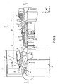
- a gas turbine engine 20 is provided.
- An A-R-C axis is shown throughout the drawings to illustrate the axial, radial, and circumferential directions, respectively.
- the gas turbine engine 20 may be a two-spool turbofan that generally incorporates a fan section 22, a compressor section 24, a combustor section 26 and a turbine section 28.
- Alternative engines may include, for example, an augmentor section among other systems or features.
- the fan section 22 can drive coolant (e.g., air) along a bypass flow path B while the compressor section 24 can drive coolant along a core flow path C for compression and communication into the combustor section 26 then expansion through the turbine section 28.
- turbofan gas turbine engine 20 Although depicted as a two-spool turbofan gas turbine engine 20 herein, it should be understood that the concepts described herein are not limited to use with two-spool turbofans as the teachings may be applied to other types of turbine engines including turbojet, turboprop, turboshaft, or power generation turbines, with or without geared fan, geared compressor or three-spool architectures.
- the gas turbine engine 20 may generally comprise a low speed spool 30 and a high speed spool 32 mounted for rotation about an engine central longitudinal axis A-A' relative to an engine static structure 36 or engine case via several bearing systems 38, 38-1, and 38-2. It should be understood that various bearing systems 38 at various locations may alternatively or additionally be provided, including for example, the bearing system 38, the bearing system 38-1, and the bearing system 38-2.
- the low speed spool 30 may generally comprise an inner shaft 40 that interconnects a fan 42, a low pressure compressor 44 and a low pressure turbine 46.
- the inner shaft 40 may be connected to the fan 42 through a geared architecture 48 that can drive the fan 42 at a lower speed than the low speed spool 30.
- the geared architecture 48 may comprise a gear assembly 60 enclosed within a gear housing 62.
- the gear assembly 60 couples the inner shaft 40 to a rotating fan structure.
- the high speed spool 32 may comprise an outer shaft 50 that interconnects a high pressure compressor 52 and high pressure turbine 54.
- a combustor 26 may be located between high pressure compressor 52 and high pressure turbine 54.
- a mid-turbine frame 57 of the engine static structure 36 may be located generally between the high pressure turbine 54 and the low pressure turbine 46.
- Mid-turbine frame 57 may support one or more bearing systems 38 in the turbine section 28.
- the inner shaft 40 and the outer shaft 50 may be concentric and rotate via bearing systems 38 about the engine central longitudinal axis A-A', which is collinear with their longitudinal axes.
- A-A' the engine central longitudinal axis A-A'
- the airflow of core flow path C may be received and conditioned by a fan exit stator 70. After conditioning, the airflow of core flow path C may be compressed by the low pressure compressor 44 then the high pressure compressor 52, mixed and burned with fuel in the combustor 26, then expanded over the high pressure turbine 54 and the low pressure turbine 46.
- the turbines 46, 54 rotationally drive the respective low speed spool 30 and high speed spool 32 in response to the expansion.
- the gas turbine engine 20 may be, for example, a high-bypass ratio geared engine. In various embodiments, the bypass ratio of the gas turbine engine 20 may be greater than about six (6). In various embodiments, the bypass ratio of the gas turbine engine 20 may be greater than ten (10).
- the geared architecture 48 may be an epicyclic gear train, such as a star gear system (sun gear in meshing engagement with a plurality of star gears supported by a carrier and in meshing engagement with a ring gear) or other gear system. The geared architecture 48 may have a gear reduction ratio of greater than about 2.3 and the low pressure turbine 46 may have a pressure ratio that is greater than about five (5).
- the bypass ratio of the gas turbine engine 20 is greater than about ten (10:1).
- the diameter of the fan 42 may be significantly larger than that of the low pressure compressor 44, and the low pressure turbine 46 may have a pressure ratio that is greater than about five (5:1).
- the low pressure turbine 46 pressure ratio may be measured prior to the inlet of the low pressure turbine 46 as related to the pressure at the outlet of the low pressure turbine 46 prior to an exhaust nozzle. It should be understood, however, that the above parameters are exemplary of various embodiments of a suitable geared architecture engine and that the present disclosure contemplates other gas turbine engines including direct drive turbofans.
- a gas turbine engine may comprise an industrial gas turbine (IGT) or a geared engine, such as a geared turbofan, or non-geared engine, such as a turbofan, a turboshaft, or may comprise any gas turbine engine as desired.
- IGT industrial gas turbine
- a geared engine such as a geared turbofan, or non-geared engine, such as a turbofan, a turboshaft, or may
- the low pressure compressor 44, the high pressure compressor 52, the low pressure turbine 46, and the high pressure turbine 54 may comprise one or more stages or sets of rotating blades and one or more stages or sets of stationary vanes axially interspersed with the associated blade stages but non-rotating about engine central longitudinal axis A-A'.
- the compressor and turbine sections 24, 28 may be referred to as rotor systems.
- Within the rotor systems of the gas turbine engine 20 are multiple rotor disks, which may include one or more cover plates or minidisks. Minidisks may be configured to receive balancing weights or inserts for balancing the rotor systems.
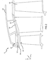
- a portion of the high pressure turbine section 54 includes a first rotor blade 200, a vane 202, and a second rotor blade 204.
- the first rotor blade 200 and the second rotor blade 204 are each configured to rotate about the axis A-A' relative to vane 202 in response to receiving a flow of fluid from the combustor section 26.
- power from the flow is converted to mechanical power, or torque, by the first rotor blade 200 and the second rotor blade 204.
- the vane 202 is coupled to a frame 214 of the high pressure turbine 54 and conditions the flow of air between the first rotor blade 200 and the second rotor blade 204.
- the vane 202 thus acts as a stator and does not rotate relative to the axis A-A'.
- a blade outer air seal (BOAS) 208 is located radially outward from the first rotor blade 200.
- the BOAS 208 is designed to function as a seal to reduce axial air leakage between the first rotor blade 200 and the frame 214.
- a shroud block 210 may be positioned radially outward from the BOAS 208 and may be coupled to the frame 214. The shroud block 210 may resist movement of the BOAS 208 relative to the frame 214. Stated differently, the shroud block 210 may retain the BOAS 208 in place relative to the frame 214.
- the BOAS 208, the shroud block 210, and the first rotor blade 200 may be referred to as a BOAS assembly 207.
- the BOAS assembly 207 may include bellows seals, or "W seals," between the BOAS 208 and the shroud block 210 to reduce such radial air leakage.
- W seals bellows seals
- the disclosure is directed to providing a seal between a BOAS and a shroud block in the high pressure turbine section 54, one skilled in the art will realize that the features disclosed herein may be equally applicable to the low pressure turbine section 46, the high pressure compressor section 52, and the low pressure compressor section 44.
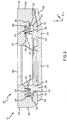
- the shroud block 210 may include a shroud main body 300 having a forward end 302 and an aft end 304 that is located aft relative to the forward end 302.
- the shroud block 210 may further include a shroud forward radial portion 306 that extends radially inward from the shroud main body 300.
- the shroud block 210 may further include a shroud aft radial portion 308 that likewise extends radially inward from the shroud main body 300.
- the shroud block 210 may further include a shroud forward axial portion 310 extending axially aft from the shroud forward radial portion 306.
- the shroud forward axial portion 310 may be located at a radially inward end of the shroud forward radial portion 306.
- the shroud block 210 may further include a shroud aft axial portion 312 extending axially forward from the shroud aft radial portion 308.
- the shroud aft axial portion 312 may be located at a radially inward end of the shroud aft radial portion 308.
- the BOAS 208 may include a BOAS main body 314.
- the BOAS 208 may further include a BOAS forward radial portion 316 extending radially outward from the BOAS main body 314.
- the BOAS 208 may further include a BOAS aft radial portion 318 that likewise extends radially outward from the BOAS main body 314.
- the BOAS forward radial portion 316 may include a forward inner portion 338 that is connected to the BOAS main body 314 and extends radially outward from the BOAS main body 314.
- the BOAS forward radial portion 316 may further include a forward outer portion 340 that is connected to the forward inner portion 338 and extends radially outward from the forward inner portion 338.
- the BOAS aft radial portion 318 may include an aft inner portion 342 that is connected to the BOAS main body 314 and extends radially outward from the BOAS main body 314.
- the BOAS aft radial portion 318 may further include an aft outer portion 343 that is connected to the aft inner portion 342 and extends radially outward from the aft inner portion 342.
- the BOAS main body 314 may include a forward wing 348 that extends axially forward from the BOAS forward radial portion 316.
- the BOAS main body 314 may further include an aft wing 350 that extend axially aft from the BOAS aft radial portion 318.
- the BOAS 208 may further include a BOAS forward axial portion 320 that extends axially forward from the BOAS forward radial portion 316.
- the BOAS forward axial portion 320 may be connected to the BOAS forward radial portion 316 between the forward inner portion 338 and the forward outer portion 340.
- the BOAS 208 may further include a BOAS aft axial portion 322 that extends axially aft from the BOAS aft radial portion 318.
- the BOAS aft axial portion 322 may be connected to the BOAS aft radial portion 318 between the aft inner portion 342 and the aft outer portion 343.
- the shroud block main body 300 may extend at least from the BOAS forward radial portion 316 to the BOAS aft radial portion 318.
- the BOAS main body 314 may extend at least from the shroud forward radial portion 306 to the shroud aft radial portion 308.
- One or more bellows seal may be positioned between the shroud block 210 and the BOAS main body 314.
- a first bellows seal 324 may be located between the shroud forward radial portion 306 and the BOAS forward radial portion 316.
- the shroud forward radial portion 306 may define an aft-facing shroud face 328, and the forward outer portion 340 of the BOAS forward radial portion 316 may define a forward-facing BOAS face 332.
- the first bellows seal 324 may extend from the aft-facing shroud face 328 to the forward-facing BOAS face 332. In that regard, the first bellows seal 324 may resist radial leakage of air between the BOAS 208 and the shroud block 210.
- a second bellows seal 326 may be located between the BOAS aft radial portion 318 and the shroud aft radial portion 308.
- the shroud aft radial portion 308 may define a forward-facing shroud face 330
- the aft outer portion 343 of the BOAS aft radial portion 318 may define an aft-facing BOAS face 334.
- the second bellows seal 326 may extend from the forward-facing shroud face 330 to the aft-facing BOAS face 334. In that regard, the second bellows seal 326 may resist radial leakage of air between the BOAS 208 and the shroud block 210.
- An axial tolerance 336 may exist between the BOAS forward axial portion 320 and the shroud forward radial portion 306.
- the axial tolerance 336 may also or instead be located between the BOAS aft axial portion 322 and the shroud aft radial portion 308.
- the axial tolerance 336 may allow axial movement of the BOAS 208 relative to the shroud block 210 in the forward or aft direction.
- the axial tolerance 336 may be between 20 thousandths of an inch (20 mils, 0.51 millimeters (mm)) and 100 mils (2.5 mm), between 40 mils (1.0 mm) and 80 mils (2.0 mm), or about 60 mils (1.5 mm). Where used in this context, about refers to the stated value plus or minus 10 percent (10%) of the stated value.
- a radial gap 344 may exist between the shroud main body 300 and the BOAS aft axial portion 322 where the second bellows seal 326 is located.
- the second bellows seal 326 may have a radial distance 402 in the radial direction.
- the radial distance 402 of the second bellows seal 326 may be about the same as the radial gap 344.
- the relationship between the radial gap 344 and the radial distance 402 of the second bellows seal 326 may likewise apply to the first bellows seal 324 and its corresponding location.
- An axial gap 346 may exist between the aft outer portion 343 and the shroud aft radial portion 308 where the second bellows seal 326 is located.
- the second bellows seal 326 may have an axial distance 400 in the axial direction in response to being in a fully extended position. Stated differently, the second bellows seal 326 has the axial distance 400 in response to a lack of pressure being applied to the second bellows seal 326.
- the axial distance 400 of the second bellows seal 326 in the fully extended position may be greater than the axial gap 346.
- the axial distance 400 may be 5%, 10%, 20%, 40%, or the like greater than the axial gap 346.
- the second bellows seal 326 may be compressed between the aft-facing BOAS face 334 of the aft outer portion 343 and the forward-facing shroud face 330 of the shroud aft radial portion 308. Such compression of the second bellows seal 326 may increase the ability of the second bellows seal 326 to resist air leakage.
- the relationship between the axial gap 346 and the axial distance 400 of the second bellows seal 326 may likewise apply to the first bellows seal 324 and its corresponding location.
- the bellows seals 324, 326 may include 5 bends. However, in various embodiments, bellows seals in accordance with various embodiments may include any quantity of bends.
- the first bellows seal 324 and the second bellows seal 326 may include any of a variety of materials. With reference to FIGS. 1 and 3 , the material of the bellows seals 324, 326 may be selected based on the location of the bellows seals 324, 326 within the gas turbine engine 20. In particular, it may be desirable for the material of the bellows seals 324, 326 to have a greater temperature resistance (i.e., resist deformation at a relatively greater temperature) if located in the high pressure turbine section 54 or the high pressure compressor section 52 rather than the low pressure turbine section 46 or the low pressure compressor section 44.
- a greater temperature resistance i.e., resist deformation at a relatively greater temperature
- the bellows seals 324, 326 may include a nickel-based alloy, a cobalt-based alloy, or the like.
- a nickel-based alloy includes more nickel by weight percent (wt%) than any other single element and, where used in this context, a cobalt-based alloy includes more cobalt by wt% than any other single element.
- a compound having 40% nickel, 30% cobalt and 30% aluminum may be referred to as a nickel-based alloy.
- the bellows seals 324, 326 may include a high performance nickel-based super alloy.
- the bellows seals 324, 326 may include a cobalt-nickel-chromium-tungsten alloy.
- the bellows seals 324, 326 may include an austenitic nickel-chromium-based alloy.
- references to "one embodiment”, “an embodiment”, “various embodiments”, etc. indicate that the embodiment described may include a particular feature, structure, or characteristic, but every embodiment may not necessarily include the particular feature, structure, or characteristic. Moreover, such phrases are not necessarily referring to the same embodiment. Further, when a particular feature, structure, or characteristic is described in connection with an embodiment, it is submitted that it is within the knowledge of one skilled in the art to affect such feature, structure, or characteristic in connection with other embodiments whether or not explicitly described. After reading the description, it will be apparent to one skilled in the relevant art(s) how to implement the disclosure in alternative embodiments.
Landscapes
- Engineering & Computer Science (AREA)
- General Engineering & Computer Science (AREA)
- Mechanical Engineering (AREA)
- Turbine Rotor Nozzle Sealing (AREA)
- Chemical & Material Sciences (AREA)
- Combustion & Propulsion (AREA)
- Sealing Devices (AREA)
Applications Claiming Priority (2)
| Application Number | Priority Date | Filing Date | Title |
|---|---|---|---|
| US201762506157P | 2017-05-15 | 2017-05-15 | |
| US15/623,208 US10533446B2 (en) | 2017-05-15 | 2017-06-14 | Alternative W-seal groove arrangement |
Publications (2)
| Publication Number | Publication Date |
|---|---|
| EP3404214A1 true EP3404214A1 (fr) | 2018-11-21 |
| EP3404214B1 EP3404214B1 (fr) | 2023-03-22 |
Family
ID=62110908
Family Applications (1)
| Application Number | Title | Priority Date | Filing Date |
|---|---|---|---|
| EP18170407.3A Active EP3404214B1 (fr) | 2017-05-15 | 2018-05-02 | Agencement de joint de pointe d'aubes et moteur à turbine à gaz ayant un tel agencement |
Country Status (2)
| Country | Link |
|---|---|
| US (1) | US10533446B2 (fr) |
| EP (1) | EP3404214B1 (fr) |
Cited By (1)
| Publication number | Priority date | Publication date | Assignee | Title |
|---|---|---|---|---|
| EP4571054A1 (fr) * | 2023-12-15 | 2025-06-18 | RTX Corporation | Joint d'étanchéité à l'air externe (oas) à accouplement amélioré avec un boîtier de premier étage |
Families Citing this family (30)
| Publication number | Priority date | Publication date | Assignee | Title |
|---|---|---|---|---|
| US10392967B2 (en) * | 2017-11-13 | 2019-08-27 | General Electric Company | Compliant seal component and associated method |
| CN111188789A (zh) * | 2020-01-22 | 2020-05-22 | 西安陕鼓通风设备有限公司 | 轴端密封装置可适应机壳热变形量的离心风机 |
| US11773741B2 (en) | 2021-06-09 | 2023-10-03 | General Electric Company | Compliant shroud designs with variable stiffness |
| US12006829B1 (en) | 2023-02-16 | 2024-06-11 | General Electric Company | Seal member support system for a gas turbine engine |
| US12486779B2 (en) | 2023-03-08 | 2025-12-02 | General Electric Company | Seal support assembly for a turbine engine |
| US12372002B2 (en) | 2023-03-24 | 2025-07-29 | General Electric Company | Seal support assembly for a turbine engine |
| US12421861B2 (en) | 2023-03-24 | 2025-09-23 | General Electric Company | Seal support assembly for a turbine engine |
| US12215587B2 (en) | 2023-03-24 | 2025-02-04 | General Electric Company | Seal support assembly for a turbine engine |
| US12241375B2 (en) | 2023-03-24 | 2025-03-04 | General Electric Company | Seal support assembly for a turbine engine |
| US12595745B2 (en) | 2023-03-24 | 2026-04-07 | General Electric Company | Seal support assembly for a turbine engine |
| US12416243B2 (en) | 2023-03-24 | 2025-09-16 | General Electric Company | Seal support assembly for a turbine engine |
| US12116896B1 (en) | 2023-03-24 | 2024-10-15 | General Electric Company | Seal support assembly for a turbine engine |
| US12215588B2 (en) | 2023-03-27 | 2025-02-04 | General Electric Company | Seal assembly for a gas turbine engine |
| US12326089B2 (en) | 2023-04-24 | 2025-06-10 | General Electric Company | Seal assembly for a gas turbine engine |
| US12286906B1 (en) | 2023-12-04 | 2025-04-29 | Rolls-Royce Corporation | Locating plate for use with turbine shroud assemblies |
| US12286885B1 (en) | 2023-12-04 | 2025-04-29 | Rolls-Royce Corporation | Turbine assembly with confronting vane and turbine shroud segment |
| US12158072B1 (en) | 2023-12-04 | 2024-12-03 | Rolls-Royce Corporation | Turbine shroud segments with damping strip seals |
| US12421862B2 (en) | 2023-12-04 | 2025-09-23 | Rolls-Royce Corporation | Turbine shroud assembly with angled cooling holes |
| US12188365B1 (en) | 2023-12-04 | 2025-01-07 | Rolls-Royce Corporation | Method and apparatus for ceramic matrix composite turbine shroud assembly |
| US12241376B1 (en) | 2023-12-04 | 2025-03-04 | Rolls-Royce Corporation | Locating plate for use with turbine shroud assemblies |
| US12152499B1 (en) | 2023-12-04 | 2024-11-26 | Rolls-Royce Corporation | Turbine shroud segments with strip seal assemblies having dampened ends |
| US12421870B1 (en) | 2024-04-30 | 2025-09-23 | Rolls-Royce Corporation | Pin mounted ceramic matrix composite heat shields with impingement cooling |
| US12305525B1 (en) | 2024-05-30 | 2025-05-20 | Rolls-Royce Corporation | Turbine shroud assemblies with rod seal and strip seals |
| US12258880B1 (en) | 2024-05-30 | 2025-03-25 | Rolls-Royce Corporation | Turbine shroud assemblies with inter-segment strip seal |
| US12215593B1 (en) | 2024-05-30 | 2025-02-04 | Rolls-Royce Corporation | Turbine shroud assembly with inter-segment damping |
| US12416241B1 (en) | 2024-05-30 | 2025-09-16 | Rolls-Royce Corporation | Turbine shroud assemblies with strip seals |
| US12352176B1 (en) | 2024-05-31 | 2025-07-08 | Rolls-Royce Corporation | Turbine shroud assemblies with channels for buffer cavity seal thermal management |
| US12410725B1 (en) | 2024-05-31 | 2025-09-09 | Rolls-Royce Corporation | Turbine shroud assemblies with air activated pistons for biasing buffer cavity seals |
| US12577881B2 (en) | 2024-05-31 | 2026-03-17 | Rolls-Royce Corporation | Turbine shroud assemblies with anti-migration seals |
| US12228044B1 (en) | 2024-06-26 | 2025-02-18 | Rolls-Royce Corporation | Turbine shroud system with ceramic matrix composite segments and dual inter-segment seals |
Citations (5)
| Publication number | Priority date | Publication date | Assignee | Title |
|---|---|---|---|---|
| US5048288A (en) * | 1988-12-20 | 1991-09-17 | United Technologies Corporation | Combined turbine stator cooling and turbine tip clearance control |
| US5423659A (en) * | 1994-04-28 | 1995-06-13 | United Technologies Corporation | Shroud segment having a cut-back retaining hook |
| US6352267B1 (en) * | 1999-03-12 | 2002-03-05 | John E. Rode | Adjustaby sizeable ring seal |
| US20160003080A1 (en) * | 2013-02-20 | 2016-01-07 | United Technologies Corporation | Gas turbine engine seal assembly |
| US20170114670A1 (en) * | 2014-06-12 | 2017-04-27 | General Electric Company | Multi-piece shroud hanger assembly |
Family Cites Families (13)
| Publication number | Priority date | Publication date | Assignee | Title |
|---|---|---|---|---|
| US4573866A (en) * | 1983-05-02 | 1986-03-04 | United Technologies Corporation | Sealed shroud for rotating body |
| US4642024A (en) * | 1984-12-05 | 1987-02-10 | United Technologies Corporation | Coolable stator assembly for a rotary machine |
| US5738490A (en) | 1996-05-20 | 1998-04-14 | Pratt & Whitney Canada, Inc. | Gas turbine engine shroud seals |
| US7207771B2 (en) * | 2004-10-15 | 2007-04-24 | Pratt & Whitney Canada Corp. | Turbine shroud segment seal |
| US7600967B2 (en) * | 2005-07-30 | 2009-10-13 | United Technologies Corporation | Stator assembly, module and method for forming a rotary machine |
| US8079807B2 (en) | 2010-01-29 | 2011-12-20 | General Electric Company | Mounting apparatus for low-ductility turbine shroud |
| US8926270B2 (en) * | 2010-12-17 | 2015-01-06 | General Electric Company | Low-ductility turbine shroud flowpath and mounting arrangement therefor |
| US9175579B2 (en) * | 2011-12-15 | 2015-11-03 | General Electric Company | Low-ductility turbine shroud |
| FR3003301B1 (fr) | 2013-03-14 | 2018-01-05 | Safran Helicopter Engines | Anneau de turbine pour turbomachine |
| EP3105421A4 (fr) * | 2014-01-23 | 2017-12-27 | United Technologies Corporation | Joint d'étanchéité à l'air adaptable avec couche maxmet à coefficient de frottement réduit |
| CA2924855A1 (fr) * | 2015-04-29 | 2016-10-29 | Rolls-Royce Corporation | Sillage de pale a distorsion trapezoidale |
| US10184352B2 (en) * | 2015-06-29 | 2019-01-22 | Rolls-Royce North American Technologies Inc. | Turbine shroud segment with integrated cooling air distribution system |
| US10385716B2 (en) | 2015-07-02 | 2019-08-20 | Unted Technologies Corporation | Seal for a gas turbine engine |
-
2017
- 2017-06-14 US US15/623,208 patent/US10533446B2/en active Active
-
2018
- 2018-05-02 EP EP18170407.3A patent/EP3404214B1/fr active Active
Patent Citations (5)
| Publication number | Priority date | Publication date | Assignee | Title |
|---|---|---|---|---|
| US5048288A (en) * | 1988-12-20 | 1991-09-17 | United Technologies Corporation | Combined turbine stator cooling and turbine tip clearance control |
| US5423659A (en) * | 1994-04-28 | 1995-06-13 | United Technologies Corporation | Shroud segment having a cut-back retaining hook |
| US6352267B1 (en) * | 1999-03-12 | 2002-03-05 | John E. Rode | Adjustaby sizeable ring seal |
| US20160003080A1 (en) * | 2013-02-20 | 2016-01-07 | United Technologies Corporation | Gas turbine engine seal assembly |
| US20170114670A1 (en) * | 2014-06-12 | 2017-04-27 | General Electric Company | Multi-piece shroud hanger assembly |
Cited By (2)
| Publication number | Priority date | Publication date | Assignee | Title |
|---|---|---|---|---|
| EP4571054A1 (fr) * | 2023-12-15 | 2025-06-18 | RTX Corporation | Joint d'étanchéité à l'air externe (oas) à accouplement amélioré avec un boîtier de premier étage |
| US12473837B2 (en) | 2023-12-15 | 2025-11-18 | Rtx Corporation | Outer air seal (OAS) with improved mating with first stage casing |
Also Published As
| Publication number | Publication date |
|---|---|
| US20180328214A1 (en) | 2018-11-15 |
| US10533446B2 (en) | 2020-01-14 |
| EP3404214B1 (fr) | 2023-03-22 |
Similar Documents
| Publication | Publication Date | Title |
|---|---|---|
| US10533446B2 (en) | Alternative W-seal groove arrangement | |
| US10344612B2 (en) | Compact advanced passive tip clearance control | |
| US10018062B2 (en) | Axial transfer tube | |
| WO2014051658A1 (fr) | Ensemble joint pour une structure statique d'un moteur à turbine à gaz | |
| US10018066B2 (en) | Mini blind stator leakage reduction | |
| EP3447249B1 (fr) | Configurations d'étanchéité avec des caractéristiques de refroidissement actif | |
| EP3051072A1 (fr) | Module de profil aérodynamique | |
| EP3546700A1 (fr) | Panier à double alésage | |
| EP3244014B1 (fr) | Ensemble de bague de retenue pour moteur à turbine à gaz | |
| EP3112615A1 (fr) | Aube de stator en porte-à-faux et un ensemble stator pour une machine rotative | |
| EP3081748B1 (fr) | Système de turbine à gaz ayant une bague d'étanchéité | |
| EP3553278B1 (fr) | Nervures de renfort axial/ailettes d'augmentation | |
| EP3112602B1 (fr) | Système de rodage d'espacement et contrôle de fuite | |
| US11408300B2 (en) | Rotor overspeed protection assembly | |
| EP3101228B1 (fr) | Déflecteur de division d'écoulement | |
| EP3309361A1 (fr) | Joint, section de moteur et moteur à turbine à gaz associés | |
| EP3101232A1 (fr) | Disque rotorique, agencement et moteur à turbine à gaz associés | |
| EP3453836B1 (fr) | Support d'aube de stator présentant des caractéristiques anti-rotation |
Legal Events
| Date | Code | Title | Description |
|---|---|---|---|
| PUAI | Public reference made under article 153(3) epc to a published international application that has entered the european phase |
Free format text: ORIGINAL CODE: 0009012 |
|
| STAA | Information on the status of an ep patent application or granted ep patent |
Free format text: STATUS: THE APPLICATION HAS BEEN PUBLISHED |
|
| AK | Designated contracting states |
Kind code of ref document: A1 Designated state(s): AL AT BE BG CH CY CZ DE DK EE ES FI FR GB GR HR HU IE IS IT LI LT LU LV MC MK MT NL NO PL PT RO RS SE SI SK SM TR |
|
| AX | Request for extension of the european patent |
Extension state: BA ME |
|
| STAA | Information on the status of an ep patent application or granted ep patent |
Free format text: STATUS: REQUEST FOR EXAMINATION WAS MADE |
|
| 17P | Request for examination filed |
Effective date: 20190521 |
|
| RBV | Designated contracting states (corrected) |
Designated state(s): AL AT BE BG CH CY CZ DE DK EE ES FI FR GB GR HR HU IE IS IT LI LT LU LV MC MK MT NL NO PL PT RO RS SE SI SK SM TR |
|
| STAA | Information on the status of an ep patent application or granted ep patent |
Free format text: STATUS: EXAMINATION IS IN PROGRESS |
|
| 17Q | First examination report despatched |
Effective date: 20210204 |
|
| RAP1 | Party data changed (applicant data changed or rights of an application transferred) |
Owner name: RAYTHEON TECHNOLOGIES CORPORATION |
|
| GRAP | Despatch of communication of intention to grant a patent |
Free format text: ORIGINAL CODE: EPIDOSNIGR1 |
|
| STAA | Information on the status of an ep patent application or granted ep patent |
Free format text: STATUS: GRANT OF PATENT IS INTENDED |
|
| INTG | Intention to grant announced |
Effective date: 20221005 |
|
| GRAS | Grant fee paid |
Free format text: ORIGINAL CODE: EPIDOSNIGR3 |
|
| GRAA | (expected) grant |
Free format text: ORIGINAL CODE: 0009210 |
|
| STAA | Information on the status of an ep patent application or granted ep patent |
Free format text: STATUS: THE PATENT HAS BEEN GRANTED |
|
| AK | Designated contracting states |
Kind code of ref document: B1 Designated state(s): AL AT BE BG CH CY CZ DE DK EE ES FI FR GB GR HR HU IE IS IT LI LT LU LV MC MK MT NL NO PL PT RO RS SE SI SK SM TR |
|
| REG | Reference to a national code |
Ref country code: GB Ref legal event code: FG4D |
|
| REG | Reference to a national code |
Ref country code: CH Ref legal event code: EP |
|
| REG | Reference to a national code |
Ref country code: IE Ref legal event code: FG4D |
|
| REG | Reference to a national code |
Ref country code: DE Ref legal event code: R096 Ref document number: 602018047409 Country of ref document: DE |
|
| REG | Reference to a national code |
Ref country code: AT Ref legal event code: REF Ref document number: 1555403 Country of ref document: AT Kind code of ref document: T Effective date: 20230415 |
|
| P01 | Opt-out of the competence of the unified patent court (upc) registered |
Effective date: 20230521 |
|
| REG | Reference to a national code |
Ref country code: LT Ref legal event code: MG9D |
|
| REG | Reference to a national code |
Ref country code: NL Ref legal event code: MP Effective date: 20230322 |
|
| PG25 | Lapsed in a contracting state [announced via postgrant information from national office to epo] |
Ref country code: RS Free format text: LAPSE BECAUSE OF FAILURE TO SUBMIT A TRANSLATION OF THE DESCRIPTION OR TO PAY THE FEE WITHIN THE PRESCRIBED TIME-LIMIT Effective date: 20230322 Ref country code: NO Free format text: LAPSE BECAUSE OF FAILURE TO SUBMIT A TRANSLATION OF THE DESCRIPTION OR TO PAY THE FEE WITHIN THE PRESCRIBED TIME-LIMIT Effective date: 20230622 Ref country code: LV Free format text: LAPSE BECAUSE OF FAILURE TO SUBMIT A TRANSLATION OF THE DESCRIPTION OR TO PAY THE FEE WITHIN THE PRESCRIBED TIME-LIMIT Effective date: 20230322 Ref country code: LT Free format text: LAPSE BECAUSE OF FAILURE TO SUBMIT A TRANSLATION OF THE DESCRIPTION OR TO PAY THE FEE WITHIN THE PRESCRIBED TIME-LIMIT Effective date: 20230322 Ref country code: HR Free format text: LAPSE BECAUSE OF FAILURE TO SUBMIT A TRANSLATION OF THE DESCRIPTION OR TO PAY THE FEE WITHIN THE PRESCRIBED TIME-LIMIT Effective date: 20230322 |
|
| REG | Reference to a national code |
Ref country code: AT Ref legal event code: MK05 Ref document number: 1555403 Country of ref document: AT Kind code of ref document: T Effective date: 20230322 |
|
| PG25 | Lapsed in a contracting state [announced via postgrant information from national office to epo] |
Ref country code: SE Free format text: LAPSE BECAUSE OF FAILURE TO SUBMIT A TRANSLATION OF THE DESCRIPTION OR TO PAY THE FEE WITHIN THE PRESCRIBED TIME-LIMIT Effective date: 20230322 Ref country code: NL Free format text: LAPSE BECAUSE OF FAILURE TO SUBMIT A TRANSLATION OF THE DESCRIPTION OR TO PAY THE FEE WITHIN THE PRESCRIBED TIME-LIMIT Effective date: 20230322 Ref country code: GR Free format text: LAPSE BECAUSE OF FAILURE TO SUBMIT A TRANSLATION OF THE DESCRIPTION OR TO PAY THE FEE WITHIN THE PRESCRIBED TIME-LIMIT Effective date: 20230623 Ref country code: FI Free format text: LAPSE BECAUSE OF FAILURE TO SUBMIT A TRANSLATION OF THE DESCRIPTION OR TO PAY THE FEE WITHIN THE PRESCRIBED TIME-LIMIT Effective date: 20230322 |
|
| PG25 | Lapsed in a contracting state [announced via postgrant information from national office to epo] |
Ref country code: SM Free format text: LAPSE BECAUSE OF FAILURE TO SUBMIT A TRANSLATION OF THE DESCRIPTION OR TO PAY THE FEE WITHIN THE PRESCRIBED TIME-LIMIT Effective date: 20230322 Ref country code: RO Free format text: LAPSE BECAUSE OF FAILURE TO SUBMIT A TRANSLATION OF THE DESCRIPTION OR TO PAY THE FEE WITHIN THE PRESCRIBED TIME-LIMIT Effective date: 20230322 Ref country code: PT Free format text: LAPSE BECAUSE OF FAILURE TO SUBMIT A TRANSLATION OF THE DESCRIPTION OR TO PAY THE FEE WITHIN THE PRESCRIBED TIME-LIMIT Effective date: 20230724 Ref country code: ES Free format text: LAPSE BECAUSE OF FAILURE TO SUBMIT A TRANSLATION OF THE DESCRIPTION OR TO PAY THE FEE WITHIN THE PRESCRIBED TIME-LIMIT Effective date: 20230322 Ref country code: EE Free format text: LAPSE BECAUSE OF FAILURE TO SUBMIT A TRANSLATION OF THE DESCRIPTION OR TO PAY THE FEE WITHIN THE PRESCRIBED TIME-LIMIT Effective date: 20230322 Ref country code: AT Free format text: LAPSE BECAUSE OF FAILURE TO SUBMIT A TRANSLATION OF THE DESCRIPTION OR TO PAY THE FEE WITHIN THE PRESCRIBED TIME-LIMIT Effective date: 20230322 |
|
| RAP4 | Party data changed (patent owner data changed or rights of a patent transferred) |
Owner name: RTX CORPORATION |
|
| PG25 | Lapsed in a contracting state [announced via postgrant information from national office to epo] |
Ref country code: SK Free format text: LAPSE BECAUSE OF FAILURE TO SUBMIT A TRANSLATION OF THE DESCRIPTION OR TO PAY THE FEE WITHIN THE PRESCRIBED TIME-LIMIT Effective date: 20230322 Ref country code: PL Free format text: LAPSE BECAUSE OF FAILURE TO SUBMIT A TRANSLATION OF THE DESCRIPTION OR TO PAY THE FEE WITHIN THE PRESCRIBED TIME-LIMIT Effective date: 20230322 Ref country code: IS Free format text: LAPSE BECAUSE OF FAILURE TO SUBMIT A TRANSLATION OF THE DESCRIPTION OR TO PAY THE FEE WITHIN THE PRESCRIBED TIME-LIMIT Effective date: 20230722 |
|
| REG | Reference to a national code |
Ref country code: CH Ref legal event code: PL |
|
| REG | Reference to a national code |
Ref country code: DE Ref legal event code: R097 Ref document number: 602018047409 Country of ref document: DE |
|
| PG25 | Lapsed in a contracting state [announced via postgrant information from national office to epo] |
Ref country code: MC Free format text: LAPSE BECAUSE OF FAILURE TO SUBMIT A TRANSLATION OF THE DESCRIPTION OR TO PAY THE FEE WITHIN THE PRESCRIBED TIME-LIMIT Effective date: 20230322 |
|
| PLBE | No opposition filed within time limit |
Free format text: ORIGINAL CODE: 0009261 |
|
| STAA | Information on the status of an ep patent application or granted ep patent |
Free format text: STATUS: NO OPPOSITION FILED WITHIN TIME LIMIT |
|
| REG | Reference to a national code |
Ref country code: BE Ref legal event code: MM Effective date: 20230531 |
|
| PG25 | Lapsed in a contracting state [announced via postgrant information from national office to epo] |
Ref country code: SI Free format text: LAPSE BECAUSE OF FAILURE TO SUBMIT A TRANSLATION OF THE DESCRIPTION OR TO PAY THE FEE WITHIN THE PRESCRIBED TIME-LIMIT Effective date: 20230322 Ref country code: MC Free format text: LAPSE BECAUSE OF FAILURE TO SUBMIT A TRANSLATION OF THE DESCRIPTION OR TO PAY THE FEE WITHIN THE PRESCRIBED TIME-LIMIT Effective date: 20230322 Ref country code: LU Free format text: LAPSE BECAUSE OF NON-PAYMENT OF DUE FEES Effective date: 20230502 Ref country code: LI Free format text: LAPSE BECAUSE OF NON-PAYMENT OF DUE FEES Effective date: 20230531 Ref country code: DK Free format text: LAPSE BECAUSE OF FAILURE TO SUBMIT A TRANSLATION OF THE DESCRIPTION OR TO PAY THE FEE WITHIN THE PRESCRIBED TIME-LIMIT Effective date: 20230322 Ref country code: CZ Free format text: LAPSE BECAUSE OF FAILURE TO SUBMIT A TRANSLATION OF THE DESCRIPTION OR TO PAY THE FEE WITHIN THE PRESCRIBED TIME-LIMIT Effective date: 20230322 Ref country code: CH Free format text: LAPSE BECAUSE OF NON-PAYMENT OF DUE FEES Effective date: 20230531 |
|
| 26N | No opposition filed |
Effective date: 20240102 |
|
| REG | Reference to a national code |
Ref country code: IE Ref legal event code: MM4A |
|
| PG25 | Lapsed in a contracting state [announced via postgrant information from national office to epo] |
Ref country code: IE Free format text: LAPSE BECAUSE OF NON-PAYMENT OF DUE FEES Effective date: 20230502 |
|
| PG25 | Lapsed in a contracting state [announced via postgrant information from national office to epo] |
Ref country code: IE Free format text: LAPSE BECAUSE OF NON-PAYMENT OF DUE FEES Effective date: 20230502 |
|
| PG25 | Lapsed in a contracting state [announced via postgrant information from national office to epo] |
Ref country code: IT Free format text: LAPSE BECAUSE OF FAILURE TO SUBMIT A TRANSLATION OF THE DESCRIPTION OR TO PAY THE FEE WITHIN THE PRESCRIBED TIME-LIMIT Effective date: 20230322 Ref country code: BE Free format text: LAPSE BECAUSE OF NON-PAYMENT OF DUE FEES Effective date: 20230531 |
|
| PG25 | Lapsed in a contracting state [announced via postgrant information from national office to epo] |
Ref country code: BG Free format text: LAPSE BECAUSE OF FAILURE TO SUBMIT A TRANSLATION OF THE DESCRIPTION OR TO PAY THE FEE WITHIN THE PRESCRIBED TIME-LIMIT Effective date: 20230322 |
|
| PG25 | Lapsed in a contracting state [announced via postgrant information from national office to epo] |
Ref country code: BG Free format text: LAPSE BECAUSE OF FAILURE TO SUBMIT A TRANSLATION OF THE DESCRIPTION OR TO PAY THE FEE WITHIN THE PRESCRIBED TIME-LIMIT Effective date: 20230322 |
|
| PGFP | Annual fee paid to national office [announced via postgrant information from national office to epo] |
Ref country code: DE Payment date: 20250423 Year of fee payment: 8 |
|
| PGFP | Annual fee paid to national office [announced via postgrant information from national office to epo] |
Ref country code: GB Payment date: 20250423 Year of fee payment: 8 |
|
| PGFP | Annual fee paid to national office [announced via postgrant information from national office to epo] |
Ref country code: FR Payment date: 20250423 Year of fee payment: 8 |
|
| PG25 | Lapsed in a contracting state [announced via postgrant information from national office to epo] |
Ref country code: CY Free format text: LAPSE BECAUSE OF FAILURE TO SUBMIT A TRANSLATION OF THE DESCRIPTION OR TO PAY THE FEE WITHIN THE PRESCRIBED TIME-LIMIT; INVALID AB INITIO Effective date: 20180502 |
|
| PG25 | Lapsed in a contracting state [announced via postgrant information from national office to epo] |
Ref country code: HU Free format text: LAPSE BECAUSE OF FAILURE TO SUBMIT A TRANSLATION OF THE DESCRIPTION OR TO PAY THE FEE WITHIN THE PRESCRIBED TIME-LIMIT; INVALID AB INITIO Effective date: 20180502 |
|
| REG | Reference to a national code |
Ref country code: DE Ref legal event code: R081 Ref document number: 602018047409 Country of ref document: DE Owner name: RTX CORPORATION (N.D.GES.D. STAATES DELAWARE),, US Free format text: FORMER OWNER: RAYTHEON TECHNOLOGIES CORPORATION, FARMINGTON, CT, US |
|
| PG25 | Lapsed in a contracting state [announced via postgrant information from national office to epo] |
Ref country code: TR Free format text: LAPSE BECAUSE OF FAILURE TO SUBMIT A TRANSLATION OF THE DESCRIPTION OR TO PAY THE FEE WITHIN THE PRESCRIBED TIME-LIMIT Effective date: 20230322 |