EP3404221A1 - Appareil de service de turbomachine et procédé associé - Google Patents
Appareil de service de turbomachine et procédé associé Download PDFInfo
- Publication number
- EP3404221A1 EP3404221A1 EP18171493.2A EP18171493A EP3404221A1 EP 3404221 A1 EP3404221 A1 EP 3404221A1 EP 18171493 A EP18171493 A EP 18171493A EP 3404221 A1 EP3404221 A1 EP 3404221A1
- Authority
- EP
- European Patent Office
- Prior art keywords
- threaded fastener
- threaded
- tensioning device
- tensioner
- tensioning
- Prior art date
- Legal status (The legal status is an assumption and is not a legal conclusion. Google has not performed a legal analysis and makes no representation as to the accuracy of the status listed.)
- Granted
Links
Images


Classifications
-
- B—PERFORMING OPERATIONS; TRANSPORTING
- B23—MACHINE TOOLS; METAL-WORKING NOT OTHERWISE PROVIDED FOR
- B23P—METAL-WORKING NOT OTHERWISE PROVIDED FOR; COMBINED OPERATIONS; UNIVERSAL MACHINE TOOLS
- B23P19/00—Machines for simply fitting together or separating metal parts or objects, or metal and non-metal parts, whether or not involving some deformation; Tools or devices therefor so far as not provided for in other classes
- B23P19/04—Machines for simply fitting together or separating metal parts or objects, or metal and non-metal parts, whether or not involving some deformation; Tools or devices therefor so far as not provided for in other classes for assembling or disassembling parts
- B23P19/06—Screw or nut setting or loosening machines
- B23P19/067—Bolt tensioners
-
- B—PERFORMING OPERATIONS; TRANSPORTING
- B25—HAND TOOLS; PORTABLE POWER-DRIVEN TOOLS; MANIPULATORS
- B25B—TOOLS OR BENCH DEVICES NOT OTHERWISE PROVIDED FOR, FOR FASTENING, CONNECTING, DISENGAGING OR HOLDING
- B25B23/00—Details of, or accessories for, spanners, wrenches, screwdrivers
- B25B23/0085—Counterholding devices
-
- B—PERFORMING OPERATIONS; TRANSPORTING
- B25—HAND TOOLS; PORTABLE POWER-DRIVEN TOOLS; MANIPULATORS
- B25B—TOOLS OR BENCH DEVICES NOT OTHERWISE PROVIDED FOR, FOR FASTENING, CONNECTING, DISENGAGING OR HOLDING
- B25B29/00—Accessories
- B25B29/02—Bolt tensioners
-
- F—MECHANICAL ENGINEERING; LIGHTING; HEATING; WEAPONS; BLASTING
- F01—MACHINES OR ENGINES IN GENERAL; ENGINE PLANTS IN GENERAL; STEAM ENGINES
- F01D—NON-POSITIVE DISPLACEMENT MACHINES OR ENGINES, e.g. STEAM TURBINES
- F01D25/00—Component parts, details, or accessories, not provided for in, or of interest apart from, other groups
- F01D25/24—Casings; Casing parts, e.g. diaphragms, casing fastenings
- F01D25/243—Flange connections; Bolting arrangements
-
- F—MECHANICAL ENGINEERING; LIGHTING; HEATING; WEAPONS; BLASTING
- F16—ENGINEERING ELEMENTS AND UNITS; GENERAL MEASURES FOR PRODUCING AND MAINTAINING EFFECTIVE FUNCTIONING OF MACHINES OR INSTALLATIONS; THERMAL INSULATION IN GENERAL
- F16B—DEVICES FOR FASTENING OR SECURING CONSTRUCTIONAL ELEMENTS OR MACHINE PARTS TOGETHER, e.g. NAILS, BOLTS, CIRCLIPS, CLAMPS, CLIPS OR WEDGES; JOINTS OR JOINTING
- F16B31/00—Screwed connections specially modified in view of tensile load; Break-bolts
- F16B31/04—Screwed connections specially modified in view of tensile load; Break-bolts for maintaining a tensile load
- F16B31/043—Prestressed connections tensioned by means of liquid, grease, rubber, explosive charge, or the like
-
- F—MECHANICAL ENGINEERING; LIGHTING; HEATING; WEAPONS; BLASTING
- F05—INDEXING SCHEMES RELATING TO ENGINES OR PUMPS IN VARIOUS SUBCLASSES OF CLASSES F01-F04
- F05D—INDEXING SCHEME FOR ASPECTS RELATING TO NON-POSITIVE-DISPLACEMENT MACHINES OR ENGINES, GAS-TURBINES OR JET-PROPULSION PLANTS
- F05D2230/00—Manufacture
- F05D2230/60—Assembly methods
-
- F—MECHANICAL ENGINEERING; LIGHTING; HEATING; WEAPONS; BLASTING
- F05—INDEXING SCHEMES RELATING TO ENGINES OR PUMPS IN VARIOUS SUBCLASSES OF CLASSES F01-F04
- F05D—INDEXING SCHEME FOR ASPECTS RELATING TO NON-POSITIVE-DISPLACEMENT MACHINES OR ENGINES, GAS-TURBINES OR JET-PROPULSION PLANTS
- F05D2230/00—Manufacture
- F05D2230/70—Disassembly methods
-
- F—MECHANICAL ENGINEERING; LIGHTING; HEATING; WEAPONS; BLASTING
- F05—INDEXING SCHEMES RELATING TO ENGINES OR PUMPS IN VARIOUS SUBCLASSES OF CLASSES F01-F04
- F05D—INDEXING SCHEME FOR ASPECTS RELATING TO NON-POSITIVE-DISPLACEMENT MACHINES OR ENGINES, GAS-TURBINES OR JET-PROPULSION PLANTS
- F05D2230/00—Manufacture
- F05D2230/72—Maintenance
Definitions
- turbomachines More particularly, the subject matter disclosed herein relates to service apparatuses and methods for servicing turbomachines, e.g., gas turbomachines.
- Gas turbomachines also referred to as gas turbines
- gas turbines include internal sections or chambers, including a compression chamber, a combustion chamber and a turbine section, surrounded by a casing (or shell).
- the casing is conventionally composed of segments which are bolted together at one or more interfaces.
- servicing e.g., installation, repair, maintenance
- the weight of these individual segments, as well as the overall weight of the turbomachine can place significant tension on the bolts (or, threaded fasteners) which hold the casing together.
- an apparatus includes: a system for servicing a turbomachine casing having adjacent segments joined with a set of threaded fasteners, the system including: a threaded fastener tensioning device sized to fit over ends of a threaded fastener in the set of threaded fasteners, the threaded fastener tensioning device including: a retention component for retaining a first end of the threaded fastener; and a tensioner for tensioning or de-tensioning a second end of the threaded fastener; and a mounting system coupled with the threaded fastener tensioning device, the mounting system for retaining the threaded fastener tensioning device proximate the adjacent segments of the turbomachine casing.
- a second aspect of the disclosure includes a method of servicing a turbomachine casing having adjacent segments joined with a set of threaded fasteners, the method including: coupling a service system with a threaded fastener in the set of threaded fasteners, the service system having: a threaded fastener tensioning device sized to fit over ends of the threaded fastener, the threaded fastener tensioning device including: a retention component for retaining a first end of the threaded fastener; and a tensioner for tensioning or de-tensioning a second end of the threaded fastener; and a mounting system coupled with the threaded fastener tensioning device, the mounting system for retaining the threaded fastener tensioning device proximate the adjacent segments of the turbomachine casing; and actuating the threaded fastener tensioner to tension or de-tension the second end of the threaded fastener.
- the subject matter disclosed relates to gas turbomachines. More particularly, the subject matter disclosed herein relates to service apparatuses and methods for servicing gas turbomachine casings.
- the threaded fastener mechanism includes a threaded stud with a flat nut on each end used to fasten the casing sections together.
- the threaded fastener mechanism is placed into tension, rather than torqued, to achieve the desired applied load for coupling the casing sections (e.g., approximately 60 kilo-pounds/square inch, or approximately 415 Mega-Pascals).
- a system is configured for servicing a gas turbomachine (GT) casing.
- the system can include a threaded fastener tensioning device for tensioning/de-tensioning the threaded fasteners on the GT casing, and a mounting system for affixing the threaded fastener tensioning device in position relative to the GT casing.
- the threaded fasteners (including a threaded stud and complementary nut) can be pre-loaded (or threaded) to couple adjacent sections of the GT casing.
- the threaded fastener tensioning device can include a retention component and a tensioning/de-tensioning device for placing tension on, or removing tension from, the nuts on the end of the threaded studs after the threaded fasteners are loaded to initially couple the adjacent sections of the GT casing.
- the threaded fastener tensioning device can include a set of actuatable handles for use by an operator (e.g., a human operator) to tension/de-tension the nuts and ease the process of coupling/decoupling sections of the GT casing.
- the mounting system can include an overhead lift or gantry system, and in some particular cases, the mounting system can include a pneumatic lifting device.
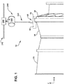
- FIG. 1 shows a schematic depiction of a system 10 for servicing a turbomachine casing 20 according to various embodiments of the disclosure.
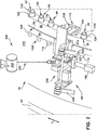
- FIGS. 2 and 3 show close-up perspective views of the system 10 interacting with turbomachine casing 20 according to various embodiments of the disclosure.
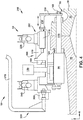
- FIG. 4 shows a schematic cross-sectional view of a portion of system 10 and turbomachine casing 20.
- FIGS. 1-4 are referred to simultaneously to illustrate various particular aspects of the disclosure.
- turbomachine casing 20 can include adjacent segments 30 (two shown) joined with a set of threaded fasteners (e.g., nut/bolt combinations) 40.
- turbomachine casing 20 can include a gas turbomachine casing, which may be joined at a horizontal or vertical joint between adjacent segments 30.
- Segments 30 can be joined according to conventional approaches, e.g., by aligning segments 30, including threaded fastener openings 50, and inserting threaded fasteners 40 in threaded fastener openings 50.
- threaded fasteners 40 can be pre-loaded, or threaded, to couple segments 30 together, prior to performing processes according to various embodiments described herein.
- system 10 can include a threaded fastener tensioning device 60 sized to fit over a threaded fastener 40 (in the set of threaded fasteners 40) after that fastener has been placed in openings 50 and initially loaded (or threaded).
- Threaded fastener tensioning device 60 as described herein, can include a variety of sub-components for tensioning/de-tensioning one or more threaded fasteners 40 in the set of threaded fasteners 40.
- Threaded fastener tensioning device 60 is sized (or, configured) to fit over ends of threaded fastener 40 (along its primary axis) in order to tension/de-tension that threaded fastener 40 as described herein.
- threaded fastener tensioning device 60 can include a retention component 70 for retaining a first end 80 of threaded fastener 40, and a tensioner 90 for tensioning or de-tensioning a second end 100 of threaded fastener 40.
- Each threaded fastener 40 can include a threaded stud 110 (e.g., externally threaded stud) and a nut 120 (e.g., internally threaded nut) threadably coupled on each end 80, 100 of threaded stud 110, for holding threaded fastener 40 in place between segments 30.
- Retention component 70 is sized to restrict rotation of threaded stud 110 at first end 80 of threaded fastener 40.
- retention component 70 can include an adapter plate 130 and a coupler 140 for retaining first end 80 of threaded fastener 40.
- coupler 140 can include an interface configured to mate with first end 80 of threaded fastener 40, e.g., where first end 80 has an outer surface with a contour, edge, etc., coupler 140 can include a sleeve or slot with a complementary interface for mating with first end 80.
- first end 80 of threaded fastener 40 e.g., nut 120
- coupler 140 includes a complementary inner surface for retaining first end 80.
- coupler 140 can be configured to expand/contract to interface with first end 80 of threaded fastener 40, e.g., at nut 120).
- adapter plate 130 can be configured to lock coupler 140 in place to retain threaded fastener 40.
- Nut 120 at first end 80 can be place over threaded fastener 40 and adjusted according to various conventional approaches.
- nut 120 (having internal threads) is threaded over threaded stud 110 (having external threads) and rotated to adjust the threaded fastener 40.
- coupler 140 can include a prong 145 (or other protrusion) ( FIG.
- slot 155 can include a hexagonal-shaped or square-shaped internal slot having a plurality of faces.
- prong 145 can include a complementary number of external faces, such that prong 145 and slot 155 can mate in a male-female manner.
- coupler 140 can be configured with an internal slot for receiving a prong extending from first end 80 of stud 110. That is, other conventional male-female mating configurations could be used by coupler 140 to retain threaded fastener 40.
- Tensioner 90 can be configured to couple with second (opposite) end 100 of threaded fastener 40 (e.g., in particular threaded stud 110 and nut 120), and can include a conventional tensioning device for imparting or releasing tension on threaded fasteners (e.g., threaded fastener 40).
- Tensioner 90 can include a conventional hydraulic threaded fastener tensioning cylinder, such as those available from ITH Threaded fastenering Technology, of Kunststoff, Germany. However, other conventional tensioning devices and/or tensioning cylinders can be utilized according to various aspects of the disclosure.
- Tensioner 90 can include an integrated hydraulic system, or can be coupled with a hydraulic system 150 on threaded fastener tensioning device 60 or an external hydraulic system, as is known in the art.
- the tensioning/de-tensioning process can include mounting tensioner 90 onto nut 120 at second end 100 of threaded fastener 40.
- the tensioner 90 can include a hydraulic threaded fastener tensioning cylinder, which can be threaded onto threaded fastener 40 at second end 100 according to various embodiments. After mounting tensioner 90, hydraulic pressure can be applied through the tensioner 90, e.g., via actuation of a handle, as described herein.
- wrenching system 160 can include one or more motors 170 coupled with an actuator 180 ( FIG. 4 ) for initiating tightening/loosening of nut 120 on threaded stud 110.
- wrenching system 160 includes a set of gears for initiating actuator 180 to tighten/loosen nut 120.
- wrenching system 160 can be actuated using a lever 190 ( FIG. 3 ) coupled with motor 170.
- coupler 140 can be configured to retain stud 110 at first end 80 during the tensioning process.
- threaded fastener tensioning device 60 can further include an adapter 200 connected with retention component 70 and tensioner 90 for modifying a position of retention component 70 relative to tensioner 90 in order engage or disengage threaded fastener 40.
- adapter 200 can include an actuatable cylinder 210 connected with retention component 70, and a handle 220 coupled with actuatable cylinder 210 for modifying a position of retention component 70 relative to tensioner 90, e.g., axially toward or away from tensioner 90.
- actuatable cylinder 210 can include a pneumatic or hydraulic cylinder connected with adapter plate 130, e.g., via an extension member 230 (example embodiment illustrated in FIG. 4 ).
- Handle 220 can be actuatable by an operator (e.g., human and/or robotic user) to initiate flow of pneumatic or hydraulic fluid in actuatable cylinder 210, and move adapter 200 (e.g., extension member 230 and/or adapter plate 130).
- threaded fastener tensioning device 60 can also include a second handle 240 coupled with tensioner 90 for initiating tensioning or de-tensioning of second end 100 of threaded fastener 40.
- tensioner 90 can include handle 240 which allows an operator (e.g., human and/or robotic user) to actuate tensioner 90 and tension/de-tension threaded fastener 40.
- second handle 240 and (first) handle 220 are accessible from a same side (or, top side) 250 of threaded fastener tensioning device 60 to allow the operator to effectively control both tensioner 90 and adapter 200 during a service operation.
- handle 240 and/or handle 220 can take the form of any actuatable arm, lever, or other member which can be rotated, flipped, or otherwise manipulated to perform functions described herein.
- system 10 can further include a mounting system 260 coupled with threaded fastener tensioning device 60.
- Mounting system 260 can be configured to retain threaded fastener tensioning device 60 proximate segments 30 of casing 20.
- mounting system 260 can include a mounting arm 270 coupled with threaded fastener tensioning device 60 for coupling with an external mounting structure, e.g., a crane system, gantry system, robotic arm, or lift.
- mounting arm 270 can be coupled with an overhead crane 280 and/or gantry system 290 ( FIGS. 1 and 2 ) for modifying a position of threaded fastener tensioning device 60 relative to casing 20.
- an overhead crane 280 can include a pneumatic or hydraulic lifting system for moving threaded fastener tensioning device 260 according to various control commands.
- overhead crane 280 can be mounted or otherwise coupled with gantry system 290, which may be mounted to a ceiling or overhead surface 310 (only a portion shown in FIG. 1 ).
- overhead crane 280 can include a line 320 for coupling with threaded fastener tensioning device 60 (e.g., a retractable/extendable line 320) to enable movement of threaded fastener tensioning device in the radial direction.
- mounting system 260 can include any additional conventional mounting system(s), including a direct mounting system (e.g., connecting directly to casing 20), and/or a floor-based mounting system (e.g., supported in some manner by a common surface which supports casing 20).
- overhead crane 280 and/or gantry system 290 can be controlled by a control system and/or a human or robotic operator, to modify the position of threaded fastener tensioning device 60 relative to casing 20, e.g., moving threaded fastener tensioning device 60 axially (direction A), laterally (direction L) and/or radially (direction r) to adjust one or more threaded fasteners 40 on casing 20 ( FIGS.
- mounting system 260 can further include a rotatable retention component 300 between mounting arm 270 and threaded fastener tensioning device 60 for permitting movement of mounting arm 270 relative to threaded fastener tensioning device 60.
- This rotatable retention component 300 can allow the threaded fastener tensioning device 60 to adjust a plurality of threaded fasteners 40 along the arced interface of casing 20 without requiring movement (e.g., rotation) of casing 20.
- rotatable retention component 300 can include a locking mechanism for locking threaded fastener tensioning device 60 along a range of angles relative to mounting arm 270 (which remains substantially vertically aligned).
- a method of servicing turbomachine casing 20 can be performed according to processes outlined in the flow diagram of FIG. 5 . These processes are described with continuing reference to FIGS. 1-4 . As shown, these processes can include:
- Process P0 (optional pre-process in various embodiments): Adjusting mounting system 260 to position threaded fastener tensioning device 60 proximate threaded fastener 40. In some cases, this can include instructing mounting system 260 to move axially (direction A), laterally (direction L) and/or radially (direction r) in order to position threaded fastener tensioning device 60 proximate a threaded fastener 40 to be serviced. In some cases, an operator can manually control mounting system 260, e.g., via a controller for overhead crane 280 and/or gantry 290.
- overhead crane 280 and/or gantry 290 can include a conventional control system with programmable software for programming instructions to modify a position of a device coupled to the mounting system 260 (e.g., threaded fastener tensioning device 60).
- the programmable software may be configured to instruct overhead crane 280 and/or gantry 290 to move according to a prescribed pattern or set of inputs to position/reposition threaded fastener tensioning device 60 relative to casing 20.
- Other control scenarios known in the art could also be employed to position/reposition threaded fastener tensioning device 60 relative to casing 20.
- coupling service system 10 with a threaded fastener 40 in the set of threaded fasteners 40 can include adjusting a position of threaded fastener tensioning device 60, e.g., by adjusting a position of retention component 70 relative to tensioner 90 in order to fit the threaded fastener tensioning device 60 over the sections 30 of casing 20. That is, in various embodiments, an operator can actuate handle 220 in order to move adapter 200 (e.g., extension member 230 and/or adapter plate 130) such that the space between tensioner 90 and retention component 70 is greater than the length of threaded stud 110.
- adapter 200 e.g., extension member 230 and/or adapter plate 130
- threaded fastener tensioning device 60 can fit over sections 30 of casing 20 to engage threaded fastener 40.
- operator can actuate handle 220 to move retention component 70, in order to engage first end 80 of stud 110 (with coupler 140).
- the coupling process can also include actuating lever 190 to engage motor 170 and thread tensioner 90 onto threaded fastener 40, and initiating actuator 180 to rotate the gear drive on tensioner 90. This process can align tensioner 90 with nut 120 in preparation for tensioning/de-tensioning threaded fastener 40.
- Process P1 and Process P0 could be performed substantially simultaneously, or portions of these processes could overlap in time (e.g., adapter 200 could be actuated prior to, or simultaneously with process P0).
- Process P2 (after Process P1): actuating threaded fastener tensioner 90 to tension or de-tension second end 100 of threaded fastener 40.
- an operator can actuate second handle 240 to initiate tensioner 90 in order to tension/de-tension threaded fastener 40.
- second handle 240 and (first) handle 220 are accessible from a same side (or, top side) 250 of threaded fastener tensioning device 60 to allow the operator to effectively control both tensioner 90 and adapter 200 during a service operation.
- actuating second handle 240 can initiate pressurization of threaded fastener 40 (e.g., up to approximately 20 Mega-pascal (MPa), or approximately 20,000 pounds-per-square inch (psi)).
- actuator 180 is configured to thread or un-thread stud 110 and disengage nut 120, thereby imparting or releasing tension from threaded fastener 40.
- Tensioner 90 can then release pressure, and lever 190 can be actuated to unthread tensioner 90 from threaded fastener 90.
- an operator can actuate second handle 240 during the entirety of the tensioning/de-tensioning process, until appropriate tension is applied to, or released from, threaded fastener 40.
- processes P0-P2 can be performed for a plurality of threaded fasteners 40 in a casing 20.
- additional processes can include de-coupling service system 10 from threaded fastener 40 (e.g., reversing processes P2 and P1) and coupling service system 10 to a distinct threaded fastener 40 in the set of threaded fasteners 40 (e.g., performing processes P1 and P2, and optionally process P0 for a second threaded fastener 40).
- the operator can actuate handle 220 coupled with actuatable cylinder 210 to modifying a position of retention component 70 relative to tensioner 90, thereby allowing for removal of service system 10 from threaded fastener 40.
- the processes noted here can be repeated for a plurality of threaded fasteners 40.
- service system 10 can allow for significantly increased efficiency in servicing threaded fasteners 40 in a turbomachine casing 20 relative to conventional approaches.
- conventional approaches for servicing these threaded fasteners requires a large crew of operators (e.g., up to five people), and a many-step process (e.g., greater than a dozen steps).
- the service system 10 disclosed according to various embodiments can be utilized by 1-2 operators (e.g., two human operators, a human operator and a robotic operator, or a single human or robotic operator) to effectively service threaded fasteners 40 in a turbomachine casing 20.
- the handle and lever systems shown and described according to various embodiments can significantly increase the efficiency of service operations relative to conventional approaches, and can reduce system downtime.
- processes described herein can be iterated (repeated) periodically (e.g., according to schedule of x times per y period, and/or continuously) in order to aid in servicing one more portion(s) of turbomachine casing 20, e.g., in servicing a plurality of threaded fasteners 40 extending between various segments 30 of casing 20.
- one or more of the processes described herein can be repeated, for example, for a set of components, e.g., threaded fasteners 40.
- components described as being “coupled” to one another can be joined along one or more interfaces.
- these interfaces can include junctions between distinct components, and in other cases, these interfaces can include a solidly and/or integrally formed interconnection. That is, in some cases, components that are “coupled” to one another can be simultaneously formed to define a single continuous member.
- these coupled components can be formed as separate members and be subsequently joined through known processes (e.g., soldering, fastening, ultrasonic welding, bonding).
- electronic components described as being “coupled” can be linked via conventional hard-wired and/or wireless means such that these electronic components can communicate data with one another.
Landscapes
- Engineering & Computer Science (AREA)
- Mechanical Engineering (AREA)
- General Engineering & Computer Science (AREA)
- Structures Of Non-Positive Displacement Pumps (AREA)
- Clamps And Clips (AREA)
- Hand Tools For Fitting Together And Separating, Or Other Hand Tools (AREA)
Applications Claiming Priority (1)
| Application Number | Priority Date | Filing Date | Title |
|---|---|---|---|
| US15/597,581 US10632577B2 (en) | 2017-05-17 | 2017-05-17 | Turbomachine service apparatus and related method |
Publications (2)
| Publication Number | Publication Date |
|---|---|
| EP3404221A1 true EP3404221A1 (fr) | 2018-11-21 |
| EP3404221B1 EP3404221B1 (fr) | 2020-04-08 |
Family
ID=62148181
Family Applications (1)
| Application Number | Title | Priority Date | Filing Date |
|---|---|---|---|
| EP18171493.2A Active EP3404221B1 (fr) | 2017-05-17 | 2018-05-09 | Appareil de service de turbomachine et procédé associé |
Country Status (3)
| Country | Link |
|---|---|
| US (1) | US10632577B2 (fr) |
| EP (1) | EP3404221B1 (fr) |
| JP (1) | JP7154819B2 (fr) |
Families Citing this family (4)
| Publication number | Priority date | Publication date | Assignee | Title |
|---|---|---|---|---|
| US11739664B1 (en) * | 2022-03-17 | 2023-08-29 | Pratt & Whitney Canada Corp. | Service tube locking device |
| US11702946B1 (en) | 2022-07-13 | 2023-07-18 | Pratt & Whitney Canada Corp. | Service tube locking device |
| US12012872B1 (en) | 2023-03-08 | 2024-06-18 | Pratt & Whitney Canada Corp. | Service tube locking device |
| EP4520960B1 (fr) * | 2023-09-06 | 2026-02-18 | Admede Ab | Outil d'allongement pour allonger une tige filetée ou un boulon d'un raccord à bride |
Citations (5)
| Publication number | Priority date | Publication date | Assignee | Title |
|---|---|---|---|---|
| US1607929A (en) * | 1924-12-23 | 1926-11-23 | Waters Frederick | Bolt-holding wrench |
| US2600214A (en) * | 1951-03-30 | 1952-06-10 | Frank G Davis | Adjustable bolt-holding wrench |
| DE3704202C1 (en) * | 1987-02-11 | 1988-05-05 | Daimler Benz Ag | Offset screwing tool supplied with auxiliary power |
| WO1995033598A1 (fr) * | 1994-06-07 | 1995-12-14 | Hedley Purvis Limited | Procede permettant de tendre et detendre un boulon |
| US9242354B2 (en) * | 2011-10-18 | 2016-01-26 | United Technologies Corporation | Prehensile anti-torque and simultaneous support for power tool |
Family Cites Families (12)
| Publication number | Priority date | Publication date | Assignee | Title |
|---|---|---|---|---|
| JPS5024755B2 (fr) * | 1971-12-15 | 1975-08-18 | ||
| JPH0755414B2 (ja) * | 1986-10-01 | 1995-06-14 | 株式会社東芝 | 接合ボルトおよびその締付力の調整方法 |
| US4824087A (en) | 1988-05-23 | 1989-04-25 | Lockheed Corporation | Clamp |
| DE4238922C2 (de) | 1992-11-19 | 1996-08-08 | Gutehoffnungshuette Man | Verfahren und Vorrichtung zum Spannen und Lösen von Zugankern bei mehrteilig zusammengesetzten Gasturbinenrotoren |
| JPH07204948A (ja) * | 1994-01-19 | 1995-08-08 | Tokyo Electric Power Co Inc:The | ハンドリング装置 |
| US5892344A (en) | 1996-04-29 | 1999-04-06 | Cooley; James | Police doorpost clamp |
| JPH10118954A (ja) * | 1996-10-15 | 1998-05-12 | Chubu Electric Power Co Inc | ボルト締付装置 |
| GB2474256B (en) | 2009-10-08 | 2011-09-14 | Rolls Royce Plc | Fixture for supporting a workpiece |
| US8465254B2 (en) * | 2010-03-30 | 2013-06-18 | General Electric Company | Steam turbine half shell joint assembly |
| US8584430B2 (en) | 2011-06-30 | 2013-11-19 | Jesse Tarr | Anchor bolt tensioning process |
| EP2607685B1 (fr) | 2011-12-21 | 2014-03-05 | Kenneth Johst | Robot de montage et serrage de boulons pour éoliennes |
| US20140305223A1 (en) | 2013-04-16 | 2014-10-16 | Michael Twerdochlib | Method of on-line automatic generator core through-bolt tensioning |
-
2017
- 2017-05-17 US US15/597,581 patent/US10632577B2/en active Active
-
2018
- 2018-05-09 EP EP18171493.2A patent/EP3404221B1/fr active Active
- 2018-05-14 JP JP2018092664A patent/JP7154819B2/ja active Active
Patent Citations (5)
| Publication number | Priority date | Publication date | Assignee | Title |
|---|---|---|---|---|
| US1607929A (en) * | 1924-12-23 | 1926-11-23 | Waters Frederick | Bolt-holding wrench |
| US2600214A (en) * | 1951-03-30 | 1952-06-10 | Frank G Davis | Adjustable bolt-holding wrench |
| DE3704202C1 (en) * | 1987-02-11 | 1988-05-05 | Daimler Benz Ag | Offset screwing tool supplied with auxiliary power |
| WO1995033598A1 (fr) * | 1994-06-07 | 1995-12-14 | Hedley Purvis Limited | Procede permettant de tendre et detendre un boulon |
| US9242354B2 (en) * | 2011-10-18 | 2016-01-26 | United Technologies Corporation | Prehensile anti-torque and simultaneous support for power tool |
Also Published As
| Publication number | Publication date |
|---|---|
| JP2019011752A (ja) | 2019-01-24 |
| US10632577B2 (en) | 2020-04-28 |
| US20180333812A1 (en) | 2018-11-22 |
| EP3404221B1 (fr) | 2020-04-08 |
| JP7154819B2 (ja) | 2022-10-18 |
Similar Documents
| Publication | Publication Date | Title |
|---|---|---|
| EP3404221B1 (fr) | Appareil de service de turbomachine et procédé associé | |
| AU2019359770B2 (en) | Hydraulic tensioning and release tool for expansion fasteners | |
| JP5997465B2 (ja) | 燃焼器ライナ及び流れスリーブツール | |
| MXPA05001940A (es) | Elemento para conectar tubos el cual comprende una superficie de compresion axial para recuperar la presion axial desde una herramienta de precarga. | |
| US8757962B2 (en) | System and method for adjusting a shroud block in a casing | |
| JPS6315109B2 (fr) | ||
| CA2926634A1 (fr) | Procede d'indexation exterieur et outillage | |
| US4954312A (en) | Remotely installed steam generator nozzle dam system | |
| EP2811123A1 (fr) | Appareil pour pivoter une portion supérieure d'un carter de turbine | |
| JP3045701B2 (ja) | 締結ボルト | |
| KR102316765B1 (ko) | 벨로우즈 파이프의 길이조절 장치 | |
| RU2458782C1 (ru) | Устройство для вытяжки шпилек | |
| JP6832092B2 (ja) | 免震装置取付方法 | |
| JP3021307B2 (ja) | マニピュレータアーム案内式ボルト自動締緩装置 | |
| JPH11182759A (ja) | フランジ締結装置 | |
| US12297855B2 (en) | Systems and methods for assembling a hammer tool | |
| JPH08318473A (ja) | 突き合わせ継手部の芯出し装置 | |
| CA2966700C (fr) | Dispositif et procede de desserrage de presse-etoupe | |
| EP3738717A1 (fr) | Agencement d'assemblage | |
| US7426845B2 (en) | Hydroforming apparatus and method of assembling same | |
| JPH0820022B2 (ja) | 流体輸送管路の弁体開閉方法 | |
| US10407497B2 (en) | Stuffing box loosening device and method | |
| EP1195533A1 (fr) | Boulon de serrage | |
| CN121794467A (zh) | 用于使法兰连接的螺纹杆或螺栓伸长的伸长工具 | |
| JP2005207022A (ja) | H型鋼用建方調整治具およびh型鋼用建方調整方法 |
Legal Events
| Date | Code | Title | Description |
|---|---|---|---|
| PUAI | Public reference made under article 153(3) epc to a published international application that has entered the european phase |
Free format text: ORIGINAL CODE: 0009012 |
|
| STAA | Information on the status of an ep patent application or granted ep patent |
Free format text: STATUS: THE APPLICATION HAS BEEN PUBLISHED |
|
| AK | Designated contracting states |
Kind code of ref document: A1 Designated state(s): AL AT BE BG CH CY CZ DE DK EE ES FI FR GB GR HR HU IE IS IT LI LT LU LV MC MK MT NL NO PL PT RO RS SE SI SK SM TR |
|
| AX | Request for extension of the european patent |
Extension state: BA ME |
|
| STAA | Information on the status of an ep patent application or granted ep patent |
Free format text: STATUS: REQUEST FOR EXAMINATION WAS MADE |
|
| 17P | Request for examination filed |
Effective date: 20190521 |
|
| RBV | Designated contracting states (corrected) |
Designated state(s): AL AT BE BG CH CY CZ DE DK EE ES FI FR GB GR HR HU IE IS IT LI LT LU LV MC MK MT NL NO PL PT RO RS SE SI SK SM TR |
|
| RIC1 | Information provided on ipc code assigned before grant |
Ipc: F16B 31/04 20060101ALI20190912BHEP Ipc: F01D 25/24 20060101AFI20190912BHEP Ipc: B23P 19/06 20060101ALI20190912BHEP Ipc: B25B 29/02 20060101ALI20190912BHEP |
|
| GRAP | Despatch of communication of intention to grant a patent |
Free format text: ORIGINAL CODE: EPIDOSNIGR1 |
|
| STAA | Information on the status of an ep patent application or granted ep patent |
Free format text: STATUS: GRANT OF PATENT IS INTENDED |
|
| INTG | Intention to grant announced |
Effective date: 20191108 |
|
| GRAS | Grant fee paid |
Free format text: ORIGINAL CODE: EPIDOSNIGR3 |
|
| GRAA | (expected) grant |
Free format text: ORIGINAL CODE: 0009210 |
|
| STAA | Information on the status of an ep patent application or granted ep patent |
Free format text: STATUS: THE PATENT HAS BEEN GRANTED |
|
| AK | Designated contracting states |
Kind code of ref document: B1 Designated state(s): AL AT BE BG CH CY CZ DE DK EE ES FI FR GB GR HR HU IE IS IT LI LT LU LV MC MK MT NL NO PL PT RO RS SE SI SK SM TR |
|
| REG | Reference to a national code |
Ref country code: CH Ref legal event code: EP Ref country code: AT Ref legal event code: REF Ref document number: 1254664 Country of ref document: AT Kind code of ref document: T Effective date: 20200415 |
|
| REG | Reference to a national code |
Ref country code: DE Ref legal event code: R096 Ref document number: 602018003533 Country of ref document: DE |
|
| REG | Reference to a national code |
Ref country code: IE Ref legal event code: FG4D |
|
| REG | Reference to a national code |
Ref country code: NL Ref legal event code: MP Effective date: 20200408 |
|
| REG | Reference to a national code |
Ref country code: LT Ref legal event code: MG4D |
|
| PG25 | Lapsed in a contracting state [announced via postgrant information from national office to epo] |
Ref country code: FI Free format text: LAPSE BECAUSE OF FAILURE TO SUBMIT A TRANSLATION OF THE DESCRIPTION OR TO PAY THE FEE WITHIN THE PRESCRIBED TIME-LIMIT Effective date: 20200408 Ref country code: GR Free format text: LAPSE BECAUSE OF FAILURE TO SUBMIT A TRANSLATION OF THE DESCRIPTION OR TO PAY THE FEE WITHIN THE PRESCRIBED TIME-LIMIT Effective date: 20200709 Ref country code: PT Free format text: LAPSE BECAUSE OF FAILURE TO SUBMIT A TRANSLATION OF THE DESCRIPTION OR TO PAY THE FEE WITHIN THE PRESCRIBED TIME-LIMIT Effective date: 20200817 Ref country code: NO Free format text: LAPSE BECAUSE OF FAILURE TO SUBMIT A TRANSLATION OF THE DESCRIPTION OR TO PAY THE FEE WITHIN THE PRESCRIBED TIME-LIMIT Effective date: 20200708 Ref country code: LT Free format text: LAPSE BECAUSE OF FAILURE TO SUBMIT A TRANSLATION OF THE DESCRIPTION OR TO PAY THE FEE WITHIN THE PRESCRIBED TIME-LIMIT Effective date: 20200408 Ref country code: NL Free format text: LAPSE BECAUSE OF FAILURE TO SUBMIT A TRANSLATION OF THE DESCRIPTION OR TO PAY THE FEE WITHIN THE PRESCRIBED TIME-LIMIT Effective date: 20200408 Ref country code: IS Free format text: LAPSE BECAUSE OF FAILURE TO SUBMIT A TRANSLATION OF THE DESCRIPTION OR TO PAY THE FEE WITHIN THE PRESCRIBED TIME-LIMIT Effective date: 20200808 Ref country code: SE Free format text: LAPSE BECAUSE OF FAILURE TO SUBMIT A TRANSLATION OF THE DESCRIPTION OR TO PAY THE FEE WITHIN THE PRESCRIBED TIME-LIMIT Effective date: 20200408 |
|
| REG | Reference to a national code |
Ref country code: AT Ref legal event code: MK05 Ref document number: 1254664 Country of ref document: AT Kind code of ref document: T Effective date: 20200408 |
|
| PG25 | Lapsed in a contracting state [announced via postgrant information from national office to epo] |
Ref country code: HR Free format text: LAPSE BECAUSE OF FAILURE TO SUBMIT A TRANSLATION OF THE DESCRIPTION OR TO PAY THE FEE WITHIN THE PRESCRIBED TIME-LIMIT Effective date: 20200408 Ref country code: RS Free format text: LAPSE BECAUSE OF FAILURE TO SUBMIT A TRANSLATION OF THE DESCRIPTION OR TO PAY THE FEE WITHIN THE PRESCRIBED TIME-LIMIT Effective date: 20200408 Ref country code: LV Free format text: LAPSE BECAUSE OF FAILURE TO SUBMIT A TRANSLATION OF THE DESCRIPTION OR TO PAY THE FEE WITHIN THE PRESCRIBED TIME-LIMIT Effective date: 20200408 Ref country code: BG Free format text: LAPSE BECAUSE OF FAILURE TO SUBMIT A TRANSLATION OF THE DESCRIPTION OR TO PAY THE FEE WITHIN THE PRESCRIBED TIME-LIMIT Effective date: 20200708 |
|
| PG25 | Lapsed in a contracting state [announced via postgrant information from national office to epo] |
Ref country code: AL Free format text: LAPSE BECAUSE OF FAILURE TO SUBMIT A TRANSLATION OF THE DESCRIPTION OR TO PAY THE FEE WITHIN THE PRESCRIBED TIME-LIMIT Effective date: 20200408 |
|
| REG | Reference to a national code |
Ref country code: DE Ref legal event code: R097 Ref document number: 602018003533 Country of ref document: DE |
|
| PG25 | Lapsed in a contracting state [announced via postgrant information from national office to epo] |
Ref country code: MC Free format text: LAPSE BECAUSE OF FAILURE TO SUBMIT A TRANSLATION OF THE DESCRIPTION OR TO PAY THE FEE WITHIN THE PRESCRIBED TIME-LIMIT Effective date: 20200408 Ref country code: AT Free format text: LAPSE BECAUSE OF FAILURE TO SUBMIT A TRANSLATION OF THE DESCRIPTION OR TO PAY THE FEE WITHIN THE PRESCRIBED TIME-LIMIT Effective date: 20200408 Ref country code: CZ Free format text: LAPSE BECAUSE OF FAILURE TO SUBMIT A TRANSLATION OF THE DESCRIPTION OR TO PAY THE FEE WITHIN THE PRESCRIBED TIME-LIMIT Effective date: 20200408 Ref country code: ES Free format text: LAPSE BECAUSE OF FAILURE TO SUBMIT A TRANSLATION OF THE DESCRIPTION OR TO PAY THE FEE WITHIN THE PRESCRIBED TIME-LIMIT Effective date: 20200408 Ref country code: RO Free format text: LAPSE BECAUSE OF FAILURE TO SUBMIT A TRANSLATION OF THE DESCRIPTION OR TO PAY THE FEE WITHIN THE PRESCRIBED TIME-LIMIT Effective date: 20200408 Ref country code: IT Free format text: LAPSE BECAUSE OF FAILURE TO SUBMIT A TRANSLATION OF THE DESCRIPTION OR TO PAY THE FEE WITHIN THE PRESCRIBED TIME-LIMIT Effective date: 20200408 Ref country code: SM Free format text: LAPSE BECAUSE OF FAILURE TO SUBMIT A TRANSLATION OF THE DESCRIPTION OR TO PAY THE FEE WITHIN THE PRESCRIBED TIME-LIMIT Effective date: 20200408 Ref country code: EE Free format text: LAPSE BECAUSE OF FAILURE TO SUBMIT A TRANSLATION OF THE DESCRIPTION OR TO PAY THE FEE WITHIN THE PRESCRIBED TIME-LIMIT Effective date: 20200408 Ref country code: DK Free format text: LAPSE BECAUSE OF FAILURE TO SUBMIT A TRANSLATION OF THE DESCRIPTION OR TO PAY THE FEE WITHIN THE PRESCRIBED TIME-LIMIT Effective date: 20200408 |
|
| PLBE | No opposition filed within time limit |
Free format text: ORIGINAL CODE: 0009261 |
|
| STAA | Information on the status of an ep patent application or granted ep patent |
Free format text: STATUS: NO OPPOSITION FILED WITHIN TIME LIMIT |
|
| PG25 | Lapsed in a contracting state [announced via postgrant information from national office to epo] |
Ref country code: SK Free format text: LAPSE BECAUSE OF FAILURE TO SUBMIT A TRANSLATION OF THE DESCRIPTION OR TO PAY THE FEE WITHIN THE PRESCRIBED TIME-LIMIT Effective date: 20200408 Ref country code: PL Free format text: LAPSE BECAUSE OF FAILURE TO SUBMIT A TRANSLATION OF THE DESCRIPTION OR TO PAY THE FEE WITHIN THE PRESCRIBED TIME-LIMIT Effective date: 20200408 |
|
| 26N | No opposition filed |
Effective date: 20210112 |
|
| REG | Reference to a national code |
Ref country code: BE Ref legal event code: MM Effective date: 20200531 |
|
| PG25 | Lapsed in a contracting state [announced via postgrant information from national office to epo] |
Ref country code: LU Free format text: LAPSE BECAUSE OF NON-PAYMENT OF DUE FEES Effective date: 20200509 |
|
| PG25 | Lapsed in a contracting state [announced via postgrant information from national office to epo] |
Ref country code: IE Free format text: LAPSE BECAUSE OF NON-PAYMENT OF DUE FEES Effective date: 20200509 |
|
| PG25 | Lapsed in a contracting state [announced via postgrant information from national office to epo] |
Ref country code: BE Free format text: LAPSE BECAUSE OF NON-PAYMENT OF DUE FEES Effective date: 20200531 Ref country code: SI Free format text: LAPSE BECAUSE OF FAILURE TO SUBMIT A TRANSLATION OF THE DESCRIPTION OR TO PAY THE FEE WITHIN THE PRESCRIBED TIME-LIMIT Effective date: 20200408 |
|
| REG | Reference to a national code |
Ref country code: CH Ref legal event code: PL |
|
| PG25 | Lapsed in a contracting state [announced via postgrant information from national office to epo] |
Ref country code: CH Free format text: LAPSE BECAUSE OF NON-PAYMENT OF DUE FEES Effective date: 20210531 Ref country code: LI Free format text: LAPSE BECAUSE OF NON-PAYMENT OF DUE FEES Effective date: 20210531 |
|
| PG25 | Lapsed in a contracting state [announced via postgrant information from national office to epo] |
Ref country code: TR Free format text: LAPSE BECAUSE OF FAILURE TO SUBMIT A TRANSLATION OF THE DESCRIPTION OR TO PAY THE FEE WITHIN THE PRESCRIBED TIME-LIMIT Effective date: 20200408 Ref country code: MT Free format text: LAPSE BECAUSE OF FAILURE TO SUBMIT A TRANSLATION OF THE DESCRIPTION OR TO PAY THE FEE WITHIN THE PRESCRIBED TIME-LIMIT Effective date: 20200408 Ref country code: CY Free format text: LAPSE BECAUSE OF FAILURE TO SUBMIT A TRANSLATION OF THE DESCRIPTION OR TO PAY THE FEE WITHIN THE PRESCRIBED TIME-LIMIT Effective date: 20200408 |
|
| PG25 | Lapsed in a contracting state [announced via postgrant information from national office to epo] |
Ref country code: MK Free format text: LAPSE BECAUSE OF FAILURE TO SUBMIT A TRANSLATION OF THE DESCRIPTION OR TO PAY THE FEE WITHIN THE PRESCRIBED TIME-LIMIT Effective date: 20200408 |
|
| REG | Reference to a national code |
Ref country code: DE Ref legal event code: R082 Ref document number: 602018003533 Country of ref document: DE Ref country code: DE Ref legal event code: R081 Ref document number: 602018003533 Country of ref document: DE Owner name: GENERAL ELECTRIC TECHNOLOGY GMBH, CH Free format text: FORMER OWNER: GENERAL ELECTRIC COMPANY, SCHENECTADY, NY, US |
|
| REG | Reference to a national code |
Ref country code: GB Ref legal event code: 732E Free format text: REGISTERED BETWEEN 20240222 AND 20240228 |
|
| PGFP | Annual fee paid to national office [announced via postgrant information from national office to epo] |
Ref country code: DE Payment date: 20250423 Year of fee payment: 8 |
|
| PGFP | Annual fee paid to national office [announced via postgrant information from national office to epo] |
Ref country code: GB Payment date: 20250423 Year of fee payment: 8 |
|
| PGFP | Annual fee paid to national office [announced via postgrant information from national office to epo] |
Ref country code: FR Payment date: 20250424 Year of fee payment: 8 |