EP3404251A1 - Outil portatif à essence et son système d'allumage électronique - Google Patents
Outil portatif à essence et son système d'allumage électronique Download PDFInfo
- Publication number
- EP3404251A1 EP3404251A1 EP17738211.6A EP17738211A EP3404251A1 EP 3404251 A1 EP3404251 A1 EP 3404251A1 EP 17738211 A EP17738211 A EP 17738211A EP 3404251 A1 EP3404251 A1 EP 3404251A1
- Authority
- EP
- European Patent Office
- Prior art keywords
- voltage
- ignition
- voltage boosting
- flywheel
- controller
- Prior art date
- Legal status (The legal status is an assumption and is not a legal conclusion. Google has not performed a legal analysis and makes no representation as to the accuracy of the status listed.)
- Granted
Links
Images


Classifications
-
- F—MECHANICAL ENGINEERING; LIGHTING; HEATING; WEAPONS; BLASTING
- F02—COMBUSTION ENGINES; HOT-GAS OR COMBUSTION-PRODUCT ENGINE PLANTS
- F02P—IGNITION, OTHER THAN COMPRESSION IGNITION, FOR INTERNAL-COMBUSTION ENGINES; TESTING OF IGNITION TIMING IN COMPRESSION-IGNITION ENGINES
- F02P3/00—Other installations
- F02P3/02—Other installations having inductive energy storage, e.g. arrangements of induction coils
- F02P3/04—Layout of circuits
-
- F—MECHANICAL ENGINEERING; LIGHTING; HEATING; WEAPONS; BLASTING
- F02—COMBUSTION ENGINES; HOT-GAS OR COMBUSTION-PRODUCT ENGINE PLANTS
- F02N—STARTING OF COMBUSTION ENGINES; STARTING AIDS FOR SUCH ENGINES, NOT OTHERWISE PROVIDED FOR
- F02N11/00—Starting of engines by means of electric motors
- F02N11/08—Circuits specially adapted for starting of engines
- F02N11/0862—Circuits specially adapted for starting of engines characterised by the electrical power supply means, e.g. battery
-
- F—MECHANICAL ENGINEERING; LIGHTING; HEATING; WEAPONS; BLASTING
- F02—COMBUSTION ENGINES; HOT-GAS OR COMBUSTION-PRODUCT ENGINE PLANTS
- F02P—IGNITION, OTHER THAN COMPRESSION IGNITION, FOR INTERNAL-COMBUSTION ENGINES; TESTING OF IGNITION TIMING IN COMPRESSION-IGNITION ENGINES
- F02P3/00—Other installations
- F02P3/02—Other installations having inductive energy storage, e.g. arrangements of induction coils
- F02P3/04—Layout of circuits
- F02P3/05—Layout of circuits for control of the magnitude of the current in the ignition coil
-
- F—MECHANICAL ENGINEERING; LIGHTING; HEATING; WEAPONS; BLASTING
- F02—COMBUSTION ENGINES; HOT-GAS OR COMBUSTION-PRODUCT ENGINE PLANTS
- F02B—INTERNAL-COMBUSTION PISTON ENGINES; COMBUSTION ENGINES IN GENERAL
- F02B63/00—Adaptations of engines for driving pumps, hand-held tools or electric generators; Portable combinations of engines with engine-driven devices
-
- F—MECHANICAL ENGINEERING; LIGHTING; HEATING; WEAPONS; BLASTING
- F02—COMBUSTION ENGINES; HOT-GAS OR COMBUSTION-PRODUCT ENGINE PLANTS
- F02N—STARTING OF COMBUSTION ENGINES; STARTING AIDS FOR SUCH ENGINES, NOT OTHERWISE PROVIDED FOR
- F02N11/00—Starting of engines by means of electric motors
- F02N11/08—Circuits specially adapted for starting of engines
-
- F—MECHANICAL ENGINEERING; LIGHTING; HEATING; WEAPONS; BLASTING
- F02—COMBUSTION ENGINES; HOT-GAS OR COMBUSTION-PRODUCT ENGINE PLANTS
- F02P—IGNITION, OTHER THAN COMPRESSION IGNITION, FOR INTERNAL-COMBUSTION ENGINES; TESTING OF IGNITION TIMING IN COMPRESSION-IGNITION ENGINES
- F02P3/00—Other installations
- F02P3/02—Other installations having inductive energy storage, e.g. arrangements of induction coils
- F02P3/04—Layout of circuits
- F02P3/045—Layout of circuits for control of the dwell or anti dwell time
- F02P3/0453—Opening or closing the primary coil circuit with semiconductor devices
- F02P3/0456—Opening or closing the primary coil circuit with semiconductor devices using digital techniques
-
- F—MECHANICAL ENGINEERING; LIGHTING; HEATING; WEAPONS; BLASTING
- F02—COMBUSTION ENGINES; HOT-GAS OR COMBUSTION-PRODUCT ENGINE PLANTS
- F02P—IGNITION, OTHER THAN COMPRESSION IGNITION, FOR INTERNAL-COMBUSTION ENGINES; TESTING OF IGNITION TIMING IN COMPRESSION-IGNITION ENGINES
- F02P5/00—Advancing or retarding ignition; Control therefor
- F02P5/04—Advancing or retarding ignition; Control therefor automatically, as a function of the working conditions of the engine or vehicle or of the atmospheric conditions
- F02P5/145—Advancing or retarding ignition; Control therefor automatically, as a function of the working conditions of the engine or vehicle or of the atmospheric conditions using electrical means
- F02P5/15—Digital data processing
- F02P5/1502—Digital data processing using one central computing unit
-
- F—MECHANICAL ENGINEERING; LIGHTING; HEATING; WEAPONS; BLASTING
- F02—COMBUSTION ENGINES; HOT-GAS OR COMBUSTION-PRODUCT ENGINE PLANTS
- F02P—IGNITION, OTHER THAN COMPRESSION IGNITION, FOR INTERNAL-COMBUSTION ENGINES; TESTING OF IGNITION TIMING IN COMPRESSION-IGNITION ENGINES
- F02P9/00—Electric spark ignition control, not otherwise provided for
- F02P9/002—Control of spark intensity, intensifying, lengthening, suppression
-
- F—MECHANICAL ENGINEERING; LIGHTING; HEATING; WEAPONS; BLASTING
- F02—COMBUSTION ENGINES; HOT-GAS OR COMBUSTION-PRODUCT ENGINE PLANTS
- F02B—INTERNAL-COMBUSTION PISTON ENGINES; COMBUSTION ENGINES IN GENERAL
- F02B63/00—Adaptations of engines for driving pumps, hand-held tools or electric generators; Portable combinations of engines with engine-driven devices
- F02B63/02—Adaptations of engines for driving pumps, hand-held tools or electric generators; Portable combinations of engines with engine-driven devices for hand-held tools
-
- F—MECHANICAL ENGINEERING; LIGHTING; HEATING; WEAPONS; BLASTING
- F02—COMBUSTION ENGINES; HOT-GAS OR COMBUSTION-PRODUCT ENGINE PLANTS
- F02D—CONTROLLING COMBUSTION ENGINES
- F02D2400/00—Control systems adapted for specific engine types; Special features of engine control systems not otherwise provided for; Power supply, connectors or cabling for engine control systems
- F02D2400/06—Small engines with electronic control, e.g. for hand held tools
-
- F—MECHANICAL ENGINEERING; LIGHTING; HEATING; WEAPONS; BLASTING
- F02—COMBUSTION ENGINES; HOT-GAS OR COMBUSTION-PRODUCT ENGINE PLANTS
- F02N—STARTING OF COMBUSTION ENGINES; STARTING AIDS FOR SUCH ENGINES, NOT OTHERWISE PROVIDED FOR
- F02N11/00—Starting of engines by means of electric motors
- F02N11/08—Circuits specially adapted for starting of engines
- F02N2011/0881—Components of the circuit not provided for by previous groups
-
- F—MECHANICAL ENGINEERING; LIGHTING; HEATING; WEAPONS; BLASTING
- F16—ENGINEERING ELEMENTS AND UNITS; GENERAL MEASURES FOR PRODUCING AND MAINTAINING EFFECTIVE FUNCTIONING OF MACHINES OR INSTALLATIONS; THERMAL INSULATION IN GENERAL
- F16F—SPRINGS; SHOCK-ABSORBERS; MEANS FOR DAMPING VIBRATION
- F16F15/00—Suppression of vibrations in systems; Means or arrangements for avoiding or reducing out-of-balance forces, e.g. due to motion
- F16F15/30—Flywheels
-
- Y—GENERAL TAGGING OF NEW TECHNOLOGICAL DEVELOPMENTS; GENERAL TAGGING OF CROSS-SECTIONAL TECHNOLOGIES SPANNING OVER SEVERAL SECTIONS OF THE IPC; TECHNICAL SUBJECTS COVERED BY FORMER USPC CROSS-REFERENCE ART COLLECTIONS [XRACs] AND DIGESTS
- Y02—TECHNOLOGIES OR APPLICATIONS FOR MITIGATION OR ADAPTATION AGAINST CLIMATE CHANGE
- Y02T—CLIMATE CHANGE MITIGATION TECHNOLOGIES RELATED TO TRANSPORTATION
- Y02T10/00—Road transport of goods or passengers
- Y02T10/10—Internal combustion engine [ICE] based vehicles
- Y02T10/40—Engine management systems
Definitions
- the present invention relates to a portable gasoline tool and an electronic ignition system thereof.
- a portable gasoline tool is often used in the area of garden greening, and its electronic ignition system is a key system therein.
- the electronic ignition system mainly comprises a flywheel, a voltage boosting device, and a spark plug, and mainly functioning to ignite, with a spark produced by the spark plug driven by a high voltage coil, the combustible gas mixture introduced into the combustion chamber, to make it explode to release energy.
- the electronic ignition system operates at a most suitable ignition angle and gives out sufficient ignition voltage such that the gasoline engine of the portable gasoline tool can run smoothly and has an improved efficiency.
- the commonly used electronic ignition system comprises a magnet motor, an igniter, an inductive coil provided on the cylinder, and a permanent magnet mounted on the flywheel.
- the permanent magnet is rotated with the flywheel, and every time it meets the inductive coil fixed on the cylinder around a circle, an inductive current is produced in the inductive coil (as in an electric generator in principle).
- An electric circuit is used to amplify the coil inductive current into a voltage of tens of kV such that the spark plug connected thereto and placed in parallel in the combustion chamber of the gasoline engine, ignites.
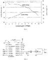
- the electronic ignition system has the following defects: the voltage is proportional to the rotation speed, and when the rotation speed is relatively low, the produced inductive current is small and the ignition voltage is relatively low wherein the relation of the ignition time point, the ignition voltage and the rotation speed is shown in FIG. 1 . Moreover, in the start-up stage, the rotation speed is relatively low, the ignition voltage cannot produce a large spark needed at this time and it is adverse to ignition, resulting in the difficulties to start the gasoline engine for the user to employ.
- the technical problem to be solved by the present invention is to provide a portable gasoline tool and an electronic ignition system thereof wherein the operation is simple and convenient, it can be started even if the rotation speed is relatively low in the start-up stage, enabling an enhanced user experience and facilitating popularization and promotion of the product.
- the first technical solution of the present invention is: an electronic ignition system for a portable gasoline tool, comprising a voltage boosting device and a spark plug connected with an output of the voltage boosting device; the electronic ignition system for the portable gasoline tool further comprises a DC power source and a controller electrically connected with the DC power source and connected with the voltage boosting device, wherein the controller controls ignition voltage and an ignition advance angle.
- the voltage boosting device boosts an output voltage of the DC power source to an ignition voltage; the output voltage of the DC power source is 6 V ⁇ 12 V, and the ignition voltage is 10 kV ⁇ 30 kV.
- the ignition voltage is 15 kV ⁇ 30 kV.
- the voltage boosting device comprises a plurality of stages of voltage boosting units; an output voltage of the lithium battery is boosted, through the plurality of stages of voltage boosting units, to the ignition voltage.
- the voltage boosting device comprises a first-stage voltage boosting unit and a second-stage voltage boosting unit, the first-stage voltage boosting unit boosts the voltage from the output voltage of the lithium battery to 200 V ⁇ 250 V, and the second-stage voltage boosting unit further boosts the voltage from 200 V ⁇ 250 V to the ignition voltage.
- the portable gasoline tool comprises: a body, and a flywheel provided on the body; the electronic ignition system further comprises: a sensing element provided on the flywheel or the body, and a position sensor provided on the body or the flywheel to obtain a rotation speed of the flywheel through the sensing element; the controller controls the ignition voltage and the ignition advance angle according to the rotation speed of the flywheel.
- the sensing element is provided on the flywheel and it is a magnet, with its number being at least one; the position sensor is provided on the body, with its number being one.
- the sensing element is provided on the flywheel and it is Fe, with its number being at least one; the position sensor is provided on the body, with its number being one, wherein the position sensor is an approach switch.
- the DC power source is a Li battery; the controller is an MCU controller.
- the DC power source is removable and rechargeable.
- the electronic ignition system further comprises a temperature sensor connected with the controller, the temperature sensor obtains an ambient temperature; the controller can control the ignition voltage and the ignition advance angle according to the ambient temperature.
- the voltage boosting device comprises an ignition coil.
- the second technical solution of the present invention is: a portable gasoline tool, comprising a body, a cylinder provided in the body, a piston movable to and fro in the cylinder, a crankshaft co-moved with the piston, a flywheel provided on the body and driven by the crankshaft to rotate, and the electronic ignition system described above.
- the controller with an MCU design can precisely control the ignition angle and energy.
- the controller can, with the change in rotation speed as detected by the position sensor, adjust the ignition angle at the appropriate time, thus making the gasoline engine work more stably.
- the operation is simple and convenient, and it can be started even if the rotation speed is relatively low in the start-up stage, thus enabling an enhanced user experience and facilitating popularization and promotion of the product.
- a first embodiment of an electronic ignition system for a portable gasoline tool comprising: a voltage boosting device and a spark plug 40 connected with an output of the voltage boosting device.
- the electronic ignition system for the portable gasoline tool further comprises a Direct Current (DC) power source 70 and a controller electrically connected with the DC power source 70 and connected with the voltage boosting device.
- the DC power source 70 is preferably a Li battery, more preferably a removable rechargeable lithium battery.
- the controller is a Micro Control Unit (MCU) controller, wherein the controller controls ignition voltage and an ignition advance angle.
- MCU Micro Control Unit
- a second embodiment of an electronic ignition system for a portable gasoline tool wherein the portable gasoline tool comprises: a body 10, and a flywheel 30 provided on the body 10 and drawn manually or electrically.
- the electronic ignition system for the portable gasoline tool comprises a voltage boosting device and a spark plug 40 connected with an output of the voltage boosting device.
- the electronic ignition system for the portable gasoline tool further comprises: a sensing element provided on the flywheel 30 or the body 10, and a position sensor 50 provided on the body 10 or the flywheel 30 to obtain a rotation speed of the flywheel 30 through the sensing element, and a controller electrically connected with the position sensor 50 and connected with the voltage boosting device, wherein the controller controls ignition voltage and an ignition advance angle.
- the sensing element is provided on the flywheel 30 and it is a magnet, with its number being at least two; and the position sensor 50 is provided on the body 10, with its number being one.
- the position sensor 50 is preferably a Hall element, or may be a photoelectric element or other elements.
- the sensing element comprises a positioning magnet 32 for initial positioning, and a measuring magnet 34 for rotation speed measurement, wherein the positioning magnet 32 is also referred as the top dead point positioning magnet.
- the present embodiment further comprises a Printed Circuit Board (PCB) 52 provided on the body 10 and electrically connected and fixed with the position sensor 50.
- the sensing element is provided in a circumferential direction of the flywheel 30, and the PCB 52 is located at a side of the flywheel 30 and is kept spaced from the flywheel 30.
- PCB Printed Circuit Board
- the sensing element is a magnet, with its number being one, and at least two position sensors are provided.
- the present embodiment further comprises a DC power source 70 providing electric energy to the controller.
- the DC power source 70 is preferably a Li battery, more preferably a removable lithium battery.
- the voltage boosting device boosts an output voltage of the Li battery to an ignition voltage, thus providing sufficient energy to ignite the fuel-gas mixture.
- the output voltage of the Li battery is 6 V ⁇ 12 V
- the ignition voltage is 10 kV ⁇ 30 kV.
- the voltage boosting device comprises a plurality of stages of voltage boosting units.
- the voltage boosting device comprises a first-stage voltage boosting unit and a second-stage voltage boosting unit, the first-stage voltage boosting unit boosts the voltage from the output voltage of the lithium battery to 200 V ⁇ 250 V, and the second-stage voltage boosting unit further boosts the voltage from 220 V ⁇ 250 V to the ignition voltage.
- the output voltage of the lithium battery is 6 V or 7.2 V.
- the voltage boosting device 241 first boosts the output voltage of the lithium battery to 220 V by a series induction manner, and then boosts the 220 V voltage to the ignition voltage wherein the ignition voltage is 15 kV ⁇ 30 kV.
- the voltage boosting device comprises an ignition coil.
- a third embodiment of a portable gasoline tool comprising: a body 10, a cylinder 20 provided in the body 10, a piston 60 movable to and fro within the cylinder 20, a crankshaft 62 driving the piston 60 to move, a flywheel 30 provided on the body 10 and driven by the crankshaft 62 to rotate, and an electronic ignition system which comprises a voltage boosting device and a spark plug 40 connected with an output of the voltage boosting device and provided on the cylinder 20.
- the electronic ignition system further comprises: a sensing element provided on the flywheel 30 or the body 10, a position sensor 50 provided on the body 10 or the flywheel 30 to obtain a rotation speed of the flywheel through the sensing element, and a controller electrically connected with the position sensor 50 and connected with the voltage boosting device.
- the sensing element is preferably provided on the flywheel 30 and it is a magnet, with its number being at least two; and the position sensor 50 is provided on the body 10, with its number being one.
- the position sensor 50 is preferably a Hall element, or may be a photoelectric element or other elements.
- the cylinder 20 is provided therein with a combustion chamber 22, wherein the spark plug 40 is fixed on the cylinder 20 and is at least partially extended into the combustion chamber 22.
- the sensing element comprises a positioning magnet 32 for initial positioning, and a measuring magnet 34 for rotation speed measurement, wherein the positioning magnet 32 is also referred as the top dead point positioning magnet.
- the present embodiment further comprises a PCB 52 provided on the body 10 and electrically connected and fixed with the position sensor 50.
- the sensing element is provided in a circumferential direction of the flywheel 30, and the PCB 52 is located at a side of the flywheel 30 and is kept spaced from the flywheel 30.
- the sensing element is a magnet, with its number being one, and at least two position sensors are provided.
- the position sensor 50 is preferably a Hall element, or may be a photoelectric element or other elements.
- the present embodiment further comprises a DC power source 70 providing electric energy to the controller, and a temperature sensor connected with the controller.
- a fourth embodiment of an electronic ignition system for a portable gasoline tool comprising: a voltage boosting device and a spark plug 40 connected with an output of the voltage boosting device.
- the electronic ignition system for the portable gasoline tool further comprises: a DC power source 70, and a controller electrically connected with the DC power source 70 and connected with the voltage boosting device, and a temperature sensor connected with the controller.
- the DC power source 70 is preferably a Li battery, more preferably a removable lithium battery.
- a fifth embodiment of an electronic ignition system for a portable gasoline tool wherein the portable gasoline tool comprises: a body 10, and a flywheel 30 provided on the body 10 and drawn manually or electrically.
- the electronic ignition system for the portable gasoline tool comprises a voltage boosting device and a spark plug 40 connected with an output of the voltage boosting device.
- the electronic ignition system for the portable gasoline tool further comprises: a sensing element provided on the flywheel 30 or the body 10, a position sensor 50 provided on the body 10 or the flywheel 30 to obtain a rotation speed of the flywheel through the sensing element, a controller electrically connected with the position sensor 50 and connected with the voltage boosting device, a DC power source 70 providing electric energy to the controller, and a temperature sensor connected with the controller.
- the position sensor 50 is preferably a Hall element, or may be a photoelectric element or other elements.
- the DC power source 70 is preferably a Li battery, more preferably a removable rechargeable lithium battery.
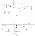
- an electric circuit function block diagram of the present invention comprises: a Li battery with its negative electrode connected to the ground, a power source module for voltage reduction connected with a positive electrode of the Li battery, a controller connected with the power source module, a damper controlling mechanism connected with the controller, a throttle controlling mechanism connected with the controller, an electrically-starting controlling mechanism connected with the controller, a high voltage ignition mechanism connected with the controller, a speed feedback mechanism connected with the controller and with a Hall element, and a temperature sensor connected with the controller, wherein the controller is provided therein with a main chip circuit and its electric circuit structure is specifically detailed in FIG. 6 , the inside electric circuit of the power source module is specifically detailed in FIG.
- the high voltage ignition mechanism comprises a voltage boosting device, a spark plug, and other element(s).
- the Li battery is used as the DC power source
- the position sensor is used to detect the rotation speed of the flywheel to determine the ignition angle
- the temperature sensor is used to detect the current temperature
- the controller converts the DC power source from a low voltage to a high voltage via the voltage boosting device.
- the controller according to various working conditions including the current rotation speed, working time, temperature, etc., calculates the currently necessary ignition angle and ignition voltage, then the electronic ignition system, with the angle calculated by the controller itself, uses a high voltage pack to release an electric spark with corresponding energy such that the fuel-gas mixture in the cylinder combusts, pushing the piston to move to and fro so that the gasoline engine is in an ideal working state.
- the temperature sensor is used to detect the current temperature and when the temperature is relatively low, the ignition voltage should be increased.
- the controller can control the ignition angle and energy such that the ignition occurs when the concentration in the cylinder is the highest, producing the largest spark, so that it is relatively easy to start the gasoline engine, easier to operate and higher in efficiency.
- magnet motor in the present invention, it is not necessary to install bulky magnet modules on the blades of the flywheel, and thus the weight of the blades can be reduced, so that the power (from the gasoline engine) consumed by the blades is relatively small and the whole efficiency of the system can be improved.
- the controller with an MCU design can precisely control the ignition angle and energy.
- the controller can, with the flywheel position detected by the position sensor and the flywheel rotation speed and with controlling of the program algorithms, adjust the ignition angle at the appropriate time.
- the controller can, with the flywheel position detected by the position sensor and the flywheel rotation speed and with controlling of the program algorithms, adjust the ignition angle at the appropriate time.
Landscapes
- Engineering & Computer Science (AREA)
- Chemical & Material Sciences (AREA)
- Combustion & Propulsion (AREA)
- Mechanical Engineering (AREA)
- General Engineering & Computer Science (AREA)
- Theoretical Computer Science (AREA)
- Signal Processing (AREA)
- Ignition Installations For Internal Combustion Engines (AREA)
- Portable Nailing Machines And Staplers (AREA)
Applications Claiming Priority (2)
| Application Number | Priority Date | Filing Date | Title |
|---|---|---|---|
| CN201610024698.XA CN105508117A (zh) | 2016-01-15 | 2016-01-15 | 便携式汽油工具及其电子点火系统 |
| PCT/CN2017/071178 WO2017121398A1 (fr) | 2016-01-15 | 2017-01-13 | Outil portatif à essence et son système d'allumage électronique |
Publications (3)
| Publication Number | Publication Date |
|---|---|
| EP3404251A1 true EP3404251A1 (fr) | 2018-11-21 |
| EP3404251A4 EP3404251A4 (fr) | 2019-02-13 |
| EP3404251B1 EP3404251B1 (fr) | 2026-03-11 |
Family
ID=55716347
Family Applications (1)
| Application Number | Title | Priority Date | Filing Date |
|---|---|---|---|
| EP17738211.6A Active EP3404251B1 (fr) | 2016-01-15 | 2017-01-13 | Outil portatif à essence et son système d'allumage électronique |
Country Status (4)
| Country | Link |
|---|---|
| US (1) | US10704521B2 (fr) |
| EP (1) | EP3404251B1 (fr) |
| CN (1) | CN105508117A (fr) |
| WO (1) | WO2017121398A1 (fr) |
Families Citing this family (4)
| Publication number | Priority date | Publication date | Assignee | Title |
|---|---|---|---|---|
| EP3663567A1 (fr) | 2016-01-15 | 2020-06-10 | Suzhou Cleva Precision Machinery & Technology Co., Ltd. | Outil de jardin |
| CN105508117A (zh) | 2016-01-15 | 2016-04-20 | 苏州科瓴精密机械科技有限公司 | 便携式汽油工具及其电子点火系统 |
| CN108757265B (zh) * | 2018-07-09 | 2024-01-05 | 苏州科瓴精密机械科技有限公司 | 一种发动机起动电路 |
| CN117437839A (zh) * | 2023-12-18 | 2024-01-23 | 西北师范大学 | 一种教学演示用内燃机及其使用方法 |
Family Cites Families (42)
| Publication number | Priority date | Publication date | Assignee | Title |
|---|---|---|---|---|
| EP0069889B1 (fr) * | 1981-07-03 | 1988-05-11 | Nissan Motor Co., Ltd. | Système d'allumage pour moteur à combustion interne |
| JPS62107272A (ja) * | 1985-10-31 | 1987-05-18 | Nippon Soken Inc | 内燃機関用点火装置 |
| CN1028890C (zh) * | 1992-06-16 | 1995-06-14 | 姜林 | 车辆上弹簧贮能式起动机 |
| IT1275771B1 (it) * | 1995-06-21 | 1997-10-17 | Ducati Energia Spa | Sistema elettronico di accensione con microcontrollore per motori a combustione interna invertibili |
| JP3410294B2 (ja) * | 1996-06-21 | 2003-05-26 | 三菱電機株式会社 | 内燃機関用ノック制御装置 |
| JP3799898B2 (ja) * | 1999-09-20 | 2006-07-19 | 株式会社日立製作所 | 筒内噴射式エンジンの制御装置 |
| JP3827059B2 (ja) | 2000-07-11 | 2006-09-27 | 本田技研工業株式会社 | エンジンの始動制御装置 |
| JP4270426B2 (ja) | 2001-01-31 | 2009-06-03 | スターテング工業株式会社 | エンジンの始動装置 |
| US6868832B2 (en) * | 2003-07-09 | 2005-03-22 | Honda Motor Co., Ltd. | Electronic controlled fuel injection apparatus of internal combustion engine |
| JP4199688B2 (ja) * | 2004-03-18 | 2008-12-17 | 本田技研工業株式会社 | オートチョーク装置 |
| JP2006061990A (ja) * | 2004-08-24 | 2006-03-09 | Hitachi Koki Co Ltd | 燃焼式動力工具 |
| JP4395841B2 (ja) * | 2004-09-29 | 2010-01-13 | 日立工機株式会社 | 燃焼式打込み工具 |
| US7525287B2 (en) | 2004-10-08 | 2009-04-28 | Husqvarna Zenoah Co., Ltd. | Battery pack for driving electric motor of compact engine starting device, engine starting device driven by the battery pack, and manual working machine having the engine starting device |
| DE102006038277B4 (de) | 2006-08-16 | 2021-01-21 | Andreas Stihl Ag & Co. Kg | Verfahren zum Regeln der Zusammensetzung eines Kraftstoff/Luft-Gemisches für einen Verbrennungsmotor |
| DE102006038278B4 (de) * | 2006-08-16 | 2022-02-17 | Andreas Stihl Ag & Co. Kg | Tragbares, handgeführtes Arbeitsgerät mit einer Datenverbindung zur Diagnose |
| JP4868523B2 (ja) | 2007-04-04 | 2012-02-01 | 京都電機器株式会社 | エンジンにおけるオートチョーク装置 |
| JP2009185695A (ja) | 2008-02-06 | 2009-08-20 | Walbro Japan Inc | 層状掃気用気化器 |
| US8219305B2 (en) * | 2008-05-27 | 2012-07-10 | Briggs & Stratton Corporation | Engine with an automatic choke and method of operating an automatic choke for an engine |
| JP4497238B2 (ja) * | 2008-09-16 | 2010-07-07 | トヨタ自動車株式会社 | 車両制御システム |
| CN101363380A (zh) * | 2008-10-09 | 2009-02-11 | 张和君 | 电控汽油发动机工作系统 |
| JP5256151B2 (ja) | 2009-09-02 | 2013-08-07 | 株式会社マキタ | 刈払機 |
| DE102009053236A1 (de) * | 2009-11-06 | 2011-05-12 | Andreas Stihl Ag & Co. Kg | Handgeführtes Arbeitsgerät mit einem luftgekühlten Verbrennungsmotor |
| EP2693019B1 (fr) * | 2011-03-31 | 2017-04-05 | Makita Corporation | Machine d'exploitation mobile dotée d'un système d'entraînement hybride |
| CN202047923U (zh) * | 2011-05-27 | 2011-11-23 | 山东绿环动力设备有限公司 | 一种四缸燃气发动机控制系统 |
| DE102012012798B4 (de) | 2012-06-28 | 2014-11-13 | Andreas Stihl Ag & Co. Kg | Arbeitsgerät mit einer Bremseinrichtung |
| DE102012024840A1 (de) * | 2012-12-19 | 2014-06-26 | Andreas Stihl Ag & Co. Kg | Verfahren zum Betrieb eines Verbrennungsmotors in einem handgeführten Arbeitsgerät |
| WO2014189064A1 (fr) | 2013-05-24 | 2014-11-27 | 株式会社デンソー | Dispositif de commande d'allumage pour moteur à combustion interne |
| CN103758671A (zh) * | 2014-01-14 | 2014-04-30 | 曲日 | 无噪声启动汽油发动机及其启动方法 |
| CN204253214U (zh) * | 2014-10-31 | 2015-04-08 | 白树春 | 适用于普通摩托车化油器使用的自动风门装置 |
| CN105484899B (zh) | 2016-01-15 | 2018-09-18 | 苏州科瓴精密机械科技有限公司 | 便携式汽油机及其自动风门控制系统 |
| CN105545562A (zh) | 2016-01-15 | 2016-05-04 | 苏州科瓴精密机械科技有限公司 | 小型汽油机 |
| CN205638762U (zh) | 2016-01-15 | 2016-10-12 | 苏州科瓴精密机械科技有限公司 | 便携式汽油工具及其电子点火系统 |
| CN205638728U (zh) | 2016-01-15 | 2016-10-12 | 苏州科瓴精密机械科技有限公司 | 便携式汽油机及其自动风门控制系统 |
| CN205503286U (zh) | 2016-01-15 | 2016-08-24 | 苏州科瓴精密机械科技有限公司 | 电动油门装置及其控制系统 |
| CN105508117A (zh) | 2016-01-15 | 2016-04-20 | 苏州科瓴精密机械科技有限公司 | 便携式汽油工具及其电子点火系统 |
| CN105464875B (zh) | 2016-01-15 | 2019-04-05 | 苏州科瓴精密机械科技有限公司 | 便携式汽油工具 |
| EP3663567A1 (fr) * | 2016-01-15 | 2020-06-10 | Suzhou Cleva Precision Machinery & Technology Co., Ltd. | Outil de jardin |
| CN105484876A (zh) | 2016-01-15 | 2016-04-13 | 苏州科瓴精密机械科技有限公司 | 电动油门装置及其控制系统 |
| CN205638760U (zh) | 2016-01-15 | 2016-10-12 | 苏州科瓴精密机械科技有限公司 | 小型汽油机 |
| CN205638761U (zh) | 2016-01-15 | 2016-10-12 | 苏州科瓴精密机械科技有限公司 | 便携式汽油工具 |
| CN105673290B (zh) | 2016-01-15 | 2018-11-09 | 苏州科瓴精密机械科技有限公司 | 便携式汽油工具 |
| CN205370829U (zh) | 2016-01-15 | 2016-07-06 | 苏州科瓴精密机械科技有限公司 | 便携式汽油工具 |
-
2016
- 2016-01-15 CN CN201610024698.XA patent/CN105508117A/zh active Pending
-
2017
- 2017-01-13 US US16/069,557 patent/US10704521B2/en active Active
- 2017-01-13 EP EP17738211.6A patent/EP3404251B1/fr active Active
- 2017-01-13 WO PCT/CN2017/071178 patent/WO2017121398A1/fr not_active Ceased
Also Published As
| Publication number | Publication date |
|---|---|
| CN105508117A (zh) | 2016-04-20 |
| US10704521B2 (en) | 2020-07-07 |
| EP3404251B1 (fr) | 2026-03-11 |
| EP3404251A4 (fr) | 2019-02-13 |
| WO2017121398A1 (fr) | 2017-07-20 |
| US20190024620A1 (en) | 2019-01-24 |
Similar Documents
| Publication | Publication Date | Title |
|---|---|---|
| US10704521B2 (en) | Portable gasoline tool and electronic ignition system thereof | |
| EP2088662A3 (fr) | Système générateur électrique portable | |
| CN105074198B (zh) | 内燃机的点火装置 | |
| EP2131428A4 (fr) | Dispositif de pile à combustible | |
| CN103890379B (zh) | 内燃机用控制装置 | |
| CN1052528C (zh) | 无电池车辆起动时用于减轻电负载的控制装置 | |
| US9222454B2 (en) | Capacitive igniter with a flameout time-delay function | |
| EP2816220A3 (fr) | Combustion et dispositif de commande de démarrage de secours à source de puissance auxiliaire et système associé | |
| CN104662286B (zh) | 发动机起动装置 | |
| CN205638762U (zh) | 便携式汽油工具及其电子点火系统 | |
| CA2518638A1 (fr) | Bloc d'alimentation destine a un vehicule | |
| CN103758671A (zh) | 无噪声启动汽油发动机及其启动方法 | |
| CN106150826B (zh) | 一种基于离子电流闭环控制的多次高能点火系统 | |
| CN203189129U (zh) | 一种发动机转速控制器 | |
| US20160297319A1 (en) | Portable propane-fueled battery charger | |
| CN202768218U (zh) | 用于发电机点火系统的自动切换保护系统 | |
| CN201837503U (zh) | 汽车发动机爆震传感器实验台架及电机控制电路 | |
| CN203347928U (zh) | 一种带点火功能的小型发动机电子控制单元 | |
| CN212154982U (zh) | 一种用于小型燃油机的电控化油器 | |
| CN106321325B (zh) | 一种可根据温度调整点火时刻的点火方法及装置 | |
| CN201687634U (zh) | 汽车多功能协调器 | |
| CN205876584U (zh) | 一种基于离子电流闭环控制的多次高能点火系统 | |
| CN202157890U (zh) | 摩托车点火装置 | |
| CN101893514A (zh) | 汽车发动机爆震传感器实验台架及电机控制电路 | |
| CN215672522U (zh) | 集成式点火器 |
Legal Events
| Date | Code | Title | Description |
|---|---|---|---|
| STAA | Information on the status of an ep patent application or granted ep patent |
Free format text: STATUS: THE INTERNATIONAL PUBLICATION HAS BEEN MADE |
|
| PUAI | Public reference made under article 153(3) epc to a published international application that has entered the european phase |
Free format text: ORIGINAL CODE: 0009012 |
|
| STAA | Information on the status of an ep patent application or granted ep patent |
Free format text: STATUS: REQUEST FOR EXAMINATION WAS MADE |
|
| 17P | Request for examination filed |
Effective date: 20180806 |
|
| AK | Designated contracting states |
Kind code of ref document: A1 Designated state(s): AL AT BE BG CH CY CZ DE DK EE ES FI FR GB GR HR HU IE IS IT LI LT LU LV MC MK MT NL NO PL PT RO RS SE SI SK SM TR |
|
| AX | Request for extension of the european patent |
Extension state: BA ME |
|
| A4 | Supplementary search report drawn up and despatched |
Effective date: 20190110 |
|
| RIC1 | Information provided on ipc code assigned before grant |
Ipc: F02P 5/15 20060101ALI20190104BHEP Ipc: F02N 11/08 20060101AFI20190104BHEP Ipc: F02P 5/00 20060101ALI20190104BHEP |
|
| DAV | Request for validation of the european patent (deleted) | ||
| DAX | Request for extension of the european patent (deleted) | ||
| STAA | Information on the status of an ep patent application or granted ep patent |
Free format text: STATUS: EXAMINATION IS IN PROGRESS |
|
| 17Q | First examination report despatched |
Effective date: 20220117 |
|
| GRAP | Despatch of communication of intention to grant a patent |
Free format text: ORIGINAL CODE: EPIDOSNIGR1 |
|
| STAA | Information on the status of an ep patent application or granted ep patent |
Free format text: STATUS: GRANT OF PATENT IS INTENDED |
|
| RIC1 | Information provided on ipc code assigned before grant |
Ipc: F02N 11/08 20060101AFI20250710BHEP Ipc: F02P 5/15 20060101ALI20250710BHEP Ipc: F02P 3/045 20060101ALI20250710BHEP Ipc: F02P 9/00 20060101ALI20250710BHEP Ipc: F02B 63/02 20060101ALN20250710BHEP |
|
| INTG | Intention to grant announced |
Effective date: 20250807 |
|
| GRAS | Grant fee paid |
Free format text: ORIGINAL CODE: EPIDOSNIGR3 |
|
| GRAA | (expected) grant |
Free format text: ORIGINAL CODE: 0009210 |
|
| STAA | Information on the status of an ep patent application or granted ep patent |
Free format text: STATUS: THE PATENT HAS BEEN GRANTED |
|
| AK | Designated contracting states |
Kind code of ref document: B1 Designated state(s): AL AT BE BG CH CY CZ DE DK EE ES FI FR GB GR HR HU IE IS IT LI LT LU LV MC MK MT NL NO PL PT RO RS SE SI SK SM TR |
|
| REG | Reference to a national code |
Ref country code: CH Ref legal event code: F10 Free format text: ST27 STATUS EVENT CODE: U-0-0-F10-F00 (AS PROVIDED BY THE NATIONAL OFFICE) Effective date: 20260311 Ref country code: GB Ref legal event code: FG4D |