EP3404260B1 - Taumelscheiben-kolbenpumpe mit variabler verdrängung - Google Patents
Taumelscheiben-kolbenpumpe mit variabler verdrängung Download PDFInfo
- Publication number
- EP3404260B1 EP3404260B1 EP16885103.8A EP16885103A EP3404260B1 EP 3404260 B1 EP3404260 B1 EP 3404260B1 EP 16885103 A EP16885103 A EP 16885103A EP 3404260 B1 EP3404260 B1 EP 3404260B1
- Authority
- EP
- European Patent Office
- Prior art keywords
- swash plate
- housing member
- rotary shaft
- piston
- housing
- Prior art date
- Legal status (The legal status is an assumption and is not a legal conclusion. Google has not performed a legal analysis and makes no representation as to the accuracy of the status listed.)
- Active
Links
Images


Classifications
-
- F—MECHANICAL ENGINEERING; LIGHTING; HEATING; WEAPONS; BLASTING
- F04—POSITIVE - DISPLACEMENT MACHINES FOR LIQUIDS; PUMPS FOR LIQUIDS OR ELASTIC FLUIDS
- F04B—POSITIVE-DISPLACEMENT MACHINES FOR LIQUIDS; PUMPS
- F04B1/00—Multi-cylinder machines or pumps characterised by number or arrangement of cylinders
- F04B1/12—Multi-cylinder machines or pumps characterised by number or arrangement of cylinders having cylinder axes coaxial with, or parallel or inclined to, main shaft axis
- F04B1/26—Control
- F04B1/30—Control of machines or pumps with rotary cylinder blocks
- F04B1/32—Control of machines or pumps with rotary cylinder blocks by varying the relative positions of a swash plate and a cylinder block
- F04B1/324—Control of machines or pumps with rotary cylinder blocks by varying the relative positions of a swash plate and a cylinder block by changing the inclination of the swash plate
-
- F—MECHANICAL ENGINEERING; LIGHTING; HEATING; WEAPONS; BLASTING
- F04—POSITIVE - DISPLACEMENT MACHINES FOR LIQUIDS; PUMPS FOR LIQUIDS OR ELASTIC FLUIDS
- F04B—POSITIVE-DISPLACEMENT MACHINES FOR LIQUIDS; PUMPS
- F04B1/00—Multi-cylinder machines or pumps characterised by number or arrangement of cylinders
- F04B1/12—Multi-cylinder machines or pumps characterised by number or arrangement of cylinders having cylinder axes coaxial with, or parallel or inclined to, main shaft axis
- F04B1/20—Multi-cylinder machines or pumps characterised by number or arrangement of cylinders having cylinder axes coaxial with, or parallel or inclined to, main shaft axis having rotary cylinder block
- F04B1/2014—Details or component parts
- F04B1/2064—Housings
-
- F—MECHANICAL ENGINEERING; LIGHTING; HEATING; WEAPONS; BLASTING
- F04—POSITIVE - DISPLACEMENT MACHINES FOR LIQUIDS; PUMPS FOR LIQUIDS OR ELASTIC FLUIDS
- F04B—POSITIVE-DISPLACEMENT MACHINES FOR LIQUIDS; PUMPS
- F04B1/00—Multi-cylinder machines or pumps characterised by number or arrangement of cylinders
- F04B1/12—Multi-cylinder machines or pumps characterised by number or arrangement of cylinders having cylinder axes coaxial with, or parallel or inclined to, main shaft axis
- F04B1/20—Multi-cylinder machines or pumps characterised by number or arrangement of cylinders having cylinder axes coaxial with, or parallel or inclined to, main shaft axis having rotary cylinder block
- F04B1/2014—Details or component parts
- F04B1/2078—Swash plates
-
- F—MECHANICAL ENGINEERING; LIGHTING; HEATING; WEAPONS; BLASTING
- F04—POSITIVE - DISPLACEMENT MACHINES FOR LIQUIDS; PUMPS FOR LIQUIDS OR ELASTIC FLUIDS
- F04B—POSITIVE-DISPLACEMENT MACHINES FOR LIQUIDS; PUMPS
- F04B53/00—Component parts, details or accessories not provided for in, or of interest apart from, groups F04B1/00 - F04B23/00 or F04B39/00 - F04B47/00
- F04B53/16—Casings; Cylinders; Cylinder liners or heads; Fluid connections
Definitions
- the swash plate includes a protrusion as a portion that contacts a control piston, which changes the inclination angle of the swash plate.
- the protrusion radially protrudes with respect to a section of the sliding contact surface.
- the housing of the variable displacement swash plate type piston pump has a first housing member and a second housing member both having a tubular shape with a bottom.
- the first housing member accommodates the cylinder block.
- the second housing member is coupled to the opening of the first housing member by means of a fastening tool such as bolts.
- the second housing member has a stopper.
- the opposite surface of the swash plate from the surface that contacts the control piston of the protrusion comes into contact with the stopper, thus limiting the inclination angle of the swash plate.
- Patent Document 2 discloses a variable displacement swash plate type piston pump.
- the protrusion comes into contact with the stopper of the second housing member after being moved by receiving force from the control piston. Therefore, the vicinity of the stopper in the second housing member is a section on which stress tends to concentrate relatively easily. That is, unless sufficient sealing performance is ensured in the sections of the first and second housing members corresponding to the protrusion of the swash plate, movement of the swash plate may deform the area of the housing around the section on which the stress concentrates. This may separate the first housing member from the second housing member. As a result, the hydraulic oil in the housing may leak from between the open end of the first housing member and the open end of the second housing member.
- variable displacement swash plate type piston pump capable of ensuring a sufficient sealing performance in a section of the housing on which stress concentrates.
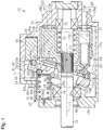
- a bottom wall 13a of the first housing member 13 has an insertion hole 13h.
- a section of the rotary shaft 12 corresponding to the first housing member 13 is inserted into the insertion hole 13h.
- the section of the rotary shaft 12 corresponding to the first housing member 13 is rotationally supported by the bottom wall 13a of the first housing member 13 with a bearing 15.
- a bottom wall 14a of the second housing member 14 has an insertion hole 14h.
- a section of the rotary shaft 12 corresponding to the second housing member 14 is inserted into the insertion hole 14h.
- the section of the rotary shaft 12 on the side corresponding to the second housing member 14 is rotationally supported by the bottom wall 14a of the second housing member 14 with a bearing 16.
- the cylinder block 17 rotates integrally with the rotary shaft 12. This causes the shoes 21 to contact and slide on the surface of the swash plate 18 opposed to the cylinder block 17.
- the pistons 20 are thus moved around the rotary shaft 12 in the circumferential direction of the rotary shaft 12. As a result, the pistons 20 reciprocate in the cylinder bores 17h by the stroke corresponding to the inclination angle of the swash plate 18 as the cylinder block 17 rotates.
- the bottom wall 13a of the first housing member 13 has a suction hole 26 and a discharge hole 27.
- the suction hole 26 and the discharge hole 27 both have a semi-arcuate shape extending in the circumferential direction of the rotary shaft 12.
- the suction hole 26 is arranged in the bottom wall 13a at a position at which the suction hole 26 is allowed to communicate with the cylinder bores 17h accommodating the pistons 20 in the suction strokes.
- the discharge hole 27 is arranged in the bottom wall 13a at a position at which the discharge hole 27 is allowed to communicate with the cylinder bores 17h accommodating the pistons 20 in the discharge strokes.
- the phrase "the pistons 20 in the suction stroke” herein refers to the pistons 20 that are moving from the top dead center to bottom dead center.
- the phrase “the pistons 20 in the discharge stroke” refers to the pistons 20 that are moving from the bottom dead center to top dead center.
- An annular valve plate 28 is arranged between the cylinder block 17 and the bottom wall 13a of the first housing member 13.
- the rotary shaft 12 is inserted inside the valve plate 28.
- the valve plate 28 is aligned with the cylinder block 17 in the axial direction of the rotary shaft 12.
- the valve plate 28 has an arcuate communication hole 28a around the rotary shaft 12 and has multiple arcuate communication holes 28b around the rotary shaft 12.
- the communication hole 28a allows communication between the suction hole 26 and the cylinder bores 17h.
- the communication holes 28b allow communication between the discharge hole 27 and the cylinder bores 17h. In the present embodiment, three communication holes 28b are provided.
- a closing portion 43 with a bottom is provided in a section of the outer circumferential wall of the second housing member 14.
- the closing portion 43 bulges outward in correspondence with the bulging portion 42 to close the opening of the recess 41.
- a section of the bottom surface of the closing portion 43 configures a stopper 43a.
- the protrusion 33 is capable of contacting the stopper 43a.
- the first bolt 51 and the second bolt 52 are arranged at the positions that are on the opposite sides of the recess 41, inside the width H1 of the swash plate 18 in the direction along the inclination axis L2 of the swash plate 18, and closer to the rotary shaft 12 than the distal ends 42e, 43e in the bulging direction of the bulging portion 42 and the closing portion 43.
- at least a part of each of the third and fourth bolts 53, 54 is arranged outside the width H1 of the swash plate 18.
- the center of the third bolt 53 and the center of the fourth bolt 54 are arranged outside the width H1 of the swash plate 18.
- a part of each of the third and fourth bolts 53, 54 is located inside the width H1 of the swash plate 18.
- each of the third and fourth bolts 53, 54 may be entirely arranged inside the width H1 of the swash plate 18.
- a press-fit pin for example, may be used as a fastening member.
Landscapes
- Engineering & Computer Science (AREA)
- Mechanical Engineering (AREA)
- General Engineering & Computer Science (AREA)
- Reciprocating Pumps (AREA)
Claims (3)
- Kolbenpumpe (10) vom Schrägscheiben-Typ mit variabler Verdrängung, aufweisend:ein Gehäuse (11);eine Drehwelle (12), die von dem Gehäuse (11) drehbar gelagert ist und eine Drehachse (L1) aufweist;einen Zylinderblock (17), der sich einstückig mit der Drehwelle (12) drehen kann; und
eine Taumelscheibe (18), die in dem Gehäuse (11) untergebracht ist und um einen Neigungswinkel um eine Neigungsachse (L2) in Bezug auf eine Richtung senkrecht zu der Drehachse (L1) der Drehwelle (12) neigbar ist, wobeidie Taumelscheibe (18) einen Vorsprung (33) aufweist, der sich nach außen erstreckt,
unddas Gehäuse (11) aufweistein rohrförmiges erstes Gehäuseteil (13), das den Zylinderblock (17) aufnimmt, undein rohrförmiges zweites Gehäuseteil (14), das mit einer Öffnungsseite desersten Gehäuseteils (13) gekoppelt ist,das erste Gehäuseteil (13) eine innere Umfangsfläche und eine äußere Umfangswand aufweist, wobei ein Abschnitt der inneren Umfangsfläche des ersten Gehäuseteils (13) eine Ausnehmung (41) aufweist, in der der Vorsprung (33) angeordnet ist,eine Kolbenaufnahmekammer (35), die mit der Ausnehmung (41) in Verbindung steht, in dem ersten Gehäuseteil (13) an einer Stelle außerhalb des Zylinderblocks (17) in einer radialen Richtung der Drehwelle (12) vorgesehen ist,ein Ausbauchungsabschnitt (42) in einem Abschnitt der äußeren Umfangswand des ersten Gehäuseteils (13) angeordnet ist, indem die Ausnehmung (41) und die Kolbenaufnahmekammer (35) vorgesehen sind, wobei der Ausbauchungsabschnitt (42) sich nach außen ausbaucht und sich in einer axialen Ausbauchungsrichtung senkrecht sowohl zur Drehachse (L1) der Drehwelle (12) als auch zur Neigungsachse (L2) der Taumelscheibe (18) des ersten Gehäuseteils (13) erstreckt,das zweite Gehäuseteil (14) eine äußere Umfangswand aufweist, wobei ein Abschnitt der äußeren Umfangswand des zweiten Gehäuseteils (14) einen Verschlussabschnitt (43) mit einem Boden aufweist, der sich in Übereinstimmung mit dem Ausbauchungsabschnitt (42) nach außen ausbaucht und eine Öffnung der Ausnehmung (41) verschließt,das erste Gehäuseteil (13) und das zweite Gehäuseteil (14) mittels einer Mehrzahl von Befestigungselementen (50) aneinander befestigt sind, unddie Befestigungselemente (50) ein erstes Befestigungselement (51) und ein zweites Befestigungselement (52) aufweisen, wobei die ersten und zweiten Befestigungselemente (51, 52) an Positionen angeordnet sind, die sichauf gegenüberliegenden Seiten der Ausnehmung (42), innerhalb einer Breite (H1) der Taumelscheibe (18) in einer Richtung entlang der Neigungsachse (L2) der Taumelscheibe (18), undnäher an der Drehwelle (12) als die distalen Enden (42e, 43e) des Ausbuchtungsabschnitts (42) und des Verschlussabschnitts (43), wobei die distalen Enden (42e, 43e) sich auf einer imaginären Linie (L3) befinden, die sich in der Ausbuchtungsrichtung erstreckt,wobeider Neigungswinkel in Bezug auf die Richtung senkrecht zur Rotationsachse (L1) der Drehwelle (12) veränderbar ist,die Kolbenaufnahmekammer (35) einen Steuerkolben (36) aufnimmt, der selektiv aus dem Kolbenaufnahmekammer (35) aus- und einfahrbar ist,der Kolbenaufnahmekammer (35) und der Steuerkolben (36) eine Steuerdruckkammer (35a) definieren, undein Abschnitt einer Bodenfläche des Verschlussabschnitts (43) einen Anschlag (43a) bildet, den der Vorsprung (33) berühren kann. - Kolbenpumpe (10) vom Schrägscheiben-Typ mit variabler Verdrängung nach Anspruch 1, ferner aufweisend einen Taumelscheibenhalteabschnitt (25), der die Taumelscheibe (18) hält, während er eine Änderung eines Neigungswinkels der Taumelscheibe (18) ermöglicht, wobei
die Taumelscheibe (18) einen Gleitabschnitt (32) aufweist, der eine Gleitfläche (32a) aufweist, die in einer bogenförmigen Form gekrümmt ist, die sich vom Zylinderblock (17) weg wölbt,
der Taumelscheibenhalteabschnitt (25) eine Gleitfläche aufweist, die sich entlang der Gleitfläche (32a) erstreckt und auf der die Gleitfläche (32a) gleitet, und
die Befestigungselemente (50), die sich von den ersten und zweiten Befestigungselementen (51, 52) unterscheiden und auf der gegenüberliegenden Seite des Gleitabschnitts (32) von den ersten und zweiten Befestigungselementen (51, 52) angeordnet sind, jeweils zumindest einen Teil aufweisen, der außerhalb der Breite (H1) der Taumelscheibe (18) angeordnet ist. - Kolbenpumpe (10) vom Schrägscheiben-Typ mit variabler Verdrängung nach Anspruch 1 oder 2, ferner aufweisend einen Taumelscheiben-Neigungswinkel-Wiederherstellungsmechanismus (37), der in dem zweiten Gehäuseteil (14) angeordnet und so konfiguriert ist, dass er die Taumelscheibe (18) berührt, um die Schrägscheibe (18) zu dem Steuerkolben (36) hin zu drängen, wobei, wenn sich die Taumelscheibe (18) in einem Neigungswinkel befindet, bei dem sich der Steuerkolben (36) in einer maximal in die Kolbenaufnahmekammer (35) zurückgezogenen Position befindet, ein Kontaktpunkt (P1) der Taumelscheibe (18) mit dem Taumelscheiben-Neigungswinkel-Wiederherstellungsmechanismus (37) in dem ersten Gehäuseteil (13) angeordnet ist.
Applications Claiming Priority (2)
| Application Number | Priority Date | Filing Date | Title |
|---|---|---|---|
| JP2016005426A JP6206513B2 (ja) | 2016-01-14 | 2016-01-14 | 可変容量型斜板式ピストンポンプ |
| PCT/JP2016/087775 WO2017122501A1 (ja) | 2016-01-14 | 2016-12-19 | 可変容量型斜板式ピストンポンプ |
Publications (3)
| Publication Number | Publication Date |
|---|---|
| EP3404260A4 EP3404260A4 (de) | 2018-11-21 |
| EP3404260A1 EP3404260A1 (de) | 2018-11-21 |
| EP3404260B1 true EP3404260B1 (de) | 2021-06-02 |
Family
ID=59311092
Family Applications (1)
| Application Number | Title | Priority Date | Filing Date |
|---|---|---|---|
| EP16885103.8A Active EP3404260B1 (de) | 2016-01-14 | 2016-12-19 | Taumelscheiben-kolbenpumpe mit variabler verdrängung |
Country Status (5)
| Country | Link |
|---|---|
| US (1) | US10487811B2 (de) |
| EP (1) | EP3404260B1 (de) |
| JP (1) | JP6206513B2 (de) |
| CA (1) | CA3010968C (de) |
| WO (1) | WO2017122501A1 (de) |
Families Citing this family (3)
| Publication number | Priority date | Publication date | Assignee | Title |
|---|---|---|---|---|
| JP7128753B2 (ja) * | 2019-01-24 | 2022-08-31 | Kyb株式会社 | 液圧回転機 |
| CN111173699B (zh) * | 2020-02-18 | 2025-11-11 | 华中科技大学无锡研究院 | 带压力保护水介质斜盘式轴向柱塞泵 |
| JP7590682B1 (ja) * | 2024-03-15 | 2024-11-27 | 株式会社不二越 | 可変容量制御ピストンポンプ |
Family Cites Families (18)
| Publication number | Priority date | Publication date | Assignee | Title |
|---|---|---|---|---|
| US2915985A (en) * | 1957-06-20 | 1959-12-08 | New York Air Brake Co | Pump |
| US3175510A (en) * | 1962-10-16 | 1965-03-30 | Amato Michael A D | Variable displacement pump |
| US3366072A (en) * | 1964-11-05 | 1968-01-30 | Sundstrand Corp | Pump or motor device |
| US3396536A (en) * | 1966-08-08 | 1968-08-13 | Cessna Aircraft Co | Hydraulic transmission |
| JPH0634625Y2 (ja) | 1990-07-12 | 1994-09-07 | 株式会社豊田自動織機製作所 | 可変容量型斜板式ピストンポンプ |
| JPH10159712A (ja) | 1996-12-03 | 1998-06-16 | Keihin Corp | 斜板式ポンプ |
| US7082762B1 (en) * | 1999-07-16 | 2006-08-01 | Hydro-Gear Limited Partnership | Pump |
| JP2005351140A (ja) * | 2004-06-09 | 2005-12-22 | Hitachi Constr Mach Co Ltd | 可変容量型斜板式液圧回転機 |
| JP4754313B2 (ja) | 2005-09-30 | 2011-08-24 | 川崎重工業株式会社 | 斜板式ピストンポンプ・モータ |
| JP5353464B2 (ja) | 2009-06-18 | 2013-11-27 | 株式会社豊田自動織機 | フォークリフト用油圧装置及び油圧ポンプ |
| DE102010048073A1 (de) * | 2010-04-16 | 2011-10-20 | Robert Bosch Gmbh | Maschinengehäuse einer Hydromaschine |
| DE102011113533A1 (de) * | 2011-09-15 | 2013-03-21 | Robert Bosch Gmbh | Hydrostatische Axialkolbenmaschine |
| JP2014126020A (ja) * | 2012-12-27 | 2014-07-07 | Kawasaki Heavy Ind Ltd | アキシャルピストンモータ |
| JP5679393B1 (ja) * | 2014-12-03 | 2015-03-04 | シャープ株式会社 | 送風装置 |
| JP5801504B2 (ja) * | 2015-02-16 | 2015-10-28 | ユーテック株式会社 | 扇風機 |
| JP6217727B2 (ja) * | 2015-10-15 | 2017-10-25 | 株式会社豊田自動織機 | 可変容量型ポンプ |
| JP6210101B2 (ja) * | 2015-10-22 | 2017-10-11 | 株式会社豊田自動織機 | 可変容量型ポンプ |
| CN205956040U (zh) * | 2016-07-07 | 2017-02-15 | 合一电器(深圳)有限公司 | 落地扇头部俯仰结构以及落地扇 |
-
2016
- 2016-01-14 JP JP2016005426A patent/JP6206513B2/ja active Active
- 2016-12-19 US US16/069,205 patent/US10487811B2/en active Active
- 2016-12-19 WO PCT/JP2016/087775 patent/WO2017122501A1/ja not_active Ceased
- 2016-12-19 EP EP16885103.8A patent/EP3404260B1/de active Active
- 2016-12-19 CA CA3010968A patent/CA3010968C/en active Active
Non-Patent Citations (1)
| Title |
|---|
| None * |
Also Published As
| Publication number | Publication date |
|---|---|
| CA3010968A1 (en) | 2017-07-20 |
| EP3404260A4 (de) | 2018-11-21 |
| US10487811B2 (en) | 2019-11-26 |
| US20190032645A1 (en) | 2019-01-31 |
| WO2017122501A1 (ja) | 2017-07-20 |
| JP6206513B2 (ja) | 2017-10-04 |
| CA3010968C (en) | 2019-08-20 |
| EP3404260A1 (de) | 2018-11-21 |
| JP2017125459A (ja) | 2017-07-20 |
Similar Documents
| Publication | Publication Date | Title |
|---|---|---|
| KR102298471B1 (ko) | 유압 펌프 | |
| CA3010968C (en) | Variable displacement swash plate type piston pump | |
| CN108071435B (zh) | 阀开闭时期控制装置 | |
| US11773848B2 (en) | Cartridge vane pump and pump device including same | |
| US11067067B2 (en) | Hydraulic device | |
| EP3037667B1 (de) | Vakuumpumpmechanismus | |
| EP3623626B1 (de) | Kartuschenartige flügelzellenpumpe und pumpenvorrichtung | |
| US10800124B2 (en) | Hydraulic drive | |
| JP6447362B2 (ja) | 可変容量型斜板式液圧回転機 | |
| US10174646B2 (en) | Valve opening and closing timing control apparatus | |
| EP3190274B1 (de) | Ventilöffnungs- und schliesszeitsteuerungsvorrichtung | |
| JP6106493B2 (ja) | シャトル弁及びそれを備えたポンプユニット | |
| JP4510998B2 (ja) | 油圧装置 | |
| EP3399186A1 (de) | Hydraulikvorrichtung | |
| JP7112280B2 (ja) | ポンプユニット | |
| EP3168471A1 (de) | Hydraulische drehmaschine | |
| US10132213B2 (en) | Valve opening and closing timing control apparatus | |
| JP6387327B2 (ja) | 可変容量型斜板式液圧回転機 | |
| US5775199A (en) | Rotary valve and directional valve combination | |
| JP2016061173A (ja) | 弁開閉時期制御装置 | |
| US11002136B2 (en) | Hydraulic system | |
| JP2018141389A (ja) | 液圧回転機 | |
| KR20240162085A (ko) | 회전 사판식 액압 펌프 | |
| JP2018141498A (ja) | シャトル弁及びこれを備えるポンプユニット | |
| JP2004068796A (ja) | ラジアルピストンポンプの制御機構 |
Legal Events
| Date | Code | Title | Description |
|---|---|---|---|
| STAA | Information on the status of an ep patent application or granted ep patent |
Free format text: STATUS: THE INTERNATIONAL PUBLICATION HAS BEEN MADE |
|
| PUAI | Public reference made under article 153(3) epc to a published international application that has entered the european phase |
Free format text: ORIGINAL CODE: 0009012 |
|
| STAA | Information on the status of an ep patent application or granted ep patent |
Free format text: STATUS: REQUEST FOR EXAMINATION WAS MADE |
|
| 17P | Request for examination filed |
Effective date: 20180731 |
|
| A4 | Supplementary search report drawn up and despatched |
Effective date: 20181008 |
|
| AK | Designated contracting states |
Kind code of ref document: A1 Designated state(s): AL AT BE BG CH CY CZ DE DK EE ES FI FR GB GR HR HU IE IS IT LI LT LU LV MC MK MT NL NO PL PT RO RS SE SI SK SM TR |
|
| AX | Request for extension of the european patent |
Extension state: BA ME |
|
| DAV | Request for validation of the european patent (deleted) | ||
| DAX | Request for extension of the european patent (deleted) | ||
| REG | Reference to a national code |
Ref country code: DE Ref legal event code: R079 Ref document number: 602016058974 Country of ref document: DE Free format text: PREVIOUS MAIN CLASS: F04B0001220000 Ipc: F04B0001206400 |
|
| GRAP | Despatch of communication of intention to grant a patent |
Free format text: ORIGINAL CODE: EPIDOSNIGR1 |
|
| STAA | Information on the status of an ep patent application or granted ep patent |
Free format text: STATUS: GRANT OF PATENT IS INTENDED |
|
| RIC1 | Information provided on ipc code assigned before grant |
Ipc: F04B 1/2078 20200101ALI20201123BHEP Ipc: F04B 1/2064 20200101AFI20201123BHEP Ipc: F04B 1/324 20200101ALI20201123BHEP Ipc: F04B 53/16 20060101ALI20201123BHEP |
|
| INTG | Intention to grant announced |
Effective date: 20201211 |
|
| GRAS | Grant fee paid |
Free format text: ORIGINAL CODE: EPIDOSNIGR3 |
|
| GRAA | (expected) grant |
Free format text: ORIGINAL CODE: 0009210 |
|
| STAA | Information on the status of an ep patent application or granted ep patent |
Free format text: STATUS: THE PATENT HAS BEEN GRANTED |
|
| RAP3 | Party data changed (applicant data changed or rights of an application transferred) |
Owner name: KABUSHIKI KAISHA TOYOTA JIDOSHOKKI |
|
| RIN1 | Information on inventor provided before grant (corrected) |
Inventor name: MATSUO, TSUTOMU Inventor name: YOKOMACHI, NAOYA Inventor name: UEDA, YUKI Inventor name: UNO, TAKASHI |
|
| REG | Reference to a national code |
Ref country code: CH Ref legal event code: EP |
|
| AK | Designated contracting states |
Kind code of ref document: B1 Designated state(s): AL AT BE BG CH CY CZ DE DK EE ES FI FR GB GR HR HU IE IS IT LI LT LU LV MC MK MT NL NO PL PT RO RS SE SI SK SM TR |
|
| REG | Reference to a national code |
Ref country code: GB Ref legal event code: FG4D |
|
| REG | Reference to a national code |
Ref country code: AT Ref legal event code: REF Ref document number: 1398684 Country of ref document: AT Kind code of ref document: T Effective date: 20210615 |
|
| REG | Reference to a national code |
Ref country code: IE Ref legal event code: FG4D |
|
| REG | Reference to a national code |
Ref country code: DE Ref legal event code: R096 Ref document number: 602016058974 Country of ref document: DE |
|
| REG | Reference to a national code |
Ref country code: LT Ref legal event code: MG9D |
|
| PG25 | Lapsed in a contracting state [announced via postgrant information from national office to epo] |
Ref country code: LT Free format text: LAPSE BECAUSE OF FAILURE TO SUBMIT A TRANSLATION OF THE DESCRIPTION OR TO PAY THE FEE WITHIN THE PRESCRIBED TIME-LIMIT Effective date: 20210602 Ref country code: FI Free format text: LAPSE BECAUSE OF FAILURE TO SUBMIT A TRANSLATION OF THE DESCRIPTION OR TO PAY THE FEE WITHIN THE PRESCRIBED TIME-LIMIT Effective date: 20210602 Ref country code: BG Free format text: LAPSE BECAUSE OF FAILURE TO SUBMIT A TRANSLATION OF THE DESCRIPTION OR TO PAY THE FEE WITHIN THE PRESCRIBED TIME-LIMIT Effective date: 20210902 Ref country code: HR Free format text: LAPSE BECAUSE OF FAILURE TO SUBMIT A TRANSLATION OF THE DESCRIPTION OR TO PAY THE FEE WITHIN THE PRESCRIBED TIME-LIMIT Effective date: 20210602 |
|
| REG | Reference to a national code |
Ref country code: NL Ref legal event code: MP Effective date: 20210602 |
|
| REG | Reference to a national code |
Ref country code: AT Ref legal event code: MK05 Ref document number: 1398684 Country of ref document: AT Kind code of ref document: T Effective date: 20210602 |
|
| PG25 | Lapsed in a contracting state [announced via postgrant information from national office to epo] |
Ref country code: GR Free format text: LAPSE BECAUSE OF FAILURE TO SUBMIT A TRANSLATION OF THE DESCRIPTION OR TO PAY THE FEE WITHIN THE PRESCRIBED TIME-LIMIT Effective date: 20210903 Ref country code: LV Free format text: LAPSE BECAUSE OF FAILURE TO SUBMIT A TRANSLATION OF THE DESCRIPTION OR TO PAY THE FEE WITHIN THE PRESCRIBED TIME-LIMIT Effective date: 20210602 Ref country code: RS Free format text: LAPSE BECAUSE OF FAILURE TO SUBMIT A TRANSLATION OF THE DESCRIPTION OR TO PAY THE FEE WITHIN THE PRESCRIBED TIME-LIMIT Effective date: 20210602 Ref country code: SE Free format text: LAPSE BECAUSE OF FAILURE TO SUBMIT A TRANSLATION OF THE DESCRIPTION OR TO PAY THE FEE WITHIN THE PRESCRIBED TIME-LIMIT Effective date: 20210602 Ref country code: PL Free format text: LAPSE BECAUSE OF FAILURE TO SUBMIT A TRANSLATION OF THE DESCRIPTION OR TO PAY THE FEE WITHIN THE PRESCRIBED TIME-LIMIT Effective date: 20210602 Ref country code: NO Free format text: LAPSE BECAUSE OF FAILURE TO SUBMIT A TRANSLATION OF THE DESCRIPTION OR TO PAY THE FEE WITHIN THE PRESCRIBED TIME-LIMIT Effective date: 20210902 |
|
| PG25 | Lapsed in a contracting state [announced via postgrant information from national office to epo] |
Ref country code: CZ Free format text: LAPSE BECAUSE OF FAILURE TO SUBMIT A TRANSLATION OF THE DESCRIPTION OR TO PAY THE FEE WITHIN THE PRESCRIBED TIME-LIMIT Effective date: 20210602 Ref country code: EE Free format text: LAPSE BECAUSE OF FAILURE TO SUBMIT A TRANSLATION OF THE DESCRIPTION OR TO PAY THE FEE WITHIN THE PRESCRIBED TIME-LIMIT Effective date: 20210602 Ref country code: AT Free format text: LAPSE BECAUSE OF FAILURE TO SUBMIT A TRANSLATION OF THE DESCRIPTION OR TO PAY THE FEE WITHIN THE PRESCRIBED TIME-LIMIT Effective date: 20210602 Ref country code: PT Free format text: LAPSE BECAUSE OF FAILURE TO SUBMIT A TRANSLATION OF THE DESCRIPTION OR TO PAY THE FEE WITHIN THE PRESCRIBED TIME-LIMIT Effective date: 20211004 Ref country code: NL Free format text: LAPSE BECAUSE OF FAILURE TO SUBMIT A TRANSLATION OF THE DESCRIPTION OR TO PAY THE FEE WITHIN THE PRESCRIBED TIME-LIMIT Effective date: 20210602 Ref country code: RO Free format text: LAPSE BECAUSE OF FAILURE TO SUBMIT A TRANSLATION OF THE DESCRIPTION OR TO PAY THE FEE WITHIN THE PRESCRIBED TIME-LIMIT Effective date: 20210602 Ref country code: ES Free format text: LAPSE BECAUSE OF FAILURE TO SUBMIT A TRANSLATION OF THE DESCRIPTION OR TO PAY THE FEE WITHIN THE PRESCRIBED TIME-LIMIT Effective date: 20210602 Ref country code: SM Free format text: LAPSE BECAUSE OF FAILURE TO SUBMIT A TRANSLATION OF THE DESCRIPTION OR TO PAY THE FEE WITHIN THE PRESCRIBED TIME-LIMIT Effective date: 20210602 Ref country code: SK Free format text: LAPSE BECAUSE OF FAILURE TO SUBMIT A TRANSLATION OF THE DESCRIPTION OR TO PAY THE FEE WITHIN THE PRESCRIBED TIME-LIMIT Effective date: 20210602 |
|
| REG | Reference to a national code |
Ref country code: DE Ref legal event code: R097 Ref document number: 602016058974 Country of ref document: DE |
|
| PLBE | No opposition filed within time limit |
Free format text: ORIGINAL CODE: 0009261 |
|
| STAA | Information on the status of an ep patent application or granted ep patent |
Free format text: STATUS: NO OPPOSITION FILED WITHIN TIME LIMIT |
|
| PG25 | Lapsed in a contracting state [announced via postgrant information from national office to epo] |
Ref country code: DK Free format text: LAPSE BECAUSE OF FAILURE TO SUBMIT A TRANSLATION OF THE DESCRIPTION OR TO PAY THE FEE WITHIN THE PRESCRIBED TIME-LIMIT Effective date: 20210602 |
|
| 26N | No opposition filed |
Effective date: 20220303 |
|
| PG25 | Lapsed in a contracting state [announced via postgrant information from national office to epo] |
Ref country code: AL Free format text: LAPSE BECAUSE OF FAILURE TO SUBMIT A TRANSLATION OF THE DESCRIPTION OR TO PAY THE FEE WITHIN THE PRESCRIBED TIME-LIMIT Effective date: 20210602 |
|
| PG25 | Lapsed in a contracting state [announced via postgrant information from national office to epo] |
Ref country code: MC Free format text: LAPSE BECAUSE OF FAILURE TO SUBMIT A TRANSLATION OF THE DESCRIPTION OR TO PAY THE FEE WITHIN THE PRESCRIBED TIME-LIMIT Effective date: 20210602 |
|
| REG | Reference to a national code |
Ref country code: CH Ref legal event code: PL |
|
| REG | Reference to a national code |
Ref country code: BE Ref legal event code: MM Effective date: 20211231 |
|
| PG25 | Lapsed in a contracting state [announced via postgrant information from national office to epo] |
Ref country code: LU Free format text: LAPSE BECAUSE OF NON-PAYMENT OF DUE FEES Effective date: 20211219 Ref country code: IE Free format text: LAPSE BECAUSE OF NON-PAYMENT OF DUE FEES Effective date: 20211219 |
|
| PG25 | Lapsed in a contracting state [announced via postgrant information from national office to epo] |
Ref country code: BE Free format text: LAPSE BECAUSE OF NON-PAYMENT OF DUE FEES Effective date: 20211231 |
|
| PG25 | Lapsed in a contracting state [announced via postgrant information from national office to epo] |
Ref country code: LI Free format text: LAPSE BECAUSE OF NON-PAYMENT OF DUE FEES Effective date: 20211231 Ref country code: CH Free format text: LAPSE BECAUSE OF NON-PAYMENT OF DUE FEES Effective date: 20211231 |
|
| P01 | Opt-out of the competence of the unified patent court (upc) registered |
Effective date: 20230519 |
|
| PG25 | Lapsed in a contracting state [announced via postgrant information from national office to epo] |
Ref country code: CY Free format text: LAPSE BECAUSE OF FAILURE TO SUBMIT A TRANSLATION OF THE DESCRIPTION OR TO PAY THE FEE WITHIN THE PRESCRIBED TIME-LIMIT Effective date: 20210602 |
|
| PG25 | Lapsed in a contracting state [announced via postgrant information from national office to epo] |
Ref country code: HU Free format text: LAPSE BECAUSE OF FAILURE TO SUBMIT A TRANSLATION OF THE DESCRIPTION OR TO PAY THE FEE WITHIN THE PRESCRIBED TIME-LIMIT; INVALID AB INITIO Effective date: 20161219 |
|
| PG25 | Lapsed in a contracting state [announced via postgrant information from national office to epo] |
Ref country code: MK Free format text: LAPSE BECAUSE OF FAILURE TO SUBMIT A TRANSLATION OF THE DESCRIPTION OR TO PAY THE FEE WITHIN THE PRESCRIBED TIME-LIMIT Effective date: 20210602 |
|
| PG25 | Lapsed in a contracting state [announced via postgrant information from national office to epo] |
Ref country code: TR Free format text: LAPSE BECAUSE OF FAILURE TO SUBMIT A TRANSLATION OF THE DESCRIPTION OR TO PAY THE FEE WITHIN THE PRESCRIBED TIME-LIMIT Effective date: 20210602 |
|
| PG25 | Lapsed in a contracting state [announced via postgrant information from national office to epo] |
Ref country code: MT Free format text: LAPSE BECAUSE OF FAILURE TO SUBMIT A TRANSLATION OF THE DESCRIPTION OR TO PAY THE FEE WITHIN THE PRESCRIBED TIME-LIMIT Effective date: 20210602 |
|
| PGFP | Annual fee paid to national office [announced via postgrant information from national office to epo] |
Ref country code: DE Payment date: 20251028 Year of fee payment: 10 |
|
| PGFP | Annual fee paid to national office [announced via postgrant information from national office to epo] |
Ref country code: GB Payment date: 20251030 Year of fee payment: 10 |
|
| PGFP | Annual fee paid to national office [announced via postgrant information from national office to epo] |
Ref country code: IT Payment date: 20251121 Year of fee payment: 10 |
|
| PGFP | Annual fee paid to national office [announced via postgrant information from national office to epo] |
Ref country code: FR Payment date: 20251110 Year of fee payment: 10 |