EP3404281A1 - Dispositif de fonctionnement d'un dispositif mécanique, en particulier d'un dispositif de freinage - Google Patents
Dispositif de fonctionnement d'un dispositif mécanique, en particulier d'un dispositif de freinage Download PDFInfo
- Publication number
- EP3404281A1 EP3404281A1 EP18167886.3A EP18167886A EP3404281A1 EP 3404281 A1 EP3404281 A1 EP 3404281A1 EP 18167886 A EP18167886 A EP 18167886A EP 3404281 A1 EP3404281 A1 EP 3404281A1
- Authority
- EP
- European Patent Office
- Prior art keywords
- pinion
- electric motor
- adjusting mechanism
- drive
- braking
- Prior art date
- Legal status (The legal status is an assumption and is not a legal conclusion. Google has not performed a legal analysis and makes no representation as to the accuracy of the status listed.)
- Granted
Links
Images


Classifications
-
- F—MECHANICAL ENGINEERING; LIGHTING; HEATING; WEAPONS; BLASTING
- F16—ENGINEERING ELEMENTS AND UNITS; GENERAL MEASURES FOR PRODUCING AND MAINTAINING EFFECTIVE FUNCTIONING OF MACHINES OR INSTALLATIONS; THERMAL INSULATION IN GENERAL
- F16D—COUPLINGS FOR TRANSMITTING ROTATION; CLUTCHES; BRAKES
- F16D59/00—Self-acting brakes, e.g. coming into operation at a predetermined speed
- F16D59/02—Self-acting brakes, e.g. coming into operation at a predetermined speed spring-loaded and adapted to be released by mechanical, fluid, or electromagnetic means
-
- F—MECHANICAL ENGINEERING; LIGHTING; HEATING; WEAPONS; BLASTING
- F16—ENGINEERING ELEMENTS AND UNITS; GENERAL MEASURES FOR PRODUCING AND MAINTAINING EFFECTIVE FUNCTIONING OF MACHINES OR INSTALLATIONS; THERMAL INSULATION IN GENERAL
- F16D—COUPLINGS FOR TRANSMITTING ROTATION; CLUTCHES; BRAKES
- F16D55/00—Brakes with substantially-radial braking surfaces pressed together in axial direction, e.g. disc brakes
- F16D55/02—Brakes with substantially-radial braking surfaces pressed together in axial direction, e.g. disc brakes with axially-movable discs or pads pressed against axially-located rotating members
- F16D55/22—Brakes with substantially-radial braking surfaces pressed together in axial direction, e.g. disc brakes with axially-movable discs or pads pressed against axially-located rotating members by clamping an axially-located rotating disc between movable braking members, e.g. movable brake discs or brake pads
- F16D55/224—Brakes with substantially-radial braking surfaces pressed together in axial direction, e.g. disc brakes with axially-movable discs or pads pressed against axially-located rotating members by clamping an axially-located rotating disc between movable braking members, e.g. movable brake discs or brake pads with a common actuating member for the braking members
- F16D55/2245—Brakes with substantially-radial braking surfaces pressed together in axial direction, e.g. disc brakes with axially-movable discs or pads pressed against axially-located rotating members by clamping an axially-located rotating disc between movable braking members, e.g. movable brake discs or brake pads with a common actuating member for the braking members in which the common actuating member acts on two levers carrying the braking members, e.g. tong-type brakes
-
- F—MECHANICAL ENGINEERING; LIGHTING; HEATING; WEAPONS; BLASTING
- F16—ENGINEERING ELEMENTS AND UNITS; GENERAL MEASURES FOR PRODUCING AND MAINTAINING EFFECTIVE FUNCTIONING OF MACHINES OR INSTALLATIONS; THERMAL INSULATION IN GENERAL
- F16D—COUPLINGS FOR TRANSMITTING ROTATION; CLUTCHES; BRAKES
- F16D2121/00—Type of actuator operation force
- F16D2121/02—Fluid pressure
- F16D2121/12—Fluid pressure for releasing a normally applied brake, the type of actuator being irrelevant or not provided for in groups F16D2121/04 - F16D2121/10
-
- F—MECHANICAL ENGINEERING; LIGHTING; HEATING; WEAPONS; BLASTING
- F16—ENGINEERING ELEMENTS AND UNITS; GENERAL MEASURES FOR PRODUCING AND MAINTAINING EFFECTIVE FUNCTIONING OF MACHINES OR INSTALLATIONS; THERMAL INSULATION IN GENERAL
- F16D—COUPLINGS FOR TRANSMITTING ROTATION; CLUTCHES; BRAKES
- F16D2121/00—Type of actuator operation force
- F16D2121/14—Mechanical
- F16D2121/16—Mechanical for releasing a normally applied brake
-
- F—MECHANICAL ENGINEERING; LIGHTING; HEATING; WEAPONS; BLASTING
- F16—ENGINEERING ELEMENTS AND UNITS; GENERAL MEASURES FOR PRODUCING AND MAINTAINING EFFECTIVE FUNCTIONING OF MACHINES OR INSTALLATIONS; THERMAL INSULATION IN GENERAL
- F16D—COUPLINGS FOR TRANSMITTING ROTATION; CLUTCHES; BRAKES
- F16D2125/00—Components of actuators
- F16D2125/18—Mechanical mechanisms
- F16D2125/20—Mechanical mechanisms converting rotation to linear movement or vice versa
- F16D2125/22—Mechanical mechanisms converting rotation to linear movement or vice versa acting transversely to the axis of rotation
- F16D2125/24—Rack-and-pinion
-
- F—MECHANICAL ENGINEERING; LIGHTING; HEATING; WEAPONS; BLASTING
- F16—ENGINEERING ELEMENTS AND UNITS; GENERAL MEASURES FOR PRODUCING AND MAINTAINING EFFECTIVE FUNCTIONING OF MACHINES OR INSTALLATIONS; THERMAL INSULATION IN GENERAL
- F16D—COUPLINGS FOR TRANSMITTING ROTATION; CLUTCHES; BRAKES
- F16D63/00—Brakes not otherwise provided for; Brakes combining more than one of the types of groups F16D49/00 - F16D61/00
- F16D63/006—Positive locking brakes
Definitions
- the invention relates to a device for actuating a mechanical device, in particular a braking device, with a from a starting or braking position in a functional or lifting position and vice versa movable adjusting mechanism, and an electric motor for moving the adjusting mechanism from the initial or braking position in the function - Or L Representative here, wherein the adjusting mechanism is provided with a rack and pinion gear, which meshes with a driven by the electric motor drive pinion, and wherein the electric motor transmits its torque via an executed as overrunning clutch on the drive pinion.
- Devices of the type in question may various mechanical devices, such as a door, a flap, a switch, a lever, a valve or in particular a brake actuate.
- essentially linear movements for adjusting, lifting, pressing or spreading can be carried out by a previously mentioned adjusting mechanism.
- the mechanical device to be operated has different positions, namely an initial or braking position and a functional or release position.
- the starting position may be defined for example by the closed position of the valve and the functional position by the open position of the valve. The situation is similar with the other facilities mentioned above.
- a device of the abovementioned type for actuating a brake device with a brake position and a release position is configured.
- a braking device is used, for example, the safe stopping and holding drive trains, in particular of rotating machine parts.
- she can For example, they can be used on chain conveyors or belt conveyors used to transport bulk materials such as coal, ore or rock in long-distance transport routes in mining and other industrial operations.
- brake devices ensure that the conveyor belt or the conveyor chains are brought to a standstill and held with the conveyed material lying thereon until operation is resumed.
- Electromechanical brakes per se are known from the prior art.
- a brake device of the above type is in the EP 2 669 543 A2 disclosed.
- an electric motor is also connected via an overrunning clutch with a drive pinion, wherein the drive pinion meshes with a rack of an actuating element of the braking device.
- About the connection of the drive pinion with the rack generated by the electric motor rotary motion of the motor shaft and the drive pinion is converted into a translational movement of the rack.
- such a design sometimes proves to be in need of improvement in brakes with high braking power, especially when the translational movement of the rack is to be transferred to two or more brake shoes.
- the force of a brake caliper coupled to such a transmission is eccentric, which is considered unsatisfactory in some applications.
- the present invention has for its object to provide a device of the type mentioned is available, which is significantly expanded and improved in terms of their potential applications and function with favorable production.
- the device according to the invention is characterized in that the rack and pinion drive has oppositely acting racks which are coupled to pistons and / or rods of the adjusting mechanism.
- the device according to the invention is advantageous, in particular, for actuating mechanical devices in which two or more translatory movements are to be carried out synchronously, but the mechanical device and / or the actuating device should nevertheless be made compact for this purpose.
- the inventive design allows an opposite, synchronous stroke of two pistons or rods. This can be used for example for operating tandem brakes or similar braking devices.
- a doubling of the braking torque can be achieved while avoiding an eccentric force.
- the embodiment of the actuating device according to the invention corresponds to a tandem design. It can also be referred to as an electromechanical actuator in tandem design or as a tandem actuator.
- the coupling designed as a one-way clutch By means of the coupling designed as a one-way clutch, it is prevented that the accelerated masses can not cause damage in the event of a hard stop when the mechanical device is rapidly or abruptly returned from a functional or release position to an initial or braking position.
- a rapid or abrupt movement of the actuating mechanism from a functional or release position to an initial or braking position is abruptly stopped in some cases, for example by a hard stop of the mechanical device, such as the impact of brake pads on a brake disc or brake drum.
- the one-way clutch prevents damaging loading or damage of all of the overrunning clutch upstream components, in particular of the electric motor. By the overrunning clutch thus braking torque peaks and a harmful load on the drive parts can be prevented.
- the adjusting mechanism is connected to a tensioning device, which is stretched when moving the adjusting mechanism from the initial or braking position to the functional or release position.
- tensioning the mechanical device when moving the adjusting mechanism in the functional or release position is possible that the adjusting mechanism moves in a power failure back to the starting or braking position. This behavior is called “fail-safe behavior.”
- the tensioning device is formed from elastic return elements, for example, from compression springs or air springs.
- elastic return elements for example, from compression springs or air springs.
- the compression springs are preferably designed in the form of a spring package.
- the clamping device may also have at least one air reservoir or an air spring as a spring element. Furthermore, it is advantageous if the clamping device is alternatively provided with a biasing device. As a result, the device according to the invention offers the possibility of being able to adjust the braking force as needed.
- the counter-acting racks are coupled with articulated linkage and / or levers such that an axial opposing movement of the racks by means of the articulated linkage and / or lever force increasing on the tensioning device for tensioning the return elements is transferable ,
- this configuration a smooth, power-reduced clamping of the restoring elements is possible in a relatively simple manner.
- a further preferred embodiment of the device according to the invention is characterized in that a driven by the electric motor drive shaft a holding device is provided, by means of which a movement of the adjusting mechanism from the functional or release position in the initial or braking position can be blocked.
- the holding device reliably ensures holding of the adjusting mechanism in a functional or release position. This embodiment is particularly advantageous in combination with the aforementioned clamping device.
- the holding device comprises a rotatably connected to the drive shaft pinion, a pinion associated spring-loaded latch and a detent pawl against the force of a spring element actuating electromagnet, the latch is moved in the de-energized state of the electromagnet by the spring element in a pinion unlocking position.
- This allows holding or keeping open the adjusting mechanism without the use of any hydraulics. The usually associated with a hydraulic sealing or aging problems can be completely avoided in this way.
- the electromagnet requires only a small power to fulfill the holding function. Due to this very low power consumption, the holding device heats only slightly in the above-mentioned preferred embodiment and thus requires no expensive cooling.
- the holding device can also be executed by a hydraulic auxiliary cylinder with electrically controllable valve or by the formation of the electric motor as a torque motor or standstill motor (also called rotary field magnet).
- a hydraulic auxiliary cylinder with electrically controllable valve or by the formation of the electric motor as a torque motor or standstill motor (also called rotary field magnet).
- the or one driven by the electric motor drive shaft is provided with a manually operable auxiliary drive, by means of which the adjusting mechanism is manually movable with currentless electric motor from the initial or braking position in the functional or release position.
- a manually operable auxiliary drive by means of which the adjusting mechanism is manually movable with currentless electric motor from the initial or braking position in the functional or release position.
- the device according to the invention without operation of the electric motor in a functional or release position be moved so that the mechanical device to be operated can be safely installed, set up, removed and replaced.
- brake pads or brake disc can be conveniently changed in this way.
- the manually operable auxiliary drive is not functional when the electric motor is running or decoupled from the drive shaft.
- the auxiliary drive has an axially slidably mounted threaded screw, which is provided with a return spring and at one end a form-fit and / or non-positively grippable portion having a threaded screw in engagement with a rotatably connected to the drive shaft motor pinion can be brought and automatically comes out of engagement with the motor pinion at a start of the electric motor.
- the threaded screw of the auxiliary drive can be brought in a reliable and smooth manner by means of a tool in engagement with a motor pinion and the adjusting mechanism can be moved manually from an initial or braking position to a functional or release position.
- the return spring ensures that when the electric motor is intentionally or unintentionally turned on, the threaded screw is automatically decoupled from the motor pinion without danger.
- the device according to the invention is part of one or the (previously mentioned) braking device.
- electromechanical brakes often require in practice a "fail-safe behavior", so that in case of power failure or failure of the electric motor of the brake, the associated transport or conveyor is reliably stopped until the power failure or motor error is resolved.
- the return elements of the clamping device in such an embodiment of the device according to the invention are not directly in the range of the rack and pinion drive, but in the region of the braking device or to arranged actuating mechanical device. More preferably, the braking device on a caliper or a brake caliper on which the tensioning device is arranged.
- the device according to the invention for actuating the braking device can thus exert high forces over long stroke paths with corresponding gear ratios.
- the path of the resilient return elements of the tensioning device is very low, so that the brake lining wear of the braking device has little or least effect on the change in the braking force of the braking device. As a result, a complex and expensive brake pad wear compensation can be omitted.
- a further preferred embodiment of the invention is characterized in that the electric motor via an angle gear, preferably an angle planetary gear, is connected to the meshing with the racks drive pinion.
- an angle gear preferably an angle planetary gear
- the overrunning clutch between the bevel gear and the drive pinion is arranged.
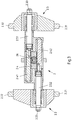
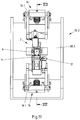
- FIGS. 1 to 5 is a first embodiment of a device for actuating a mechanical device, such as a braking device shown.
- the device comprises an actuating device 2 which can be moved from an initial or braking position into a functional or release position and vice versa, and an electric motor 4 for moving the adjusting mechanism 2 from the initial or braking position into the functional or release position.
- the electric motor 4 is connected via a gear 6, preferably an angular gear, and an overrunning clutch 8 with the adjusting mechanism 2.
- the transmission 6 is configured for example as an angle planetary gear.
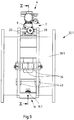
- the driven by the electric motor 4 motor or drive shaft 10 is associated with a holding device 12, by means of which a movement of the adjusting mechanism 2 from the functional or release position in the initial or braking position can be blocked.
- the operation and a preferred construction of the holding device 12 can be the Fig. 4 remove.
- an auxiliary drive 14 is arranged, by means of which the adjusting mechanism 2 is manually movable from the initial or braking position into the functional or release position when the electric motor 4 is de-energized (cf. Fig. 5a and 5b ).
- the actuation of the auxiliary drive 14 is preferably carried out by means of a tool 15, which is designed for example in the form of a hand crank. The operation of the auxiliary drive 14 will be described below with reference to the FIGS. 5a and 5b explained.
- the adjusting mechanism 2 is connected via the one-way clutch 8 and the transmission 6 to the drive shaft (motor shaft) 10 of the electric motor 4.
- a control box 18 for controlling the electric motor 4 is arranged on the adjusting mechanism 2.
- the holding device 12 can be controlled for example by means of an electrically controllable valve.
- the control box 18 is additionally connected to the holding device 12 and the electrically controllable valve of the holding device 12.
- the adjusting mechanism 2 has a base housing 2.1 and two housing parts 2.2 and 2.3 movably mounted thereon.
- the housing parts 2.2, 2.3 can also be referred to as adjusting body. They are movable relative to the base housing 2.1.
- the two housing parts 2.2, 2.3 are opposite to each other movable.
- Two opposing pivot pins 2.21 and 2.22 as well as 2.31 and 2.32 are respectively arranged on the housing parts 2.2, 2.3, to which linkage 20 (compare further exemplary embodiments in FIGS Fig. 9 and 10 such as Fig. 11 and 12 ) or levers can be hinged.
- the pivot pins 2.21, 2.22, 2.31 and 2.32 form the pivot axis for linkage 20 of brakes.
- the pivot pins 2.21, 2.22, 2.31 and 2.32 can be connected to drawbars 22 for actuating brake shoes 24 (see further exemplary embodiment in FIGS FIGS. 6 to 8 ).
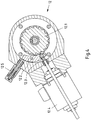
- Fig. 2 shows a plan view of the device Fig. 1 , In the Fig. 2 sectional views designated by the sectional lines III-III, IV-IV and Va-Va / Vb-Vb will be described below with reference to FIGS Figures 3 . 4 . 5a and 5b described.
- the rack and pinion drive 2.4 is composed of two oppositely acting racks 2.41 and 2.42, wherein the two racks 2.41, 2.42 mesh with a driven by the electric motor 4 drive pinion 26.
- the racks 2.41, 2.42 are mounted in the base housing 2.1 parallel to each other.
- To the racks 2.41, 2.42 close axially rod or bolt-shaped actuators 2.51, 2.52 of the actuating mechanism 2, wherein the two actuators 2.51, 2.52 via screw at one end thereof to the racks 2.41, 2.42 and at its other ends to the housing parts 2.2 , 2.3 are connected.
- the racks 2.41, 2.42 each have a threaded bore whose longitudinal axis runs parallel to the longitudinal axis of the toothed rack 2.41 or 2.42.
- a screw bolt is screwed, the thread or head with one of the actuators 2.51 and 2.52 is positively and / or non-positively connected.
- the housing parts 2.2, 2.3 are releasably attached to the racks 2.41, 2.42 remote from the ends of the actuators 2.51 and 2.52.
- the respective actuators 2.51, 2.52 is there each provided with a bolt-shaped end portion and a shoulder for receiving and axially fixing the housing part 2.2, 2.3, wherein the bolt-shaped end portion has an external thread for screwing a nut 2.23, 2.33.
- the actuators 2.51, 2.52 can also be referred to as guide rods.
- the electric motor 4 transmits its drive torque via the gear 6 and the overrunning clutch 8 to the drive pinion 26.
- the two housing parts 2.2, 2.3 are moved outwards or inwards.
- a mechanical device which is connected via the pivot pin 2.21, 2.22, 2.31 and 2.32 with the adjusting mechanism 2, moved from an initial or braking position to a functional or release position or vice versa.
- Holding device 12 shown has a rotatably connected to the drive shaft 10 motor pinion or pawl 12.1.
- the pawl 12.1 is assigned a spring-loaded latch 12.2.
- the latch 12.2 is pivotally mounted and is moved via a plunger 12.3 by an electromagnet 12.4, for example a solenoid, wherein the plunger 12.3 in combination with the latch 12.2 the Sperrklinkenrad 12.1 in the current leading, ie switched state of the electromagnet 12.4 blocks.
- the latch 12.2 is actuated against the force of a spring element 12.5.
- the spring element 12.5 is designed for example as a spring cartridge.
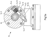
- Fig. 5a and 5b each show a sectional view of the auxiliary drive 14, on the one hand in engine operation ( Fig. 5a ) And on the other in manual mode with inserted tool 15 in the form of a hand crank.
- the auxiliary drive 14 may also be referred to as Handlmaj- or manual control device. It has an axially slidably mounted threaded screw (sliding screw) 14.1, which is provided with a return spring 14.2.
- the screw 14.1 can be moved against the force of the return spring 14.2 in a bore 14.5.
- the bore 14.5 has axial sections 14.51, 14.52, 14.53 with different inner diameter.
- the screw 14.1 axial sections with different outer diameter.
- the smallest inner diameter portion 14.51 of the bore is penetrated by a shaft-shaped portion 14.11 of the screw 14.1, wherein the shaft-shaped portion 14.11 axially slidably guided in the portion 14.51 of the bore.
- the shaft-shaped portion 14.11 is followed by a threaded portion 14.12, which engages by moving the screw 14.1 against the force of the return spring 14.2 with a motor pinion 14.3 in engagement.
- the return spring 14.2 designed as a helical spring surrounds the shaft-shaped section 14.11 and is supported on a shoulder 14.54 of the bore and on a shoulder 14.13 of the threaded screw 14.1.
- the guided through the section 14.51 of the bore section 14.11 of the screw 14.1 is provided at its end with an external thread and a mother mounted thereon 14.6.
- the nut 14.6 limited as a stop the induced by the return spring 14.2 restoring movement of the screw 14.1 into the bore 14.5.
- the threaded screw 14.1 has a diameter-expanded head 14.13 whose outer diameter is greater than the outer diameter of the threaded portion 14.12.
- the head 14.13 of the screw 14.1 is the largest inner diameter portion 14.53 of the bore 14.5 axially guided.
- the threaded screw 14.1 or the head 14.13 has a form-fit or frictionally engageable with the tool 15 section 14.4, which is designed for example as a hexagonal recess.
- the tool 15 When the electric motor 4 or power failure, the tool 15, if necessary, can be inserted into the section 14.4 and the restoring force of the return spring 14.2 be overcome manually using the tool 15, the threaded screw 14.1 passes by rotation of the tool 15 into engagement with the motor pinion 14.3 , Then, the adjusting mechanism 2 can be manually operated by the motor pinion 14.3 and thus the drive shaft (motor shaft) 10 are rotated by means of the tool (crank) 15, so that the mechanical device to be operated, for example a braking device from the starting or braking position in the Function or ventilation position is movable. Such a condition is in Fig. 5b shown.
- the auxiliary drive 14 due to the predetermined direction of rotation of the motor shaft 10 and the force of the return spring 14.2 automatically disengages from the motor pinion 14.3, so that the auxiliary drive 14 does not hinder the operation of the device according to the invention when the electric motor 4 is switched on.
- Fig. 6 shows a further embodiment of the device according to the invention with a braking device designed as a disc brake 28 in a plan view.
- the brake device (disc brake 28) is provided with a tensioning device 16.
- the disk brake 28 has brake shoes 24 arranged on multi-membered brake caliper arms 28.1, 28.2 with brake linings 30, which are pressed against a brake disk connected to a shaft, drive drum or the like so as to decelerate a transport or conveying device.
- brake shoes 24 arranged on multi-membered brake caliper arms 28.1, 28.2 with brake linings 30, which are pressed against a brake disk connected to a shaft, drive drum or the like so as to decelerate a transport or conveying device.
- the pivot pin 2.21, 2.22, 2.31 and 2.32 articulated power transmission members or drawbars 22 the movement of the adjusting mechanism 2 on the disc brake 28th transfer.
- the multi-piece brake caliper arms 28.1, 28.2 are pivotally connected to the drawbars 22.
- the two-armed members 28.11, 28.12 and 28.21, 28.22 of the brake caliper arms 28.1, 28.2 are pivotally mounted on a bearing part 28.3 of the disc brake 28, such that a Auffactzube admire the two actuating body or housing parts 2.2, 2.3 articulated by means of the adjusting mechanism 2 to a Sp Schwarzender to the drawbar 22 Sections of the two brake caliper arms 28.1, 28.2 leads, thereby hinged brake caliper members and finally the brake shoes 24 are brought into a braking position.
- the tensioning device 16 is coupled to the brake caliper arms 28.1 and 28.2, so that the tensioning device 16 is tensioned by moving the brake caliper arms 28.1, 28.2 into the release position.
- the brake shoes 24 are held by the electric motor 4 against the force of the tensioning device 16 in the release position.
- the tensioning device 16 is in the embodiment according to Fig. 6 made of elastic return elements 16.1 in the form of compression springs.
- the spring force of the tensioning device 16 causes the brake caliper arms 28.1, 28.2 and thus also with the brake caliper arms 28.1, 28.2 coupled actuating mechanism 2 back to the braking position and the Brake pads 30 are pressed against a brake disc or the like.
- Fig. 7 shows a sectional view of the device Fig. 6 along the section line VII-VII
- Fig. 8 a sectional view of the same device along the section line VIII-VIII shows.
- tension bars 22 are arranged on the pivot pin 2.21, 2.22, 2.31 and 2.32, which serve the power transmission from the adjusting mechanism 2 on the disc brake 28.
- the resilient return elements 16.1 of the clamping device 16 can be seen.
- FIGS. 9 and 10 show a further embodiment of the device according to the invention with a rod brake 32.1.
- the pivot pin 2.21, 2.22 and 2.31, 2.32 linkage 20 which are adapted to actuate brake calipers 34 via actuators 36.
- the moving parts of the linkage brake are attached to a connected to the base housing 2.1 of the adjusting mechanism 2 hood 38.1.
- the hood 38.1 preferably has a substantially closed circular shape, wherein the linkage 20 are connected via hinge elements 40 with the hood 38.1.
- the actuators 36 are connected to the hood 38.1, wherein the brake calipers 34 mounted in the actuators 36 pass through diametrically opposite passage openings 38.11, 38.12 of the hood 38.1.
- the linkage 20 are pivoted. The pivotal movement of the linkage 20 is transmitted via the actuating elements 36 to the brake calipers 34, whereby the linkage brake 32.1 can be moved to a braking or release position.
- the tensioning device 16 is formed in this embodiment of resilient restoring elements 16.1 in the form of spring assemblies or compression springs (brake springs), which are preferably arranged on the actuating mechanism 2 remote from the ends of the linkage 20 and hinged to the hood 38.1.
- the restoring elements 16.1 of the tensioning device 16 exert a spring force on the linkage 20 in a release position of the linkage brake 32.1, so that when the force exerted by the electric motor 4 on the linkage 20, the linkage 20 and the brake calipers 34 are moved into a braking position or snap back.
- Fig. 11 and 12 is a further embodiment of the device according to the invention with a rod brake 32.2 shown.
- the hood 38.2 is substantially U-shaped. You can do the execution according to the Figures 11 and 12 Also call open hood construction.
- the tensioning device 16 is arranged in this example between the actuators 36 and the adjusting mechanism 2 and connected to the hood 38.2 and the linkages 20, wherein the connection of the resilient return elements 16.1 is performed on the hood 38.2 in the form of a joint.
- the hood 38.2 is mounted on a base plate 42.
- the operation of such a rod brake 32.2 essentially corresponds to the operation of the in the Fig. 9 and 10 shown rod brake 32.1.
- rod brake 32.2 Due to the open hood construction, such a rod brake 32.2 can be simpler than the rod brake 32.1 with closed hood construction according to FIGS Fig. 9 and 10 mounted on a shaft or drive drum of a transport or conveying device and dismantled for maintenance and repair purposes.
- the embodiment of the invention is not limited to the embodiments shown in the drawing. On the contrary, numerous variants are conceivable which make use of the invention given in the attached claims, even if the design deviates from the examples shown.
- the restoring elements 16.1 of the tensioning device 16 can also be designed as air springs.
Landscapes
- Engineering & Computer Science (AREA)
- General Engineering & Computer Science (AREA)
- Mechanical Engineering (AREA)
- Physics & Mathematics (AREA)
- Electromagnetism (AREA)
- Braking Arrangements (AREA)
Priority Applications (1)
| Application Number | Priority Date | Filing Date | Title |
|---|---|---|---|
| PL18167886T PL3404281T3 (pl) | 2017-05-19 | 2018-04-18 | Zespół do uruchamiania układu mechanicznego, w szczególności układu hamulcowego |
Applications Claiming Priority (1)
| Application Number | Priority Date | Filing Date | Title |
|---|---|---|---|
| DE102017110985.4A DE102017110985A1 (de) | 2017-05-19 | 2017-05-19 | Vorrichtung zum Betätigen einer mechanischen Einrichtung, insbesondere einer Bremseinrichtung |
Publications (2)
| Publication Number | Publication Date |
|---|---|
| EP3404281A1 true EP3404281A1 (fr) | 2018-11-21 |
| EP3404281B1 EP3404281B1 (fr) | 2020-01-22 |
Family
ID=62025670
Family Applications (1)
| Application Number | Title | Priority Date | Filing Date |
|---|---|---|---|
| EP18167886.3A Active EP3404281B1 (fr) | 2017-05-19 | 2018-04-18 | Dispositif de fonctionnement d'un dispositif mécanique, en particulier d'un dispositif de freinage |
Country Status (3)
| Country | Link |
|---|---|
| EP (1) | EP3404281B1 (fr) |
| DE (1) | DE102017110985A1 (fr) |
| PL (1) | PL3404281T3 (fr) |
Citations (5)
| Publication number | Priority date | Publication date | Assignee | Title |
|---|---|---|---|---|
| FR2278987A1 (fr) * | 1975-03-26 | 1976-02-13 | Philadelphia Gear Corp | |
| DE102005059590A1 (de) * | 2005-12-14 | 2007-06-21 | Robert Bosch Gmbh | Trommelbremse |
| WO2009129764A1 (fr) * | 2008-04-24 | 2009-10-29 | Martin Stadlmeier | Frein à disque à réglage électrique |
| DE102010023700A1 (de) * | 2010-06-14 | 2011-12-15 | Pintsch Bubenzer Gmbh | Stellvorrichtung für eine selbstverstärkende Bremseinrichtung und selbstverstärkende Bremseinrichtung |
| EP2669543A2 (fr) | 2012-05-30 | 2013-12-04 | Tüschen & Zimmermann GmbH & Co. KG | Dispositif de ventilation et d'actionnement automatique d'un système de frein |
Family Cites Families (5)
| Publication number | Priority date | Publication date | Assignee | Title |
|---|---|---|---|---|
| US6119822A (en) * | 1998-11-30 | 2000-09-19 | Meritor Heavy Vehicle Systems, Llc | Drum brake with rack and pinion drive |
| DE10234848A1 (de) * | 2002-07-31 | 2004-02-19 | Robert Bosch Gmbh | Elektromechanische Bremse |
| KR100610119B1 (ko) * | 2004-12-16 | 2006-08-09 | 현대자동차주식회사 | 래크구동 디스크 브레이크 장치 |
| DE102010023701A1 (de) * | 2010-06-14 | 2011-12-15 | Pintsch Bubenzer Gmbh | Lüftgerät für eine Bremseinrichtung |
| DE102013009118A1 (de) * | 2012-06-13 | 2013-12-19 | Rainer Wolber | Weichenantrieb für ein Eisenbahngleis |
-
2017
- 2017-05-19 DE DE102017110985.4A patent/DE102017110985A1/de not_active Ceased
-
2018
- 2018-04-18 EP EP18167886.3A patent/EP3404281B1/fr active Active
- 2018-04-18 PL PL18167886T patent/PL3404281T3/pl unknown
Patent Citations (5)
| Publication number | Priority date | Publication date | Assignee | Title |
|---|---|---|---|---|
| FR2278987A1 (fr) * | 1975-03-26 | 1976-02-13 | Philadelphia Gear Corp | |
| DE102005059590A1 (de) * | 2005-12-14 | 2007-06-21 | Robert Bosch Gmbh | Trommelbremse |
| WO2009129764A1 (fr) * | 2008-04-24 | 2009-10-29 | Martin Stadlmeier | Frein à disque à réglage électrique |
| DE102010023700A1 (de) * | 2010-06-14 | 2011-12-15 | Pintsch Bubenzer Gmbh | Stellvorrichtung für eine selbstverstärkende Bremseinrichtung und selbstverstärkende Bremseinrichtung |
| EP2669543A2 (fr) | 2012-05-30 | 2013-12-04 | Tüschen & Zimmermann GmbH & Co. KG | Dispositif de ventilation et d'actionnement automatique d'un système de frein |
Also Published As
| Publication number | Publication date |
|---|---|
| DE102017110985A1 (de) | 2018-11-22 |
| EP3404281B1 (fr) | 2020-01-22 |
| PL3404281T3 (pl) | 2020-06-01 |
Similar Documents
| Publication | Publication Date | Title |
|---|---|---|
| EP0132601B1 (fr) | Tringlerie pour freins à friction de véhicules | |
| EP3107779B1 (fr) | Frein de véhicule automobile, en particulier frein de véhicule automobile actionnable hydrauliquement et électromécaniquement de manière combinée, avec broche à plusieurs étages | |
| DE2338706A1 (de) | Klemmvorrichtung fuer pressen u. dgl | |
| DE102011009540A1 (de) | Druckstangensteller für Kompakt-Bremszangeneinheiten mit gegen einen elastischen Anschlag anschlagbarem Stellhebel | |
| CH625470A5 (fr) | ||
| DE10230024C1 (de) | Schließmechanismus für eine Spritzgießmaschine | |
| DE10308017B4 (de) | Steuervorrichtung mit Klappanker | |
| DE4431321C2 (de) | Bremsgestänge für Fahrzeuge, insbesondere Schienenfahrzeuge | |
| DE102017124713B3 (de) | Greif- oder Spanneinheit, insbesondere zur Verwendung in einer Mensch-Roboter-Kollaboration und Verfahren | |
| EP2669543B1 (fr) | Dispositif de ventilation et d'actionnement automatique d'un système de frein | |
| DE2832801A1 (de) | Betaetigungseinrichtung fuer ein ventil | |
| EP0121815B1 (fr) | Dispositif automatique à action instantanée de rattrapage de jeu pour la course d'application de la timonerie de frein, notamment de véhicules ferroviaires | |
| DE602004007472T2 (de) | Motorisierter Aktuator für Fahrradgangschaltung, mit kontrolliertem Reibungsmechanismus | |
| EP3404281A1 (fr) | Dispositif de fonctionnement d'un dispositif mécanique, en particulier d'un dispositif de freinage | |
| EP3623267B9 (fr) | Dispositif de réglage d'un premier composant et d'un deuxième composant d'un moyen de transport des personnes et / ou des marchandises relatives les unes aux autres ainsi que moyen de transport des personnes et / ou des marchandises doté d'un tel dispositif | |
| DE102008018655A1 (de) | Trommelbremse | |
| WO2018130520A1 (fr) | Déverrouillage des freins de stationnement | |
| DE202004009839U1 (de) | Verstellantrieb | |
| DE2422850C3 (de) | Nachstellvorrichtung zum Ausgleich des Reibbelagverschleißes von Bremsen | |
| DE10054149A1 (de) | Federspeicherbremszylinder mit einer Notlöseeinrichtung | |
| EP2678477B1 (fr) | Véhicule poseur de pont équipé d'un dispositif de verrouillage | |
| DE102004049796B4 (de) | Linearantrieb | |
| DE4105286A1 (de) | Zangenartiges bremsgestaenge, insbesondere fuer scheibenbremsen von schienenfahrzeugen | |
| DE2735876A1 (de) | Bremsvorrichtung | |
| DE10249197B3 (de) | Verstellvorrichtung |
Legal Events
| Date | Code | Title | Description |
|---|---|---|---|
| PUAI | Public reference made under article 153(3) epc to a published international application that has entered the european phase |
Free format text: ORIGINAL CODE: 0009012 |
|
| STAA | Information on the status of an ep patent application or granted ep patent |
Free format text: STATUS: THE APPLICATION HAS BEEN PUBLISHED |
|
| AK | Designated contracting states |
Kind code of ref document: A1 Designated state(s): AL AT BE BG CH CY CZ DE DK EE ES FI FR GB GR HR HU IE IS IT LI LT LU LV MC MK MT NL NO PL PT RO RS SE SI SK SM TR |
|
| AX | Request for extension of the european patent |
Extension state: BA ME |
|
| STAA | Information on the status of an ep patent application or granted ep patent |
Free format text: STATUS: REQUEST FOR EXAMINATION WAS MADE |
|
| 17P | Request for examination filed |
Effective date: 20190516 |
|
| RBV | Designated contracting states (corrected) |
Designated state(s): AL AT BE BG CH CY CZ DE DK EE ES FI FR GB GR HR HU IE IS IT LI LT LU LV MC MK MT NL NO PL PT RO RS SE SI SK SM TR |
|
| GRAP | Despatch of communication of intention to grant a patent |
Free format text: ORIGINAL CODE: EPIDOSNIGR1 |
|
| STAA | Information on the status of an ep patent application or granted ep patent |
Free format text: STATUS: GRANT OF PATENT IS INTENDED |
|
| INTG | Intention to grant announced |
Effective date: 20190809 |
|
| GRAS | Grant fee paid |
Free format text: ORIGINAL CODE: EPIDOSNIGR3 |
|
| GRAA | (expected) grant |
Free format text: ORIGINAL CODE: 0009210 |
|
| STAA | Information on the status of an ep patent application or granted ep patent |
Free format text: STATUS: THE PATENT HAS BEEN GRANTED |
|
| AK | Designated contracting states |
Kind code of ref document: B1 Designated state(s): AL AT BE BG CH CY CZ DE DK EE ES FI FR GB GR HR HU IE IS IT LI LT LU LV MC MK MT NL NO PL PT RO RS SE SI SK SM TR |
|
| REG | Reference to a national code |
Ref country code: GB Ref legal event code: FG4D Free format text: NOT ENGLISH |
|
| REG | Reference to a national code |
Ref country code: CH Ref legal event code: EP |
|
| REG | Reference to a national code |
Ref country code: AT Ref legal event code: REF Ref document number: 1227099 Country of ref document: AT Kind code of ref document: T Effective date: 20200215 |
|
| REG | Reference to a national code |
Ref country code: IE Ref legal event code: FG4D Free format text: LANGUAGE OF EP DOCUMENT: GERMAN |
|
| REG | Reference to a national code |
Ref country code: DE Ref legal event code: R096 Ref document number: 502018000646 Country of ref document: DE |
|
| REG | Reference to a national code |
Ref country code: NL Ref legal event code: MP Effective date: 20200122 |
|
| REG | Reference to a national code |
Ref country code: LT Ref legal event code: MG4D |
|
| PG25 | Lapsed in a contracting state [announced via postgrant information from national office to epo] |
Ref country code: NO Free format text: LAPSE BECAUSE OF FAILURE TO SUBMIT A TRANSLATION OF THE DESCRIPTION OR TO PAY THE FEE WITHIN THE PRESCRIBED TIME-LIMIT Effective date: 20200422 Ref country code: FI Free format text: LAPSE BECAUSE OF FAILURE TO SUBMIT A TRANSLATION OF THE DESCRIPTION OR TO PAY THE FEE WITHIN THE PRESCRIBED TIME-LIMIT Effective date: 20200122 Ref country code: NL Free format text: LAPSE BECAUSE OF FAILURE TO SUBMIT A TRANSLATION OF THE DESCRIPTION OR TO PAY THE FEE WITHIN THE PRESCRIBED TIME-LIMIT Effective date: 20200122 Ref country code: RS Free format text: LAPSE BECAUSE OF FAILURE TO SUBMIT A TRANSLATION OF THE DESCRIPTION OR TO PAY THE FEE WITHIN THE PRESCRIBED TIME-LIMIT Effective date: 20200122 Ref country code: PT Free format text: LAPSE BECAUSE OF FAILURE TO SUBMIT A TRANSLATION OF THE DESCRIPTION OR TO PAY THE FEE WITHIN THE PRESCRIBED TIME-LIMIT Effective date: 20200614 |
|
| PG25 | Lapsed in a contracting state [announced via postgrant information from national office to epo] |
Ref country code: GR Free format text: LAPSE BECAUSE OF FAILURE TO SUBMIT A TRANSLATION OF THE DESCRIPTION OR TO PAY THE FEE WITHIN THE PRESCRIBED TIME-LIMIT Effective date: 20200423 Ref country code: BG Free format text: LAPSE BECAUSE OF FAILURE TO SUBMIT A TRANSLATION OF THE DESCRIPTION OR TO PAY THE FEE WITHIN THE PRESCRIBED TIME-LIMIT Effective date: 20200422 Ref country code: IS Free format text: LAPSE BECAUSE OF FAILURE TO SUBMIT A TRANSLATION OF THE DESCRIPTION OR TO PAY THE FEE WITHIN THE PRESCRIBED TIME-LIMIT Effective date: 20200522 Ref country code: SE Free format text: LAPSE BECAUSE OF FAILURE TO SUBMIT A TRANSLATION OF THE DESCRIPTION OR TO PAY THE FEE WITHIN THE PRESCRIBED TIME-LIMIT Effective date: 20200122 Ref country code: LV Free format text: LAPSE BECAUSE OF FAILURE TO SUBMIT A TRANSLATION OF THE DESCRIPTION OR TO PAY THE FEE WITHIN THE PRESCRIBED TIME-LIMIT Effective date: 20200122 Ref country code: HR Free format text: LAPSE BECAUSE OF FAILURE TO SUBMIT A TRANSLATION OF THE DESCRIPTION OR TO PAY THE FEE WITHIN THE PRESCRIBED TIME-LIMIT Effective date: 20200122 |
|
| REG | Reference to a national code |
Ref country code: DE Ref legal event code: R097 Ref document number: 502018000646 Country of ref document: DE |
|
| PG25 | Lapsed in a contracting state [announced via postgrant information from national office to epo] |
Ref country code: RO Free format text: LAPSE BECAUSE OF FAILURE TO SUBMIT A TRANSLATION OF THE DESCRIPTION OR TO PAY THE FEE WITHIN THE PRESCRIBED TIME-LIMIT Effective date: 20200122 Ref country code: ES Free format text: LAPSE BECAUSE OF FAILURE TO SUBMIT A TRANSLATION OF THE DESCRIPTION OR TO PAY THE FEE WITHIN THE PRESCRIBED TIME-LIMIT Effective date: 20200122 Ref country code: LT Free format text: LAPSE BECAUSE OF FAILURE TO SUBMIT A TRANSLATION OF THE DESCRIPTION OR TO PAY THE FEE WITHIN THE PRESCRIBED TIME-LIMIT Effective date: 20200122 Ref country code: SM Free format text: LAPSE BECAUSE OF FAILURE TO SUBMIT A TRANSLATION OF THE DESCRIPTION OR TO PAY THE FEE WITHIN THE PRESCRIBED TIME-LIMIT Effective date: 20200122 Ref country code: SK Free format text: LAPSE BECAUSE OF FAILURE TO SUBMIT A TRANSLATION OF THE DESCRIPTION OR TO PAY THE FEE WITHIN THE PRESCRIBED TIME-LIMIT Effective date: 20200122 Ref country code: EE Free format text: LAPSE BECAUSE OF FAILURE TO SUBMIT A TRANSLATION OF THE DESCRIPTION OR TO PAY THE FEE WITHIN THE PRESCRIBED TIME-LIMIT Effective date: 20200122 Ref country code: DK Free format text: LAPSE BECAUSE OF FAILURE TO SUBMIT A TRANSLATION OF THE DESCRIPTION OR TO PAY THE FEE WITHIN THE PRESCRIBED TIME-LIMIT Effective date: 20200122 |
|
| PLBE | No opposition filed within time limit |
Free format text: ORIGINAL CODE: 0009261 |
|
| STAA | Information on the status of an ep patent application or granted ep patent |
Free format text: STATUS: NO OPPOSITION FILED WITHIN TIME LIMIT |
|
| PG25 | Lapsed in a contracting state [announced via postgrant information from national office to epo] |
Ref country code: MC Free format text: LAPSE BECAUSE OF FAILURE TO SUBMIT A TRANSLATION OF THE DESCRIPTION OR TO PAY THE FEE WITHIN THE PRESCRIBED TIME-LIMIT Effective date: 20200122 |
|
| 26N | No opposition filed |
Effective date: 20201023 |
|
| PG25 | Lapsed in a contracting state [announced via postgrant information from national office to epo] |
Ref country code: LU Free format text: LAPSE BECAUSE OF NON-PAYMENT OF DUE FEES Effective date: 20200418 Ref country code: IT Free format text: LAPSE BECAUSE OF FAILURE TO SUBMIT A TRANSLATION OF THE DESCRIPTION OR TO PAY THE FEE WITHIN THE PRESCRIBED TIME-LIMIT Effective date: 20200122 Ref country code: FR Free format text: LAPSE BECAUSE OF NON-PAYMENT OF DUE FEES Effective date: 20200430 |
|
| REG | Reference to a national code |
Ref country code: BE Ref legal event code: MM Effective date: 20200430 |
|
| PG25 | Lapsed in a contracting state [announced via postgrant information from national office to epo] |
Ref country code: BE Free format text: LAPSE BECAUSE OF NON-PAYMENT OF DUE FEES Effective date: 20200430 Ref country code: SI Free format text: LAPSE BECAUSE OF FAILURE TO SUBMIT A TRANSLATION OF THE DESCRIPTION OR TO PAY THE FEE WITHIN THE PRESCRIBED TIME-LIMIT Effective date: 20200122 |
|
| PG25 | Lapsed in a contracting state [announced via postgrant information from national office to epo] |
Ref country code: IE Free format text: LAPSE BECAUSE OF NON-PAYMENT OF DUE FEES Effective date: 20200418 |
|
| PG25 | Lapsed in a contracting state [announced via postgrant information from national office to epo] |
Ref country code: LI Free format text: LAPSE BECAUSE OF NON-PAYMENT OF DUE FEES Effective date: 20210430 Ref country code: CH Free format text: LAPSE BECAUSE OF NON-PAYMENT OF DUE FEES Effective date: 20210430 |
|
| PG25 | Lapsed in a contracting state [announced via postgrant information from national office to epo] |
Ref country code: TR Free format text: LAPSE BECAUSE OF FAILURE TO SUBMIT A TRANSLATION OF THE DESCRIPTION OR TO PAY THE FEE WITHIN THE PRESCRIBED TIME-LIMIT Effective date: 20200122 Ref country code: MT Free format text: LAPSE BECAUSE OF FAILURE TO SUBMIT A TRANSLATION OF THE DESCRIPTION OR TO PAY THE FEE WITHIN THE PRESCRIBED TIME-LIMIT Effective date: 20200122 Ref country code: CY Free format text: LAPSE BECAUSE OF FAILURE TO SUBMIT A TRANSLATION OF THE DESCRIPTION OR TO PAY THE FEE WITHIN THE PRESCRIBED TIME-LIMIT Effective date: 20200122 |
|
| PG25 | Lapsed in a contracting state [announced via postgrant information from national office to epo] |
Ref country code: MK Free format text: LAPSE BECAUSE OF FAILURE TO SUBMIT A TRANSLATION OF THE DESCRIPTION OR TO PAY THE FEE WITHIN THE PRESCRIBED TIME-LIMIT Effective date: 20200122 Ref country code: AL Free format text: LAPSE BECAUSE OF FAILURE TO SUBMIT A TRANSLATION OF THE DESCRIPTION OR TO PAY THE FEE WITHIN THE PRESCRIBED TIME-LIMIT Effective date: 20200122 |
|
| GBPC | Gb: european patent ceased through non-payment of renewal fee |
Effective date: 20220418 |
|
| REG | Reference to a national code |
Ref country code: DE Ref legal event code: R081 Ref document number: 502018000646 Country of ref document: DE Owner name: RINGFEDER POWER TRANSMISSION GMBH, DE Free format text: FORMER OWNER: TUESCHEN & ZIMMERMANN GMBH & CO. KG, 57368 LENNESTADT, DE |
|
| PG25 | Lapsed in a contracting state [announced via postgrant information from national office to epo] |
Ref country code: GB Free format text: LAPSE BECAUSE OF NON-PAYMENT OF DUE FEES Effective date: 20220418 |
|
| P01 | Opt-out of the competence of the unified patent court (upc) registered |
Effective date: 20230517 |
|
| PGFP | Annual fee paid to national office [announced via postgrant information from national office to epo] |
Ref country code: CZ Payment date: 20240313 Year of fee payment: 7 |
|
| REG | Reference to a national code |
Ref country code: AT Ref legal event code: MM01 Ref document number: 1227099 Country of ref document: AT Kind code of ref document: T Effective date: 20230418 |
|
| PG25 | Lapsed in a contracting state [announced via postgrant information from national office to epo] |
Ref country code: AT Free format text: LAPSE BECAUSE OF NON-PAYMENT OF DUE FEES Effective date: 20230418 |
|
| PG25 | Lapsed in a contracting state [announced via postgrant information from national office to epo] |
Ref country code: AT Free format text: LAPSE BECAUSE OF NON-PAYMENT OF DUE FEES Effective date: 20230418 |
|
| PGFP | Annual fee paid to national office [announced via postgrant information from national office to epo] |
Ref country code: PL Payment date: 20240411 Year of fee payment: 7 |
|
| PGFP | Annual fee paid to national office [announced via postgrant information from national office to epo] |
Ref country code: DE Payment date: 20250424 Year of fee payment: 8 |
|
| PG25 | Lapsed in a contracting state [announced via postgrant information from national office to epo] |
Ref country code: CZ Free format text: LAPSE BECAUSE OF NON-PAYMENT OF DUE FEES Effective date: 20250418 |
|
| PGFP | Annual fee paid to national office [announced via postgrant information from national office to epo] |
Ref country code: AT Payment date: 20260410 Year of fee payment: 5 |