EP3404314A1 - Module d'éclairage d'un phare de véhicule automobile et phare de véhicule automobile doté d'un tel module d'éclairage - Google Patents
Module d'éclairage d'un phare de véhicule automobile et phare de véhicule automobile doté d'un tel module d'éclairage Download PDFInfo
- Publication number
- EP3404314A1 EP3404314A1 EP18172807.2A EP18172807A EP3404314A1 EP 3404314 A1 EP3404314 A1 EP 3404314A1 EP 18172807 A EP18172807 A EP 18172807A EP 3404314 A1 EP3404314 A1 EP 3404314A1
- Authority
- EP
- European Patent Office
- Prior art keywords
- light
- module
- sub
- light module
- circuit board
- Prior art date
- Legal status (The legal status is an assumption and is not a legal conclusion. Google has not performed a legal analysis and makes no representation as to the accuracy of the status listed.)
- Granted
Links
Images


Classifications
-
- F—MECHANICAL ENGINEERING; LIGHTING; HEATING; WEAPONS; BLASTING
- F21—LIGHTING
- F21S—NON-PORTABLE LIGHTING DEVICES; SYSTEMS THEREOF; VEHICLE LIGHTING DEVICES SPECIALLY ADAPTED FOR VEHICLE EXTERIORS
- F21S41/00—Illuminating devices specially adapted for vehicle exteriors, e.g. headlamps
- F21S41/10—Illuminating devices specially adapted for vehicle exteriors, e.g. headlamps characterised by the light source
- F21S41/14—Illuminating devices specially adapted for vehicle exteriors, e.g. headlamps characterised by the light source characterised by the type of light source
- F21S41/141—Light emitting diodes [LED]
- F21S41/147—Light emitting diodes [LED] the main emission direction of the LED being angled to the optical axis of the illuminating device
-
- B—PERFORMING OPERATIONS; TRANSPORTING
- B60—VEHICLES IN GENERAL
- B60Q—ARRANGEMENT OF SIGNALLING OR LIGHTING DEVICES, THE MOUNTING OR SUPPORTING THEREOF OR CIRCUITS THEREFOR, FOR VEHICLES IN GENERAL
- B60Q1/00—Arrangement of optical signalling or lighting devices, the mounting or supporting thereof or circuits therefor
- B60Q1/02—Arrangement of optical signalling or lighting devices, the mounting or supporting thereof or circuits therefor the devices being primarily intended to illuminate the way ahead or to illuminate other areas of way or environments
- B60Q1/04—Arrangement of optical signalling or lighting devices, the mounting or supporting thereof or circuits therefor the devices being primarily intended to illuminate the way ahead or to illuminate other areas of way or environments the devices being headlights
- B60Q1/06—Arrangement of optical signalling or lighting devices, the mounting or supporting thereof or circuits therefor the devices being primarily intended to illuminate the way ahead or to illuminate other areas of way or environments the devices being headlights adjustable, e.g. remotely-controlled from inside vehicle
- B60Q1/08—Arrangement of optical signalling or lighting devices, the mounting or supporting thereof or circuits therefor the devices being primarily intended to illuminate the way ahead or to illuminate other areas of way or environments the devices being headlights adjustable, e.g. remotely-controlled from inside vehicle automatically
- B60Q1/10—Arrangement of optical signalling or lighting devices, the mounting or supporting thereof or circuits therefor the devices being primarily intended to illuminate the way ahead or to illuminate other areas of way or environments the devices being headlights adjustable, e.g. remotely-controlled from inside vehicle automatically due to vehicle inclination, e.g. due to load distribution
-
- F—MECHANICAL ENGINEERING; LIGHTING; HEATING; WEAPONS; BLASTING
- F21—LIGHTING
- F21S—NON-PORTABLE LIGHTING DEVICES; SYSTEMS THEREOF; VEHICLE LIGHTING DEVICES SPECIALLY ADAPTED FOR VEHICLE EXTERIORS
- F21S41/00—Illuminating devices specially adapted for vehicle exteriors, e.g. headlamps
- F21S41/10—Illuminating devices specially adapted for vehicle exteriors, e.g. headlamps characterised by the light source
- F21S41/14—Illuminating devices specially adapted for vehicle exteriors, e.g. headlamps characterised by the light source characterised by the type of light source
- F21S41/141—Light emitting diodes [LED]
- F21S41/151—Light emitting diodes [LED] arranged in one or more lines
-
- F—MECHANICAL ENGINEERING; LIGHTING; HEATING; WEAPONS; BLASTING
- F21—LIGHTING
- F21S—NON-PORTABLE LIGHTING DEVICES; SYSTEMS THEREOF; VEHICLE LIGHTING DEVICES SPECIALLY ADAPTED FOR VEHICLE EXTERIORS
- F21S41/00—Illuminating devices specially adapted for vehicle exteriors, e.g. headlamps
- F21S41/10—Illuminating devices specially adapted for vehicle exteriors, e.g. headlamps characterised by the light source
- F21S41/19—Attachment of light sources or lamp holders
- F21S41/192—Details of lamp holders, terminals or connectors
-
- F—MECHANICAL ENGINEERING; LIGHTING; HEATING; WEAPONS; BLASTING
- F21—LIGHTING
- F21S—NON-PORTABLE LIGHTING DEVICES; SYSTEMS THEREOF; VEHICLE LIGHTING DEVICES SPECIALLY ADAPTED FOR VEHICLE EXTERIORS
- F21S41/00—Illuminating devices specially adapted for vehicle exteriors, e.g. headlamps
- F21S41/20—Illuminating devices specially adapted for vehicle exteriors, e.g. headlamps characterised by refractors, transparent cover plates, light guides or filters
- F21S41/25—Projection lenses
- F21S41/255—Lenses with a front view of circular or truncated circular outline
-
- F—MECHANICAL ENGINEERING; LIGHTING; HEATING; WEAPONS; BLASTING
- F21—LIGHTING
- F21S—NON-PORTABLE LIGHTING DEVICES; SYSTEMS THEREOF; VEHICLE LIGHTING DEVICES SPECIALLY ADAPTED FOR VEHICLE EXTERIORS
- F21S41/00—Illuminating devices specially adapted for vehicle exteriors, e.g. headlamps
- F21S41/30—Illuminating devices specially adapted for vehicle exteriors, e.g. headlamps characterised by reflectors
- F21S41/32—Optical layout thereof
- F21S41/321—Optical layout thereof the reflector being a surface of revolution or a planar surface, e.g. truncated
-
- F—MECHANICAL ENGINEERING; LIGHTING; HEATING; WEAPONS; BLASTING
- F21—LIGHTING
- F21S—NON-PORTABLE LIGHTING DEVICES; SYSTEMS THEREOF; VEHICLE LIGHTING DEVICES SPECIALLY ADAPTED FOR VEHICLE EXTERIORS
- F21S41/00—Illuminating devices specially adapted for vehicle exteriors, e.g. headlamps
- F21S41/30—Illuminating devices specially adapted for vehicle exteriors, e.g. headlamps characterised by reflectors
- F21S41/39—Attachment thereof
-
- F—MECHANICAL ENGINEERING; LIGHTING; HEATING; WEAPONS; BLASTING
- F21—LIGHTING
- F21S—NON-PORTABLE LIGHTING DEVICES; SYSTEMS THEREOF; VEHICLE LIGHTING DEVICES SPECIALLY ADAPTED FOR VEHICLE EXTERIORS
- F21S41/00—Illuminating devices specially adapted for vehicle exteriors, e.g. headlamps
- F21S41/40—Illuminating devices specially adapted for vehicle exteriors, e.g. headlamps characterised by screens, non-reflecting members, light-shielding members or fixed shades
- F21S41/43—Illuminating devices specially adapted for vehicle exteriors, e.g. headlamps characterised by screens, non-reflecting members, light-shielding members or fixed shades characterised by the shape thereof
-
- F—MECHANICAL ENGINEERING; LIGHTING; HEATING; WEAPONS; BLASTING
- F21—LIGHTING
- F21S—NON-PORTABLE LIGHTING DEVICES; SYSTEMS THEREOF; VEHICLE LIGHTING DEVICES SPECIALLY ADAPTED FOR VEHICLE EXTERIORS
- F21S41/00—Illuminating devices specially adapted for vehicle exteriors, e.g. headlamps
- F21S41/40—Illuminating devices specially adapted for vehicle exteriors, e.g. headlamps characterised by screens, non-reflecting members, light-shielding members or fixed shades
- F21S41/47—Attachment thereof
-
- F—MECHANICAL ENGINEERING; LIGHTING; HEATING; WEAPONS; BLASTING
- F21—LIGHTING
- F21S—NON-PORTABLE LIGHTING DEVICES; SYSTEMS THEREOF; VEHICLE LIGHTING DEVICES SPECIALLY ADAPTED FOR VEHICLE EXTERIORS
- F21S41/00—Illuminating devices specially adapted for vehicle exteriors, e.g. headlamps
- F21S41/60—Illuminating devices specially adapted for vehicle exteriors, e.g. headlamps characterised by a variable light distribution
- F21S41/65—Illuminating devices specially adapted for vehicle exteriors, e.g. headlamps characterised by a variable light distribution by acting on light sources
- F21S41/663—Illuminating devices specially adapted for vehicle exteriors, e.g. headlamps characterised by a variable light distribution by acting on light sources by switching light sources
-
- F—MECHANICAL ENGINEERING; LIGHTING; HEATING; WEAPONS; BLASTING
- F21—LIGHTING
- F21S—NON-PORTABLE LIGHTING DEVICES; SYSTEMS THEREOF; VEHICLE LIGHTING DEVICES SPECIALLY ADAPTED FOR VEHICLE EXTERIORS
- F21S45/00—Arrangements within vehicle lighting devices specially adapted for vehicle exteriors, for purposes other than emission or distribution of light
- F21S45/40—Cooling of lighting devices
- F21S45/47—Passive cooling, e.g. using fins, thermal conductive elements or openings
-
- F—MECHANICAL ENGINEERING; LIGHTING; HEATING; WEAPONS; BLASTING
- F21—LIGHTING
- F21S—NON-PORTABLE LIGHTING DEVICES; SYSTEMS THEREOF; VEHICLE LIGHTING DEVICES SPECIALLY ADAPTED FOR VEHICLE EXTERIORS
- F21S45/00—Arrangements within vehicle lighting devices specially adapted for vehicle exteriors, for purposes other than emission or distribution of light
- F21S45/40—Cooling of lighting devices
- F21S45/49—Attachment of the cooling means
Definitions
- the present invention relates to a light module of a headlamp of a motor vehicle.
- the light module comprises a first sub-module for producing a dimmed light distribution with a horizontal light-dark boundary, a second sub-module for illuminating a far region above the light-dark boundary and for realizing a high-beam distribution and a projection lens for imaging the light emitted by the two sub-modules as resulting light distribution of the light module on one Roadway in front of the motor vehicle.
- Both sub-modules each include at least one LED as a light source for emitting light, a heat sink in thermal contact with the LEDs for deriving the heat generated during operation of the LEDs, and primary optics for focusing the light emitted from the LEDs and for redirecting the light toward the projection lens.
- the primary optics of the submodules can act as a reflector, as a light guide or be designed as a front optics.
- the invention relates to a motor vehicle headlamp, which has a housing with a light exit opening formed in the light exit direction, which is closed by a transparent cover to prevent the ingress of moisture and / or dirt into the interior of the housing.
- a light module for emitting light and for generating a resulting light distribution on a roadway in front of the motor vehicle is arranged.
- Light modules and motor vehicle headlights of the type mentioned are known in various designs from the prior art.
- the light modules are each designed to realize one or more predetermined light functions and to realize certain light intensities and specially designed, wherein the light functions are realized with elements that are not interchangeable without further changes to the light module.
- elements for producing a conventional high beam distribution elements for generating a segmented high beam distribution (eg strip or partial high beam), elements for producing dimmed light distributions with different gradients of a light-dark border according to the legal requirements in Europe, the USA, Japan, China etc., and elements for producing a dimmed light distribution with different light intensities.
- Each of these light modules is designed and designed with all its components for the specific application. As a result, the development of new light modules for a new application is very complicated and expensive.
- the present invention therefore based on the object to design a lighting module of the type mentioned and further, that the waste heat of the LEDs during their operation can be derived as efficiently as possible to the environment of the light module and overheating of the LEDs is avoided.
- the light module has two separate, each one of the submodules associated heat sink, which are separated along a horizontal separation plane, wherein at least the at least one LED of the first sub-module on a circuit board fixed and electrically contacted and at least the circuit board for the at least one LED of the first sub-module is clamped with the light module mounted between the two heat sinks along the horizontal parting plane.
- the printed circuit board with the at least one LED of the first submodule is preferably designed as an Al-IMS (Insulated Metal Substrate) printed circuit board.
- the PCB absorbs most of the waste heat from the at least one LED and dissipates it.
- An advantage of the present invention is that the printed circuit board on both its underside and on its upper side a connection or contact surface to a heat sink, so that the heat transfer between the circuit board and the two-part heat sink of the light module is particularly efficient.
- the waste heat of the at least one LED is transmitted over a large area to the heat sink, which can then deliver them by convection to the environment.
- the invention has the advantage that the circuit board can be acted upon not only from above, but also from below with a cooling air flow, or that even the circuit board can deliver a part of the waste heat by convection on their top and bottom to the environment ,
- This allows a particularly efficient design and guidance of a cooling air flow in the light module around the circuit board around.
- this results in a particularly efficient cooling of the LEDs of the first sub-module, so that only the waste heat of the LEDs via convection can be derived so far that even with a long-term operation of the LEDs does not occur a functional impairment or even a defect of the LEDs due to overheating.
- By a suitable design and guidance of the air flow in the light module even the use of active cooling, for example by means of a fan, can be dispensed with, which leads to significant cost advantages and a significantly quieter operation of the light module.
- the at least one LED of the second sub-module is mounted on a circuit board and electrically contacted.
- the printed circuit board with the at least one LED of the second sub-module preferably comprises a FR4 composite with AlN inlays below the at least one LED.
- This type of circuit boards have a particularly good thermal conductivity, which is particularly important for the high-performance LEDs of the second sub-module, which generate relatively much waste heat.
- the printed circuit board for the at least one LED of the second sub-module is clamped between two heat sinks with the light module mounted.
- the two printed circuit boards of the two sub-modules could, for example, be clamped next to one another between the two heat sinks in the same horizontal plane.
- the heat sink of the light module consists of more than two partial heat sinks and the circuit board is clamped with the LEDs of the first sub-module between the first two heat sink parts and the circuit board with the LEDs of the second sub-module between other two heat sink parts.
- One of the heat sink parts, between which the circuit boards are clamped may be identical, so that a total of three superimposed heat sink parts would be sufficient to clamp the two circuit boards on different horizontal levels.
- the heat sinks of the two sub-modules each have a recess in which the remaining components of the respective sub-module are arranged.
- the individual components of the sub-modules can be used and fixed therein.
- a modular and highly flexible structure of the light module can be realized.
- a complete redesign of the entire light module as is the case in the prior art, if one of the elements is to produce a different light distribution, is thus not required in the light module according to the invention.
- a light module for generating a low beam by a first sub-module and a conventional high beam is designed by a second sub-module, it can be designed by exchanging some components of the second sub-module to produce a striped or partial high beam.
- the light source and the primary optics of the second submodule need to be replaced.
- the heat sink could be replaced, if necessary.
- the remaining light module, in particular the first submodule for generating the low beam, a holding frame, a lens holder and the projection lens can be taken over unchanged.
- the remaining light module in particular the heat sink of the first light module, the second submodule for generating the high beam, a holding frame, a lens holder and the projection lens can be adopted unchanged.
- the light module according to the invention can therefore be modularly composed of different components in the manner of a modular system, so that the sub-modules produce the desired light distributions with the desired light intensities.
- the printed circuit board is inserted with the at least one LED of the second sub-module in the recess, which is formed in the heat sink of the second sub-module.
- the printed circuit board can lie all over the surface on a bottom of the depression, so that even for this printed circuit board with the LEDs of the second submodule, a particularly large baffle or contact surface to the heat sink is realized for efficient heat dissipation.
- a circuit board with the at least one attached thereto and electrically contacted LED and then the primary optics of the second sub-module are used.
- the primary optics can be designed as a reflector or as a solid transparent plastic body, is coupled into the light, totally reflected and bundled and deflected coupled out again.
- the LED comprises at least one high power LED.
- the primary optic preferably formed as a reflector.
- a plurality of LEDs arranged side by side on the printed circuit board are provided, each of the LEDs emitting light for illuminating one of the strips of the strip or partial high-beam light.
- the primary optics of the second submodule be formed as a solid transparent plastic body, one of the at least one LED of the second submodule facing light entry surface, on the light emitted by the at least one LED, totally reflecting interfaces for redirecting the entered light and has a light emitting surface facing the projection lens when the light module is mounted, via which the deflected light emerges from the plastic body.
- the desired high beam distribution conventional high beam or strip or partial high beam.
- This can be realized either by using an additional wedge-shaped insert part, which is used on the heat sink under the board, or by using another heat sink with a correspondingly adapted recording for the board.
- the primary optics and then a circuit board with the at least one mounted thereon and electrically contacted LED are advantageously used.
- the components used are fastened in the recess.
- the at least one LED and the primary optics of the first sub-module are designed to emit a dimmed light distribution with a horizontal light-dark boundary.
- the reflection surface is subdivided into three strip-shaped segments, wherein the two lateral segments produce a broadly scattered basic light distribution with a symmetrical horizontal light-dark boundary and the middle segment generates a concentrated spotlight distribution with an asymmetrical light-dark boundary, wherein an overlay of the of the different segments of reflected light generates the low beam distribution.
- the light-dark boundary can be realized by a corresponding shape of the reflection surface.
- a diaphragm element to be arranged in the beam path of the light bundled and deflected by the primary optics, which shields a part of the bundled and deflected light.
- An edge of the diaphragm element can be imaged by the projection lens as a light-dark boundary on the road ahead of the motor vehicle.
- the diaphragm element is arranged in the light module such that at least the edge of the diaphragm element is arranged as part of the first sub-module on or above the horizontal separating plane.
- LEDs with different light intensities are mounted on different boards. Depending on which of the boards are used with LEDs in the recess of the heat sink of the first sub-module, sends the sub-module low beam with a specific light intensity. Under certain circumstances, it may then be necessary to exchange the primary optics in order to provide a reflection surface adapted to the respectively used LEDs.
- a plate-like mirrored diaphragm element extending in a horizontal plane when the light module is mounted with a front edge, which images the projection lens as a horizontal bright-dark boundary of the dimmed light distribution on the road ahead of the motor vehicle, as the last component in the recess of the heat sink of the second sub-module is used, wherein the front edge of the diaphragm element is arranged in mounted light module in or above the horizontal separation plane of the light module.
- the plate-like diaphragm element extending in a horizontal plane is preferably arranged completely in or above the horizontal separating plane when the light module is mounted.
- the diaphragm element is attached to the plastic body by means of hot stamping and then together with this in the recess of the heat sink of the second submodule used. In this way, can be dispensed with a separate attachment of the diaphragm element to one of the heat sink.
- the Heatsink of the two sub-modules each have a support surface, with which they abut each other with mounted light module and between which is clamped in the mounted light module, the circuit board with the at least one LED of the first sub-module.
- the bearing surfaces of the heat sink advantageously extend over a large part of a rear side directed counter to the light exit direction and on the sides of the heat sink of the two submodules.
- the depression formed therein is opened in the light exit direction to allow exit of the focused light from the primary optics arranged in the depression.
- the bearing surfaces of the heat sink thus have a U-shape, with the opening of the U in the light exit direction.
- the support surfaces heat exchange between the heat sinks and the clamped circuit board, so that always an optimal heat distribution and delivery is possible.
- the heat sinks are preferably fastened to one another when the light module is mounted, in particular by means of screws. At least some of the components of the sub-modules disposed in the recesses of the heatsinks are pressed into and held within the recesses by attaching the heatsinks to each other. In addition, an optimal heat exchange between the heat sinks can be made possible by the attachment.
- At least the heat sink of the second submodule have at least one ventilation opening on a front section directed in the light exit direction of the light module, can pass through the directed from bottom to top air flow to the clamped between the heat sinks circuit board with the at least one LED of the first sub-module.
- the front portion of the heat sink of the second sub-module has a planar extension in a substantially horizontal plane.
- a plurality of elongated openings may be formed, whose longitudinal axes are preferably parallel to each other and extend substantially in the light exit direction.
- ventilation openings By means of these ventilation openings, during the operation of the light module by convection, a downwardly directed upward air flow can form which, from below, strikes the printed circuit board with the at least one LED of the first submodule and ensures cooling of the printed circuit board.
- the ventilation openings also provide more efficient cooling of the other circuit board with the at least one LED of the second sub-module.
- the thermal properties of the light module can furthermore be improved by virtue of the fact that at least the heat sink of the first submodule has cooling ribs which have an areal extent in a vertical plane which runs parallel to a light exit direction of the light module, at least on an upper side directed upward with the light module mounted, wherein in each case a slot is formed in the cooling ribs and the slots of the cooling ribs are aligned with each other such that a ventilation gap results transversely to the surface extension of the cooling ribs through the slots of the cooling ribs.
- This ventilation gap ensures that the convection induced air flow in and around the cooling module not only parallel to the surface extension of the cooling fins, but also across it can run. This results in a more efficient cooling of the light module. It comes to turbulence in the region of the heat sink of the first sub-module, which promote a particularly good heat dissipation. There is a reduction of the thermal boundary layer between the heat sink and the air flow.
- At least the printed circuit board with the at least one LED of the first sub-module is formed as an Al-IMS (Aluminum Insulated Metal Substrate) printed circuit board. It is also proposed that at least the printed circuit board with the at least one LED of the second submodule comprises a FR4 composite with AlN inlays below the at least one LED. Such a printed circuit board is sold, for example, by the company Rayben®. Of course, it would also be conceivable that both circuit boards are formed with the LEDs of the first and the second sub-module as an Al-IMS circuit board or comprise a FR4 composite material with AlN inlays below the LEDs. These printed circuit boards allow a particularly good heat transfer between the at least one LED and the heatsinks. To improve heat dissipation, a thermal grease or thermal grease may be inserted between the LEDs and the circuit board.
- the heat sinks of the two sub-modules each have an opening directed against the light exit direction, via which plug elements are accessible from outside the light module, which are arranged on printed circuit boards with the at least one mounted and electrically contacted LED of the respective sub-modules and electrically contacted , about this plug elements, the LEDs of the light module can thus be electrically contacted and supplied with energy and / or drive signals.
- the two sub-modules are mounted with a directed in the light exit direction front of the heat sink to a support frame, via which the light module is mounted in a housing of the headlamp.
- a lens holder with the projection lens mounted thereon is mounted on a front side of the holding frame opposite the submodules.
- the lens holder is preferably designed as a largely closed tube, in particular made of a plastic material. The design of the lens holder as a tube, the leakage of unwanted scattered light can be prevented from the light module.
- the complete light module can be formed as a compact unit. It is particularly preferable if the holding frame and the lens holder for the projection lens consist of an Arnite® material which has particularly good heat-conducting properties and the thermal properties of the light module can additionally improve.
- the holding frame laterally has bearing points, via which the light module is mounted pivotably about a horizontal axis of rotation in the housing of the headlamp.
- a motor vehicle headlamp of the type mentioned wherein at least one inventive light module of the type described above is arranged inside the housing of the headlamp.
- at least one inventive light module of the type described above is arranged inside the housing of the headlamp.
- a plurality of light modules according to the invention in the headlight housing.
- each of the sub-modules of the light modules produce a different light distribution.
- a certain light distribution of the headlight is realized by a plurality of sub-modules and by superposition of the light distributions generated by these light modules.
- one of the sub-modules to produce a broadly scattered basic light distribution with a horizontal, strictly symmetrical light-dark boundary, while another of the sub-modules produces a concentrated spotlight distribution with an asymmetric light-dark boundary, a superposition of the base light and the spotlight forming a low-beam distribution in accordance with FIGS legal requirements.
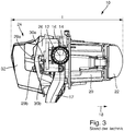
- FIG. 1 a known from the prior art light module is designated in its entirety by the reference numeral 10.
- the light module 10 is placed in a housing 102 (cf. FIG. 24 ) of a motor vehicle headlight 108 pivotally mounted about a horizontal axis 12.
- the pivot axis 12 is formed by bearings 14, which are arranged laterally on a support frame 16 of the light module 10 and mounted in corresponding bearing points in the headlight housing 102.
- the holding frame 16 is preferably made of plastic. Laterally on the holding frame 16, a lever 17 is arranged, on which an actuating element (not shown) is articulated, which causes the pivoting movement of the light module 10 about the horizontal axis 12.
- a lens holder 20 is fixed to the holding frame 16, which holds a projection lens 22 of the light module 10.
- a heat sink unit 24 of the light module 10 is attached, which in detail in FIG. 2 is shown.
- the heat sink unit 24 initially comprises the actual heat sink 26, which is made of a good heat conductive Material, in particular metal, preferably aluminum, is made. This is made in the art from one piece.
- the heat sink 26 is attached to the mounting frame 16 at a plurality of fastening points 28, for example by means of screws.
- a plurality of LEDs for emitting light and in the main emission direction in front of the LEDs are primary optics comprising a plurality of attachment optics 30 for bundling the light emitted by the LEDs and for deflecting the light in the direction of the projection lens 22 , In the example shown here, two rows of LEDs and front optics 30a, 30b are provided. In FIG.
- the LEDs are located behind (under) the attachment optics 30a, 30b and therefore not visible.
- the LEDs are indicated and designated by the reference numerals 29a, 29b.
- the heat sink 26 serves to deliver heat emitted by the LEDs during their operation to the environment. It includes cooling ribs 32 at its rear to increase the area for heat dissipation to the environment and to make the heat dissipation more efficient.
- the light module 10 comprises a first (upper) element for producing a dimmed light distribution with a horizontal light-dark boundary to which the in FIG. 2 is shown associated with the upper row of LEDs 29a and front optics 30a.
- a diaphragm element (not shown) which shadows at least part of the emitted light can be arranged in the beam path of the light emitted by the upper row of LEDs 29a and focused by the upper row of the auxiliary optics 30a.
- An edge of the diaphragm element is imaged by the projection lens 22 as a light-dark boundary on the roadway in front of the motor vehicle.
- the light module 10 Further includes the light module 10, a second (lower) element for illuminating a long range above the light-dark boundary and to realize a high beam distribution.
- the second element is associated with the lower row of LEDs 29b and auxiliary optics 30b.
- the light emitted by the two elements is imaged by the projection lens 22 as the resulting light distribution of the light module 10 on the road ahead of the motor vehicle.
- the entire light module 10 is formed with its elements as an integral unit. In particular, it only has a one-piece heat sink 26. If a different light distribution is to be generated in one of the elements, for example by the first element a dimmed light distribution with a greater light intensity, the entire light module 10 must be redesigned and developed, since this is more powerful or more LEDs 29a of the first element due to the larger Waste heat usually makes a transformation of the heat sink 26 required.
- the arrangement and contacting of the LEDs 29a is another, which requires the use of another board on which the LEDs 29a are mounted and electrically contacted.
- the known light module 10 is in particular not modular, so that it is not easy to replace individual components of the individual elements with other components in order to produce a different light distribution.
- the known light module 10 has a length 1. A shorter length 1 of the light module 10 is sought, so that the installation space of the light module 10 in the headlight housing 102 and thus the space required by the headlight 108 in the vehicle body space can be reduced.
- the thermal properties of the known light module 10 are not optimal. Due to the compact and highly integrated design of the light module 10 and the absence of an active cooling example. By means of a fan or blower, a more efficient cooling of the light module 10, in particular the LEDs 29a, 29b would be desirable to affect the functionality or even a defect of the LEDs 29a, 29b to avoid.
- a modular light module 10 is proposed.
- the light module 10 including the heat sink 26 is divided by a horizontal separation plane 34 in the two sub-modules, wherein all components of the first sub-module above the horizontal plane 34 and all components of the second sub-module below the horizontal plane 34 are arranged , Since the projection lens 22 can be assigned functionally neither the one nor the other sub-module, it is the only one not divided by the parting plane 34.
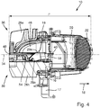
- FIGS. 4 to 6 Various embodiments of a light module 10 according to the invention are shown.
- FIG. 4 shows a first embodiment in a side view, partially in section.
- the light module 10 off FIG. 4 is in FIG. 5 shown in a perspective view.
- FIG. 4 shows a first embodiment in a side view, partially in section.
- the light module 10 off FIG. 4 is in FIG. 5 shown in a perspective view.
- FIG. 4 shows a first embodiment in a side view, partially in section.
- the light module 10 off FIG. 4 is in FIG. 5 shown
- FIG. 7 this embodiment is shown in an exploded view.
- FIG. 6 shows another embodiment, which in FIG. 8 shown in an exploded view.
- the sub-modules are designated by the reference numerals 36 and 38.
- the upper sub-module 36 has an upper heat sink 26a and the lower sub-module 38 is associated with a lower heat sink 26b.
- the upper sub-module 36 produces a conventional low-beam light distribution having a horizontal light-dark boundary or a portion thereof (eg, base or spot light).
- the light-dark boundary then depending on the design of the diaphragm element 40 (see. FIG. 7 ) or from the front edge 42 have an asymmetrical course. This is the case in the example shown here.
- the resulting light-dark border has a greater range on its own traffic side and serves, for example, for a conventional low-beam distribution or a spotlight of a low-beam distribution.
- the light-dark boundary may have a symmetrical (straight horizontal light-dark boundary) profile.
- a light-dark boundary is used, for example, for a broadly scattering basic light of a low-beam distribution.
- the diaphragm element 40 is preferably mirrored, so that the shaded light is at least partially reflected.
- the upper heat sink 26a of the upper submodule 36 of the light module 10 comprises a depression 44 into which the remaining components of the submodule 36 are inserted.
- These components include, for example, a primary optic in the form of a reflector 46 and a circuit board 48 with the arranged and electrically contacted LEDs 29 a.
- the LEDs 29a emit light in a built-up in the light module 10 board 48 light in a directed upward in the direction of the reflector 46 Hauptabstrahlraum 50 from.
- the reflector 46 focuses the light of the LEDs 29 a and deflects it in the light exit direction 18 in the direction of the projection lens 22.
- the upper sub-module 36 associated with aperture member 40 and its leading edge 42nd is arranged in the mounted state of the light module 10 either above, but at least on the horizontal parting plane 34.
- the lower sub-module 38 generates a high-beam distribution in the form of a matrix or stripe high beam.
- the illuminated area above the light-dark boundary is divided into a plurality of vertical strip-shaped segments, wherein each of the strips is illuminated by the light of at least one of the LEDs 29b.
- individual strips can be dimmed or turned off, for example, to prevent glare from other road users (eg, preceding or oncoming vehicle drivers) staying in the area illuminated by the dimmed or off LED 29b.
- the other road users are detected by suitable sensors (eg a front camera) and evaluation of the sensor signals in the motor vehicle and the individual LEDs 29b are activated accordingly.
- the lower heat sink 26b has a recess 52, in which the remaining components of the lower sub-module 38 are used.
- the LEDs 29b are arranged on a circuit board 54 and emit light in a main emission direction 56, which is directed approximately parallel to the main emission direction 50 of the upper LEDs 29a.
- the primary optics is formed in this case as an angled light guide 58 made of a solid plastic material, in which a via the LEDs 29b facing light entrance surface 58a (see. FIG. 12 ) is coupled at the bottom of the light emitted by the LEDs 29b in the direction 56 light.
- the light guide 58 has an oblique standing deflection surface 58 b, which is formed as a total reflecting interface of the light guide 58.
- the coupled-in light beams are deflected at the deflecting surface in the direction of a light exit surface 60 in the light exit direction 18 and in the direction of the projection lens 22.
- the diaphragm element 40 of the upper sub-module 36 can be fixed by means of hot stamping on the angled light guide 58 of the lower sub-module 38 and used together with this in the recess 52 of the lower heat sink 26 b. This eliminates a complex adjustment and fixing of the diaphragm element with respect to the upper LEDs 29 a.
- the diaphragm element 40 or its front edge 42 is arranged in a precisely defined position with respect to the upper LEDs 29a and secured in the light module 10. However, this does not change the fact that, in an assembled state of the light module 10, the diaphragm element 40, but at least its front edge 42, is arranged above the horizontal separating plane 34.
- a support surface 62 and on the upper side of the lower heat sink 26b a corresponding support surface 64 is formed.
- the bearing surfaces 62, 64 extend over a large part of a rear side directed against the light exit direction 18 and on the sides of the heat sinks 26a, 26b of the two submodules 36, 38.
- screws 66 for the reflector 46
- screws 68 for the circuit board 48 with the upper LEDs 29a
- screws 70 for the unit comprising the light guide 58 and the diaphragm member 40.
- the components can be mounted in other ways in the wells, for example.
- a locking or clip connection By means of a locking or clip connection.
- the heatsinks 26a, 26b are fastened together, for example by means of screws 72, so that the circuit board 48 is clamped along the horizontal parting plane 34 between the heat sinks 26a, 26b. In this way, a particularly good heat transfer between the clamped circuit board 48 and the heat sinks 26a, 26b results.
- the heat sinks 26a, 26b come into direct contact with one another, for example in the area of assembly aids, if such are provided. These are usually designed so that when properly installed the distance between the heat sinks 26a, 26b is determined only by the circuit board 48.
- the modular design of the light module 10 according to the invention in particular the compact and highly integrated structure of the heat sink unit 24 of the light module 10 according to the invention allows a very compact design of the light module 10 with a particularly short length, where l * of the light module 10 ⁇ l of the invention from the prior Technology is (cf. Figures 3 and 4 ).
- the heat sinks 26a, 26b of the two submodules 36, 38 each have an opening 78 on a rear side directed counter to the light exit direction 18 (cf. figure 17 ), are accessible via the connector elements 74 from outside the heat sinks 26a, 26b, which are arranged on printed circuit boards 48, 54 with at least one mounted and electrically contacted LED 29a, 29b of the respective sub-modules 36, 38 and electrically contacted.
- the upper LEDs 29a disposed on the circuit board 48 are contacted from above by the opening (not shown in the figures) formed in the heat sink 26a (see FIG. FIGS. 7 and 8th ).
- the lower LEDs 29b disposed on the circuit board 54 are contacted from behind by the opening 78 formed in the heat sink 26b.
- the openings 78 interrupt the peripheral bearing surfaces 62, 64 of the heat sinks 26a, 26b (see FIG. FIG. 17 ).
- the upper sub-module 36 for generating the low beam distribution is identical to the one formed in the first embodiment. Accordingly, the circuit boards 48 with the LEDs 29a of the first sub-module 36 in the Figures 13 and 15 also identically formed. All components including the heat sink 26a of the first sub-module 36 can thus be adopted unchanged.
- the lower sub-module 38 does not generate a matrix high beam but a normal high beam, with the far field above the bright-dark border being illuminated by the light emitted by the second sub-module 38.
- the sub-module 38 now comprises a circuit board 54 (cf. FIG.
- the primary optic in this case is formed as a reflector 76, which is the one of the LEDs 29b bundles emitted light and deflects in the light exit direction 18.
- the board 54 with the LEDs 29b mounted thereon is preferably inclined slightly backwards counter to the light exit direction 18, so that the main emission direction 56 of the LEDs 29b is directed obliquely backwards. Therefore, another heat sink 26b is used as in the first embodiment.
- the heat sink 29b used here has support points or a bearing surface on which the circuit board 54 is placed obliquely inclined backwards.
- the shutter member 40 is not fixed to the primary optic 76 of the lower sub-module 38 prior to insertion into one of the heatsinks 26a, 26b.
- the two heat sinks 26a, 26b with their bearing surfaces 62, 64 placed on each other and, for example. By screws 72. It is proposed that in this example, at least the circuit board 48 for the at least one LED 26a of the first Submodule 36 is clamped with mounted light module 10 between the two heat sinks 26a, 26b along the horizontal parting plane 34. In the example shown, the diaphragm element 40 is fastened by means of a latching connection in the recess 52 on the heat sink 26b.
- a desired light distribution can be generated by simply replacing individual components of one or more sub-modules 36, 38 with each of the light modules.
- the upper sub-module 36 it is also possible, by exchanging individual or several components of the upper sub-module 36, to modify it in such a way that it generates a different light distribution (for example a dimmed light distribution with a different light intensity) than in the exemplary embodiments.
- a different light distribution for example a dimmed light distribution with a different light intensity
- other LEDs 29a with a higher or lower power and / or in a different number would be used, so that the sub-module 36 generates a dimmed light distribution with a different light intensity.
- the use of other LEDs 29a requires the use of another board 48, for example of a different material or dimensions, a different plug element 74, etc.
- LEDs 29a may also require the use of a different board
- Another heat sink 26a requires, for example, with a higher heat dissipation, of a different material, with different dimensions, etc.
- the heat sinks 26a, 26b of the two sub-modules 36, 38 have - as stated - each have a support surface 62, 64, with which they abut each other with mounted light module 10 and between which with mounted light module 10, the circuit board 48 with at least one LED 29a of first sub-module 36 is clamped.
- the bearing surfaces 62, 64 preferably extend over a large part of a rear side directed counter to a light exit direction 18 of the light module 10 and on the sides of the heat sinks 26a, 26b of the two submodules 36, 38 (cf. FIGS. 7 and 8th ).
- the heat sinks 26a, 26b are fastened to each other when the light module 10 is mounted, in particular by means of screws 72.
- At least the cooling body 26b of the second sub-module 38 has at least one ventilation opening 82 on a front section 80 directed in the light exit direction 18 of the light module 10 (cf. Figures 17 and 23 ), through which a directed from bottom to top airflow 84 (see. FIG. 20 ) in a region of the light module 10 between the two recesses 44, 52 of the heat sink 26 a, 26 b of the two sub-modules 36, 38 can pass.
- the air flow 84 can reach the printed circuit board 48 clamped between the heat sinks 26a, 26b with the at least one LED 29a of the first submodule 26.
- the ventilation openings 82 ensure that there is no heat build-up in the interior of the light module 10 in the region of the depressions 44, 52.
- the printed circuit board 54 with the at least one LED 29b of the second sub-module 38 may have a recess 86 in the region of the ventilation openings 82 in order not to obstruct the air flow 84 when the light module 10 is mounted (cf. FIG. 16 ).
- At least the heat sink 26a of the first sub-module 36 has cooling ribs 90 at least on an upper side 88 which is directed upward when the light module 10 is mounted, which have a surface extension in a vertical plane that runs parallel to the light exit direction 18 of the light module 10.
- a slot 92 is formed in each case (see. Figures 20 and 21 ).
- the slots 92 of the cooling fins 90 are aligned with each other such that transversely to the surface extension of the cooling fins 90 through the slots 92 of the cooling fins 90 therethrough results in a ventilation gap 94 having a longitudinal extent parallel to the horizontal Rotary axis 12 of the light module 10 has (see. Figures 5 and 6 ).
- This ventilation gap 94 ensures that the convection-induced air flow 96 (see FIG. FIG. 22 ) in and around the light module 10 or its heat sink 26 a, 26 b around not only parallel to the surface extension of the cooling fins 90, but also can extend transversely thereto. This results in a more efficient cooling of the light module 10. There is turbulence in the region of the heat sink 26a of the first sub-module 36, which promote a particularly good heat dissipation. There is a reduction of the thermal boundary layer between the heat sink 26 a and the air flow 96.
- At least the printed circuit board 48 with the at least one LED 29a of the first sub-module 36 is formed as an Al-IMS (Insulated Metal Substrate) printed circuit board. It would also be conceivable that both circuit boards 48, 54 of the two sub-modules 36, 38 are formed as an Al-IMS circuit board.
- at least the printed circuit board 54 with the at least one LED 29b of the second submodule 38 comprises a FR4 composite with AlN inlays below the at least one LED 29b.
- the AlN inlay 98 is in contact with the heat sink 26a.
- Such a printed circuit board has particularly good heat-conducting properties.
- both printed circuit boards 48, 54 of the two sub-modules 36, 38 comprise a FR4 composite material with AlN inlays below the at least one LED 29a, 29b.
- a circuit board 54 made of a FR4 composite material with an AlN inlay 98 below the LEDs 29b is exemplified in FIG FIG. 18 shown.
- a TIM (Thermal Interface Material) 100 provides thermal coupling between the LEDs 29b and the heat sink 26b.
- the TIM 100 is, for example, a thermal adhesive or a thermal grease.
- the TIM 100 has a significant advantage in heat dissipation in the PCB 54 with ALN inlays 98.
- the viscous TIM 100 fills micropores (dimples with diameters and depths in the micrometer range) on the surface of the heat sink 26b, which is commonly manufactured as an aluminum die cast part is. Thereby, the heat transfer between the circuit board 54 and the heat sink 26 b can be further improved.
- the heat coupling or the heat transfer between the printed circuit board 54 and the heat sink 26b is in FIG. 18 indicated by double arrows W.
- the heat removal required for long-term reliable operation of the LEDs 29a, 29b is achieved solely by convection and thereby forming air streams and turbulences in the light module 10.
- Any measure to improve the thermal properties of the light module 10 may be essential to the invention per se. However, a particularly efficient cooling can be achieved by combining several of the proposed measures.
- an inventive motor vehicle headlight 108 which has a light-impermeable housing 102, which is preferably made of plastic.
- the housing 102 has in the light exit direction 18, a light exit opening 104 which is closed by a transparent cover 106 made of glass or plastic.
- an inventive light module 10 is arranged, which can produce a dimmed light distribution (eg, a low beam or a part thereof) and a high beam distribution.
- other light modules for generating other light distributions eg fog light
- the same light distributions as the light module 10 may also be arranged in the housing 102.
- lamp modules for generating one or more luminaire function eg flashing light, position light, daytime running light
Landscapes
- Engineering & Computer Science (AREA)
- General Engineering & Computer Science (AREA)
- Physics & Mathematics (AREA)
- Microelectronics & Electronic Packaging (AREA)
- Optics & Photonics (AREA)
- Mechanical Engineering (AREA)
- Non-Portable Lighting Devices Or Systems Thereof (AREA)
- Arrangement Of Elements, Cooling, Sealing, Or The Like Of Lighting Devices (AREA)
Applications Claiming Priority (1)
| Application Number | Priority Date | Filing Date | Title |
|---|---|---|---|
| DE102017110877.7A DE102017110877A1 (de) | 2017-05-18 | 2017-05-18 | Lichtmodul eines Kraftfahrzeugscheinwerfers und Kraftfahrzeugscheinwerfer mit einem solchen Lichtmodul |
Publications (2)
| Publication Number | Publication Date |
|---|---|
| EP3404314A1 true EP3404314A1 (fr) | 2018-11-21 |
| EP3404314B1 EP3404314B1 (fr) | 2022-02-23 |
Family
ID=62196429
Family Applications (1)
| Application Number | Title | Priority Date | Filing Date |
|---|---|---|---|
| EP18172807.2A Active EP3404314B1 (fr) | 2017-05-18 | 2018-05-17 | Module d'éclairage d'un phare de véhicule automobile et phare de véhicule automobile doté d'un tel module d'éclairage |
Country Status (2)
| Country | Link |
|---|---|
| EP (1) | EP3404314B1 (fr) |
| DE (1) | DE102017110877A1 (fr) |
Cited By (5)
| Publication number | Priority date | Publication date | Assignee | Title |
|---|---|---|---|---|
| EP3712490A1 (fr) * | 2019-03-22 | 2020-09-23 | ZKW Group GmbH | Dispositif de projection pour un phare de véhicule automobile |
| WO2021099290A1 (fr) * | 2019-11-19 | 2021-05-27 | Valeo Vision | Module d'eclairage pour vehicule a coupure modulable entre conduite a gauche et conduite a droite |
| RU225667U1 (ru) * | 2024-02-22 | 2024-05-02 | Федеральное государственное унитарное предприятие "Центральный ордена Трудового Красного Знамени научно-исследовательский автомобильный и автомоторный институт "НАМИ" | Светодиодный модуль для транспортного средства |
| WO2024121310A1 (fr) * | 2022-12-08 | 2024-06-13 | Valeo Vision | Dispositif d'éclairage pour projecteur de véhicule automobile. |
| WO2024129652A1 (fr) * | 2022-12-14 | 2024-06-20 | Lumileds Llc | Module d'éclairage pourvu de del à contact supérieur et de del à montage en surface |
Families Citing this family (3)
| Publication number | Priority date | Publication date | Assignee | Title |
|---|---|---|---|---|
| DE102020210320B4 (de) | 2020-08-13 | 2022-03-03 | Daimler Ag | Modularer Scheinwerfer für ein Kraftfahrzeug |
| DE102021128465A1 (de) | 2021-11-02 | 2023-05-04 | HELLA GmbH & Co. KGaA | Projektionsscheinwerfer für Fahrzeuge |
| FR3137743B1 (fr) * | 2022-07-11 | 2024-08-02 | Valeo Vision | Dissipateur thermique de module lumineux pour véhicule automobile et module lumineux pour véhicule automobile |
Citations (5)
| Publication number | Priority date | Publication date | Assignee | Title |
|---|---|---|---|---|
| EP1995514A2 (fr) * | 2007-05-23 | 2008-11-26 | Siemens AG Österreich | Unité d'éclairage |
| EP2236914A1 (fr) * | 2009-03-31 | 2010-10-06 | Koito Manufacturing Co., Ltd. | Élément modularisant de dispositif électroluminescent et unité de lampe |
| EP2682672A1 (fr) * | 2012-07-03 | 2014-01-08 | Honda Motor Co., Ltd. | Unité d'éclairage à DEL pour véhicule |
| WO2014132186A1 (fr) * | 2013-02-27 | 2014-09-04 | Koninklijke Philips N.V. | Lampe à del, en particulier pour un phare de moto |
| WO2017057197A1 (fr) * | 2015-10-02 | 2017-04-06 | 株式会社小糸製作所 | Feu de véhicule |
Family Cites Families (2)
| Publication number | Priority date | Publication date | Assignee | Title |
|---|---|---|---|---|
| JP5501878B2 (ja) * | 2010-07-08 | 2014-05-28 | 株式会社小糸製作所 | 灯具ユニット |
| DE102014226647A1 (de) * | 2014-12-19 | 2016-06-23 | Osram Gmbh | LED-Träger mit einer LED und Leuchte mit einem derartigen LED-Träger |
-
2017
- 2017-05-18 DE DE102017110877.7A patent/DE102017110877A1/de not_active Withdrawn
-
2018
- 2018-05-17 EP EP18172807.2A patent/EP3404314B1/fr active Active
Patent Citations (5)
| Publication number | Priority date | Publication date | Assignee | Title |
|---|---|---|---|---|
| EP1995514A2 (fr) * | 2007-05-23 | 2008-11-26 | Siemens AG Österreich | Unité d'éclairage |
| EP2236914A1 (fr) * | 2009-03-31 | 2010-10-06 | Koito Manufacturing Co., Ltd. | Élément modularisant de dispositif électroluminescent et unité de lampe |
| EP2682672A1 (fr) * | 2012-07-03 | 2014-01-08 | Honda Motor Co., Ltd. | Unité d'éclairage à DEL pour véhicule |
| WO2014132186A1 (fr) * | 2013-02-27 | 2014-09-04 | Koninklijke Philips N.V. | Lampe à del, en particulier pour un phare de moto |
| WO2017057197A1 (fr) * | 2015-10-02 | 2017-04-06 | 株式会社小糸製作所 | Feu de véhicule |
Cited By (9)
| Publication number | Priority date | Publication date | Assignee | Title |
|---|---|---|---|---|
| EP3712490A1 (fr) * | 2019-03-22 | 2020-09-23 | ZKW Group GmbH | Dispositif de projection pour un phare de véhicule automobile |
| WO2020193002A1 (fr) * | 2019-03-22 | 2020-10-01 | Zkw Group Gmbh | Dispositif de projection pour phare de véhicule à moteur |
| KR20210125078A (ko) * | 2019-03-22 | 2021-10-15 | 제트카베 그룹 게엠베하 | 자동차 헤드램프용 투영 장치 |
| US11614213B2 (en) | 2019-03-22 | 2023-03-28 | Zkw Group Gmbh | Projection assembly for a motor vehicle headlight |
| WO2021099290A1 (fr) * | 2019-11-19 | 2021-05-27 | Valeo Vision | Module d'eclairage pour vehicule a coupure modulable entre conduite a gauche et conduite a droite |
| WO2024121310A1 (fr) * | 2022-12-08 | 2024-06-13 | Valeo Vision | Dispositif d'éclairage pour projecteur de véhicule automobile. |
| FR3142960A1 (fr) * | 2022-12-08 | 2024-06-14 | Valeo Vision | Dispositif d’éclairage pour projecteur de véhicule automobile. |
| WO2024129652A1 (fr) * | 2022-12-14 | 2024-06-20 | Lumileds Llc | Module d'éclairage pourvu de del à contact supérieur et de del à montage en surface |
| RU225667U1 (ru) * | 2024-02-22 | 2024-05-02 | Федеральное государственное унитарное предприятие "Центральный ордена Трудового Красного Знамени научно-исследовательский автомобильный и автомоторный институт "НАМИ" | Светодиодный модуль для транспортного средства |
Also Published As
| Publication number | Publication date |
|---|---|
| DE102017110877A1 (de) | 2018-11-22 |
| EP3404314B1 (fr) | 2022-02-23 |
Similar Documents
| Publication | Publication Date | Title |
|---|---|---|
| EP3404314B1 (fr) | Module d'éclairage d'un phare de véhicule automobile et phare de véhicule automobile doté d'un tel module d'éclairage | |
| EP2339228B1 (fr) | Module d'éclairage pour un dispositif d'éclairage et dispositif d'éclairage d'un véhicule automobile doté d'un tel module d'éclairage | |
| EP3343091B1 (fr) | Module d'éclairage de phare de véhicule automobile | |
| DE102006034353B4 (de) | Fahrzeugleuchte | |
| AT512588B1 (de) | Lichtquellenmodul mit Laserlichtquelle sowie Fahrzeugscheinwerfer | |
| DE102004025153B4 (de) | Fahrzeugleuchte | |
| EP3339720B1 (fr) | Ensemble d'optique primaire destiné à être utilisé dans un dispositif d'éclairage du véhicule automobile et dispositif d'éclairage du véhicule automobile doté d'un tel ensemble d'optique primaire | |
| DE102004029250B4 (de) | Fahrzeugleuchte und Lichtquellenmodul | |
| DE102004058200B4 (de) | Fahrzeugscheinwerfer | |
| DE102007024962B4 (de) | Fahrzeugleuchte | |
| DE102007049309B4 (de) | Projektionsmodul eines Kraftfahrzeugscheinwerfers | |
| DE102008036194B4 (de) | Lichtmodul für eine Beleuchtungseinrichtung für ein Kraftfahrzeug | |
| DE102009022723A1 (de) | Von rückwärts anzubringendes Leuchtdioden-Modul für Kombinationsrücklichter an Kraftfahrzeugen | |
| DE102009022724A1 (de) | Von der Seite anzubringendes Leuchtdioden-Modul für Kombinationsrücklichter an Kraftfahrzeugen | |
| DE102004035749B4 (de) | Fahrzeugleuchte | |
| DE102007040728B4 (de) | Fahrzeugscheinwerfer | |
| DE102004062989A1 (de) | Beleuchtungseinrichtung mit mindestens einer Leuchtdiode und Fahrzeugscheinwerfer | |
| DE102010063713A1 (de) | Beleuchtungsvorrichtung | |
| DE102009023645B4 (de) | LED-Modul | |
| WO2013156518A1 (fr) | Dispositif d'éclairage comprenant un réflecteur et un écran | |
| DE102009021353A1 (de) | Scheinwerfer | |
| EP3625500B1 (fr) | Module lumineux d'un projecteur de véhicule à moteur et projecteur de véhicule à moteur comprenant ledit module lumineux | |
| DE102007063542B4 (de) | Scheinwerfer für Fahrzeuge | |
| DE212019000411U1 (de) | Beleuchtungsmodul, Fahrzeugleuchte und Fahrzeug | |
| EP2722579A1 (fr) | Phare de véhicule automobile avec source de lumière et dispositif de refroidissement pour la source de lumière |
Legal Events
| Date | Code | Title | Description |
|---|---|---|---|
| PUAI | Public reference made under article 153(3) epc to a published international application that has entered the european phase |
Free format text: ORIGINAL CODE: 0009012 |
|
| STAA | Information on the status of an ep patent application or granted ep patent |
Free format text: STATUS: THE APPLICATION HAS BEEN PUBLISHED |
|
| AK | Designated contracting states |
Kind code of ref document: A1 Designated state(s): AL AT BE BG CH CY CZ DE DK EE ES FI FR GB GR HR HU IE IS IT LI LT LU LV MC MK MT NL NO PL PT RO RS SE SI SK SM TR |
|
| AX | Request for extension of the european patent |
Extension state: BA ME |
|
| STAA | Information on the status of an ep patent application or granted ep patent |
Free format text: STATUS: REQUEST FOR EXAMINATION WAS MADE |
|
| 17P | Request for examination filed |
Effective date: 20190521 |
|
| RBV | Designated contracting states (corrected) |
Designated state(s): AL AT BE BG CH CY CZ DE DK EE ES FI FR GB GR HR HU IE IS IT LI LT LU LV MC MK MT NL NO PL PT RO RS SE SI SK SM TR |
|
| STAA | Information on the status of an ep patent application or granted ep patent |
Free format text: STATUS: EXAMINATION IS IN PROGRESS |
|
| 17Q | First examination report despatched |
Effective date: 20201217 |
|
| REG | Reference to a national code |
Ref country code: DE Ref legal event code: R079 Ref document number: 502018008824 Country of ref document: DE Free format text: PREVIOUS MAIN CLASS: F21S0041147000 Ipc: F21S0045470000 |
|
| RIC1 | Information provided on ipc code assigned before grant |
Ipc: F21S 45/49 20180101ALI20210722BHEP Ipc: F21S 41/663 20180101ALI20210722BHEP Ipc: F21S 41/47 20180101ALI20210722BHEP Ipc: F21S 41/43 20180101ALI20210722BHEP Ipc: F21S 41/39 20180101ALI20210722BHEP Ipc: F21S 41/32 20180101ALI20210722BHEP Ipc: F21S 41/255 20180101ALI20210722BHEP Ipc: F21S 41/151 20180101ALI20210722BHEP Ipc: B60Q 1/10 20060101ALI20210722BHEP Ipc: F21S 41/19 20180101ALI20210722BHEP Ipc: F21S 41/147 20180101ALI20210722BHEP Ipc: F21S 45/47 20180101AFI20210722BHEP |
|
| GRAP | Despatch of communication of intention to grant a patent |
Free format text: ORIGINAL CODE: EPIDOSNIGR1 |
|
| STAA | Information on the status of an ep patent application or granted ep patent |
Free format text: STATUS: GRANT OF PATENT IS INTENDED |
|
| INTG | Intention to grant announced |
Effective date: 20210927 |
|
| GRAS | Grant fee paid |
Free format text: ORIGINAL CODE: EPIDOSNIGR3 |
|
| GRAA | (expected) grant |
Free format text: ORIGINAL CODE: 0009210 |
|
| STAA | Information on the status of an ep patent application or granted ep patent |
Free format text: STATUS: THE PATENT HAS BEEN GRANTED |
|
| AK | Designated contracting states |
Kind code of ref document: B1 Designated state(s): AL AT BE BG CH CY CZ DE DK EE ES FI FR GB GR HR HU IE IS IT LI LT LU LV MC MK MT NL NO PL PT RO RS SE SI SK SM TR |
|
| REG | Reference to a national code |
Ref country code: GB Ref legal event code: FG4D Free format text: NOT ENGLISH |
|
| REG | Reference to a national code |
Ref country code: CH Ref legal event code: EP |
|
| REG | Reference to a national code |
Ref country code: DE Ref legal event code: R096 Ref document number: 502018008824 Country of ref document: DE |
|
| REG | Reference to a national code |
Ref country code: AT Ref legal event code: REF Ref document number: 1470738 Country of ref document: AT Kind code of ref document: T Effective date: 20220315 |
|
| REG | Reference to a national code |
Ref country code: IE Ref legal event code: FG4D Free format text: LANGUAGE OF EP DOCUMENT: GERMAN |
|
| REG | Reference to a national code |
Ref country code: LT Ref legal event code: MG9D |
|
| REG | Reference to a national code |
Ref country code: NL Ref legal event code: MP Effective date: 20220223 |
|
| PG25 | Lapsed in a contracting state [announced via postgrant information from national office to epo] |
Ref country code: SE Free format text: LAPSE BECAUSE OF FAILURE TO SUBMIT A TRANSLATION OF THE DESCRIPTION OR TO PAY THE FEE WITHIN THE PRESCRIBED TIME-LIMIT Effective date: 20220223 Ref country code: RS Free format text: LAPSE BECAUSE OF FAILURE TO SUBMIT A TRANSLATION OF THE DESCRIPTION OR TO PAY THE FEE WITHIN THE PRESCRIBED TIME-LIMIT Effective date: 20220223 Ref country code: PT Free format text: LAPSE BECAUSE OF FAILURE TO SUBMIT A TRANSLATION OF THE DESCRIPTION OR TO PAY THE FEE WITHIN THE PRESCRIBED TIME-LIMIT Effective date: 20220623 Ref country code: NO Free format text: LAPSE BECAUSE OF FAILURE TO SUBMIT A TRANSLATION OF THE DESCRIPTION OR TO PAY THE FEE WITHIN THE PRESCRIBED TIME-LIMIT Effective date: 20220523 Ref country code: NL Free format text: LAPSE BECAUSE OF FAILURE TO SUBMIT A TRANSLATION OF THE DESCRIPTION OR TO PAY THE FEE WITHIN THE PRESCRIBED TIME-LIMIT Effective date: 20220223 Ref country code: LT Free format text: LAPSE BECAUSE OF FAILURE TO SUBMIT A TRANSLATION OF THE DESCRIPTION OR TO PAY THE FEE WITHIN THE PRESCRIBED TIME-LIMIT Effective date: 20220223 Ref country code: HR Free format text: LAPSE BECAUSE OF FAILURE TO SUBMIT A TRANSLATION OF THE DESCRIPTION OR TO PAY THE FEE WITHIN THE PRESCRIBED TIME-LIMIT Effective date: 20220223 Ref country code: ES Free format text: LAPSE BECAUSE OF FAILURE TO SUBMIT A TRANSLATION OF THE DESCRIPTION OR TO PAY THE FEE WITHIN THE PRESCRIBED TIME-LIMIT Effective date: 20220223 Ref country code: BG Free format text: LAPSE BECAUSE OF FAILURE TO SUBMIT A TRANSLATION OF THE DESCRIPTION OR TO PAY THE FEE WITHIN THE PRESCRIBED TIME-LIMIT Effective date: 20220523 |
|
| PG25 | Lapsed in a contracting state [announced via postgrant information from national office to epo] |
Ref country code: PL Free format text: LAPSE BECAUSE OF FAILURE TO SUBMIT A TRANSLATION OF THE DESCRIPTION OR TO PAY THE FEE WITHIN THE PRESCRIBED TIME-LIMIT Effective date: 20220223 Ref country code: LV Free format text: LAPSE BECAUSE OF FAILURE TO SUBMIT A TRANSLATION OF THE DESCRIPTION OR TO PAY THE FEE WITHIN THE PRESCRIBED TIME-LIMIT Effective date: 20220223 Ref country code: GR Free format text: LAPSE BECAUSE OF FAILURE TO SUBMIT A TRANSLATION OF THE DESCRIPTION OR TO PAY THE FEE WITHIN THE PRESCRIBED TIME-LIMIT Effective date: 20220524 Ref country code: FI Free format text: LAPSE BECAUSE OF FAILURE TO SUBMIT A TRANSLATION OF THE DESCRIPTION OR TO PAY THE FEE WITHIN THE PRESCRIBED TIME-LIMIT Effective date: 20220223 |
|
| PG25 | Lapsed in a contracting state [announced via postgrant information from national office to epo] |
Ref country code: IS Free format text: LAPSE BECAUSE OF FAILURE TO SUBMIT A TRANSLATION OF THE DESCRIPTION OR TO PAY THE FEE WITHIN THE PRESCRIBED TIME-LIMIT Effective date: 20220623 |
|
| PG25 | Lapsed in a contracting state [announced via postgrant information from national office to epo] |
Ref country code: SM Free format text: LAPSE BECAUSE OF FAILURE TO SUBMIT A TRANSLATION OF THE DESCRIPTION OR TO PAY THE FEE WITHIN THE PRESCRIBED TIME-LIMIT Effective date: 20220223 Ref country code: SK Free format text: LAPSE BECAUSE OF FAILURE TO SUBMIT A TRANSLATION OF THE DESCRIPTION OR TO PAY THE FEE WITHIN THE PRESCRIBED TIME-LIMIT Effective date: 20220223 Ref country code: RO Free format text: LAPSE BECAUSE OF FAILURE TO SUBMIT A TRANSLATION OF THE DESCRIPTION OR TO PAY THE FEE WITHIN THE PRESCRIBED TIME-LIMIT Effective date: 20220223 Ref country code: EE Free format text: LAPSE BECAUSE OF FAILURE TO SUBMIT A TRANSLATION OF THE DESCRIPTION OR TO PAY THE FEE WITHIN THE PRESCRIBED TIME-LIMIT Effective date: 20220223 Ref country code: DK Free format text: LAPSE BECAUSE OF FAILURE TO SUBMIT A TRANSLATION OF THE DESCRIPTION OR TO PAY THE FEE WITHIN THE PRESCRIBED TIME-LIMIT Effective date: 20220223 Ref country code: CZ Free format text: LAPSE BECAUSE OF FAILURE TO SUBMIT A TRANSLATION OF THE DESCRIPTION OR TO PAY THE FEE WITHIN THE PRESCRIBED TIME-LIMIT Effective date: 20220223 |
|
| REG | Reference to a national code |
Ref country code: DE Ref legal event code: R097 Ref document number: 502018008824 Country of ref document: DE |
|
| PG25 | Lapsed in a contracting state [announced via postgrant information from national office to epo] |
Ref country code: AL Free format text: LAPSE BECAUSE OF FAILURE TO SUBMIT A TRANSLATION OF THE DESCRIPTION OR TO PAY THE FEE WITHIN THE PRESCRIBED TIME-LIMIT Effective date: 20220223 |
|
| PLBE | No opposition filed within time limit |
Free format text: ORIGINAL CODE: 0009261 |
|
| REG | Reference to a national code |
Ref country code: CH Ref legal event code: PL |
|
| STAA | Information on the status of an ep patent application or granted ep patent |
Free format text: STATUS: NO OPPOSITION FILED WITHIN TIME LIMIT |
|
| REG | Reference to a national code |
Ref country code: BE Ref legal event code: MM Effective date: 20220531 |
|
| GBPC | Gb: european patent ceased through non-payment of renewal fee |
Effective date: 20220523 |
|
| PG25 | Lapsed in a contracting state [announced via postgrant information from national office to epo] |
Ref country code: MC Free format text: LAPSE BECAUSE OF FAILURE TO SUBMIT A TRANSLATION OF THE DESCRIPTION OR TO PAY THE FEE WITHIN THE PRESCRIBED TIME-LIMIT Effective date: 20220223 Ref country code: LU Free format text: LAPSE BECAUSE OF NON-PAYMENT OF DUE FEES Effective date: 20220517 Ref country code: LI Free format text: LAPSE BECAUSE OF NON-PAYMENT OF DUE FEES Effective date: 20220531 Ref country code: CH Free format text: LAPSE BECAUSE OF NON-PAYMENT OF DUE FEES Effective date: 20220531 |
|
| 26N | No opposition filed |
Effective date: 20221124 |
|
| PG25 | Lapsed in a contracting state [announced via postgrant information from national office to epo] |
Ref country code: SI Free format text: LAPSE BECAUSE OF FAILURE TO SUBMIT A TRANSLATION OF THE DESCRIPTION OR TO PAY THE FEE WITHIN THE PRESCRIBED TIME-LIMIT Effective date: 20220223 |
|
| PG25 | Lapsed in a contracting state [announced via postgrant information from national office to epo] |
Ref country code: IE Free format text: LAPSE BECAUSE OF NON-PAYMENT OF DUE FEES Effective date: 20220517 |
|
| PG25 | Lapsed in a contracting state [announced via postgrant information from national office to epo] |
Ref country code: GB Free format text: LAPSE BECAUSE OF NON-PAYMENT OF DUE FEES Effective date: 20220523 Ref country code: BE Free format text: LAPSE BECAUSE OF NON-PAYMENT OF DUE FEES Effective date: 20220531 |
|
| P01 | Opt-out of the competence of the unified patent court (upc) registered |
Effective date: 20230508 |
|
| PG25 | Lapsed in a contracting state [announced via postgrant information from national office to epo] |
Ref country code: IT Free format text: LAPSE BECAUSE OF FAILURE TO SUBMIT A TRANSLATION OF THE DESCRIPTION OR TO PAY THE FEE WITHIN THE PRESCRIBED TIME-LIMIT Effective date: 20220223 |
|
| PG25 | Lapsed in a contracting state [announced via postgrant information from national office to epo] |
Ref country code: HU Free format text: LAPSE BECAUSE OF FAILURE TO SUBMIT A TRANSLATION OF THE DESCRIPTION OR TO PAY THE FEE WITHIN THE PRESCRIBED TIME-LIMIT; INVALID AB INITIO Effective date: 20180517 |
|
| PG25 | Lapsed in a contracting state [announced via postgrant information from national office to epo] |
Ref country code: MK Free format text: LAPSE BECAUSE OF FAILURE TO SUBMIT A TRANSLATION OF THE DESCRIPTION OR TO PAY THE FEE WITHIN THE PRESCRIBED TIME-LIMIT Effective date: 20220223 Ref country code: CY Free format text: LAPSE BECAUSE OF FAILURE TO SUBMIT A TRANSLATION OF THE DESCRIPTION OR TO PAY THE FEE WITHIN THE PRESCRIBED TIME-LIMIT Effective date: 20220223 |
|
| PG25 | Lapsed in a contracting state [announced via postgrant information from national office to epo] |
Ref country code: MT Free format text: LAPSE BECAUSE OF FAILURE TO SUBMIT A TRANSLATION OF THE DESCRIPTION OR TO PAY THE FEE WITHIN THE PRESCRIBED TIME-LIMIT Effective date: 20220223 |
|
| PGFP | Annual fee paid to national office [announced via postgrant information from national office to epo] |
Ref country code: DE Payment date: 20250423 Year of fee payment: 8 |
|
| PGFP | Annual fee paid to national office [announced via postgrant information from national office to epo] |
Ref country code: FR Payment date: 20250423 Year of fee payment: 8 |
|
| PGFP | Annual fee paid to national office [announced via postgrant information from national office to epo] |
Ref country code: AT Payment date: 20250424 Year of fee payment: 8 |
|
| PG25 | Lapsed in a contracting state [announced via postgrant information from national office to epo] |
Ref country code: TR Free format text: LAPSE BECAUSE OF FAILURE TO SUBMIT A TRANSLATION OF THE DESCRIPTION OR TO PAY THE FEE WITHIN THE PRESCRIBED TIME-LIMIT Effective date: 20220223 |
|
| REG | Reference to a national code |
Ref country code: DE Ref legal event code: R081 Ref document number: 502018008824 Country of ref document: DE Owner name: MARELLI GERMANY GMBH, DE Free format text: FORMER OWNER: AUTOMOTIVE LIGHTING REUTLINGEN GMBH, 72762 REUTLINGEN, DE |