EP3404325B1 - Deckelsockel für brenner eines gaskochfelds, brenner und gaskochfeld - Google Patents
Deckelsockel für brenner eines gaskochfelds, brenner und gaskochfeld Download PDFInfo
- Publication number
- EP3404325B1 EP3404325B1 EP18172364.4A EP18172364A EP3404325B1 EP 3404325 B1 EP3404325 B1 EP 3404325B1 EP 18172364 A EP18172364 A EP 18172364A EP 3404325 B1 EP3404325 B1 EP 3404325B1
- Authority
- EP
- European Patent Office
- Prior art keywords
- gas
- burner
- outer ring
- inner ring
- burner cap
- Prior art date
- Legal status (The legal status is an assumption and is not a legal conclusion. Google has not performed a legal analysis and makes no representation as to the accuracy of the status listed.)
- Active
Links
- 238000004891 communication Methods 0.000 claims description 23
- 239000007789 gas Substances 0.000 description 324
- 230000000087 stabilizing effect Effects 0.000 description 11
- 230000006698 induction Effects 0.000 description 10
- 230000000694 effects Effects 0.000 description 7
- 238000002347 injection Methods 0.000 description 6
- 239000007924 injection Substances 0.000 description 6
- 238000012545 processing Methods 0.000 description 5
- 230000009467 reduction Effects 0.000 description 4
- 238000000034 method Methods 0.000 description 3
- 230000008901 benefit Effects 0.000 description 2
- 238000010411 cooking Methods 0.000 description 2
- 238000013461 design Methods 0.000 description 2
- 238000005242 forging Methods 0.000 description 2
- 239000000047 product Substances 0.000 description 2
- 229910001369 Brass Inorganic materials 0.000 description 1
- 238000009825 accumulation Methods 0.000 description 1
- 238000009835 boiling Methods 0.000 description 1
- 239000010951 brass Substances 0.000 description 1
- 230000003247 decreasing effect Effects 0.000 description 1
- 238000004512 die casting Methods 0.000 description 1
- 238000005516 engineering process Methods 0.000 description 1
- 238000002474 experimental method Methods 0.000 description 1
- 239000002737 fuel gas Substances 0.000 description 1
- 238000010438 heat treatment Methods 0.000 description 1
- 235000008960 ketchup Nutrition 0.000 description 1
- 238000004519 manufacturing process Methods 0.000 description 1
- 239000000463 material Substances 0.000 description 1
- 239000008267 milk Substances 0.000 description 1
- 210000004080 milk Anatomy 0.000 description 1
- 235000013336 milk Nutrition 0.000 description 1
- 238000012986 modification Methods 0.000 description 1
- 230000004048 modification Effects 0.000 description 1
- 235000021395 porridge Nutrition 0.000 description 1
- 230000008569 process Effects 0.000 description 1
- 238000012827 research and development Methods 0.000 description 1
- 239000000243 solution Substances 0.000 description 1
- 239000013589 supplement Substances 0.000 description 1
- 230000001502 supplementing effect Effects 0.000 description 1
Images


Classifications
-
- F—MECHANICAL ENGINEERING; LIGHTING; HEATING; WEAPONS; BLASTING
- F23—COMBUSTION APPARATUS; COMBUSTION PROCESSES
- F23D—BURNERS
- F23D14/00—Burners for combustion of a gas, e.g. of a gas stored under pressure as a liquid
- F23D14/02—Premix gas burners, i.e. in which gaseous fuel is mixed with combustion air upstream of the combustion zone
- F23D14/04—Premix gas burners, i.e. in which gaseous fuel is mixed with combustion air upstream of the combustion zone induction type, e.g. Bunsen burner
- F23D14/06—Premix gas burners, i.e. in which gaseous fuel is mixed with combustion air upstream of the combustion zone induction type, e.g. Bunsen burner with radial outlets at the burner head
-
- F—MECHANICAL ENGINEERING; LIGHTING; HEATING; WEAPONS; BLASTING
- F23—COMBUSTION APPARATUS; COMBUSTION PROCESSES
- F23D—BURNERS
- F23D2900/00—Special features of, or arrangements for burners using fluid fuels or solid fuels suspended in a carrier gas
- F23D2900/14—Special features of gas burners
- F23D2900/14062—Special features of gas burners for cooking ranges having multiple flame rings
Definitions
- the present invention relates to the field of gas cooktops, and in particular, to a burner cap base for a burner of a gas cooktop, a burner head of a burner that includes the burner cap base, a burner for a gas cooktop that includes said burner head, and a gas cooktop that includes the burner.
- Cooking methods make consumers expect the heating load of a domestic cookware product to be as large as possible, and a power-saving effect to be as good as possible. Therefore, this type of product becomes the emphasis of research and development of manufacturers of gas cooktops.
- EP 1 180 642 A1 describes an ultra-high-speed burner for a cooking range or gas cooker.
- the burner has a plate, a jet ring having a ring along which power jet supply holes are distributed, an annular chamber defined by the plate and by the jet ring and communicating directly with the power jet supply holes, and a first and a second channel for feeding fuel gas to respective sectors of the annular chamber.
- the objectives of the present invention are to provide an improved burner cap base of a burner used for a gas cooktop, a burner head that includes the burner cap base, a burner that includes the burner head, and a gas cooktop that includes the burner.
- a burner cap base for a burner of a gas cooktop includes an outer ring gas inlet and a groove used for accommodating gas, the outer ring gas inlet is used for allowing gas supplied by an outer ring gas injector to enter the burner cap base, the burner cap base further includes a plurality of gas guide slots, and the gas guide slot communicates the groove and the outer ring gas inlet, where the burner cap base further includes a plurality of flow division portions, the outer ring gas inlet is divided into a plurality of gas division openings by the flow division portion, and each gas guide slot corresponds to at least one flow division portion. Each flow division portion directly faces toward the center location of one of the gas guide slots.
- a technical effect of the present invention is reflected in the following aspects: Gas of the outer ring gas inlet is first divided into multiple gas flows by the flow division portion, the pressure of the gas is decreased, and the flow rate is reduced, to help even mixing subsequently. Further, the technical effect of the present invention is: A part of gas flows from a gas division opening at one side of one flow division portion and a part of gas flows from a gas division opening at the other side of the flow division portion are transferred into a gas guide slot corresponding to the flow division portion. This is equivalent to a second division performed on the basis of the previous division. The first division is dividing the gas flow of the outer ring gas inlet into multiple gas flows, and the second division is dividing the previous multiple gas flows and then transferring the gas flows into the gas guide slot, so that the gas flows entering the groove can be mixed more evenly.
- the burner cap base includes a plurality of air inlets
- the burner cap base includes a plurality of fence portions disposed at intervals, each of the fence portions fences one of the air inlets, and two neighboring fence portions form the gas guide slot.
- each fence portion and an air inlet fenced by the fence portion have a same cross section. The air inlet is used for supplementing secondary air to burning of the stove. The air inlet is directly connected to outer atmosphere.
- the burner cap base includes a surrounding outer ring wall, the fence portion is located at an inner side of the outer ring wall, and the outer ring wall and the fence portion form the groove.
- each gas guide slot corresponds to one of the flow division portion, making the structure design simpler. Therefore, a part of gas flows from a gas division opening at one side of a flow division portion and a part of gas flows from a gas division opening at the other side of the flow division portion are mixed and transferred into a gas guide slot corresponding to the flow division portion.
- Each flow division portion directly faces toward the center location of one of the gas guide slots, so that gas can be divided more evenly.
- Half of gas separated from a gas division opening at one side of a flow division portion and half of gas separated from a gas division opening at the other side of the flow division portion are transferred into a gas guide slot corresponding to the flow division portion.
- the flow division portion extends in a straight line, and an extension direction of each flow division portion coincides with a symmetry axis of the corresponding gas guide slot.
- an extension direction of the flow division portion is perpendicular to a direction of an air flow of gas at the outer ring gas inlet.
- the disposing of the flow division portion increases the resistance at the outer ring gas inlet, and has effects of pressure reduction and flow rate reduction for entered gas flows, so as to mix the gas flows more evenly subsequently.
- the burner cap base includes three flow division portions, and the outer ring gas inlet is divided into three gas division openings.
- the burner cap base further includes an inner ring gas inlet, the inner ring gas inlet is used for allowing gas supplied by an inner ring gas injector to enter the burner, the burner cap base includes a barrel portion, an inlet of the barrel portion forms the inner ring gas inlet, and the flow division portion is connected between an outer wall of the barrel portion and a wall forming the outer ring gas inlet.
- the advantage of this implementation is: Both the inner ring gas inlet and the outer ring gas inlet are formed on the burner cap base, to help reduce an accumulated tolerance of parts of the entire burner head or burner.
- the inner ring gas inlet and the outer ring gas inlet on the burner cap base are on a same plane, are formed in a one-time processing, and have a small tolerance.
- An upper end surface of an inner ring pressure stabilizing cavity on a burner base and an upper end surface of an outer ring pressure stabilizing cavity may also be on a same plane, and are formed in a one-time processing.
- the matching of the burner cap base and the burner base shortens an accumulated tolerance of the entire burner to a great extent.
- the burner cap base includes an inner ring gas flow channel and an outer ring gas flow channel
- the barrel portion forms the inner ring gas flow channel
- the outer ring gas flow channel includes the outer ring gas inlet, the gas guide slot, and the groove; and in a use state of the burner cap base, the inner ring gas flow channel is separated from the outer ring gas flow channel.
- an upper surface of the barrel portion and an upper surface of a portion forming the gas guide slot are on a same plane, so that the barrel portion and the gas guide slot may be formed in a one-time processing, and have a small tolerance.
- a lower end surface of a wall body potion that is on the burner cap and that is opposite to the barrel portion and a connection slot may be on a same plane, and are formed in a one-time processing, to reduce an accumulated tolerance. Therefore, the matching of the burner cap and the burner cap base is perfect.
- the burner cap base is an integrally formed member.
- the integrally formed member in this embodiment may be formed in a forging, die-casting, or pouring manner. This reduces the quantity of parts of the entire burner, and has higher assembly efficiency.
- the present invention further provides a burner head for a burner of a gas cooktop, including the foregoing burner cap base.
- the burner head includes a burner cap, and the burner cap is detachably covered on the burner cap base.
- the burner cap includes an inner ring cap portion and an outer ring cap portion surrounding the periphery of the inner ring cap portion, the bottom of the outer ring cap portion is inwardly concaved to form an outer ring concaved portion, the outer ring concaved portion matches the groove to form an outer ring gas mixing chamber, the outer ring gas mixing chamber is used for accommodating gas supplied by an outer ring gas jet, and the outer ring cap portion is provided with an outer ring gas outlet in communication with the outer ring gas mixing chamber; and the bottom of the inner ring cap portion includes an inwardly concaved first concaved portion, the first concaved portion matches the burner cap base to form an inner ring gas mixing chamber, the inner ring gas mixing chamber is used for accommodating gas supplied by an inner ring gas jet, the inner ring cap portion is provided with a first gas outlet in communication with the inner ring gas mixing chamber, the inner ring cap portion is further provided with a second gas outlet, and the second gas outlet is in communication with
- the outer ring gas outlet located on the outer ring cap portion of the burner head and the first gas outlet and the second gas outlet located on the inner ring cap portion are all have flames, and the burner head may reach large enough power, to ensure the heat efficiency and also make the bottom of a pan be heated evenly.
- an outer ring gas channel corresponding to the outer ring gas injector is closed, and therefore, the outer ring gas mixing chamber has no gas supplied.
- the flame on the outer ring cap portion of the burner head goes out, the flame on the second gas outlet of the inner ring cap portion also goes out, but only the first gas outlet keeps the flame.
- the inner ring cap portion of the burner head can have large enough power when the burner head is at the maximum fire, to ensure the heat efficiency of the entire stove, and reach small enough power when the burner head is at the minimum fire, to meet requirements of users for small fire, such as boiling milk, making porridge, keeping warm, or making ketchup.
- the gas cooktop of the burner head in the present invention has a wider fire or power control range.
- the second gas outlet located on the inner ring cap portion of the burner head is in communication with the outer ring gas mixing chamber, the second gas outlet is supplied with gas by the outer ring gas injector and may obtain more sufficient primary air, so that the gas is burned more sufficiently, the emission of exhaust gas such as CO is reduced, and the heat efficiency of the burner can be improved obviously.
- the heat efficiency of the gas cooktop of the burner head in an embodiment of the present invention may be up to 69% to 70%, while the existing best gas cooktop in the market can only reach 64% to 65%.
- the first gas outlet and the second gas outlet are formed on a same smooth extending surface on the inner ring cap portion. It should be noted that, if the first gas outlet or the second gas outlet is a circular air outlet slot extending along a circumferential direction of a smooth circumference surface, it cannot be regarded that the circular air outlet slot and the circumference surface are formed on two surfaces for the reason that the circular air outlet slot divides the circumference surface into two surfaces. In this case, it should be further understood that, the circular air outlet slot and the circumference surface are formed on a same smooth surface.
- the burner cap further includes a connection portion connected between the outer ring cap portion and the inner ring cap portion, the connection portion matches the gas guide slot to form a gas guide channel, and the gas guide channel communicates the outer ring gas inlet and the outer ring gas mixing chamber.
- the connection portion not only forms a component of the gas guide channel, but also connects the inner ring cap portion to the outer ring cap portion, so that the burner cap in this present invention can form an integrally formed member, which can be manufactured conveniently, and reduce parts of the gas cooktop.
- the connection portion may include a plate portion, and the burner cap base is provided with a matching slot to form the gas guide channel; or the connection portion includes a slot, and the burner cap base is provided with a matching plate portion or slot to form the gas guide channel.
- the present invention further provides a burner for a gas cooktop, including the foregoing burner head.
- the present invention provides a gas cooktop, including the foregoing burner.
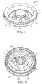
- FIG. 1 is a three-dimensional view of a burner cap according to a first embodiment of the present invention
- FIG. 2 is a three-dimensional bottom view of the burner cap according to the first embodiment of the present invention
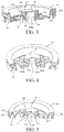
- FIG. 3 is a sectional view of the burner cap according to the first embodiment of the present invention
- FIG. 4 is a sectional view of the burner cap along another section according to the first embodiment of the present invention.
- a burner cap 3 of a burner used for a gas cooktop in this embodiment is an integrally formed member, and the burner cap 3 includes an inner ring cap portion 10 and an outer ring cap portion 20.
- the bottom of the inner ring cap portion 10 includes an inwardly concaved first concaved portion 11, the first concaved portion 11 is used for accommodating gas supplied by an inner ring gas jet, and the inner ring cap portion 10 is provided with a first gas outlet 101 in communication with the first concaved portion 11.
- the first gas outlet 101 includes an air outlet slot, the air outlet slot is a circular slot extending along a circumferential direction of an outer circumference surface of the inner ring cap portion 10, and the air outlet slot is provided with a plurality of connection holes 104 that communicates the air outlet slot and the first concaved portion 11.
- the outer ring cap portion 20 surrounds the periphery of the inner ring cap portion 10, the bottom of the outer ring cap portion 20 is inwardly concaved to form an outer ring concaved portion 21, and the outer ring concaved portion 21 is used for accommodating gas supplied by an outer ring gas jet.
- the first concaved portion 11 is separated from the outer ring concaved portion 21.
- the outer ring cap portion 20 is provided with an outer ring gas outlet 201 and an outer ring gas outlet 202 in communication with the outer ring concaved portion 21.
- the outer ring gas outlet 201 includes a plurality of air outlet holes distributed along a circumferential direction of the outer ring cap portion 20.
- the outer ring gas outlet 202 includes an air outlet slot extending along the circumferential direction of the outer ring cap portion 20.
- the air outlet slot is disposed with a plurality of connection holes 203 that communicates the air outlet slot and the outer ring concaved portion 21.
- the inner ring cap portion 10 is further provided with a second gas outlet 102, and the second gas outlet 102 includes a plurality of air outlet holes.
- the first gas outlet 101 and the second gas outlet 102 are formed on a same smooth surface on the inner ring cap portion 10, that is, on an outer circumference surface 10b.
- an outer edge of a vertical projection of the first gas outlet 101 and an outer edge of a vertical projection of the second gas outlet 102 are on a same circumference.
- the second gas outlet 102 is in communication with the outer ring concaved portion 21.
- the bottom of the inner ring cap portion 10 in this embodiment further includes an inwardly concaved second concaved portion 12.
- the second concaved portion 12 is disposed on the periphery of the first concaved portion 11.
- the second concaved portion 12 is separated from the first concaved portion 11, the second concaved portion 12 is in communication with the outer ring concaved portion 21, and the second gas outlet 102 is in communication with the second concaved portion 12. Therefore, in a use state of the burner cap, the second gas outlet 102 is in communication with the outer ring concaved portion 21.
- the inner ring cap portion 10 includes a wall body potion 100 surrounding the first concaved portion 11, the wall body potion 100 is provided with a plurality of connection channels 103 that communicates the second gas outlet 102 and the second concaved portion 12, and the plurality of connection channels 103 is a plurality of connection holes distributed along a circumferential direction of the wall body potion 100.
- the wall body potion 100 further includes a protruding extension portion 100a, and the extension portion 100a is disposed to separate the first concaved portion 11 from the second concaved portion 12 in a use state of the burner cap 3. This will be described in the following.
- the total area of all first gas outlets 101 on the burner cap 3 is less than the total area of all second gas outlets 102. Therefore, flames burning in the second gas outlet 102 supplied with gas by the outer ring gas injector form main flames on the inner ring cap portion 10, and flames burning in the first gas outlet 101 supplied with gas by the inner ring gas injector form booster flames, to play an effect of stabilizing burning of the main flames.
- the burner cap in this embodiment may burn more sufficiently when the outer ring cap portion has flames, the heat efficiency may reach 69% to 70%, and the emission of burned CO in the burner cap can be reduced; and when the burner cap is at the minimum fire, the power is small enough.
- the burner cap 3 further includes at least one connection portion 15 connected between the outer ring cap portion 20 and the inner ring cap portion 10.
- the connection portion 15 forms a component of a gas guide channel used for communicating the outer ring concaved portion 21 and the second concaved portion 12.
- the burner cap 3 in this embodiment includes three connection portions 15, each connection portion 15 includes a connection slot 150, and the connection slot 150 communicates the outer ring concaved portion 21 and the second concaved portion 12.
- the first gas outlet 101 further includes an air outlet hole 101a corresponding to a thermocouple, an air outlet hole 101c on the upper side of the thermocouple, an air outlet hole 101b corresponding to an ignition needle, and an air outlet hole 101d on the upper side of the ignition needle, to ensure the ignition performance and the security protection performance of the burner cap 3.
- FIG. 5 is a sectional view of a burner cap according to a second embodiment of the present invention
- FIG. 6 is a three-dimensional bottom view of the burner cap according to the second embodiment of the present invention.
- portion structures and functions corresponding to same numbers of the burner cap are same as or similar to those in the first embodiment. To avoid repetition, details are not described herein again, and reference is made to related descriptions in the first embodiment.
- the difference from the first embodiment is: The total area of all first gas outlets 101 on the burner cap in this embodiment is greater than the total area of all second gas outlets 102.
- the first gas outlet 101 includes a plurality of air outlet holes distributed along a circumferential direction of the inner ring cap portion 10.
- the second gas outlet 102 includes an air outlet slot, and the air outlet slot is an air outlet slot extending along a circumferential direction of an outer circumference surface of the inner ring cap portion 10.
- the wall body potion 100 is provided with a plurality of connection channels 103 that communicates the second gas outlet 102 and the second concaved portion 12.
- the plurality of connection channels 103 is a plurality of connection holes distributed along a circumferential direction of the wall body potion 100, so that the air outlet slot is in communication with the second concaved portion 12.
- the heat efficiency of the burner cap in this embodiment is lower than that in the first embodiment, compared with the existing burner cap, when the outer ring cap portion has flames, the burning is more sufficiently, and the emission of burned CO in the burner cap can be reduced; and when the burner cap is at the minimum fire, the power is smaller compared with the existing burner cap.
- the inner ring cap portion includes an inner ring seat and a top cap detachably covered on the inner ring seat.
- the outer ring cap portion, the connection portion, and the inner ring seat form an integrally formed member.
- FIG. 7 and FIG. 8 further show a burner head 2 of a burner used for a gas cooktop.
- FIG. 7 is an exploded view of a burner head according to an embodiment of the present invention.
- FIG. 8 is a three-dimensional view of a burner head according to an embodiment of the present invention.
- the burner head 2 includes a burner cap base 4 and a burner cap 3, and the burner cap 3 is detachably covered on the burner cap base 4.
- the burner cap 3 may be the burner cap described in the previous embodiment.
- the first concaved portion 11 matches the burner cap base 4 to form an inner ring gas mixing chamber 13 (as shown in FIG. 12 and FIG. 13 )
- the outer ring concaved portion 21 matches the burner cap base 4 to form an outer ring gas mixing chamber 23.
- the outer ring gas mixing chamber 23 is separated from the inner ring gas mixing chamber 13.
- FIG. 9 is a three-dimensional view of a burner cap base according to an embodiment of the present invention.
- the burner cap base 4 in this embodiment includes an inner ring gas inlet 41 and an outer ring gas inlet 42, the inner ring gas inlet 41 is used for allowing gas supplied by an inner ring gas injector to enter the burner head 2, and the outer ring gas inlet 42 is used for allowing gas supplied by an outer ring gas injector to enter the burner head 2.
- the center region of the burner cap base 4 includes a barrel portion 40, and an inlet of the barrel portion 40 forms the inner ring gas inlet 41.
- the barrel portion 40 matches a portion forming the first concaved portion 11 to form an inner ring gas mixing chamber 13, that is, the barrel portion 40 is seamlessly matched with the wall body potion 100 to form the inner ring gas mixing chamber 13, that is, the barrel portion 40 is seamlessly matched with the extension portion 100a to form the inner ring gas mixing chamber 13. Therefore, in a use state of the burner cap 3, the first concaved portion 11 is separated from the outer ring concaved portion 21.
- the burner cap base 4 includes an outer ring wall 44 and a plurality of air inlets 46 located at an inner side of the outer ring wall 44. As shown in FIG. 1, FIG. 2 , and FIG. 6 , the burner cap 3 is provided with a plurality of air outlets 16 separately corresponding to a plurality of air inlets 46. The air inlet 46 matches the air outlet 16 to form an air channel. Air enters the air channel from the lower side of the burner head 2 to supplement secondary air to burning of the burner head 2.
- the burner cap base 4 includes a plurality of fence portions 45 disposed at intervals, each of the fence portions 45 fences an air inlet 46, and two neighboring fence portions 45 form a gas guide slot 43.
- the fence portion 45 and the outer ring wall 44 form a groove 47, and the gas guide slot 43 communicates the outer ring gas inlet 42 and the groove 47.
- the groove 47 matches the outer ring concaved portion 21 to form an outer ring gas mixing chamber 23 (as shown in FIG. 12 and FIG. 13 )
- the gas guide slot 43 matches the connection slot 150 on the burner cap 3 to form a gas guide channel
- the gas guide channel communicates the outer ring gas inlet 42 and the outer ring gas mixing chamber 23.
- a second concaved portion 12 on the burner cap 3 faces toward the outer ring gas inlet 42. Therefore, in a use state of the stove, after gas enters from the outer ring gas inlet 42, the second concaved portion 12 accommodates the gas, and the gas enters the outer ring gas mixing chamber 23 from the gas guide channel.
- the burner cap base 4 in this embodiment is an integrally formed member, and is manufactured in a forging manner by using a brass material same as the burner cap 3. To reduce a tolerance accumulation in a manufacture process, and prevent that after the burner cap 3 is covered on the burner cap base 4, separated inner ring gas mixing chamber and outer ring gas mixing chamber cannot be formed, for example, a matching location of the barrel portion 40 and the extension portion 100a leaks gas.
- An upper surface of the barrel portion 40 in this embodiment and an upper surface of a portion forming the gas guide slot 43 are on a same plane, that is, the upper surface of the barrel portion 40 and an upper surface of the fence portion 45 are on a same plane.
- the burner cap base 4 further includes a plurality of flow division portions 420, and the flow division portion 420 is connected between an outer wall of the barrel portion 40 and a wall forming the outer ring gas inlet 42.
- the outer ring gas inlet 42 is divided into a plurality of gas division openings by the flow division portion 420, and each gas guide slot 43 corresponds to at least one of the flow division portions 420.
- the burner cap base 4 includes three flow division portions 420, the outer ring gas inlet 42 is divided into three gas division openings 42a, 42b, and 42c by the flow division portion 420, and a gas flow of the outer ring gas inlet 42 is divided into three gas flows.
- Each gas guide slot 43 corresponds to one flow division portion 420, and each flow division portion 420 directly faces toward the center location of one gas guide slot 43. That is, the flow division portion 420 extends in a straight line, and an extension direction of each flow division portion 420 coincides with a symmetry axis of the corresponding gas guide slot 43.
- an extension direction of the flow division portion 420 is perpendicular to a direction of an air flow of gas at the outer ring gas inlet 42. Therefore, a part of gas from the gas division opening 42a and a part of gas from the gas division opening 42b are mixed to enter the gas guide slot 43 in the right upper side of FIG. 9 , and then enter the groove 47.
- this is described from one single aspect of the burner cap base 4. In an actual use state of the stove, a part of gas from the gas division opening 42a and a part of gas from the gas division opening 42b are mixed to enter the outer ring gas mixing chamber 23 from the gas guide channel corresponding to the gas guide slot 43 in the right upper side in FIG. 9 .
- the flow division portion 420 is disposed to perform a first division, which is equivalent to increasing the resistance at the outer ring gas inlet 42, and having effects of pressure reduction and flow rate reduction for entered gas flows.
- Each gas guide slot 43 corresponds to a flow division portion 420, which is equivalent to a second division performed to divide the previous multiple air flows to be transferred into the gas guide slot 43, so that division is performed twice before the gas flows enter the outer ring gas mixing chamber, and the gas entering the outer ring gas mixing chamber 23 is more even.
- the burner cap base 4 includes an inner ring gas flow channel and an outer ring gas flow channel
- the barrel portion 40 forms the inner ring gas flow channel
- the outer ring gas flow channel includes the outer ring gas inlet 42, the gas guide slot 43, and the groove 47.
- the inner ring gas flow channel is separated from the outer ring gas flow channel.
- the burner cap matching the burner cap base 4 in the embodiment shown in FIG. 9 may be the burner cap 3 described in the previous embodiment, or may be any burner cap that may match the burner cap base 4.
- the burner cap base matching the burner cap 3 in the embodiment shown in FIG. 1 to FIG. 6 may be the burner cap base show in FIG. 9 , or may be any burner cap base that may match the burner cap 3.
- the burner cap base 4 in this embodiment is provided with a burner cap location column 48
- the burner cap 3 is provided with a burner cap location hole 14 corresponding to the burner cap location column 48, as shown in FIG. 2 and FIG. 6 .
- the burner cap location hole is disposed on the burner cap base, so that after a spill or dirt enters the burner cap base, the spill or dirt may fall into the burner cap location hole and fill some height, and the burner cap location column cannot be completely inserted into place. Therefore, the burner cap cannot be covered on the burner cap base seamlessly, and a crack leaks gas. The crack that leaks gas may form flames, and after a long time, the burner cap may be burned to deform.
- This embodiment can avoid the foregoing problems, and even though the spill or dirt enters the burner cap base, the spill or dirt does not cause any impact to the fastening of the burner cap.
- the present invention further shows a burner head 2 of a burner used for a gas cooktop, including an outer ring gas mixing chamber 23 and an inner ring gas mixing chamber 13 that are separated.
- the outer ring gas mixing chamber 23 is used for accommodating gas supplied by an outer ring gas injector 521 (shown in FIG. 12 and FIG. 13 ), and the inner ring gas mixing chamber 13 is used for accommodating gas supplied by an inner ring gas injector 511.
- the burner head 2 includes an outer ring gas outlet 201 and an outer ring gas outlet 202 distributed on an outer ring region of the burner head 2.
- the outer ring gas outlet 201 and the outer ring gas outlet 202 are separately in communication with the outer ring gas mixing chamber 23.
- the burner head 2 further includes a first gas outlet 101 and a second gas outlet 102 distributed on an inner ring region of the burner head 2.
- the first gas outlet 101 is in communication with the inner ring gas mixing chamber 13, and the second gas outlet 102 is in communication with the outer ring gas mixing chamber 23.
- the burner head 2 in an embodiment is formed by separated assembly, such as the burner head described in the previous embodiment. Details are not described herein again.
- the burner head 2 is an integrally formed member, and the entire burner head may be integrally manufactured by using the existing processing technology.
- the present invention shows a burner 1 used for a gas cooktop, including the burner head 2 according to any one of the foregoing embodiments.
- FIG. 10 is an exploded view of a burner according to an embodiment of the present invention
- FIG. 11 is a three-dimensional view of a burner according to an embodiment of the present invention.
- the burner 1 includes a burner base 5, and the burner head 2 is detachably placed on the burner base 5.
- the burner base 5 includes an inner ring injection system 51, an outer ring injection system 52, a thermocouple 53, and an ignition needle 54.
- the inner ring injection system 51 includes an inner ring gas injector 511, an inner ring induction tube 512 connected to the inner ring gas injector 511, and an inner ring pressure stabilizing cavity 513 connected to the inner ring induction tube 512.
- the outer ring injection system 52 includes an outer ring gas injector 521, an outer ring induction tube 522 connected to the outer ring gas injector 521, and an outer ring pressure stabilizing cavity 523 connected to the outer ring induction tube 522.
- the inner ring pressure stabilizing cavity 513 is in communication with an inner ring gas mixing chamber 13 or a first concaved portion 11.
- the outer ring pressure stabilizing cavity 523 is in communication with an outer ring gas mixing chamber 23 or an outer ring concaved portion 21.
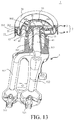
- FIG. 12 is a sectional view of a burner according to a first embodiment of the present invention. To show more structure features, FIG. 12 does not use an ordinary sectioning method along one section.
- the burner 1 shown in this embodiment uses the burner cap 3 described in the first embodiment. For some related descriptions, refer to the previous descriptions.
- the burner cap 3 includes an inner ring cap portion 10 and an outer ring cap portion 20.
- the bottom of the inner ring cap portion 10 includes an inwardly concaved first concaved portion 11, a wall body potion 100 surrounding the first concaved portion 11 matches a barrel portion 40 of the burner cap base 4 to form the inner ring gas mixing chamber 13.
- Gas supplied by the inner ring gas injector 511 and primary air inhaled from the front end of the inner ring induction tube 512 enter the inner ring induction tube 512, subsequently reach the inner ring pressure stabilizing cavity 513, and then enter the inner ring gas mixing chamber 13 from the inner ring gas inlet 41.
- the outer ring cap portion 20 surrounds the periphery of the inner ring cap portion 10, the bottom of the outer ring cap portion 20 is inwardly concaved to form an outer ring concaved portion 21, and the outer ring concaved portion 21 matches a groove 47 on the burner cap base 4 to form the outer ring gas mixing chamber 23.
- Gas supplied by an outer ring gas injector 521 and primary air inhaled from the front end of the outer ring induction tube 522 enter the outer ring induction tube 522, subsequently reach the outer ring pressure stabilizing cavity 523, and then enter the outer ring gas mixing chamber 23 from the outer ring gas inlet 42.
- the outer ring cap portion 20 is provided with an outer ring gas outlet 201 and an outer ring gas outlet 202 in communication with the outer ring concaved portion 21.
- the bottom of the inner ring cap portion 10 further includes an inwardly concaved second concaved portion 12, and the second concaved portion 12 is disposed on the periphery of the first concaved portion 11.
- the second concaved portion 12 is in communication with both the outer ring gas inlet 42 and the outer ring gas mixing chamber 23.
- the inner ring cap portion 10 is provided with a first gas outlet 101 in communication with the first concaved portion 11.
- the first gas outlet 101 includes an air outlet slot.
- the inner ring cap portion 10 is further provided with a second gas outlet 102 in communication with the second concaved portion, and the second gas outlet 102 includes a plurality of air outlet holes.
- the total area of all first gas outlets 101 on the burner cap 3 is less than the total area of all second gas outlets 102.
- FIG. 13 is a sectional view of a burner according to the second embodiment of the present invention.
- the burner 1 shown in this embodiment uses the burner cap 3 described in the previous second embodiment.
- portion structures and functions corresponding to same numbers of the burner are same as or similar to those in the first embodiment. To avoid repetition, details are not described herein again, and reference is made to related descriptions in the first embodiment.
- the difference from the first embodiment is:
- the total area of all first gas outlets 101 on the burner cap used by the burner in this embodiment is greater than the total area of all second gas outlets 102.
- the first gas outlet 101 includes a plurality of air outlet holes distributed along a circumferential direction of the inner ring cap portion 10, and the second gas outlet 102 includes an air outlet slot.
- the present invention further provides a gas cooktop, including the burner 1 used for a gas cooktop according to any one of the foregoing embodiments.
Landscapes
- Engineering & Computer Science (AREA)
- Chemical & Material Sciences (AREA)
- Combustion & Propulsion (AREA)
- Mechanical Engineering (AREA)
- General Engineering & Computer Science (AREA)
- Gas Burners (AREA)
Claims (14)
- Brennerdeckelsockel (4) für einen Brenner (1) einer Gaskochstelle mit einem Außenring-Gaseinlass (42) und einer Nut (47) zum Aufnehmen von Gas, wobei der Außenring-Gaseinlass (42) dazu dient, dass von einer Außenring-Gasdüse (521) zugeführtes Gas in den Brennerdeckelsockel (4) hineinströmen kann, wobei der Brennerdeckelsockel (4) ferner mehrere Gasführungsschlitze (43) umfasst, die jeweils die Nut (47) und den Außenring-Gaseinlass (42) miteinander verbinden, wobei der Brennerdeckelsockel (4) ferner mehrere Strömungsaufteilabschnitte (420) umfasst, wobei der Außenring-Gaseinlass (42) durch die Strömungsaufteilabschnitte (420) in mehrere Gasaufteilöffnungen (42a, 42b, 42c) aufgeteilt ist,
dadurch gekennzeichnet, dass jeder Gasführungsschlitz (43) mindestens einem Strömungsaufteilabschnitt (420) entspricht, und wobei jeder Strömungsaufteilabschnitt (420) direkt zur Mitte eines der Gasführungsschlitze (43) weist. - Brennerdeckelsockel (4) nach Anspruch 1, dadurch gekennzeichnet, dass er mehrere Lufteinlässe (46) umfasst, wobei der Brennerdeckelsockel (4) mehrere in Abständen angeordnete Umgrenzungsabschnitte (45) umfasst, von denen jeder einen der Lufteinlässe (46) umgrenzt, und zwei benachbarte Umgrenzungsabschnitte (45) den Gasführungsschlitz (43) bilden.
- Brennerdeckelsockel (4) nach Anspruch 2, dadurch gekennzeichnet, dass er eine umlaufende Außenringwand (44) umfasst, wobei sich der Umgrenzungsabschnitt (45) an einer Innenseite der Außenringwand (44) befindet und die Außenringwand (44) und der Umgrenzungsabschnitt (45) die Nut (47) bilden.
- Brennerdeckelsockel (4) nach einem der Ansprüche 1 bis 3, dadurch gekennzeichnet, dass er drei Strömungsaufteilabschnitte (420) umfasst, wobei der Außenring-Gaseinlass (42) in drei Gasaufteilöffnungen (42a, 42b, 42c) aufgeteilt ist.
- Brennerdeckelsockel (4) nach einem der Ansprüche 1 bis 3, dadurch gekennzeichnet, dass er ferner einen Innenring-Gaseinlass (41) umfasst, wobei der Innenring-Gaseinlass (41) dazu dient, dass von einer Innenring-Gasdüse (511) zugeführtes Gas in den Brenner (1) hineinströmen kann, der Brennerdeckelsockel (4) einen Zylinderabschnitt (40) umfasst, ein Einlass des Zylinderabschnitts (40) den Innenring-Gaseinlass (41) bildet und der Strömungsaufteilabschnitt (420) als Verbindung zwischen einer Außenwand des Zylinderabschnitts (40) und einer den Außenring-Gaseinlass (42) bildenden Wand dient.
- Brennerdeckelsockel (4) nach Anspruch 5, dadurch gekennzeichnet, dass er einen Innenring-Gasströmungskanal und einen Außenring-Gasströmungskanal umfasst, wobei der Zylinderabschnitt (40) den Innenring-Gasströmungskanal bildet und der Außenring-Gasströmungskanal den Außenring-Gaseinlass (42), den Gasführungsschlitz (43) und die Nut (47) umfasst und der Innenring-Gasströmungskanal in einem Gebrauchszustand des Brennerdeckelsockels (4) von dem Außenring-Gasströmungskanal getrennt ist.
- Brennerdeckelsockel (4) nach Anspruch 5, dadurch gekennzeichnet, dass sich eine obere Fläche des Zylinderabschnitts (40) und eine obere Fläche eines Abschnitts, der den Gasführungsschlitz (43) bildet, auf der gleichen Ebene befinden.
- Brennerdeckelsockel (4) nach einem der Ansprüche 1 bis 7, dadurch gekennzeichnet, dass es sich bei dem Brennerdeckelsockel (4) um ein einstückig gebildetes Element handelt.
- Brennerkopf (2) für einen Brenner (1) einer Gaskochstelle, dadurch gekennzeichnet, dass er eine Brennerkappe (3) und den Brennerdeckelsockel (4) nach einem der vorhergehenden Ansprüche umfasst, wobei die Brennerkappe (3) den Brennerdeckelsockel (4) abnehmbar abdeckt.
- Brennerkopf (2) nach Anspruch 9, dadurch gekennzeichnet, dass die Brennerkappe (3) einen Innenring-Deckelabschnitt (10) und einen den Umfang des Innenring-Deckelabschnitts (10) umgebenden Außenring-Deckelabschnitt (20) umfasst, wobei die Unterseite des Außenring-Deckelabschnitts (20) nach innen hin konkav ist, so dass sie einen konkaven Außenringabschnitt (21) bildet, der so zu der Nut (47) passt, dass eine Außenring-Gasmischkammer (23) entsteht, die zum Aufnehmen von von einer Außenring-Gasdüse (521) zugeführtem Gas dient, und der Außenring-Deckelabschnitt (20) mit einem Außenring-Gasauslass (201, 202) versehen ist, der mit der Außenring-Gasmischkammer (23) verbunden ist, und die Unterseite des Innenring-Deckelabschnitts (10) einen nach innen hin konkaven ersten konkaven Abschnitt (11) umfasst, der so zu dem Brennerdeckelsockel (4) passt, dass eine Innenring-Gasmischkammer (13) entsteht, die zum Aufnehmen von von einer Innenring-Gasdüse (511) zugeführtem Gas dient, wobei der Innenring-Deckelabschnitt (10) mit einem ersten Gasauslass (101) versehen ist, der mit der Innenring-Gasmischkammer (13) verbunden ist, wobei der Innenring-Deckelabschnitt (10) ferner mit einem zweiten Gasauslass (102) versehen ist und der zweite Gasauslass (102) mit der Außenring-Gasmischkammer (23) verbunden ist.
- Brennerkopf (2) nach Anspruch 10, dadurch gekennzeichnet, dass der erste Gasauslass (101) und der zweite Gasauslass (102) an der gleichen eben verlaufenden Fläche an dem Innenring-Deckelabschnitt (10) gebildet sind.
- Brennerkopf (2) nach Anspruch 10, dadurch gekennzeichnet, dass die Brennerkappe (3) ferner einen Verbindungsabschnitt (15) umfasst, der als Verbindung zwischen dem Außenring-Deckelabschnitt (20) und dem Innenring-Deckelabschnitt (10) dient, wobei der Verbindungsabschnitt (15) zu dem Gasführungsschlitz (43) passt, so dass ein Gasführungskanal entsteht, und der Gasführungskanal den Außenring-Gaseinlass (42) und die Außenring-Gasmischkammer (23) miteinander verbindet.
- Brenner (1) für eine Gaskochstelle, dadurch gekennzeichnet, dass er den Brennerkopf (2) nach einem der Ansprüche 9 bis 12 umfasst.
- Gaskochstelle, dadurch gekennzeichnet, dass sie den Brenner (1) nach Anspruch 13 umfasst.
Applications Claiming Priority (4)
| Application Number | Priority Date | Filing Date | Title |
|---|---|---|---|
| CN201710337805.9A CN108870390B (zh) | 2017-05-15 | 2017-05-15 | 燃气灶及燃气灶用燃烧器的火盖、炉头、燃烧器 |
| CN201720540394.9U CN206989200U (zh) | 2017-05-15 | 2017-05-15 | 燃气灶用燃烧器的炉头、燃烧器及燃气灶 |
| CN201710337518.8A CN108870389B (zh) | 2017-05-15 | 2017-05-15 | 燃气灶用燃烧器的火盖、炉头、燃烧器及燃气灶 |
| CN201710337617.6A CN108870395B (zh) | 2017-05-15 | 2017-05-15 | 燃气灶用燃烧器的火盖底座、炉头、燃烧器及燃气灶 |
Publications (2)
| Publication Number | Publication Date |
|---|---|
| EP3404325A1 EP3404325A1 (de) | 2018-11-21 |
| EP3404325B1 true EP3404325B1 (de) | 2020-09-16 |
Family
ID=62167234
Family Applications (2)
| Application Number | Title | Priority Date | Filing Date |
|---|---|---|---|
| EP18172353.7A Active EP3404324B1 (de) | 2017-05-15 | 2018-05-15 | Brennerdeckel für brenner eines gaskochfelds, brennerkopf, brenner und gaskochfeld |
| EP18172364.4A Active EP3404325B1 (de) | 2017-05-15 | 2018-05-15 | Deckelsockel für brenner eines gaskochfelds, brenner und gaskochfeld |
Family Applications Before (1)
| Application Number | Title | Priority Date | Filing Date |
|---|---|---|---|
| EP18172353.7A Active EP3404324B1 (de) | 2017-05-15 | 2018-05-15 | Brennerdeckel für brenner eines gaskochfelds, brennerkopf, brenner und gaskochfeld |
Country Status (1)
| Country | Link |
|---|---|
| EP (2) | EP3404324B1 (de) |
Families Citing this family (7)
| Publication number | Priority date | Publication date | Assignee | Title |
|---|---|---|---|---|
| CN111911921B (zh) * | 2019-05-09 | 2025-02-18 | 宁波方太厨具有限公司 | 一种用于燃气灶的燃烧器 |
| CN110388667B (zh) * | 2019-07-19 | 2024-03-19 | 华帝股份有限公司 | 用于燃气灶具的盛液盘的固定结构 |
| CN111853788B (zh) * | 2020-07-17 | 2022-07-12 | 海信(广东)厨卫系统有限公司 | 一种平板式燃烧器及平板式燃气灶 |
| CN113124402B (zh) * | 2021-04-13 | 2025-01-24 | 火星人厨具股份有限公司 | 一种桥式防干烧喷嘴座及其运作方法 |
| CN113685815A (zh) * | 2021-07-28 | 2021-11-23 | 宁波方太厨具有限公司 | 上进风燃烧器 |
| CN115704560A (zh) * | 2021-08-03 | 2023-02-17 | 芜湖美的智能厨电制造有限公司 | 一种燃气炉头及燃气灶 |
| CN115681969B (zh) * | 2022-09-27 | 2025-07-04 | 宁波方太厨具有限公司 | 燃烧器及包含其的灶具 |
Family Cites Families (6)
| Publication number | Priority date | Publication date | Assignee | Title |
|---|---|---|---|---|
| IT1258754B (it) * | 1992-01-13 | 1996-02-27 | Smeg Spa | Bruciatore perfezionato per fornelli di cottura a gas a tre fiamme concentriche |
| US5875974A (en) * | 1998-04-10 | 1999-03-02 | Ranco Of Delaware | Wave washer port ring gas top burner |
| US6132205A (en) * | 2000-01-06 | 2000-10-17 | Harneit; Uwe | Multi-ring sealed gas burner |
| IT1320580B1 (it) * | 2000-08-02 | 2003-12-10 | Smeg Spa | Bruciatore ultrarapido per piano di cottura o per una cucina a gas. |
| ITVE20050004A1 (it) * | 2005-01-20 | 2006-07-21 | Ohg Defendi S R L | Bruciatore a gas per apparecchiature di cottura. |
| US20150107577A1 (en) * | 2013-10-18 | 2015-04-23 | Lg Electronics Inc. | Burner |
-
2018
- 2018-05-15 EP EP18172353.7A patent/EP3404324B1/de active Active
- 2018-05-15 EP EP18172364.4A patent/EP3404325B1/de active Active
Non-Patent Citations (1)
| Title |
|---|
| None * |
Also Published As
| Publication number | Publication date |
|---|---|
| EP3404325A1 (de) | 2018-11-21 |
| EP3404324B1 (de) | 2020-09-30 |
| EP3404324A1 (de) | 2018-11-21 |
Similar Documents
| Publication | Publication Date | Title |
|---|---|---|
| EP3404325A1 (de) | Brennerdeckelsockel für gaskochfeld, herd, brenner und gaskochfeld | |
| CN108870390B (zh) | 燃气灶及燃气灶用燃烧器的火盖、炉头、燃烧器 | |
| WO2016141643A1 (zh) | 底杯盖及燃烧器及燃气用具 | |
| WO2016141644A1 (zh) | 燃烧器及燃气用具 | |
| CN108613183A (zh) | 一种引射管隐藏式灶具燃烧器 | |
| CN110410786B (zh) | 一种灶具燃烧器 | |
| CN111735052B (zh) | 火盖、燃烧器及燃气灶具 | |
| US11441781B2 (en) | System of gas burners, in particular for a cooking top for household use | |
| US20130252183A1 (en) | Gas burner with at least three rings | |
| EP3339731B1 (de) | Gasbrenner und kochfeld mit einem gasbrenner | |
| CN206989200U (zh) | 燃气灶用燃烧器的炉头、燃烧器及燃气灶 | |
| CN108870395A (zh) | 燃气灶用燃烧器的火盖底座、炉头、燃烧器及燃气灶 | |
| CN108870389B (zh) | 燃气灶用燃烧器的火盖、炉头、燃烧器及燃气灶 | |
| CN111878812B (zh) | 火盖、燃烧器和灶具 | |
| CN109000246B (zh) | 燃烧器及燃气灶具 | |
| CN214581069U (zh) | 燃烧器及燃气灶 | |
| CN109959007B (zh) | 一种用于燃气灶的燃烧器火盖以及应用有该燃烧器火盖的燃烧器 | |
| CN112254131B (zh) | 外环火盖、燃烧器及燃气灶具 | |
| EP3591289B1 (de) | Zweikreisbrenner, gasbrenneranordnung und gasherd | |
| EP4449019B1 (de) | Brennerkopf für ein kochfeld, brenner und kochfeld | |
| CN109140445B (zh) | 火盖组件、燃烧器及燃气灶 | |
| CN215723201U (zh) | 一种燃烧器以及灶具 | |
| JP4103114B2 (ja) | バーナ装置 | |
| CN115234909A (zh) | 一种分火器及其燃烧器 | |
| CN112577047B (zh) | 燃气灶的燃烧器与燃气灶 |
Legal Events
| Date | Code | Title | Description |
|---|---|---|---|
| PUAI | Public reference made under article 153(3) epc to a published international application that has entered the european phase |
Free format text: ORIGINAL CODE: 0009012 |
|
| STAA | Information on the status of an ep patent application or granted ep patent |
Free format text: STATUS: THE APPLICATION HAS BEEN PUBLISHED |
|
| AK | Designated contracting states |
Kind code of ref document: A1 Designated state(s): AL AT BE BG CH CY CZ DE DK EE ES FI FR GB GR HR HU IE IS IT LI LT LU LV MC MK MT NL NO PL PT RO RS SE SI SK SM TR |
|
| AX | Request for extension of the european patent |
Extension state: BA ME |
|
| STAA | Information on the status of an ep patent application or granted ep patent |
Free format text: STATUS: REQUEST FOR EXAMINATION WAS MADE |
|
| 17P | Request for examination filed |
Effective date: 20190521 |
|
| RBV | Designated contracting states (corrected) |
Designated state(s): AL AT BE BG CH CY CZ DE DK EE ES FI FR GB GR HR HU IE IS IT LI LT LU LV MC MK MT NL NO PL PT RO RS SE SI SK SM TR |
|
| GRAP | Despatch of communication of intention to grant a patent |
Free format text: ORIGINAL CODE: EPIDOSNIGR1 |
|
| STAA | Information on the status of an ep patent application or granted ep patent |
Free format text: STATUS: GRANT OF PATENT IS INTENDED |
|
| INTG | Intention to grant announced |
Effective date: 20200504 |
|
| GRAS | Grant fee paid |
Free format text: ORIGINAL CODE: EPIDOSNIGR3 |
|
| GRAA | (expected) grant |
Free format text: ORIGINAL CODE: 0009210 |
|
| STAA | Information on the status of an ep patent application or granted ep patent |
Free format text: STATUS: THE PATENT HAS BEEN GRANTED |
|
| AK | Designated contracting states |
Kind code of ref document: B1 Designated state(s): AL AT BE BG CH CY CZ DE DK EE ES FI FR GB GR HR HU IE IS IT LI LT LU LV MC MK MT NL NO PL PT RO RS SE SI SK SM TR |
|
| REG | Reference to a national code |
Ref country code: GB Ref legal event code: FG4D |
|
| REG | Reference to a national code |
Ref country code: CH Ref legal event code: EP |
|
| REG | Reference to a national code |
Ref country code: DE Ref legal event code: R096 Ref document number: 602018007814 Country of ref document: DE |
|
| REG | Reference to a national code |
Ref country code: IE Ref legal event code: FG4D |
|
| REG | Reference to a national code |
Ref country code: AT Ref legal event code: REF Ref document number: 1314484 Country of ref document: AT Kind code of ref document: T Effective date: 20201015 |
|
| PG25 | Lapsed in a contracting state [announced via postgrant information from national office to epo] |
Ref country code: FI Free format text: LAPSE BECAUSE OF FAILURE TO SUBMIT A TRANSLATION OF THE DESCRIPTION OR TO PAY THE FEE WITHIN THE PRESCRIBED TIME-LIMIT Effective date: 20200916 Ref country code: GR Free format text: LAPSE BECAUSE OF FAILURE TO SUBMIT A TRANSLATION OF THE DESCRIPTION OR TO PAY THE FEE WITHIN THE PRESCRIBED TIME-LIMIT Effective date: 20201217 Ref country code: NO Free format text: LAPSE BECAUSE OF FAILURE TO SUBMIT A TRANSLATION OF THE DESCRIPTION OR TO PAY THE FEE WITHIN THE PRESCRIBED TIME-LIMIT Effective date: 20201216 Ref country code: SE Free format text: LAPSE BECAUSE OF FAILURE TO SUBMIT A TRANSLATION OF THE DESCRIPTION OR TO PAY THE FEE WITHIN THE PRESCRIBED TIME-LIMIT Effective date: 20200916 Ref country code: BG Free format text: LAPSE BECAUSE OF FAILURE TO SUBMIT A TRANSLATION OF THE DESCRIPTION OR TO PAY THE FEE WITHIN THE PRESCRIBED TIME-LIMIT Effective date: 20201216 Ref country code: HR Free format text: LAPSE BECAUSE OF FAILURE TO SUBMIT A TRANSLATION OF THE DESCRIPTION OR TO PAY THE FEE WITHIN THE PRESCRIBED TIME-LIMIT Effective date: 20200916 |
|
| REG | Reference to a national code |
Ref country code: AT Ref legal event code: MK05 Ref document number: 1314484 Country of ref document: AT Kind code of ref document: T Effective date: 20200916 |
|
| REG | Reference to a national code |
Ref country code: NL Ref legal event code: MP Effective date: 20200916 |
|
| PG25 | Lapsed in a contracting state [announced via postgrant information from national office to epo] |
Ref country code: LV Free format text: LAPSE BECAUSE OF FAILURE TO SUBMIT A TRANSLATION OF THE DESCRIPTION OR TO PAY THE FEE WITHIN THE PRESCRIBED TIME-LIMIT Effective date: 20200916 Ref country code: RS Free format text: LAPSE BECAUSE OF FAILURE TO SUBMIT A TRANSLATION OF THE DESCRIPTION OR TO PAY THE FEE WITHIN THE PRESCRIBED TIME-LIMIT Effective date: 20200916 |
|
| REG | Reference to a national code |
Ref country code: LT Ref legal event code: MG4D |
|
| PG25 | Lapsed in a contracting state [announced via postgrant information from national office to epo] |
Ref country code: LT Free format text: LAPSE BECAUSE OF FAILURE TO SUBMIT A TRANSLATION OF THE DESCRIPTION OR TO PAY THE FEE WITHIN THE PRESCRIBED TIME-LIMIT Effective date: 20200916 Ref country code: SM Free format text: LAPSE BECAUSE OF FAILURE TO SUBMIT A TRANSLATION OF THE DESCRIPTION OR TO PAY THE FEE WITHIN THE PRESCRIBED TIME-LIMIT Effective date: 20200916 Ref country code: EE Free format text: LAPSE BECAUSE OF FAILURE TO SUBMIT A TRANSLATION OF THE DESCRIPTION OR TO PAY THE FEE WITHIN THE PRESCRIBED TIME-LIMIT Effective date: 20200916 Ref country code: RO Free format text: LAPSE BECAUSE OF FAILURE TO SUBMIT A TRANSLATION OF THE DESCRIPTION OR TO PAY THE FEE WITHIN THE PRESCRIBED TIME-LIMIT Effective date: 20200916 Ref country code: PT Free format text: LAPSE BECAUSE OF FAILURE TO SUBMIT A TRANSLATION OF THE DESCRIPTION OR TO PAY THE FEE WITHIN THE PRESCRIBED TIME-LIMIT Effective date: 20210118 Ref country code: CZ Free format text: LAPSE BECAUSE OF FAILURE TO SUBMIT A TRANSLATION OF THE DESCRIPTION OR TO PAY THE FEE WITHIN THE PRESCRIBED TIME-LIMIT Effective date: 20200916 |
|
| PG25 | Lapsed in a contracting state [announced via postgrant information from national office to epo] |
Ref country code: AL Free format text: LAPSE BECAUSE OF FAILURE TO SUBMIT A TRANSLATION OF THE DESCRIPTION OR TO PAY THE FEE WITHIN THE PRESCRIBED TIME-LIMIT Effective date: 20200916 Ref country code: AT Free format text: LAPSE BECAUSE OF FAILURE TO SUBMIT A TRANSLATION OF THE DESCRIPTION OR TO PAY THE FEE WITHIN THE PRESCRIBED TIME-LIMIT Effective date: 20200916 Ref country code: ES Free format text: LAPSE BECAUSE OF FAILURE TO SUBMIT A TRANSLATION OF THE DESCRIPTION OR TO PAY THE FEE WITHIN THE PRESCRIBED TIME-LIMIT Effective date: 20200916 Ref country code: IS Free format text: LAPSE BECAUSE OF FAILURE TO SUBMIT A TRANSLATION OF THE DESCRIPTION OR TO PAY THE FEE WITHIN THE PRESCRIBED TIME-LIMIT Effective date: 20210116 Ref country code: PL Free format text: LAPSE BECAUSE OF FAILURE TO SUBMIT A TRANSLATION OF THE DESCRIPTION OR TO PAY THE FEE WITHIN THE PRESCRIBED TIME-LIMIT Effective date: 20200916 |
|
| REG | Reference to a national code |
Ref country code: DE Ref legal event code: R097 Ref document number: 602018007814 Country of ref document: DE |
|
| PG25 | Lapsed in a contracting state [announced via postgrant information from national office to epo] |
Ref country code: SK Free format text: LAPSE BECAUSE OF FAILURE TO SUBMIT A TRANSLATION OF THE DESCRIPTION OR TO PAY THE FEE WITHIN THE PRESCRIBED TIME-LIMIT Effective date: 20200916 |
|
| PLBE | No opposition filed within time limit |
Free format text: ORIGINAL CODE: 0009261 |
|
| STAA | Information on the status of an ep patent application or granted ep patent |
Free format text: STATUS: NO OPPOSITION FILED WITHIN TIME LIMIT |
|
| 26N | No opposition filed |
Effective date: 20210617 |
|
| PG25 | Lapsed in a contracting state [announced via postgrant information from national office to epo] |
Ref country code: DK Free format text: LAPSE BECAUSE OF FAILURE TO SUBMIT A TRANSLATION OF THE DESCRIPTION OR TO PAY THE FEE WITHIN THE PRESCRIBED TIME-LIMIT Effective date: 20200916 Ref country code: SI Free format text: LAPSE BECAUSE OF FAILURE TO SUBMIT A TRANSLATION OF THE DESCRIPTION OR TO PAY THE FEE WITHIN THE PRESCRIBED TIME-LIMIT Effective date: 20200916 |
|
| REG | Reference to a national code |
Ref country code: DE Ref legal event code: R119 Ref document number: 602018007814 Country of ref document: DE |
|
| REG | Reference to a national code |
Ref country code: CH Ref legal event code: PL |
|
| PG25 | Lapsed in a contracting state [announced via postgrant information from national office to epo] |
Ref country code: CH Free format text: LAPSE BECAUSE OF NON-PAYMENT OF DUE FEES Effective date: 20210531 Ref country code: LI Free format text: LAPSE BECAUSE OF NON-PAYMENT OF DUE FEES Effective date: 20210531 Ref country code: MC Free format text: LAPSE BECAUSE OF FAILURE TO SUBMIT A TRANSLATION OF THE DESCRIPTION OR TO PAY THE FEE WITHIN THE PRESCRIBED TIME-LIMIT Effective date: 20200916 Ref country code: LU Free format text: LAPSE BECAUSE OF NON-PAYMENT OF DUE FEES Effective date: 20210515 |
|
| REG | Reference to a national code |
Ref country code: BE Ref legal event code: MM Effective date: 20210531 |
|
| PG25 | Lapsed in a contracting state [announced via postgrant information from national office to epo] |
Ref country code: IE Free format text: LAPSE BECAUSE OF NON-PAYMENT OF DUE FEES Effective date: 20210515 Ref country code: DE Free format text: LAPSE BECAUSE OF NON-PAYMENT OF DUE FEES Effective date: 20211201 |
|
| PG25 | Lapsed in a contracting state [announced via postgrant information from national office to epo] |
Ref country code: FR Free format text: LAPSE BECAUSE OF NON-PAYMENT OF DUE FEES Effective date: 20210531 |
|
| PG25 | Lapsed in a contracting state [announced via postgrant information from national office to epo] |
Ref country code: BE Free format text: LAPSE BECAUSE OF NON-PAYMENT OF DUE FEES Effective date: 20210531 |
|
| GBPC | Gb: european patent ceased through non-payment of renewal fee |
Effective date: 20220515 |
|
| PG25 | Lapsed in a contracting state [announced via postgrant information from national office to epo] |
Ref country code: GB Free format text: LAPSE BECAUSE OF NON-PAYMENT OF DUE FEES Effective date: 20220515 |
|
| PG25 | Lapsed in a contracting state [announced via postgrant information from national office to epo] |
Ref country code: NL Free format text: LAPSE BECAUSE OF NON-PAYMENT OF DUE FEES Effective date: 20200923 Ref country code: CY Free format text: LAPSE BECAUSE OF FAILURE TO SUBMIT A TRANSLATION OF THE DESCRIPTION OR TO PAY THE FEE WITHIN THE PRESCRIBED TIME-LIMIT Effective date: 20200916 |
|
| PG25 | Lapsed in a contracting state [announced via postgrant information from national office to epo] |
Ref country code: HU Free format text: LAPSE BECAUSE OF FAILURE TO SUBMIT A TRANSLATION OF THE DESCRIPTION OR TO PAY THE FEE WITHIN THE PRESCRIBED TIME-LIMIT; INVALID AB INITIO Effective date: 20180515 |
|
| PGFP | Annual fee paid to national office [announced via postgrant information from national office to epo] |
Ref country code: IT Payment date: 20230531 Year of fee payment: 6 |
|
| PGFP | Annual fee paid to national office [announced via postgrant information from national office to epo] |
Ref country code: TR Payment date: 20230510 Year of fee payment: 6 |
|
| PG25 | Lapsed in a contracting state [announced via postgrant information from national office to epo] |
Ref country code: MK Free format text: LAPSE BECAUSE OF FAILURE TO SUBMIT A TRANSLATION OF THE DESCRIPTION OR TO PAY THE FEE WITHIN THE PRESCRIBED TIME-LIMIT Effective date: 20200916 |
|
| PG25 | Lapsed in a contracting state [announced via postgrant information from national office to epo] |
Ref country code: MT Free format text: LAPSE BECAUSE OF FAILURE TO SUBMIT A TRANSLATION OF THE DESCRIPTION OR TO PAY THE FEE WITHIN THE PRESCRIBED TIME-LIMIT Effective date: 20200916 |
|
| PG25 | Lapsed in a contracting state [announced via postgrant information from national office to epo] |
Ref country code: IT Free format text: LAPSE BECAUSE OF NON-PAYMENT OF DUE FEES Effective date: 20240515 |