EP3404334A1 - Energiespeicherverfahren und -anlage, die einen wasserboiler umfasst - Google Patents
Energiespeicherverfahren und -anlage, die einen wasserboiler umfasst Download PDFInfo
- Publication number
- EP3404334A1 EP3404334A1 EP18173151.4A EP18173151A EP3404334A1 EP 3404334 A1 EP3404334 A1 EP 3404334A1 EP 18173151 A EP18173151 A EP 18173151A EP 3404334 A1 EP3404334 A1 EP 3404334A1
- Authority
- EP
- European Patent Office
- Prior art keywords
- water
- energy
- surplus
- water heater
- heater
- Prior art date
- Legal status (The legal status is an assumption and is not a legal conclusion. Google has not performed a legal analysis and makes no representation as to the accuracy of the status listed.)
- Granted
Links
Images


Classifications
-
- F—MECHANICAL ENGINEERING; LIGHTING; HEATING; WEAPONS; BLASTING
- F24—HEATING; RANGES; VENTILATING
- F24D—DOMESTIC- OR SPACE-HEATING SYSTEMS, e.g. CENTRAL HEATING SYSTEMS; DOMESTIC HOT-WATER SUPPLY SYSTEMS; ELEMENTS OR COMPONENTS THEREFOR
- F24D17/00—Domestic hot-water supply systems
- F24D17/0026—Domestic hot-water supply systems with conventional heating means
- F24D17/0031—Domestic hot-water supply systems with conventional heating means with accumulation of the heated water
-
- F—MECHANICAL ENGINEERING; LIGHTING; HEATING; WEAPONS; BLASTING
- F24—HEATING; RANGES; VENTILATING
- F24D—DOMESTIC- OR SPACE-HEATING SYSTEMS, e.g. CENTRAL HEATING SYSTEMS; DOMESTIC HOT-WATER SUPPLY SYSTEMS; ELEMENTS OR COMPONENTS THEREFOR
- F24D17/00—Domestic hot-water supply systems
- F24D17/02—Domestic hot-water supply systems using heat pumps
-
- F—MECHANICAL ENGINEERING; LIGHTING; HEATING; WEAPONS; BLASTING
- F24—HEATING; RANGES; VENTILATING
- F24D—DOMESTIC- OR SPACE-HEATING SYSTEMS, e.g. CENTRAL HEATING SYSTEMS; DOMESTIC HOT-WATER SUPPLY SYSTEMS; ELEMENTS OR COMPONENTS THEREFOR
- F24D19/00—Details
- F24D19/10—Arrangement or mounting of control or safety devices
- F24D19/1006—Arrangement or mounting of control or safety devices for water heating systems
- F24D19/1051—Arrangement or mounting of control or safety devices for water heating systems for domestic hot water
- F24D19/1054—Arrangement or mounting of control or safety devices for water heating systems for domestic hot water the system uses a heat pump
-
- F—MECHANICAL ENGINEERING; LIGHTING; HEATING; WEAPONS; BLASTING
- F24—HEATING; RANGES; VENTILATING
- F24H—FLUID HEATERS, e.g. WATER OR AIR HEATERS, HAVING HEAT-GENERATING MEANS, e.g. HEAT PUMPS, IN GENERAL
- F24H15/00—Control of fluid heaters
- F24H15/10—Control of fluid heaters characterised by the purpose of the control
- F24H15/174—Supplying heated water with desired temperature or desired range of temperature
-
- F—MECHANICAL ENGINEERING; LIGHTING; HEATING; WEAPONS; BLASTING
- F24—HEATING; RANGES; VENTILATING
- F24H—FLUID HEATERS, e.g. WATER OR AIR HEATERS, HAVING HEAT-GENERATING MEANS, e.g. HEAT PUMPS, IN GENERAL
- F24H15/00—Control of fluid heaters
- F24H15/20—Control of fluid heaters characterised by control inputs
- F24H15/212—Temperature of the water
- F24H15/223—Temperature of the water in the water storage tank
-
- F—MECHANICAL ENGINEERING; LIGHTING; HEATING; WEAPONS; BLASTING
- F24—HEATING; RANGES; VENTILATING
- F24H—FLUID HEATERS, e.g. WATER OR AIR HEATERS, HAVING HEAT-GENERATING MEANS, e.g. HEAT PUMPS, IN GENERAL
- F24H15/00—Control of fluid heaters
- F24H15/30—Control of fluid heaters characterised by control outputs; characterised by the components to be controlled
- F24H15/355—Control of heat-generating means in heaters
- F24H15/37—Control of heat-generating means in heaters of electric heaters
-
- F—MECHANICAL ENGINEERING; LIGHTING; HEATING; WEAPONS; BLASTING
- F24—HEATING; RANGES; VENTILATING
- F24H—FLUID HEATERS, e.g. WATER OR AIR HEATERS, HAVING HEAT-GENERATING MEANS, e.g. HEAT PUMPS, IN GENERAL
- F24H15/00—Control of fluid heaters
- F24H15/30—Control of fluid heaters characterised by control outputs; characterised by the components to be controlled
- F24H15/375—Control of heat pumps
- F24H15/38—Control of compressors of heat pumps
-
- F—MECHANICAL ENGINEERING; LIGHTING; HEATING; WEAPONS; BLASTING
- F24—HEATING; RANGES; VENTILATING
- F24D—DOMESTIC- OR SPACE-HEATING SYSTEMS, e.g. CENTRAL HEATING SYSTEMS; DOMESTIC HOT-WATER SUPPLY SYSTEMS; ELEMENTS OR COMPONENTS THEREFOR
- F24D2200/00—Heat sources or energy sources
- F24D2200/02—Photovoltaic energy
-
- F—MECHANICAL ENGINEERING; LIGHTING; HEATING; WEAPONS; BLASTING
- F24—HEATING; RANGES; VENTILATING
- F24D—DOMESTIC- OR SPACE-HEATING SYSTEMS, e.g. CENTRAL HEATING SYSTEMS; DOMESTIC HOT-WATER SUPPLY SYSTEMS; ELEMENTS OR COMPONENTS THEREFOR
- F24D2200/00—Heat sources or energy sources
- F24D2200/08—Electric heater
-
- F—MECHANICAL ENGINEERING; LIGHTING; HEATING; WEAPONS; BLASTING
- F24—HEATING; RANGES; VENTILATING
- F24D—DOMESTIC- OR SPACE-HEATING SYSTEMS, e.g. CENTRAL HEATING SYSTEMS; DOMESTIC HOT-WATER SUPPLY SYSTEMS; ELEMENTS OR COMPONENTS THEREFOR
- F24D2200/00—Heat sources or energy sources
- F24D2200/12—Heat pump
-
- F—MECHANICAL ENGINEERING; LIGHTING; HEATING; WEAPONS; BLASTING
- F24—HEATING; RANGES; VENTILATING
- F24H—FLUID HEATERS, e.g. WATER OR AIR HEATERS, HAVING HEAT-GENERATING MEANS, e.g. HEAT PUMPS, IN GENERAL
- F24H15/00—Control of fluid heaters
- F24H15/10—Control of fluid heaters characterised by the purpose of the control
- F24H15/144—Measuring or calculating energy consumption
- F24H15/152—Forecasting future energy consumption
-
- F—MECHANICAL ENGINEERING; LIGHTING; HEATING; WEAPONS; BLASTING
- F24—HEATING; RANGES; VENTILATING
- F24H—FLUID HEATERS, e.g. WATER OR AIR HEATERS, HAVING HEAT-GENERATING MEANS, e.g. HEAT PUMPS, IN GENERAL
- F24H15/00—Control of fluid heaters
- F24H15/20—Control of fluid heaters characterised by control inputs
- F24H15/262—Weather information or forecast
-
- F—MECHANICAL ENGINEERING; LIGHTING; HEATING; WEAPONS; BLASTING
- F24—HEATING; RANGES; VENTILATING
- F24H—FLUID HEATERS, e.g. WATER OR AIR HEATERS, HAVING HEAT-GENERATING MEANS, e.g. HEAT PUMPS, IN GENERAL
- F24H15/00—Control of fluid heaters
- F24H15/20—Control of fluid heaters characterised by control inputs
- F24H15/281—Input from user
-
- Y—GENERAL TAGGING OF NEW TECHNOLOGICAL DEVELOPMENTS; GENERAL TAGGING OF CROSS-SECTIONAL TECHNOLOGIES SPANNING OVER SEVERAL SECTIONS OF THE IPC; TECHNICAL SUBJECTS COVERED BY FORMER USPC CROSS-REFERENCE ART COLLECTIONS [XRACs] AND DIGESTS
- Y02—TECHNOLOGIES OR APPLICATIONS FOR MITIGATION OR ADAPTATION AGAINST CLIMATE CHANGE
- Y02B—CLIMATE CHANGE MITIGATION TECHNOLOGIES RELATED TO BUILDINGS, e.g. HOUSING, HOUSE APPLIANCES OR RELATED END-USER APPLICATIONS
- Y02B10/00—Integration of renewable energy sources in buildings
- Y02B10/70—Hybrid systems, e.g. uninterruptible or back-up power supplies integrating renewable energies
Definitions
- the subject of the invention is a method and an energy storage installation using a water heater supplied with energy by a photovoltaic system.
- photovoltaic systems have a wired output that can be connected to the water heater to control the heating of the water contained in the water heater. This type of system makes a heating demand when the power supplied by the photovoltaic panels exceeds a certain threshold. If the energy threshold is not reached, the latter is then sent back to the network at a loss.
- the object of the invention is to overcome the aforementioned drawbacks by a simple control means.
- the invention relates to an energy storage installation comprising: a water heating device for supplying a hot water room, the water heating device comprising: a water heater including: - a heating element for heating water contained in the water heater, - a thermometer for measuring a temperature of the water water contained in the water heater; and a regulator card connected to the heating member and to the thermometer, the regulator card regulating the heating member as a function of energy received by a photovoltaic system and of energy received by means other than the photovoltaic system, the control card being adapted to determine a heating power to be controlled by the heating member as a function of a temperature set point, the temperature setpoint having a base value Tbas, and a surplus value Tsur greater than or equal to the basic value Tbas; and an energy manager connected to the control board and to the photovoltaic system, the energy manager being adapted to communicate to the control board that a surplus of energy produced by the photovoltaic system is available, and when moreover the temperature of the water contained in the water heater is
- the energy storage facility it is possible to store in thermal form, in the water heater, electrical energy that would otherwise be injected at a loss into the network.
- the subject of the invention is also a control method in which, if the energy manager communicates to the control board that a surplus of energy is produced by the photovoltaic system, the control board controls the control unit. to heat the water using the energy produced by the surplus photovoltaic system, the heating power heating the water to a temperature equal to or lower than a surplus value of the temperature set Tsur, the surplus value of the temperature setpoint Tsur being greater than or equal to the base value of the temperature setpoint Tbas.
- An energy storage device using a water heater 12 supplying a room, for example a dwelling, with domestic hot water is referenced 10 on the figure 1 .
- the energy storage installation 10 includes a heating device water supply 14 for supplying the dwelling with hot water, an energy manager 15 in communication with the water heating device 14 for modulating the heating of the water, and a photovoltaic system 16 supplying the heating device water 14 energy for heating water.
- the water heating device 14 is also supplied with energy by the electrical network.
- the photovoltaic system 16 comprises one or more photovoltaic panels 18 which convert a received light into direct current, and a converter 19 which converts the direct current produced by the photovoltaic panels 18 into alternating current. It is understood that the converter 19 could be optional.
- the water heating device 14 comprises a water heater 12 controlled by a regulation card 22.
- the water heater 12 may be an electric or thermodynamic water heater.
- the water heater 12 could also have combined thermodynamic and electric heating elements.
- the water heater 12 includes a thermometer 13 making it possible to know a temperature of the water contained in the water heater 12, and a heating member 24 for heating water contained in the water heater 12 in particular according to commands issued from the regulation card 22.
- the heating member 24 would for example be a heat pump with variable compressor speed.
- the heating member 24 would include for example one or more resistors (fixed or variable) connected to one or more pins. An example of a heater 24 for an electric water heater will be described below in conjunction with the figure 2 .
- the regulation card 22 is an electronic card which has several logic inputs in order to modulate the heating power of the heating member 24 as a function of the surplus of photovoltaic energy produced.
- the regulation card 22 includes a calculation module 23, which is in communication with the energy manager 15 and the thermometer 13.
- the calculation module 23 makes it possible to determine when to heat the water of the water heater 12 (in particular by the data of the thermometer 13), but also to regulate the contributions in energy between the electrical energy of the network and that produced by the photovoltaic system 16, in order to optimize the input of photovoltaic energy.
- the calculation module 23 determines a heating power based on at least the possible surplus of photovoltaic energy, the water temperature in the water heater 12 and a temperature setpoint.
- the temperature setpoint is a reference temperature at which the water in the water heater 12 must be (i.e. maximum heating temperature).
- the temperature setpoint has several values depending on whether a surplus of photovoltaic energy is present.
- a basic value of the temperature setpoint is a maximum temperature allowed by the user for the water delivered to him. For example, if the user desires a maximum temperature of 55 degrees Celsius, the base value of the temperature setpoint will be 55 degrees.
- the basic value of the temperature setpoint could be transmitted to the control board 22 by the user via an interface (for example a keyboard).
- the temperature setpoint also has a high value, surplus value Tsur, which is greater than or equal to the base value and which is the maximum temperature attainable when an excess of photovoltaic energy is available.
- Tsur surplus value
- the regulator board 22 heats the water in order to convert the surplus of photovoltaic energy into thermal energy that can be used by the user instantaneously or in the near future.
- This temperature can be transmitted to the regulation board 22 by the user via the interface, or can be calculated by the control board as a function of the basic value of the temperature setpoint.
- the surplus value of the temperature set Tsur is for example 70 degrees Celsius.
- the installation 10 may include a thermostatic mixing valve connected to the water heater 12.
- the mixing valve could, for example, be at the outlet of the water heater 12.
- the thermostatic mixing valve is adapted to deliver the water from the water heater 12 to a water heater 12. temperature scale based on the base value of the temperature setpoint Tbas.
- the thermostatic mixing valve can deliver the water of the water heater 12 at a maximum temperature equal to the basic value of the temperature setpoint even if the water temperature of the water heater 12 is at a temperature above the value basic, for example when it is at surplus value.
- the heating power determined by the calculation module 22 transmits the transmits to the heating member 24 to heat water correspondingly.
- thermometer 13 makes it possible to check whether the water reaches the temperature setpoint and to stop the heating at that moment, via the regulation card 22.
- the energy manager 15 in cooperation with the regulation card 22 makes it possible to store a surplus of energy produced by the photovoltaic panels 18 in thermal energy. Indeed, in some cases, it may be that the photovoltaic system 16 produces more energy than the water heater 14 (and possibly also the electrical appliances 20) require. With the installation and method described below, at least a portion of this surplus of photovoltaic energy produced can be reinjected into the water heater 14 instead of being injected at a loss to the supply network. Thus, the energy that should have been returned to the grid (thus at a loss) is transformed into heat energy by heating the water of the water heater in addition to its usual operation. The water heating device 14 then functions as a storage of energy, by converting surplus electrical energy produced by the photovoltaic system 16 into thermal energy (heated water). If the surplus is greater than the heating capacity of the water heater, the difference could be fed back into the network.
- the energy manager 15 compares the energy produced by the photovoltaic panels 18 with the energy consumed by the dwelling.
- the energy manager 15 may, for example, receive different microinverter signals from the photovoltaic panels 18.
- a torus on a network line connected to a counter 26 of the room determines an energy produced by the photovoltaic system 16 and not consumed.
- Linky counters or another could be used.
- the energy manager 15 could be integrated with the photovoltaic system 16.
- the energy manager 15 transmits a signal to the control board 22.
- the signal could be a voltage or intensity signal depending on the recipient of this signal. This signal is for example a 0 / 230V signal.
- the energy manager 15 may not communicate wireline.
- a radio link could be used between the energy manager 15 and the control card 22.
- the energy manager 15 could also regulate, in cooperation with the control card 22, the function of the water heater 12 depending on other factors than the surplus of photovoltaic energy immediately available.
- the water heater 12 could heat the water exclusively with the surplus production of the panels during the daytime periods. Thus energy storage would be favored. If the heating of the balloon is carried out in daytime by the use of the photovoltaic energy, the energy of the network could be used only to manage the lacks in hot. Outside of the daytime period (i.e. night period), the water heater 12 could be allowed to use power from the power grid.
- the water heater 12 is allowed to use the energy of the network even during the production periods of the photovoltaic panels 18, that is to say, even during the daytime periods.
- the night mode of operation can be anticipated at the end of the day phase (ie, the night mode of operation is activated in the daytime period before sunset) if the energy production Photovoltaic was low in the day.
- This mode of operation could prevent users from having cold water at the end of the day if the sun is insufficient, and thus improve the comfort of users.
- the system could then use the energy of the network to compensate for the lack of photovoltaic so that the user has hot water at the end of the day.
- the energy manager 15 and / or the control card 22 could be connected to a server or a cloud to receive, for example, meteorological data, in particular for integrating the daily sunning forecasts to use the additional resistance or resistors. if the production potential of the photovoltaic panels 18 is insufficient during the day.
- the energy manager 15 could also take into account the consumption habits of the dwelling to regulate the use of the surplus photovoltaic energy.
- the energy manager 15 and / or the control card 22 could record the consumption over the last 24 hours and deduce a user profile to determine hot water requirements to be provided at certain time slots.
- the basic value of the temperature setpoint could then vary over time to allow storage of hot water before the usual consumption periods according to the user profile.
- the regulation board 30 and the heating member 32 can be used in this example in conjunction with an electric water heater.
- the regulation card 30 includes a calculation module 31, and three relays 34 (I1, I2, I3).
- the relays 34 are each connected to a respective resistor 36 (R1, R2, R3).
- the calculation module 31 has determined the heating power to be controlled by the heating element 24, it selects the resistors 36 to be activated by actuating one or a combination of the relays 34.
- Each of the resistors 36 has an associated value, so that the activation of one, two or three of these three resistors 36 gives seven possibilities of combined resistances, and therefore heating power.
- the resistance R1 can produce a power of 1600W
- the resistance R2 of 800W and the resistance R3 of 400W
- the use (1 - in the table below) or the non-use (0 - in the table below) of this resistance according to the others gives the seven values of total power Ptotal: R1 (1600W) R2 (800W) R3 (400W) Ptotal (W) 0 0 0 0 1 0 0 1600 1 1 0 2400 1 1 1 2800 0 1 0 800 0 0 1 400 0 1 1 1200
- the energy manager 15 determines that a power of 2400W is surplus (after having supplied the appliances 20 and the water heater 12 in normal use), and that this power can be stored by heating the water of the heater. water 12 beyond its normal use temperature, the energy manager 15 sends, via the calculation module 31, a command to the control card 30 to close the relays I1 and I2 corresponding to the resistors R1 and R3, and to open the relay I3 corresponding to the resistance I3.
- the heater member 32 could have only one, or two or more than three resistors 36, and thus only one, two or more than three associated relays 34. In the case where the heater member 32 has two resistors 36, there would potentially be four associated powers. It is also noted that some or all of the resistors 36 could have the same value, or different values. Moreover, at least one of the resistors 36 could be a variable resistor. The heating member 32 could have a single variable resistor or a combination of variable and fixed resistors.
- a regulator card 40 controls the heater member 42.
- the heater member 42 is a heat pump with variable compressor speed.
- the regulation card 40 modulates the heater 42 by controlling a frequency of the compressor.
- the regulation board 40 modulates the compressor 42 continuously, that is to say without increments (unlike the arrangement of resistors 36 described above which gave only up to seven discrete values of heating power ) according to a command of the calculation module 41.
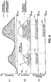
- the figure 4 shows an example of energy produced by the photovoltaic system 16 (solid line) and energy consumed (dotted line) over a period of time, for the systems described in figures 2 or 3 .
- the graph G1 shows that the energy produced by the photovoltaic system 16 (continuous line) and the energy consumed by the dwelling (dashed line) vary with respect to each other. Thus, there are periods when there is more energy produced by the photovoltaic system 16 than energy consumed (i.e. surplus, shaded area). This surplus is also illustrated in graph G2 by a line of mixed dots.
- the energy manager 15 controls the control card 30 (or 40) so as to heat to this power.
- the available power is the surplus available at the threshold S1 for the entire duration of time for which the threshold S1 is reached (shaded parts P1).
- the regulation board 30 activates one of the resistors R1, R2, R3 which has a lower value and the closest to the power of the threshold S1.
- the regulation card 40 activates the compressor of the heat pump at a speed corresponding to the power of the threshold S1. In one embodiment, a lower threshold is greater than a rated speed of the compressor.
- the available power is the surplus available at the threshold S2 for the entire duration of time for which the threshold S2 is reached.
- the regulation card 40 activates the compressor at a speed corresponding to the power of the threshold S2.
- a maximum attainable threshold (for example the threshold S2) depends on the mechanical characteristics of the heating element 24.
- the system operates without stops such as the thresholds S1 and S2. This could for example be achieved with the compressor in the case of a thermodynamic water heater or with a variable resistor so that they have their scalable power in real time depending on the fluctuation of the surplus. It could also be that the system operates in a discrete way (ie with steps) only for certain powers or at certain times of the day, and so continue for the rest.
- the energy storage method starts with a monitoring of the water temperature contained in the water heater 12 by the thermometer 13. If the thermometer 13 measures a water temperature of water equal to or greater than a value of based on the temperature setpoint Tbas, the regulation board 22 does not control the heating element 24 as long as no surplus energy is produced by the photovoltaic system 16. That is to say that if the water water heater 12 is already hot enough and there is no photovoltaic surplus (or the photovoltaic surplus is so small that it does not allow energy storage in thermal form), there is There is no need to heat the water further.
- the regulation board 22 controls the heating member 24 to heat the water itself. if the water is already at a temperature above the basic setpoint. It is possible that the excess energy available is lower than the minimum power value of the heating element 24, in which case the control card 22 does not control the heating member 24 to heat the water. .
- the control card 22 controls the heating member 24 to heat the water using the surplus, and this as far as the surplus is available, while being below the value surplus of Tsur temperature setpoint.
- the heating of the water is therefore done by the surplus photovoltaic energy (and not by the electrical energy of the network) which would otherwise be reinjected into the network (and thus lost).
- the surplus can be used to heat the water to the base value of the temperature or at a higher value (while being equal to or lower than the excess value of the temperature setpoint).
- the water heater 12 is used as a means of storing energy by storing the voltaic energy in hot water in anticipation of future consumption.
- the excess photovoltaic energy information is communicated to the regulator board 22 by the energy manager 15.
- the energy manager 15 determines a heating power corresponding to at least a portion of the surplus energy produced and not consumed by the photovoltaic system 16.
- the energy manager 15 takes into account the non-consumed energy information, but could also take into account other information, such as data on previous consumption profiles of the water heater. 12 (for example to ensure that they are in line with the energy availability prospects of photovoltaic panels 18 and avoid any use of the network, in order to approach or achieve a stand-alone water heater 12).
- the regulator card 22 sends the heating member 24 an activation command to the heating element 24 to the heating power to heat the water contained in the water heater 12.
- the control card 22 has several logic inputs, the logic inputs that make it possible to combine the resistors R1, R2, R3 (via the relays I1, I2, I3) so as to reach the available heating power, are activated.
- the regulation board 40 and the heat pump the regulation board 40 controls the compressor at a speed corresponding to the determined heating power.
- the heating power would be adjustable in real time depending on the surplus energy. In another embodiment, the heating power would be adjustable in increments of predetermined times (for example every five minutes).
- thermometer 13 measures a water temperature water contained in the water heater 12 lower than the base value of the temperature setpoint Tbas, and if the energy manager 15 communicates to the control card 22 that no excess energy is produced by the photovoltaic system 16, while the control card 22 controls the heating member 24 to heat the water to the base value of the temperature setpoint Tbas using other energy than that produced by the photovoltaic system 16, that is to say, the energy of the network.
- thermometer 13 measures a water temperature water contained in the water heater 12 lower than the base value of the temperature setpoint Tbas, and if the energy manager 15 communicates to the control card 22 that a excess energy is produced by the photovoltaic system 16, the control card 22 controls the heating member 24 to heat the water using the energy produced by the photovoltaic system 16 as a function of the surplus up to a value of surplus of the temperature setpoint Tsur, the excess value of the temperature setpoint Tsur being greater than or equal to the base value of the temperature setpoint Tbas.
- the control card 22 could control the heating member 24 so as to heat the water up to to the base value of the temperature setpoint Tbas by using, in addition to the energy from the photovoltaic surplus, energy other than that produced by the photovoltaic system 16, ie energy of the electricity network. This could especially be implemented during the night phases where the photovoltaic energy decreases.
- the installation 10 and the energy storage method described below make it possible to store a surplus of energy produced by the photovoltaic panels 18, which would otherwise be injected into the supply network, by thermal energy, in the form of heated water available in the water heater 12.
- the method is applicable to systems using electric and / or thermodynamic water heaters.
- the installation 10 can use simple components such as the relays I1, I2, I3 to effect the modulation of electrical power.
- the integration of the components used for the application of the method is minimal, and the installation 10 is adaptable to various environments, including implantable on existing water heaters.
Landscapes
- Engineering & Computer Science (AREA)
- Physics & Mathematics (AREA)
- Thermal Sciences (AREA)
- Chemical & Material Sciences (AREA)
- Combustion & Propulsion (AREA)
- Mechanical Engineering (AREA)
- General Engineering & Computer Science (AREA)
- Heat-Pump Type And Storage Water Heaters (AREA)
Applications Claiming Priority (1)
| Application Number | Priority Date | Filing Date | Title |
|---|---|---|---|
| FR1754477A FR3066582B1 (fr) | 2017-05-19 | 2017-05-19 | Procede et installation de stockage d'energie utilisant un chauffe-eau |
Publications (3)
| Publication Number | Publication Date |
|---|---|
| EP3404334A1 true EP3404334A1 (de) | 2018-11-21 |
| EP3404334B1 EP3404334B1 (de) | 2020-08-19 |
| EP3404334B2 EP3404334B2 (de) | 2023-08-09 |
Family
ID=59699824
Family Applications (1)
| Application Number | Title | Priority Date | Filing Date |
|---|---|---|---|
| EP18173151.4A Active EP3404334B2 (de) | 2017-05-19 | 2018-05-18 | Energiespeicherverfahren und -anlage, die einen wasserboiler umfasst |
Country Status (5)
| Country | Link |
|---|---|
| EP (1) | EP3404334B2 (de) |
| ES (1) | ES2829569T5 (de) |
| FR (1) | FR3066582B1 (de) |
| PL (1) | PL3404334T5 (de) |
| PT (1) | PT3404334T (de) |
Cited By (10)
| Publication number | Priority date | Publication date | Assignee | Title |
|---|---|---|---|---|
| EP3816524A1 (de) * | 2019-10-30 | 2021-05-05 | Atlantic Industrie | Vorrichtung zur wassererhitzung |
| US20220196251A1 (en) * | 2020-12-22 | 2022-06-23 | Premier Energy Holdings, Inc. | Device and Method for Converting Solar PV Energy into Thermal Energy Storage Using Combined Heat-Pump and Resistive Heating Elements in Water Heater |
| WO2022195007A1 (fr) | 2021-03-19 | 2022-09-22 | Wanit S.A. | Système de gestion d'une source a courant continu a puissance variable |
| FR3136539A1 (fr) * | 2022-06-13 | 2023-12-15 | Solarindep | Système de chauffage et/ou de climatisation |
| EP4355025A1 (de) * | 2022-10-11 | 2024-04-17 | BDR Thermea Group B.V. | Wärmepumpensystem mit zusätzlichem heizsystem und verfahren zur steuerung davon |
| CN118532982A (zh) * | 2023-02-23 | 2024-08-23 | 广东美的制冷设备有限公司 | 控制蓄热设备进行光伏消纳的方法、装置及能源控制装置 |
| EP4545867A1 (de) | 2023-10-27 | 2025-04-30 | BDR Thermea Group B.V. | Vorrichtung zum austausch von wärmeenergie zwischen einer wärmequelle und einem zweiten medium sowie verfahren zum betreiben einer solchen vorrichtung |
| EP3723239B1 (de) | 2019-03-08 | 2025-05-07 | Stiebel Eltron GmbH & Co. KG | Energiemanagementsystem zur steuerung eines häuslichen energieverbrauchs |
| WO2025167646A1 (zh) * | 2024-02-07 | 2025-08-14 | 广东美的暖通设备有限公司 | 一种储能控制方法、光伏热泵系统、设备和存储介质 |
| EP4589213A4 (de) * | 2022-09-27 | 2025-12-31 | Midea Group Co Ltd | Verfahren und vorrichtung zur steuerung eines fotovoltaischen wärmepumpenwassererhitzers sowie vorrichtung und speichermedium |
Citations (3)
| Publication number | Priority date | Publication date | Assignee | Title |
|---|---|---|---|---|
| US20140153913A1 (en) * | 2012-12-05 | 2014-06-05 | Energy Laboratories, Inc. | Solar Photovoltaic Water Heating System |
| US20150354833A1 (en) * | 2012-04-09 | 2015-12-10 | David Kreutzman | Renewable energy hot water heater with heat pump |
| EP3065021A1 (de) * | 2015-03-02 | 2016-09-07 | Electricité de France | Warmwasserheizsystem mit dedizierter fotovoltaikanlage |
Family Cites Families (2)
| Publication number | Priority date | Publication date | Assignee | Title |
|---|---|---|---|---|
| DE102011090141A1 (de) † | 2011-12-29 | 2013-07-04 | Werner Schmid | Verfahren und Vorrichtung zur Nutzung elektrischer Energie einer an ein Hausstromnetz angeschlossenen Einrichtung zur Erzeugung erneuerbarer elektrischer Energie |
| DE202013008096U1 (de) † | 2013-09-11 | 2013-09-24 | Klaus Rauch | Vorrichtung zur Regelung der Speicherung von elektrischer Energie in Form von Wärme |
-
2017
- 2017-05-19 FR FR1754477A patent/FR3066582B1/fr active Active
-
2018
- 2018-05-18 ES ES18173151T patent/ES2829569T5/es active Active
- 2018-05-18 PT PT181731514T patent/PT3404334T/pt unknown
- 2018-05-18 EP EP18173151.4A patent/EP3404334B2/de active Active
- 2018-05-18 PL PL18173151.4T patent/PL3404334T5/pl unknown
Patent Citations (3)
| Publication number | Priority date | Publication date | Assignee | Title |
|---|---|---|---|---|
| US20150354833A1 (en) * | 2012-04-09 | 2015-12-10 | David Kreutzman | Renewable energy hot water heater with heat pump |
| US20140153913A1 (en) * | 2012-12-05 | 2014-06-05 | Energy Laboratories, Inc. | Solar Photovoltaic Water Heating System |
| EP3065021A1 (de) * | 2015-03-02 | 2016-09-07 | Electricité de France | Warmwasserheizsystem mit dedizierter fotovoltaikanlage |
Cited By (15)
| Publication number | Priority date | Publication date | Assignee | Title |
|---|---|---|---|---|
| EP3723239B1 (de) | 2019-03-08 | 2025-05-07 | Stiebel Eltron GmbH & Co. KG | Energiemanagementsystem zur steuerung eines häuslichen energieverbrauchs |
| EP3816524A1 (de) * | 2019-10-30 | 2021-05-05 | Atlantic Industrie | Vorrichtung zur wassererhitzung |
| FR3102835A1 (fr) * | 2019-10-30 | 2021-05-07 | Atlantic Industrie | Dispositif de chauffage d’eau |
| US11867412B2 (en) * | 2020-12-22 | 2024-01-09 | Premier Energy Holdings, Inc. | Device and method for converting solar PV energy into thermal energy storage using combined heat-pump and resistive heating elements in water heater |
| WO2022140610A1 (en) * | 2020-12-22 | 2022-06-30 | Premier Energy Holdings, Inc. | Converting solar pv energy into thermal energy storage using heat-pump and resistive heating elements in water heater |
| US20220196251A1 (en) * | 2020-12-22 | 2022-06-23 | Premier Energy Holdings, Inc. | Device and Method for Converting Solar PV Energy into Thermal Energy Storage Using Combined Heat-Pump and Resistive Heating Elements in Water Heater |
| WO2022195007A1 (fr) | 2021-03-19 | 2022-09-22 | Wanit S.A. | Système de gestion d'une source a courant continu a puissance variable |
| FR3136539A1 (fr) * | 2022-06-13 | 2023-12-15 | Solarindep | Système de chauffage et/ou de climatisation |
| EP4589213A4 (de) * | 2022-09-27 | 2025-12-31 | Midea Group Co Ltd | Verfahren und vorrichtung zur steuerung eines fotovoltaischen wärmepumpenwassererhitzers sowie vorrichtung und speichermedium |
| EP4355025A1 (de) * | 2022-10-11 | 2024-04-17 | BDR Thermea Group B.V. | Wärmepumpensystem mit zusätzlichem heizsystem und verfahren zur steuerung davon |
| WO2024079024A1 (en) * | 2022-10-11 | 2024-04-18 | Bdr Thermea Group B.V. | Heat pump system with supplemental heating system and method for controlling thereof |
| CN118532982A (zh) * | 2023-02-23 | 2024-08-23 | 广东美的制冷设备有限公司 | 控制蓄热设备进行光伏消纳的方法、装置及能源控制装置 |
| CN118532982B (zh) * | 2023-02-23 | 2025-05-16 | 广东美的制冷设备有限公司 | 控制蓄热设备进行光伏消纳的方法、装置及能源控制装置 |
| EP4545867A1 (de) | 2023-10-27 | 2025-04-30 | BDR Thermea Group B.V. | Vorrichtung zum austausch von wärmeenergie zwischen einer wärmequelle und einem zweiten medium sowie verfahren zum betreiben einer solchen vorrichtung |
| WO2025167646A1 (zh) * | 2024-02-07 | 2025-08-14 | 广东美的暖通设备有限公司 | 一种储能控制方法、光伏热泵系统、设备和存储介质 |
Also Published As
| Publication number | Publication date |
|---|---|
| EP3404334B2 (de) | 2023-08-09 |
| ES2829569T5 (es) | 2024-03-26 |
| FR3066582A1 (fr) | 2018-11-23 |
| PL3404334T5 (pl) | 2023-12-04 |
| EP3404334B1 (de) | 2020-08-19 |
| ES2829569T3 (es) | 2021-06-01 |
| PT3404334T (pt) | 2020-11-09 |
| FR3066582B1 (fr) | 2021-02-12 |
| PL3404334T3 (pl) | 2021-03-22 |
Similar Documents
| Publication | Publication Date | Title |
|---|---|---|
| EP3404334B1 (de) | Energiespeicherverfahren und -anlage, die einen wasserboiler umfasst | |
| EP3117158B1 (de) | Elektro-wassererwärmer mit einstellbarer leistung | |
| EP3676541B1 (de) | Heizgerät mit einer batterie und einem wechselrichter zum zuführen von energie von der batterie in die elektrische versorgungsquelle | |
| FR2948780A1 (fr) | Gestion de l'energie dans un batiment | |
| FR3033391A1 (fr) | Systeme de chauffe-eau avec installation photovoltaique dediee | |
| WO2015158782A1 (fr) | Système de chauffe-eau à consommation énergétique modulable | |
| EP3161775A1 (de) | Leistungsverwaltungsverfahren in einer elektroinstallation und elektrische installation | |
| FR3098283A1 (fr) | Boîtier de régulation d’un ballon d’eau chaude et système de chauffe-eau solaire à ballon d’eau chaude | |
| CA3044348C (fr) | Appareil de chauffage de type radiateur electrique incluant un convertisseur de tension | |
| EP3650762B1 (de) | Kontrollverfahren einer thermischen leistung zum einspritzen in ein heizsystem, und dieses verfahren nutzendes heizsystem | |
| EP4308859B1 (de) | System zur verwaltung einer gleichstromquelle mit variabler leistung | |
| FR3104843A1 (fr) | Micro-réseau à équilibre perfectionné entre consommation et production | |
| WO2021140251A1 (fr) | Système et procédé de chauffage | |
| EP1008922B1 (de) | Verfahren zur Steuerung der Last mindestens einer Heizvorrichtung, insbesondere eines elektrischen Wärmespeichers, und/oder der thermischen Kapazität der Konstruktionsteile und der Ausrüstung; Vorrichtung zur Durchführung des Verfahrens | |
| EP2784896B1 (de) | System zur Steuerung der Stromerzeugung und des Stromverbrauchs | |
| FR3008484A1 (fr) | Installation de production energetique comprenant un dispositif de prediction meteorologique, notamment une installation de chauffe-eau solaire comprenant un tel dispositif | |
| EP2336679A1 (de) | Verfahren und Kontrolsystem einer Wärmepumpe mit thermoelektrischen Modulen | |
| EP2353054A2 (de) | Automatische steuereinrichtung für eine elektrische heizvorrichtung | |
| EP2886701B1 (de) | System zur Wassererwärmung und -versorgung der Verbraucher | |
| EP3671399A1 (de) | Bestimmungsverfahren eines bevorzugten minimalen leistungssollwerts, steuerungsverfahren einer vielzahl von wasserboilern und entsprechende vorrichtung | |
| EP4521030B1 (de) | System zur steuerung eines warmwasserbereitungsmittels | |
| FR3102835A1 (fr) | Dispositif de chauffage d’eau | |
| EP4603663A1 (de) | System und verfahren zur steuerung eines badebeckens, wie schwimmbecken oder spa | |
| FR2779024A1 (fr) | Installation de chauffage a convecteurs electriques | |
| EP4632524A1 (de) | Vorrichtung zur verbindung mit einem gebäudeheizregler |
Legal Events
| Date | Code | Title | Description |
|---|---|---|---|
| PUAI | Public reference made under article 153(3) epc to a published international application that has entered the european phase |
Free format text: ORIGINAL CODE: 0009012 |
|
| STAA | Information on the status of an ep patent application or granted ep patent |
Free format text: STATUS: THE APPLICATION HAS BEEN PUBLISHED |
|
| AK | Designated contracting states |
Kind code of ref document: A1 Designated state(s): AL AT BE BG CH CY CZ DE DK EE ES FI FR GB GR HR HU IE IS IT LI LT LU LV MC MK MT NL NO PL PT RO RS SE SI SK SM TR |
|
| AX | Request for extension of the european patent |
Extension state: BA ME |
|
| STAA | Information on the status of an ep patent application or granted ep patent |
Free format text: STATUS: REQUEST FOR EXAMINATION WAS MADE |
|
| 17P | Request for examination filed |
Effective date: 20190520 |
|
| RBV | Designated contracting states (corrected) |
Designated state(s): AL AT BE BG CH CY CZ DE DK EE ES FI FR GB GR HR HU IE IS IT LI LT LU LV MC MK MT NL NO PL PT RO RS SE SI SK SM TR |
|
| RAP1 | Party data changed (applicant data changed or rights of an application transferred) |
Owner name: ATLANTIC INDUSTRIE |
|
| GRAP | Despatch of communication of intention to grant a patent |
Free format text: ORIGINAL CODE: EPIDOSNIGR1 |
|
| STAA | Information on the status of an ep patent application or granted ep patent |
Free format text: STATUS: GRANT OF PATENT IS INTENDED |
|
| INTG | Intention to grant announced |
Effective date: 20200313 |
|
| GRAS | Grant fee paid |
Free format text: ORIGINAL CODE: EPIDOSNIGR3 |
|
| GRAA | (expected) grant |
Free format text: ORIGINAL CODE: 0009210 |
|
| STAA | Information on the status of an ep patent application or granted ep patent |
Free format text: STATUS: THE PATENT HAS BEEN GRANTED |
|
| AK | Designated contracting states |
Kind code of ref document: B1 Designated state(s): AL AT BE BG CH CY CZ DE DK EE ES FI FR GB GR HR HU IE IS IT LI LT LU LV MC MK MT NL NO PL PT RO RS SE SI SK SM TR |
|
| REG | Reference to a national code |
Ref country code: CH Ref legal event code: EP |
|
| REG | Reference to a national code |
Ref country code: DE Ref legal event code: R096 Ref document number: 602018006989 Country of ref document: DE |
|
| REG | Reference to a national code |
Ref country code: AT Ref legal event code: REF Ref document number: 1304362 Country of ref document: AT Kind code of ref document: T Effective date: 20200915 |
|
| REG | Reference to a national code |
Ref country code: IE Ref legal event code: FG4D Free format text: LANGUAGE OF EP DOCUMENT: FRENCH |
|
| REG | Reference to a national code |
Ref country code: PT Ref legal event code: SC4A Ref document number: 3404334 Country of ref document: PT Date of ref document: 20201109 Kind code of ref document: T Free format text: AVAILABILITY OF NATIONAL TRANSLATION Effective date: 20201030 |
|
| REG | Reference to a national code |
Ref country code: CH Ref legal event code: NV Representative=s name: VALIPAT S.A. C/O BOVARD SA NEUCHATEL, CH |
|
| REG | Reference to a national code |
Ref country code: LT Ref legal event code: MG4D |
|
| REG | Reference to a national code |
Ref country code: NL Ref legal event code: MP Effective date: 20200819 |
|
| PG25 | Lapsed in a contracting state [announced via postgrant information from national office to epo] |
Ref country code: GR Free format text: LAPSE BECAUSE OF FAILURE TO SUBMIT A TRANSLATION OF THE DESCRIPTION OR TO PAY THE FEE WITHIN THE PRESCRIBED TIME-LIMIT Effective date: 20201120 Ref country code: LT Free format text: LAPSE BECAUSE OF FAILURE TO SUBMIT A TRANSLATION OF THE DESCRIPTION OR TO PAY THE FEE WITHIN THE PRESCRIBED TIME-LIMIT Effective date: 20200819 Ref country code: HR Free format text: LAPSE BECAUSE OF FAILURE TO SUBMIT A TRANSLATION OF THE DESCRIPTION OR TO PAY THE FEE WITHIN THE PRESCRIBED TIME-LIMIT Effective date: 20200819 Ref country code: BG Free format text: LAPSE BECAUSE OF FAILURE TO SUBMIT A TRANSLATION OF THE DESCRIPTION OR TO PAY THE FEE WITHIN THE PRESCRIBED TIME-LIMIT Effective date: 20201119 Ref country code: SE Free format text: LAPSE BECAUSE OF FAILURE TO SUBMIT A TRANSLATION OF THE DESCRIPTION OR TO PAY THE FEE WITHIN THE PRESCRIBED TIME-LIMIT Effective date: 20200819 Ref country code: FI Free format text: LAPSE BECAUSE OF FAILURE TO SUBMIT A TRANSLATION OF THE DESCRIPTION OR TO PAY THE FEE WITHIN THE PRESCRIBED TIME-LIMIT Effective date: 20200819 Ref country code: NO Free format text: LAPSE BECAUSE OF FAILURE TO SUBMIT A TRANSLATION OF THE DESCRIPTION OR TO PAY THE FEE WITHIN THE PRESCRIBED TIME-LIMIT Effective date: 20201119 |
|
| PG25 | Lapsed in a contracting state [announced via postgrant information from national office to epo] |
Ref country code: RS Free format text: LAPSE BECAUSE OF FAILURE TO SUBMIT A TRANSLATION OF THE DESCRIPTION OR TO PAY THE FEE WITHIN THE PRESCRIBED TIME-LIMIT Effective date: 20200819 Ref country code: LV Free format text: LAPSE BECAUSE OF FAILURE TO SUBMIT A TRANSLATION OF THE DESCRIPTION OR TO PAY THE FEE WITHIN THE PRESCRIBED TIME-LIMIT Effective date: 20200819 Ref country code: NL Free format text: LAPSE BECAUSE OF FAILURE TO SUBMIT A TRANSLATION OF THE DESCRIPTION OR TO PAY THE FEE WITHIN THE PRESCRIBED TIME-LIMIT Effective date: 20200819 Ref country code: IS Free format text: LAPSE BECAUSE OF FAILURE TO SUBMIT A TRANSLATION OF THE DESCRIPTION OR TO PAY THE FEE WITHIN THE PRESCRIBED TIME-LIMIT Effective date: 20201219 |
|
| PG25 | Lapsed in a contracting state [announced via postgrant information from national office to epo] |
Ref country code: SM Free format text: LAPSE BECAUSE OF FAILURE TO SUBMIT A TRANSLATION OF THE DESCRIPTION OR TO PAY THE FEE WITHIN THE PRESCRIBED TIME-LIMIT Effective date: 20200819 Ref country code: EE Free format text: LAPSE BECAUSE OF FAILURE TO SUBMIT A TRANSLATION OF THE DESCRIPTION OR TO PAY THE FEE WITHIN THE PRESCRIBED TIME-LIMIT Effective date: 20200819 Ref country code: CZ Free format text: LAPSE BECAUSE OF FAILURE TO SUBMIT A TRANSLATION OF THE DESCRIPTION OR TO PAY THE FEE WITHIN THE PRESCRIBED TIME-LIMIT Effective date: 20200819 Ref country code: DK Free format text: LAPSE BECAUSE OF FAILURE TO SUBMIT A TRANSLATION OF THE DESCRIPTION OR TO PAY THE FEE WITHIN THE PRESCRIBED TIME-LIMIT Effective date: 20200819 Ref country code: RO Free format text: LAPSE BECAUSE OF FAILURE TO SUBMIT A TRANSLATION OF THE DESCRIPTION OR TO PAY THE FEE WITHIN THE PRESCRIBED TIME-LIMIT Effective date: 20200819 |
|
| REG | Reference to a national code |
Ref country code: AT Ref legal event code: UEP Ref document number: 1304362 Country of ref document: AT Kind code of ref document: T Effective date: 20200819 |
|
| REG | Reference to a national code |
Ref country code: DE Ref legal event code: R026 Ref document number: 602018006989 Country of ref document: DE |
|
| PLBI | Opposition filed |
Free format text: ORIGINAL CODE: 0009260 |
|
| PG25 | Lapsed in a contracting state [announced via postgrant information from national office to epo] |
Ref country code: AL Free format text: LAPSE BECAUSE OF FAILURE TO SUBMIT A TRANSLATION OF THE DESCRIPTION OR TO PAY THE FEE WITHIN THE PRESCRIBED TIME-LIMIT Effective date: 20200819 |
|
| PLAX | Notice of opposition and request to file observation + time limit sent |
Free format text: ORIGINAL CODE: EPIDOSNOBS2 |
|
| REG | Reference to a national code |
Ref country code: ES Ref legal event code: FG2A Ref document number: 2829569 Country of ref document: ES Kind code of ref document: T3 Effective date: 20210601 |
|
| 26 | Opposition filed |
Opponent name: VIESSMANN CLIMATE SOLUTIONS SE Effective date: 20210518 |
|
| PG25 | Lapsed in a contracting state [announced via postgrant information from national office to epo] |
Ref country code: SK Free format text: LAPSE BECAUSE OF FAILURE TO SUBMIT A TRANSLATION OF THE DESCRIPTION OR TO PAY THE FEE WITHIN THE PRESCRIBED TIME-LIMIT Effective date: 20200819 |
|
| PG25 | Lapsed in a contracting state [announced via postgrant information from national office to epo] |
Ref country code: SI Free format text: LAPSE BECAUSE OF FAILURE TO SUBMIT A TRANSLATION OF THE DESCRIPTION OR TO PAY THE FEE WITHIN THE PRESCRIBED TIME-LIMIT Effective date: 20200819 |
|
| PLBB | Reply of patent proprietor to notice(s) of opposition received |
Free format text: ORIGINAL CODE: EPIDOSNOBS3 |
|
| PG25 | Lapsed in a contracting state [announced via postgrant information from national office to epo] |
Ref country code: LU Free format text: LAPSE BECAUSE OF NON-PAYMENT OF DUE FEES Effective date: 20210518 Ref country code: MC Free format text: LAPSE BECAUSE OF FAILURE TO SUBMIT A TRANSLATION OF THE DESCRIPTION OR TO PAY THE FEE WITHIN THE PRESCRIBED TIME-LIMIT Effective date: 20200819 |
|
| P01 | Opt-out of the competence of the unified patent court (upc) registered |
Effective date: 20230519 |
|
| PG25 | Lapsed in a contracting state [announced via postgrant information from national office to epo] |
Ref country code: CY Free format text: LAPSE BECAUSE OF FAILURE TO SUBMIT A TRANSLATION OF THE DESCRIPTION OR TO PAY THE FEE WITHIN THE PRESCRIBED TIME-LIMIT Effective date: 20200819 |
|
| PUAH | Patent maintained in amended form |
Free format text: ORIGINAL CODE: 0009272 |
|
| STAA | Information on the status of an ep patent application or granted ep patent |
Free format text: STATUS: PATENT MAINTAINED AS AMENDED |
|
| PG25 | Lapsed in a contracting state [announced via postgrant information from national office to epo] |
Ref country code: HU Free format text: LAPSE BECAUSE OF FAILURE TO SUBMIT A TRANSLATION OF THE DESCRIPTION OR TO PAY THE FEE WITHIN THE PRESCRIBED TIME-LIMIT; INVALID AB INITIO Effective date: 20180518 |
|
| 27A | Patent maintained in amended form |
Effective date: 20230809 |
|
| AK | Designated contracting states |
Kind code of ref document: B2 Designated state(s): AL AT BE BG CH CY CZ DE DK EE ES FI FR GB GR HR HU IE IS IT LI LT LU LV MC MK MT NL NO PL PT RO RS SE SI SK SM TR |
|
| REG | Reference to a national code |
Ref country code: DE Ref legal event code: R102 Ref document number: 602018006989 Country of ref document: DE |
|
| REG | Reference to a national code |
Ref country code: ES Ref legal event code: DC2A Ref document number: 2829569 Country of ref document: ES Kind code of ref document: T5 Effective date: 20240326 |
|
| PG25 | Lapsed in a contracting state [announced via postgrant information from national office to epo] |
Ref country code: MK Free format text: LAPSE BECAUSE OF FAILURE TO SUBMIT A TRANSLATION OF THE DESCRIPTION OR TO PAY THE FEE WITHIN THE PRESCRIBED TIME-LIMIT Effective date: 20200819 |
|
| PG25 | Lapsed in a contracting state [announced via postgrant information from national office to epo] |
Ref country code: TR Free format text: LAPSE BECAUSE OF FAILURE TO SUBMIT A TRANSLATION OF THE DESCRIPTION OR TO PAY THE FEE WITHIN THE PRESCRIBED TIME-LIMIT Effective date: 20200819 |
|
| PG25 | Lapsed in a contracting state [announced via postgrant information from national office to epo] |
Ref country code: MT Free format text: LAPSE BECAUSE OF FAILURE TO SUBMIT A TRANSLATION OF THE DESCRIPTION OR TO PAY THE FEE WITHIN THE PRESCRIBED TIME-LIMIT Effective date: 20200819 |
|
| PGFP | Annual fee paid to national office [announced via postgrant information from national office to epo] |
Ref country code: PL Payment date: 20250424 Year of fee payment: 8 Ref country code: DE Payment date: 20250513 Year of fee payment: 8 |
|
| PGFP | Annual fee paid to national office [announced via postgrant information from national office to epo] |
Ref country code: ES Payment date: 20250610 Year of fee payment: 8 Ref country code: GB Payment date: 20250521 Year of fee payment: 8 |
|
| PGFP | Annual fee paid to national office [announced via postgrant information from national office to epo] |
Ref country code: BE Payment date: 20250527 Year of fee payment: 8 Ref country code: IT Payment date: 20250508 Year of fee payment: 8 |
|
| PGFP | Annual fee paid to national office [announced via postgrant information from national office to epo] |
Ref country code: PT Payment date: 20250423 Year of fee payment: 8 |
|
| PGFP | Annual fee paid to national office [announced via postgrant information from national office to epo] |
Ref country code: CH Payment date: 20250601 Year of fee payment: 8 |
|
| PGFP | Annual fee paid to national office [announced via postgrant information from national office to epo] |
Ref country code: AT Payment date: 20250423 Year of fee payment: 8 |
|
| PGFP | Annual fee paid to national office [announced via postgrant information from national office to epo] |
Ref country code: IE Payment date: 20250422 Year of fee payment: 8 |
|
| REG | Reference to a national code |
Ref country code: AT Ref legal event code: UEP Ref document number: 1304362 Country of ref document: AT Kind code of ref document: T Effective date: 20230809 |
|
| PGFP | Annual fee paid to national office [announced via postgrant information from national office to epo] |
Ref country code: FR Payment date: 20260331 Year of fee payment: 9 |