EP3404341A1 - Kältekreislaufvorrichtung und flüssigkeitsumwälzvorrichtung damit - Google Patents
Kältekreislaufvorrichtung und flüssigkeitsumwälzvorrichtung damit Download PDFInfo
- Publication number
- EP3404341A1 EP3404341A1 EP18150820.1A EP18150820A EP3404341A1 EP 3404341 A1 EP3404341 A1 EP 3404341A1 EP 18150820 A EP18150820 A EP 18150820A EP 3404341 A1 EP3404341 A1 EP 3404341A1
- Authority
- EP
- European Patent Office
- Prior art keywords
- refrigerant
- refrigeration cycle
- opening
- cycle apparatus
- gas
- Prior art date
- Legal status (The legal status is an assumption and is not a legal conclusion. Google has not performed a legal analysis and makes no representation as to the accuracy of the status listed.)
- Withdrawn
Links
Images


Classifications
-
- F—MECHANICAL ENGINEERING; LIGHTING; HEATING; WEAPONS; BLASTING
- F25—REFRIGERATION OR COOLING; COMBINED HEATING AND REFRIGERATION SYSTEMS; HEAT PUMP SYSTEMS; MANUFACTURE OR STORAGE OF ICE; LIQUEFACTION SOLIDIFICATION OF GASES
- F25B—REFRIGERATION MACHINES, PLANTS OR SYSTEMS; COMBINED HEATING AND REFRIGERATION SYSTEMS; HEAT PUMP SYSTEMS
- F25B13/00—Compression machines, plants or systems, with reversible cycle
-
- F—MECHANICAL ENGINEERING; LIGHTING; HEATING; WEAPONS; BLASTING
- F25—REFRIGERATION OR COOLING; COMBINED HEATING AND REFRIGERATION SYSTEMS; HEAT PUMP SYSTEMS; MANUFACTURE OR STORAGE OF ICE; LIQUEFACTION SOLIDIFICATION OF GASES
- F25B—REFRIGERATION MACHINES, PLANTS OR SYSTEMS; COMBINED HEATING AND REFRIGERATION SYSTEMS; HEAT PUMP SYSTEMS
- F25B1/00—Compression machines, plants or systems with non-reversible cycle
-
- F—MECHANICAL ENGINEERING; LIGHTING; HEATING; WEAPONS; BLASTING
- F25—REFRIGERATION OR COOLING; COMBINED HEATING AND REFRIGERATION SYSTEMS; HEAT PUMP SYSTEMS; MANUFACTURE OR STORAGE OF ICE; LIQUEFACTION SOLIDIFICATION OF GASES
- F25B—REFRIGERATION MACHINES, PLANTS OR SYSTEMS; COMBINED HEATING AND REFRIGERATION SYSTEMS; HEAT PUMP SYSTEMS
- F25B41/00—Fluid-circulation arrangements
-
- F—MECHANICAL ENGINEERING; LIGHTING; HEATING; WEAPONS; BLASTING
- F25—REFRIGERATION OR COOLING; COMBINED HEATING AND REFRIGERATION SYSTEMS; HEAT PUMP SYSTEMS; MANUFACTURE OR STORAGE OF ICE; LIQUEFACTION SOLIDIFICATION OF GASES
- F25B—REFRIGERATION MACHINES, PLANTS OR SYSTEMS; COMBINED HEATING AND REFRIGERATION SYSTEMS; HEAT PUMP SYSTEMS
- F25B43/00—Arrangements for separating or purifying gases or liquids; Arrangements for vaporising the residuum of liquid refrigerant, e.g. by heat
- F25B43/006—Accumulators
-
- F—MECHANICAL ENGINEERING; LIGHTING; HEATING; WEAPONS; BLASTING
- F25—REFRIGERATION OR COOLING; COMBINED HEATING AND REFRIGERATION SYSTEMS; HEAT PUMP SYSTEMS; MANUFACTURE OR STORAGE OF ICE; LIQUEFACTION SOLIDIFICATION OF GASES
- F25B—REFRIGERATION MACHINES, PLANTS OR SYSTEMS; COMBINED HEATING AND REFRIGERATION SYSTEMS; HEAT PUMP SYSTEMS
- F25B2313/00—Compression machines, plants or systems with reversible cycle not otherwise provided for
- F25B2313/004—Outdoor unit with water as a heat sink or heat source
-
- F—MECHANICAL ENGINEERING; LIGHTING; HEATING; WEAPONS; BLASTING
- F25—REFRIGERATION OR COOLING; COMBINED HEATING AND REFRIGERATION SYSTEMS; HEAT PUMP SYSTEMS; MANUFACTURE OR STORAGE OF ICE; LIQUEFACTION SOLIDIFICATION OF GASES
- F25B—REFRIGERATION MACHINES, PLANTS OR SYSTEMS; COMBINED HEATING AND REFRIGERATION SYSTEMS; HEAT PUMP SYSTEMS
- F25B2400/00—General features or devices for refrigeration machines, plants or systems, combined heating and refrigeration systems or heat-pump systems, i.e. not limited to a particular subgroup of F25B
- F25B2400/12—Inflammable refrigerants
-
- F—MECHANICAL ENGINEERING; LIGHTING; HEATING; WEAPONS; BLASTING
- F25—REFRIGERATION OR COOLING; COMBINED HEATING AND REFRIGERATION SYSTEMS; HEAT PUMP SYSTEMS; MANUFACTURE OR STORAGE OF ICE; LIQUEFACTION SOLIDIFICATION OF GASES
- F25B—REFRIGERATION MACHINES, PLANTS OR SYSTEMS; COMBINED HEATING AND REFRIGERATION SYSTEMS; HEAT PUMP SYSTEMS
- F25B2400/00—General features or devices for refrigeration machines, plants or systems, combined heating and refrigeration systems or heat-pump systems, i.e. not limited to a particular subgroup of F25B
- F25B2400/18—Refrigerant conversion
Definitions
- the present disclosure relates to a refrigeration cycle apparatus that uses R32 with low global warming potential (GWP) as a refrigerant and includes a gas-liquid separator on an inlet side of a compressor.
- GWP global warming potential
- refrigerant R410A having low ozone depletion potential as a replacement refrigerant for R22.
- refrigerant R410A has a high global warming potential (GWP)
- GWP global warming potential
- Unexamined Japanese Patent Publication No. 2014-169854 proposes replacement of refrigerant R410A with refrigerant R32 that has a relatively low GWP and enables suppressing global warming.
- refrigerant R32 causes an abnormal rise in discharge temperature of a compressor in the case where refrigerant R32 is applied to a conventional refrigeration cycle apparatus and the refrigeration cycle apparatus exercises the high heating capability in the environment of low outside-air temperatures, such as -20°C for example. This results in reduction in durability of the refrigeration cycle apparatus.
- a vapor quality of the refrigerant at an evaporator outlet is reduced by increasing the evaporation temperature such that enthalpy of intake refrigerant of the compressor is reduced as a common way to lower the discharge temperature of the compressor.
- liquid refrigerant is made harder to return to the compressor from a gas-liquid separator when a conventional gas-liquid separator for refrigerant R410A is applied as it is to a refrigeration cycle apparatus using refrigerant R32 that includes a gas-liquid separator on an inlet side of the compressor.
- refrigerant R32 that includes a gas-liquid separator on an inlet side of the compressor.
- the measure of storing the liquid refrigerant in the gas-liquid separator and increasing the amount of liquid refrigerant returning to the compressor reduces the amount of heat absorption from air, which problematically causes a serious reduction in operation capability and operation efficiency of the refrigeration cycle apparatus.
- the measure of increasing the amount of charged refrigerant problematically causes a significant increase in the amount of refrigerant and also problematically causes a reduction in operation efficiency under an operational condition within an ordinary range of discharge temperatures such as rated conditions.
- the present disclosure is to solve the above conventional problems, and an object thereof is to provide a refrigeration cycle apparatus using refrigerant R32 that is capable of suppressing a reduction in operation efficiency and an abnormal rise in discharge temperature without increasing the amount of charged refrigerant, and is excellent in durability.
- a refrigeration cycle apparatus includes a refrigerant circuit formed by sequentially connecting a compressor, a heat source-side heat exchanger, a decompression device, a utilization-side heat exchanger, and a gas-liquid separation device.
- the gas-liquid separation device includes a pipe through which a refrigerant flows towards the compressor.
- the pipe includes a first opening and a second opening disposed below the first opening.
- the refrigerant is R32.
- a relation of A > B holds, where A represents a ratio of an area of the second opening to an area of the first opening, and B represents a ratio of an area of a second opening to an area of a first opening in a refrigeration cycle apparatus in which R410A is used as refrigerant and which corresponds to the refrigeration cycle apparatus in which the refrigerant is R32.
- the gas-liquid separation device in the refrigeration cycle apparatus using refrigerant R32 has a small flow resistance of the second opening in the case where the area of the second opening is large, and has a large pressure difference of the second opening between the inside and outside of the pipe in the case where the area of the first opening is small. This increases mass flow rates of liquid refrigerant R32 to be merged with gas refrigerant R32 that passes through the second opening and enters from the first opening, even when the amount of liquid refrigerant in the gas-liquid separation devices is the same.
- enthalpy of the refrigerant returning to the compressor decreases without the need for significant reduction of the vapor quality of the refrigerant at the evaporator outlet.
- a temperature of discharge refrigerant from the compressor in the refrigeration cycle apparatus using refrigerant R32 can be made equal to or less than that of discharge refrigerant from the compressor in the refrigeration cycle apparatus using refrigerant R410A, even when a pressure of the discharge refrigerant from the compressor in the refrigeration cycle apparatus using refrigerant R32 is identical to that of the discharge refrigerant from the compressor in the refrigeration cycle apparatus using refrigerant R410A.
- the present disclosure can provide a refrigeration cycle apparatus using refrigerant R32 that is capable of suppressing a reduction in operation efficiency and an abnormal rise in discharge temperature without increasing the amount of charged refrigerant, and is excellent in durability.
- a refrigeration cycle apparatus includes a refrigerant circuit formed by sequentially connecting a compressor, a heat source-side heat exchanger, a decompression device, a utilization-side heat exchanger, and a gas-liquid separation device.
- the gas-liquid separation device includes a pipe through which a refrigerant flows towards the compressor.
- the pipe includes a first opening and a second opening disposed below the first opening.
- the refrigerant is R32.
- a relation of A > B holds, where A represents a ratio of an area of the second opening to an area of the first opening, and B represents a ratio of an area of a second opening to an area of a first opening in a refrigeration cycle apparatus in which R410A is used as refrigerant and which corresponds to the refrigeration cycle apparatus in which the refrigerant is R32.
- the gas-liquid separation device in the refrigeration cycle apparatus using refrigerant R32 has a small flow resistance of the second opening in the case where the area of the second opening is large.
- a pressure difference of the second opening between the inside and outside of the pipe becomes large in the case where the area of the first opening is small, which increases mass flow rates of liquid refrigerant R32 to be merged with gas refrigerant R32 that passes through the second opening and enters from the first opening, even when the amount of liquid refrigerant in the gas-liquid separation devices is the same.
- enthalpy of the refrigerant returning to the compressor decreases without the need for significant reduction of the vapor quality of the refrigerant at the evaporator outlet.
- a temperature of discharge refrigerant from the compressor in the refrigeration cycle apparatus using refrigerant R32 can be made equal to or less than a temperature of discharge refrigerant from the compressor in the refrigeration cycle apparatus using refrigerant R410A, even when a pressure of the discharge refrigerant from the compressor in the refrigeration cycle apparatus using refrigerant R32 is identical to that of the discharge refrigerant from the compressor in the refrigeration cycle apparatus using refrigerant R410A.
- the present disclosure can provide a refrigeration cycle apparatus using refrigerant R32 that is capable of suppressing a reduction in operation efficiency and an abnormal rise in discharge temperature without increasing the amount of charged refrigerant in refrigeration cycle, and is excellent in durability.
- A is 1.9 or more times greater than B in the refrigeration cycle apparatus according to the first aspect.
- the present disclosure can provide a refrigeration cycle apparatus using refrigerant R32 that is capable of suppressing a reduction in operation efficiency and an abnormal rise in discharge temperature without increasing the amount of the charged refrigerant even in the environment of low outside-air temperatures, such as -20°C, and is excellent in durability.
- a liquid circulating apparatus includes the refrigeration cycle apparatus according to the first or second aspect, and is configured to circulate liquid that has been heated by the utilization-side heat exchanger.
- the present disclosure can provide a hot water heating appliance and a hot-water supplying apparatus each including a refrigeration cycle apparatus using refrigerant R32 that is capable of suppressing a reduction in operation efficiency and an abnormal rise in discharge temperature without increasing the amount of charged refrigerant, and is excellent in durability in the case where the liquid is hot water.
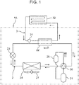
- FIG. 1 is a schematic configuration diagram of a refrigeration cycle apparatus according to a first exemplary embodiment of the present disclosure.
- refrigeration cycle apparatus 1A includes: refrigerant circuit 2 configured to circulate a refrigerant; pump 31 configured to send, to utilization-side heat exchanger 22 of refrigerant circuit 2, water with which the refrigerant exchanges heat at utilization-side heat exchanger 22; and a control device (not shown).
- the refrigerant that circulates through refrigerant circuit 2 is R32 with low global warming potential (GWP).
- GWP global warming potential
- a blowing device such as a fan, is provided instead of pump 31.
- Refrigerant circuit 2 includes compressor 21, utilization-side heat exchanger 22, expansion valve (decompression device) 23, and heat source-side heat exchanger 24 that are annularly connected through pipes.
- Refrigerant circuit 2 of the present exemplary embodiment includes gas-liquid separator (gas-liquid separation device) 25 configured to separate gas and liquid from each other between heat source-side heat exchanger 24 and compressor 21.
- Refrigerant circuit 2 includes four-way valve 26 for shifting between heating operation and defrosting operation.
- refrigeration cycle apparatus 1A serves as a heater of a hot water circulating apparatus configured to perform heating by utilizing hot water generated by the heating operation.
- Utilization-side heat exchanger 22 of refrigerant circuit 2 is configured to heat water by causing the heat exchange between the refrigerant and the water.
- hot water circuit 3 including utilization-side heat exchanger 22 and pump 31 is annularly connected with heating terminal unit 32, such as a radiator or a floor heating panel, and a hot water storage tank (not shown) through pipes, so that hot water circulates through hot water circuit 3.
- heating terminal unit 32 such as a radiator or a floor heating panel
- hot water storage tank (not shown)
- This configuration enables heating terminal unit 32 to perform heating and hot water storage tank (not shown) to supply hot water.
- FIG. 1 Operation of refrigeration cycle apparatus 1A is described below with reference to FIG. 1 .
- the solid arrows indicate the directions in which the refrigerant flows during the heating operation
- the dotted arrows indicate the directions in which the refrigerant flows during the defrosting operation.
- the following passages describe changes in the refrigerant states in the heating operation and the defrosting operation.
- a discharge gas refrigerant that has been compressed by compressor 21 and of which temperature and pressure are increased flows in utilization-side heat exchanger 22 through four-way valve 26. Heat of the refrigerant is released to water that flows in utilization-side heat exchanger 22 from hot water circuit 3. As a result, the refrigerant is condensed to liquid.
- the condensed and liquefied refrigerant is decompressed and expanded by expansion valve 23 and then flows in heat source-side heat exchanger 24.
- the low-pressure two-phase refrigerant that has flown in heat source-side heat exchanger 24 is evaporated by absorbing heat from air blown by fan 27. Then, the low-pressure refrigerant flown out of heat source-side heat exchanger 24 passes through four-way valve 26 and gas-liquid separator 25, and is again drawn into compressor 21.
- a discharge gas refrigerant that has been compressed by compressor 21 and of which temperature and pressure are increased flows in heat source-side heat exchanger 24 through four-way valve 26.
- the refrigerant is condensed to liquid by releasing heat thereof to frost on an outer surface of heat source-side heat exchanger.
- the condensed and liquefied refrigerant is decompressed and expanded by expansion valve 23 and then flows in utilization-side heat exchanger 22.
- the low-pressure two-phase refrigerant that has flown in utilization-side heat exchanger 22 is evaporated by absorbing heat from the water circulating hot water circuit 3. Then, the low-pressure refrigerant flown out of utilization-side heat exchanger 22 passes through four-way valve 26 and gas-liquid separator 25, and is again drawn into compressor 21.
- gas-liquid separator 25 is provided on an inlet side of compressor 21 to prevent a situation in which a large amount of liquid refrigerant directly returns to compressor 21 to cause liquid compression during transient operation of compressor 21, such as startup operation or defrosting operation.
- FIG. 2 is a schematic view of gas-liquid separator 25 provided in refrigerant circuit 2.
- Container 250 includes two pipes, i.e., inlet pipe 251 and outlet pipe 252 each of which provides communication between the interior and exterior of container 250.
- the refrigerant flown from heat source-side heat exchanger 24 enters container 250 of gas-liquid separator 25 through inlet pipe 251, and is divided into liquid refrigerant and gas refrigerant inside container 250 in the case where the inflow refrigerant is in a two-phase state.
- the gas refrigerant thus divided flows in first opening 252a of outlet pipe 252 and returns to compressor 21 through outlet pipe 252.
- the liquid refrigerant thus divided is retained in container 250 of gas-liquid separator 25.
- the level of the divided liquid refrigerant reaches second opening 252b
- the liquid refrigerant flows in outlet pipe 252 through second opening 252b due to the head pressure of the liquid level from second opening 252b and a pressure difference including a pressure drop from first opening 252a to second opening 252b in outlet pipe 252, i.e., a pressure difference between the outlet and inlet of second opening 252b (a pressure difference between the inside and outside of the pipe), and then the liquid refrigerant returns to compressor 21 together with the gas refrigerant.
- the refrigeration cycle apparatus of the present disclosure is configured such that the area of first opening 252a and the area of second opening 252b of gas-liquid separator 25 of refrigeration cycle apparatus 1A using R32 as refrigerant has a ratio of A/B that is equal to or greater than 1.9, when A represents a ratio (b/a) of the area (b) of second opening 252b to the area (a) of first opening 252a, and B represents a ratio (d/c) of the area (d) of second opening 252b to the area (c) of first opening 252a of gas-liquid separator 25 when R410A is used as refrigerant.
- FIG. 3 shows a relationship between a vapor quality of an intake refrigerant of compressor 21 and an outside-air temperature regarding each of the present disclosure using refrigerant R32 and a conventional art using refrigerant R410A under the same conditions of the condensation temperature on a high-pressure side of refrigerant circuit 2 at 56°C, and the discharge refrigerant temperature of the compressor 21 at 100°C.
- FIG. 4 shows a relationship between the vapor quality of the intake refrigerant of compressor 21 and the ratio of A/B in a refrigeration cycle apparatus according to the present disclosure using refrigerant R32, in each of the cases where the liquid level in gas-liquid separator 25 is identical to the liquid level at point "a" of refrigerant R410A in FIG. 3 , where the liquid level in gas-liquid separator 25 is two fifth (2/5) of the liquid level at point "a" of refrigerant R410A in FIG. 3 , and where the liquid level in gas-liquid separator 25 is twice the liquid level at point "a" of refrigerant R410A in FIG. 3 .
- FIGS. 3 and 4 indicate that the refrigeration cycle apparatus of the present disclosure that uses refrigerant R32 can achieve the same condensation temperature on a high-pressure side and the same discharge refrigerant temperature of compressor 21 as in the case in which refrigerant R410A is used, when the ratio A/B is 1.9 and the liquid level in gas-liquid separator 25 is identical to that in the case using refrigerant R410A.
- the refrigeration cycle apparatus of the present disclosure that uses refrigerant R32 can achieve the same condensation temperature on a high-pressure side and the same discharge refrigerant temperature of compressor 21 as in the case in which refrigerant R410A is used, even in the case where the liquid level in gas-liquid separator 25 is two fifth (2/5) the liquid level in the case using refrigerant R410A.
- the discharge refrigerant temperature of compressor 21 of the present disclosure that uses refrigerant R32 is equal to or less than that of the conventional art that uses refrigerant R410A, even in the case where the liquid level in gas-liquid separator 25 is equal to or less than that in the case using refrigerant R410A.
- refrigerant circuit 2 of refrigeration cycle apparatus 1A of the present disclosure is operable while suppressing an abnormal rise in discharge temperature of compressor 21 even in the environment of low outside-air temperatures, such as -20°C, as long as the ratio of A/B that is equal to or greater than 1.9 is satisfied, where A represents a ratio of the area of second opening 252b to the area of first opening 252a of gas-liquid separator 25 using refrigerant R32, and B represents a ratio of the area of second opening 252b to the area of first opening 252a of gas-liquid separator 25 of refrigerant circuit 2 using refrigerant R410A.
- the present disclosure can provide refrigeration cycle apparatus 1A using refrigerant R32 that is capable of suppressing a reduction in operation efficiency and an abnormal rise in discharge temperature without increasing the amount of refrigerant to be charged in refrigerant circuit 2, and is excellent in durability.
- the ratio A/B can be made two or more in the refrigeration cycle apparatus using R32 as refrigerant circulating through refrigerant circuit 2 with a simple measure of enlarging only second opening 252b or decreasing the area of first opening 252a of outlet pipe 252 of existing gas-liquid separator 25 using refrigerant R410A. This eliminates the need for redesign which requires a large numbers of man-hours.
- gas-liquid separator 25 results in the same vapor quality of inlet refrigerant of compressor 21, whereby the outer diameter of container 250 of gas-liquid separator 25 can be reduced. This enables reduction in the amount of usage of materials and the amount of charged refrigerant. As a result, a low-cost and resource-saving refrigeration cycle apparatus can be provided.
- fluid to be heated at utilization-side heat exchanger 22 may be any liquid, and is not necessarily water.
- the present disclosure is especially useful in a liquid circulating apparatus that heats liquid by a refrigeration cycle apparatus and utilizes the liquid to perform heating and to supply hot water.
Landscapes
- Engineering & Computer Science (AREA)
- Physics & Mathematics (AREA)
- Mechanical Engineering (AREA)
- Thermal Sciences (AREA)
- General Engineering & Computer Science (AREA)
- Chemical & Material Sciences (AREA)
- Analytical Chemistry (AREA)
- Power Engineering (AREA)
- Heat-Pump Type And Storage Water Heaters (AREA)
- Compression-Type Refrigeration Machines With Reversible Cycles (AREA)
Applications Claiming Priority (1)
| Application Number | Priority Date | Filing Date | Title |
|---|---|---|---|
| JP2017096426A JP2018194200A (ja) | 2017-05-15 | 2017-05-15 | 冷凍サイクル装置およびそれを備えた液体循環装置 |
Publications (1)
| Publication Number | Publication Date |
|---|---|
| EP3404341A1 true EP3404341A1 (de) | 2018-11-21 |
Family
ID=60953722
Family Applications (1)
| Application Number | Title | Priority Date | Filing Date |
|---|---|---|---|
| EP18150820.1A Withdrawn EP3404341A1 (de) | 2017-05-15 | 2018-01-09 | Kältekreislaufvorrichtung und flüssigkeitsumwälzvorrichtung damit |
Country Status (3)
| Country | Link |
|---|---|
| EP (1) | EP3404341A1 (de) |
| JP (1) | JP2018194200A (de) |
| CN (1) | CN108870788A (de) |
Families Citing this family (1)
| Publication number | Priority date | Publication date | Assignee | Title |
|---|---|---|---|---|
| DE112020001954T5 (de) * | 2019-04-16 | 2021-12-30 | Denso Corporation | Strömungsdurchgangumschaltventil und Fluidzirkulationskreislauf |
Citations (4)
| Publication number | Priority date | Publication date | Assignee | Title |
|---|---|---|---|---|
| EP2728279A1 (de) * | 2012-11-06 | 2014-05-07 | Hitachi Appliances, Inc. | Klimaanlage |
| EP2765370A1 (de) * | 2013-02-08 | 2014-08-13 | Panasonic Corporation | Kühlgerät und Warmwassererzeuger |
| JP2015017720A (ja) * | 2013-07-09 | 2015-01-29 | 日立アプライアンス株式会社 | 空気調和装置 |
| EP2918921A1 (de) * | 2014-03-12 | 2015-09-16 | Panasonic Intellectual Property Management Co., Ltd. | Heisswassererzeuger |
Family Cites Families (4)
| Publication number | Priority date | Publication date | Assignee | Title |
|---|---|---|---|---|
| JP5999274B2 (ja) * | 2013-10-17 | 2016-09-28 | 三菱電機株式会社 | 冷凍サイクル装置 |
| WO2015140885A1 (ja) * | 2014-03-17 | 2015-09-24 | 三菱電機株式会社 | 冷凍サイクル装置 |
| JPWO2015140878A1 (ja) * | 2014-03-17 | 2017-04-06 | 三菱電機株式会社 | アキュムレータ及び冷凍サイクル装置 |
| JP6120797B2 (ja) * | 2014-04-04 | 2017-04-26 | 三菱電機株式会社 | 空気調和機 |
-
2017
- 2017-05-15 JP JP2017096426A patent/JP2018194200A/ja active Pending
-
2018
- 2018-01-09 EP EP18150820.1A patent/EP3404341A1/de not_active Withdrawn
- 2018-03-15 CN CN201810212645.XA patent/CN108870788A/zh active Pending
Patent Citations (5)
| Publication number | Priority date | Publication date | Assignee | Title |
|---|---|---|---|---|
| EP2728279A1 (de) * | 2012-11-06 | 2014-05-07 | Hitachi Appliances, Inc. | Klimaanlage |
| EP2765370A1 (de) * | 2013-02-08 | 2014-08-13 | Panasonic Corporation | Kühlgerät und Warmwassererzeuger |
| JP2014169854A (ja) | 2013-02-08 | 2014-09-18 | Panasonic Corp | 冷凍サイクル装置およびそれを備えた温水生成装置 |
| JP2015017720A (ja) * | 2013-07-09 | 2015-01-29 | 日立アプライアンス株式会社 | 空気調和装置 |
| EP2918921A1 (de) * | 2014-03-12 | 2015-09-16 | Panasonic Intellectual Property Management Co., Ltd. | Heisswassererzeuger |
Also Published As
| Publication number | Publication date |
|---|---|
| CN108870788A (zh) | 2018-11-23 |
| JP2018194200A (ja) | 2018-12-06 |
Similar Documents
| Publication | Publication Date | Title |
|---|---|---|
| JP5847366B1 (ja) | 空気調和装置 | |
| CN100419344C (zh) | 空调装置 | |
| EP3118541B1 (de) | Kältekreislaufvorrichtung | |
| EP3217115B1 (de) | Klimatisierungsvorrichtung | |
| JPWO2012104893A1 (ja) | 空気調和装置 | |
| EP0962725A1 (de) | Klimaanlage die unbrennbares kühlmittel verwendet | |
| JP6479181B2 (ja) | 空気調和装置 | |
| KR101901540B1 (ko) | 공기 조화 장치 | |
| CN105698424A (zh) | 一种超低温制冷的单冷分体式空调器及其超低温制冷方法 | |
| CN107166580A (zh) | 空调供热水系统 | |
| JP6288243B2 (ja) | 空気調和装置 | |
| JP2020094698A (ja) | 冷凍装置 | |
| US20240247845A1 (en) | Heating, ventilation, and air-conditioning systems and methods with bypass line | |
| JP2015218954A (ja) | 冷凍サイクル装置 | |
| EP3404341A1 (de) | Kältekreislaufvorrichtung und flüssigkeitsumwälzvorrichtung damit | |
| JP6238202B2 (ja) | 空気調和機 | |
| JP6343805B2 (ja) | 冷凍装置 | |
| EP3217117A1 (de) | Klimatisierungs-/heisswasserversorgungssystem | |
| KR102636893B1 (ko) | 냉장 시스템 및 방법 | |
| WO2022029845A1 (ja) | 空気調和装置 | |
| JP7535371B2 (ja) | 空気調和装置 | |
| JP2026060406A (ja) | 冷凍サイクル | |
| EP3217118A1 (de) | Wärmepumpenvorrichtung | |
| JP2014031915A (ja) | 冷凍サイクル装置 |
Legal Events
| Date | Code | Title | Description |
|---|---|---|---|
| PUAI | Public reference made under article 153(3) epc to a published international application that has entered the european phase |
Free format text: ORIGINAL CODE: 0009012 |
|
| STAA | Information on the status of an ep patent application or granted ep patent |
Free format text: STATUS: THE APPLICATION HAS BEEN PUBLISHED |
|
| AK | Designated contracting states |
Kind code of ref document: A1 Designated state(s): AL AT BE BG CH CY CZ DE DK EE ES FI FR GB GR HR HU IE IS IT LI LT LU LV MC MK MT NL NO PL PT RO RS SE SI SK SM TR |
|
| AX | Request for extension of the european patent |
Extension state: BA ME |
|
| STAA | Information on the status of an ep patent application or granted ep patent |
Free format text: STATUS: REQUEST FOR EXAMINATION WAS MADE |
|
| 17P | Request for examination filed |
Effective date: 20190521 |
|
| RBV | Designated contracting states (corrected) |
Designated state(s): AL AT BE BG CH CY CZ DE DK EE ES FI FR GB GR HR HU IE IS IT LI LT LU LV MC MK MT NL NO PL PT RO RS SE SI SK SM TR |
|
| STAA | Information on the status of an ep patent application or granted ep patent |
Free format text: STATUS: EXAMINATION IS IN PROGRESS |
|
| 17Q | First examination report despatched |
Effective date: 20210924 |
|
| STAA | Information on the status of an ep patent application or granted ep patent |
Free format text: STATUS: THE APPLICATION IS DEEMED TO BE WITHDRAWN |
|
| 18D | Application deemed to be withdrawn |
Effective date: 20220205 |