EP3404579B1 - Systeme, verfahren und vorrichtungen zur artikelverarbeitung - Google Patents
Systeme, verfahren und vorrichtungen zur artikelverarbeitung Download PDFInfo
- Publication number
- EP3404579B1 EP3404579B1 EP18182067.1A EP18182067A EP3404579B1 EP 3404579 B1 EP3404579 B1 EP 3404579B1 EP 18182067 A EP18182067 A EP 18182067A EP 3404579 B1 EP3404579 B1 EP 3404579B1
- Authority
- EP
- European Patent Office
- Prior art keywords
- item
- information
- pass
- scan data
- label
- Prior art date
- Legal status (The legal status is an assumption and is not a legal conclusion. Google has not performed a legal analysis and makes no representation as to the accuracy of the status listed.)
- Active
Links
Images








Classifications
-
- B—PERFORMING OPERATIONS; TRANSPORTING
- B07—SEPARATING SOLIDS FROM SOLIDS; SORTING
- B07C—POSTAL SORTING; SORTING INDIVIDUAL ARTICLES, OR BULK MATERIAL FIT TO BE SORTED PIECE-MEAL, e.g. BY PICKING
- B07C7/00—Sorting by hand only e.g. of mail
- B07C7/005—Computer assisted manual sorting, e.g. for mail
-
- B—PERFORMING OPERATIONS; TRANSPORTING
- B07—SEPARATING SOLIDS FROM SOLIDS; SORTING
- B07C—POSTAL SORTING; SORTING INDIVIDUAL ARTICLES, OR BULK MATERIAL FIT TO BE SORTED PIECE-MEAL, e.g. BY PICKING
- B07C2301/00—Sorting according to destination
- B07C2301/0058—Verification for the correct postage amount
-
- G—PHYSICS
- G07—CHECKING-DEVICES
- G07B—TICKET-ISSUING APPARATUS; FARE-REGISTERING APPARATUS; FRANKING APPARATUS
- G07B17/00—Franking apparatus
- G07B17/00185—Details internally of apparatus in a franking system, e.g. franking machine at customer or apparatus at post office
- G07B17/00435—Details specific to central, non-customer apparatus, e.g. servers at post office or vendor
- G07B2017/00443—Verification of mailpieces, e.g. by checking databases
Definitions
- the application relates to systems, methods, and devices for item processing. More particularly, the application relates to systems for collecting data, systems for processing data, and methods of using the systems and collected data.
- an item distribution system for item processing comprising a camera suitable for capturing an image of a label located on an item being processed by item processing equipment in the item distribution system, the label including scan data located thereon; a computing system comprising: a memory comprising: a first database suitable for storing scan data comprising an indicator of a label that has already been used in association with at least two different items; and a second database suitable for storing scan data comprising an indicator of a label that has not already been used in association with at least two different items; a processor in communication with the camera and the memory, wherein the processor is configured to: determine if the captured image is acceptable; generate scan data from the captured image of the label; compare information from the scan data to the indicator in the first database to identify a match with the label that has already been used in association with the at least two different items; if a match is identified in the first database, then to cause the item processing equipment to do at least one of redirect the item from a first path toward a first destination to a second
- the camera is configured to capture an image of the item when a label on the item is viewable by the camera within a defined three-dimensional space.
- the processor is further configured to communicate the scan data to a central computing unit comprising a processor and a memory configured to store information and instructions related to the item.
- the processor is further configured to receive instructions relating to the disposition of the item from the central computing unit.
- the system further comprises a cart and a boom, wherein the boom is connected to the cart at a first end and wherein a second end of the boom extends from the cart and the camera is located at the second end of the boom.
- the output comprises at least one of an audible or visual output.
- the visual output comprises a colored light.
- the scan data uniquely identifies the item.
- the label comprises information for determining item processing instructions.
- the item processing instructions identify tasks relating to the item.
- the processor is further configured to: determine a physical characteristic of the item; determine if the information from the scan data corresponds to the physical characteristic of the item; and provide instructions for further processing of the item based on whether the information from the scan data corresponds to the physical characteristic of the item
- the processor is further configured to: identify an indicator of a label that is identified as having been scanned in a designated time frame; determine if information from the scan data corresponds to the indicator of a label that is identified as having been scanned in a designated time frame; and provide instructions for further processing of the item based on whether information from the scan data corresponds to the indicator of a label that is identified as having been scanned in a designated time frame
- a method of item processing in an item distribution system comprising capturing, by an imaging device, an image of a label located on an item being processed by item processing equipment in the item distribution system, the label including scan data located thereon; generating, by a processor of a computing system, scan data from the captured image of the label; comparing information from the scan data to an indicator of a label, in a first database, that has already been used in association with at least two different items, to identify a match; if a match is identified between the label located on the item and the label that has already been used in association with the at least two different items, then causing the computing system to identify the label as fraudulent; if no match is identified in the first database, comparing the information from the scan data to an indicator in a second database to identify a match with a label that has not already been used in association with at least two different items; if a match is identified in the second database, then causing the computing system to identify the label as fraudulent; and if no match is identified
- the method further comprises detecting the presence of an item within a defined three-dimensional image; and triggering capturing the image in response to detecting the presence of the item.
- the method further comprises updating a local database with the scan data.
- the local database is updated with an indicator of the captured image.
- the method further comprises providing information relating to the captured image.
- the information comprises a representation of the captured image.
- the label further comprises information for determining item processing instructions.
- the item processing instructions identify tasks relating to the item.
- the method further comprises : determining a physical characteristic of the item; and determining if the received information associated with the label corresponds to the physical characteristic of the item; and providing instructions for further processing of the item based on whether the information from the scan data corresponds to the physical characteristics of the item.
- the method further comprises: identifying an indicator of a label that is identified as having been scanned in a designated time frame; determining if information from the scan data corresponds to the indicator of a label that is identified as having been scanned in a designated time frame; and providing instructions for further processing of the item based on whether information from the scan data corresponds to the indicator of a label that is identified as having been scanned in a designated time frame.
- Embodiments described and disclosed herein relate generally to systems, methods, and devices for item processing, item scanning, and mailing of one or more items.
- some embodiments relate to systems and devices that can be used to scan an item, and to process an item, to thereby facilitate mailing of one or more items.
- the systems, methods, and devices described herein can provide a number of benefits.
- they can provide benefits relating to the detection of fraud, minimization of payment discrepancies between paid-for services and provided services, employee/productivity management, sorting, routing, the performance of an action on an item and/or the management of tasks relating to an item, sampling of one or several items, altering the provided services for a received item, redirecting an item, and relating to a variety of other areas.
- benefits can be provided, in part, by creating a system to receive and manage information relating to the items.
- the systems, methods, and devices described herein provide for improved item processing.
- Some embodiments relate to a Passive Adaptive Scanning System ("PASS") module.
- the PASS module can include features and modules configured to gather data from an item and to transmit that data to a system.
- the PASS module is further configured to receive instructions from the system and to communicate those instructions to the user of the PASS module.
- the PASS system can include a PASS computing system that can be configured to receive inputs from the PASS module and to provide instructions to the PASS module in response to the received inputs.
- the PASS system can comprise other modules that can communicate with the PASS computing system.
- the PASS computing system collects information from the modules of the PASS system and can use this information to provide instructions and/or information to the PASS module.
- the PASS system can be used to assist in revenue protection, assist in taking action relating to an in-transit item, assist in sorting items into route groups and/or into delivery sequences, assist in collecting, tracking, and completing requested tasks, assist in sampling of items, assist in redirecting enroute items, and assist in employee productivity management.
- the PASS computing system collects information from different modules of the PASS system and adds this information to one or several databases.
- the PASS computing system then, in response to a scanned event by one of the PASS modules, accesses the created database and the information stored therein, and uses that information as it is applicable to the scanned data generated by the PASS module to determine a desired outcome.
- an outcome of the PASS system can be any result from using the PASS system.
- the PASS system can then provide instructions to the PASS module relating to the desired action.
- the PASS module can provide these instructions in multiple formats to a user who can, if necessary, execute these instructions to achieve the desired outcome.
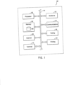
- FIG. 1 depicts one embodiment not claimed of a PASS module 100.
- the PASS module 100 can comprise a variety of features and components, and can be configured to perform a variety of functions. In some embodiments not claimed, for example, the features and components of the PASS module 100 can be physically connected and/or in communication with each other. Thus, in some embodiments not claimed, the components of the PASS module 100 are in a single location and in other embodiments not claimed, the components of the PASS module 100 can be in multiple locations. In some embodiments not claimed in which the components of the PASS module are in different locations, these components can be in communication with each other.
- the PASS module 100 can, in some embodiments not claimed, be configured to collect information from an item, this can be accomplished, for example, by scanning the item.
- the item can be, for example, a package, a letter, or any other identifiable object.
- the PASS module 100 can be further configured to receive inputs from a user.
- the PASS module 100 can communicate the information collected from the item and/or the inputs received from the user to other systems, and/or components of other systems.
- the PASS module 100 can be further configured to receive information, instructions, and/or other communications from the systems and/or modules of other systems, some of which will be disclosed below.
- the PASS module 100 can be configured to, in response to these received communications, provide outputs to the user.
- the components and modules of the PASS module 100 can be in communication via a communication feature 101.
- the communication feature 101 can comprise any feature capable of establishing a communicating connection between the features and modules of the PASS module 100 and can include, for example, a wired or wireless device, a bus, a communications network, or any other suitable communication feature.
- the PASS module 100 can further comprise a processor 102.
- the processor 102 may comprise a single processor, or may be a component of a processing system implemented with one or more processors.
- the one or more processors 102 may be implemented with any combination of general purpose microprocessors, microcontrollers, digital signal processors (DSPs), field programmable gate array (FPGAs), programmable logic devices (PLDs), controllers, state machines, gated logic, discreet hardware components, dedicated hardware, finite state machines, or any other suitable entities that can perform calculations or other manipulations of information.
- DSPs digital signal processors
- FPGAs field programmable gate array
- PLDs programmable logic devices
- the processor 102 can be configured to receive inputs and signals from other components and/or modules of the PASS module 100.
- the processor can be further configured to perform operations with the inputs received from other components and/or modules of the PASS module 100.
- the processor 102 can execute stored instructions, and can direct the operation of the other components and/or modules of the PASS system 100.
- the processor 102 can communicate with other components and/or modules of the PASS module 100 via the communication feature 101.
- the processor 102 can send signals to and receive signals from other components and/or modules of the PASS module 100 via the communication feature 101.
- the PASS module 100 can comprise a memory 104.
- the memory 104 can be physically located at and/or in the PASS module 100, and in some embodiments not claimed, the memory 104 can be located remote from the PASS module 100.
- the memory 104 can include, for example, RAM memory, flash memory, ROM memory, EPROM memory, EEPROM memory, registers, hard disk, a removable disk, a CD-ROM, or any other form of storage medium known in the art.
- the memory can include, for example, software, at least one software module, instructions, steps of an algorithm, or any other information.
- the processor 102 can perform processes in accordance with instructions stored in the memory 104.
- These processes can include, for example, controlling features and/or components of the PASS module 100, requesting and/or receiving information from features and/or components of the PASS module 100 and/or the features and/or components of other systems and/or modules or components of other systems, transmitting instructions and/or control signals to other systems and/or features and/or components of the other systems, requesting information from the user, transmitting information to the user, processing information received from features and/or components of the PASS module 100, and/or from features and/or components of other connected systems, processing information received from the user, and/or any other desired processes.
- the memory 104 can comprise one or several databases.
- the databases can comprise an organized collection of digital data.
- the data stored in the databases can comprise any desired data, and can, in some embodiments not claimed, relate to functions of the PASS module 100 and/or any other connected or related systems.
- the memory 104 can comprise a database 106.
- the database 106 can be a scanned database.
- the scanned database can comprise information collected by the PASS module 100. This information can include, for example, scanned images generated by the PASS module 100 and/or any other data affected by the PASS module 100.
- the scanned database can collect scanned images and/or other data collected by the PASS module 100 for a designated period of time. In some embodiments not claimed, the duration of the designated period of time can be limited by the amount of available memory, and by the usefulness of aged data.
- the scanned database can comprise information relating to all of the scans collected in, for example, the past six months, or any other desired timeframe.
- the database 106 can comprise an input database.
- the input database can comprise information relating to one or more user inputs.
- these user inputs can relate to an item such as, for example, the physical properties of the item.
- the user may input these physical parameters into the PASS module 100. These input physical parameters can then be stored in the input database.
- the database 106 can comprise a user database.
- the user database can comprise information relating to users of the PASS module 100. This information can include, for example, times during which the user used the PASS module, number of items processed by a user, or any other user-related information.
- the database 106 can, for example, comprise any other desired information, and is not limited to the above listed specific database embodiments.
- the memory 104 can communicate with the communication feature 101 of the PASS module 100.
- the processor 102 is in communicating connection with the memory 104, and can query the memory 104 for instructions and information.
- the processor 102 can communicate information to the memory 104 and for storage in the memory.
- the PASS module 100 can comprise, as depicted in Figure 1 , a scanner module 108.
- the scanner module 108 can be configured to collect information from an item.
- the scanner module 108 can be configured to read text and/or text strings located on the item, computer-readable code located on the item such as, for example, a barcode including a linear bar code, a 2D barcode, a QR code, an intelligent mail barcode, and/or any other desired computer-readable code, and/or collect any other desired format of information on the item.
- the scanner module 108 can be configured to generate image data of the item.
- the scanner module 108 can generate and/or collect one or several still images of the item and/or one or several films of the item.
- the scanner module 108 can be configured to have sufficient resolution so as to allow use of the collected image data to generate scan data relating to information on the item.
- the scanner module 108 can include features configured to achieve the desired resolution of the images.
- the scanner module can comprise one or several lights. In some embodiments not claimed these lights can be configured to illuminate the item of which image data is being generated. In some embodiments not claimed for example, these lights can be configured to achieve a minimum level of lighting of the item. In some embodiments not claimed for example, these lights can be configured to achieve a minimum level of lighting of a certain and/or specific frequency. In some embodiments not claimed for example, these lights can comprise one or several light bulbs, one or several LEDs, and/or one or several of any other light-generating feature.
- the scanner module 108 can comprise features configured to facilitate use of the scanner module 108. In some embodiments not claimed these features can be configured to facilitate the generation of accurate scan data, and/or the collection of the desired image data. In some embodiments not claimed for example, these features can include targeting features configured to assist the user in aligning the item with the viewing area of the scanner module 108, in other words, the area viewed by the scanner module 108. In some embodiments not claimed for example, these targeting features can define the boundaries of the area for which the scanner module 108 generates image data. In some embodimcnts not claimed these targeting features can indicate the center of the area for which the scanner module 108 generates image data.
- these targeting features can comprise a crosshair, a grid, an "X", and/or any other desired feature configured to facilitate targeting.
- the targeting feature can comprise a projected crosshair and/or projected grid.
- this projected crosshair and/or projected grid can be projected onto an item placed in the viewing area, and can thus be viewable on an item placed in the viewing area to thereby allow the proper positioning of the item.
- this targeting feature can indicate a target zone, or a horizontal area normal to the direction in which the scanner module 108 is pointed.
- the target zone can be associated with a target area.
- the target area comprises the range of distances from the scanner module 108 in which the item can be placed and a successful image data can be generated from the item.
- the target zone and target area define a third area in which successful image data can be generated.
- the scanner module 108 can be, for example, controlled by a processor. In some embodiments not claimed the processor controlling the scanner module 108 can comprise the processor 102. In some embodiments not claimed for example, the processor controlling the scanner module 108 can comprise a different processor than the processor 102 discussed above. In some embodiments not claimed the scanner processor can be in communication with a scanning memory separate from memory 104, and can operate in accordance with instructions stored in the scanning memory.
- the instructions stored in the scanning memory can include, for example, instructions to determine when an item is in the target zone and in the target area, instructions to determine when a desired portion of the item such as, for example, a specified label type or one of several label types, is within a certain region of the target zone and/or target area.
- these instructions can include directing the scanner 108 to capture images when the item is detected in the target zone and/or target area and when the desired portion of the item, such as the label and/or several labels, is within the certain specified region of the target zone and/or target area.
- the scanner module 108 can be housed in a single housing, and in other embodiments not claimed the scanner module 108 can be divided up into multiple separate housings.
- dividing the scanner module 108 into separate housings can facilitate using the scanner module 108 in certain applications.
- the PASS module 100 can include a terminal 110, as depicted in Figure 1 .
- the terminal can be configured to allow a user to interact with the PASS module 100.
- the terminal 110 can provide outputs to the user and/or receive inputs from the user.
- the terminal 110 can be in communicating connection with the other components and/or modules of the PASS module 100 via the communication feature 101.
- the terminal 110 can send information and/or signals to and receive information and/or signals from the other components and/or modules of the PASS module 100.
- the terminal 110 can comprise a variety of features and/or components. In some embodiments not claimed the terminal 110 can comprise any device and/or system capable of providing outputs to a user and receiving inputs from a user. In some embodiments not claimed the terminal 110 can include features to facilitate the providing of outputs to the user and receiving inputs from a user including, for example, a screen, a keypad, a touch screen, a speaker and a microphone, and/or any other features capable of providing output to a user and receiving inputs from a user.
- the terminal 110 can include a processor and memory separate from the processor 102 and memory 104 of the PASS module 100, and in some embodiments not claimed the terminal 110 can use the processor 102 and memory 104 of the PASS module 100.
- the PASS module 100 can further include a guidance module 112.
- the guidance module 112 can be configured to provide simple outputs to direct the actions of the user.
- these outputs can comprise audio and/or visual information indicating a desired action.
- these audio and/or visual outputs can indicate the success of a scan operation, how to sort an item, for the user to use the terminal 110 to provide further information relating to the item, for the user to perform an action relating to the item, and/or any other desired instruction.
- the guidance module 112 can comprise one or several components capable of providing these instructions and/or outputs to instruct the user.
- the guidance module 112 can include, for example, an indicator of scan success.
- this indicator of scan success can comprise one or several lights located in the scanner module 108.
- these lights located in the scanner module 108 can be configured to project colored light onto the item after the scanning operation.
- the color of light projected onto the item after the scanning action can vary based on whether the scanning operation was successful.
- a green light can be projected onto the item after a successful scanning operation
- a red light can be projected onto the item after an unsuccessful scanning operation.
- the guidance module 112 can comprise an audible indicator of scanning success. In some embodiments not claimed this can include a speaker located on the PASS module 100 that provides audible signals indicating whether a scanning operation was successful. In some embodiments not claimed these audible signals can be distinguishable to allow a user to determine whether a scan operation was successful.
- the guidance module 112 can comprise features and/or components configured to indicate an action that the user should take.
- these actions can include, for example, placing the item in a pre-designated area, removing the item from circulation, ascertaining the physical properties of the item, sampling the item, seizing the item, verifying payment information of the item, and/or any other desired action.
- these features can include, for example, lights such as the lighting of an area in which an item should be placed, a display capable of indicating a next action and/or displaying text and/or text strings, speakers configured to provide audible indications of a next action, and/or any other desired feature.
- the PASS module 100 can, in some embodiments not claimed comprise a communications module 114.
- the communications module 114 can be in communication with the communications feature 101 and thereby in communicating connection with all of the other features and/or components of the PASS module 100.
- the communications module 114 can be configured to communicate with other PASS modules 100 and/or other systems and/or components of other systems.
- the communications module 114 can be configured for wired and/or wireless communication, and can be configured to request information and receive inputs from other systems and/or other components of other systems.
- the communications module 114 can receive instructions from the processor 102 directing the operation of the communications module 114. In some embodiments not claimed for example, these instructions from the processor 102 can be in accordance with stored instructions found in the memory 104.
- the PASS module 100 can further comprise a testing module 116.
- the testing module 116 can be configured to facilitate ascertaining information related to a scanned item.
- this information related to a scanned item can comprise, for example, physical information relating to the scanned item such as the dimensions of the scanned item, the weight of the scanned item, the type of services requested for the scanned item, the nature and/or contents of the scanned item, and/or any other desired physical information relating to the scanned item.
- the testing module 116 can include features and components to facilitate the gathering of information relating to the scanned item. In some embodiments not claimed these features and/or components can include sensors capable of detecting the desired physical properties relating to the scanned item. Thus, in some embodiments not claimed the testing module 116 can comprise, for example, a scale, and/or sensors capable of determining the other parameters of the scanned item. In some embodiments not claimed the testing module 116 can include items configured to assist in determining the dimensions of a scanned item such as, for example, a measuring tape, a measuring stick and/or yardstick or ruler, and/or any other user-operated measuring device. In some embodiments in which the user uses a measuring device to determine the dimensions of the scanned item, the user can use the terminal 110 to provide inputs to the PASS module 100 relating to the dimensions of the scanned item.
- the testing module 116 can comprise further sensors and/or components to ascertain other information relating to the scanned item.
- sensors and/or components can include, for example, metal detectors, x-ray machines, sensors configured to detect explosives, sensors configured to detect drugs and/or other illegal contraband such as, for example, prohibited food products, prohibited chemicals, prohibited liquids, and/or any other prohibited item.
- the testing module 116 can cooperate with the processor 102 to verify the correctness and/or compliance of a tested item.
- the testing module 116 can provide information related to the scanned item to the processor 102.
- the processor 102 can compare this information from the testing module 116 with information contained in the item label to verify the correctness of the item label information.
- some embodiments of the PASS module 100 can include a printing module 100.
- the printing module 118 can be configured to create labeling for applying to the item.
- this labeling can be updated destination labeling, updated labeling requesting services related to the scanned item, updated labeling relating to the cost of the services provided for the scanned item, and/or any other desired additional labeling.
- the printing module 118 can communicate with the communications feature 101 and thereby communicate with the other components and/or modules of the PASS module 100.
- the printing module 118 can provide information to the processor 102 and receive instructions from the processor 102.
- the printing module 118 can comprise one or more printers that can be configured to print the additional labeling for applying to the item.
- a PASS module 100 can comprise more or fewer components and/or modules than those outlined herein and that a PASS module 100 can perform more or fewer functions than those outlined herein.
- FIG. 1 depicts one embodiment of physical features associated with a PASS module 100 to facilitate the use of the PASS module 100.
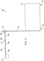
- Figure 2 is a side view depicting a PASS cart 200.
- a PASS cart can be configured to hold all the components of the PASS module 100.
- the PASS cart 200 can be configured to be mobile.
- the PASS cart 200 can be configured to be fixed in one position.
- the PASS cart 200 can comprise a variety of shapes and sizes and can have a variety of features and dimensions.
- the PASS cart 200 depicted in Figure 2 comprises a body 202 that can comprise a variety of shapes and sizes and features.
- the body 202 can be configured to hold and/or support the components and/or modules of the PASS module 100.
- the body 202 can include shelves, cabinets, drawers, and other storage features to facilitate in storing the modules and/or components of the PASS module 100.
- the body 202 can be sized and dimensioned to allow it to withstand the demands of holding the PASS module components.
- the body 202 can be configured to resist tipping when it is loaded with the modules of the PASS module 100.
- the body 202 can be connected to wheels 204.
- the PASS cart 200 can comprise a vertical track 206.
- the vertical track 206 can be connected at a first end to the body 202 of the PASS cart 200.
- the second end of the vertical track 206 can extend vertically above the body 202 of the PASS cart 200.
- the vertical track 206 can be configured to allow for vertical positioning of sliding member 207 along the vertical track 206.
- the sliding member 207 may be positioned in close proximity to the wheel 204 of the body 202, and in some embodiments not claimed the sliding member 207 may be positioned proximate to the second end of the vertical track 206.
- the vertical track 206 and the sliding member 207 can be configured to withstand loads associated with an arm 208 connected at a first end to the sliding member 207 and connected at a second end to a camera 210.
- the size, dimensions, and materials of both vertical track 206 and the sliding member 207 can vary based on the properties of the arm 208 and the camera 210, such as, for example, the weight of the arm 208 and the camera 210, the length of the arm 208, and the range of positions relative to the vertical track 206 in which the arm 208 can be positioned.
- Figure 2 depicts one embodiment of an arm 208 included in the PASS cart.
- the arm 208 comprises a plurality of rigid members 208a connected by a plurality of joints 208b.
- the joints 208b can be configured to allow the angular displacement of the rigid members 208a relative to each other. In some embodiments not claimed this displacement can be limited to a plane that is perpendicular to the longitudinal axis of the vertical track 206, and can comprise, a horizontal plane.
- the configuration of the arm 208 with rigid members 208a joined by joints 208b allows the arm 208 to articulate and be moved through a variety of positions and distances from the vertical track 206.
- the joints 208b of the arm 208 are configured to allow movement in a horizontal plane, which plane is perpendicular to the longitudinal axis of movement of the vertical track 206.
- the combination of vertical track 206 and the articulating ability of the arm 208 via the joints 208b can allow positioning of the camera 210, which is affixed at the second end of the arm 208, by, for example, one or several bolts, in a variety of vertical as well as horizontal positions.
- the camera 210 can be located at the second end of the arm 208.
- the camera can be a component of the scanner module 108.
- the camera 210 can be a digital camera, a scanner, a barcode reader, or any other device capable of retrieving information from an item.
- the camera 210 can comprise a high-resolution, high-speed camera 210 capable of retrieving a variety of information types from an item including, for example, information in computer-readable codes such as, for example, barcodes, information contained in text and/or text strings such as, for example, a written name and or written address, information contained in the signaling device such as, for example, an RFID tag, or any other desired type of information.
- the camera 210 can be configured to minimize its weight to thereby minimize the moment applied to the arm 208, to the vertical track 206, to the sliding member 207, and to the body 202. In some embodiments not claimed these weight minimizations can be achieved by dividing the camera 210 into an optical component located at the second end of the arm 208 and a processing component located in or on the body 202. In some embodiments not claimed the optical component of the camera 210 and the processing component of the camera 210 can be in communication with each other to transmit information collected by the optical component to the processing component of the camera 210.
- the body 202 can include features to increase its weight, to lower its center of gravity, and to prevent instability in the body 202 and the tipping of the body. In some embodiments not claimed these features can include, for example, a steel plate located at the bottom of the body 202.
- PASS cart 200 can comprise more or fewer features than those outlined and discussed herein.
- the PASS cart 200 can be used with other features and components to facilitate performing an operation on an item and/or in processing an item.
- Figure 2A depicts one embodiment of a PASS cart 200 in use with other components to facilitate item processing.
- Figure 2A depicts one embodiment of a bullpen 220.
- a bullpen 220 can comprise, for example, a PASS cart 200 having a body 202, an arm 208, and a camera 210 located at the second end of the arm 208.
- the PASS cart 200 can be used to collect information from an item, to assist in performing an action on an item, and/or to provide instructions as to an action to be taken in regards to an item.
- the PASS cart 200 can provide instructions to place the item for which information has been collected by the PASS cart 200 in a receptacle 222.
- a plurality of receptacles 222 can be arranged around a PASS cart 200.
- each of these receptacles 222 can correspond to a different action, outcome, and/or instruction indicated by the PASS cart 200.
- the PASS cart 200 will provide an indication that an item, for which information has been collected by the PASS cart 200, should be placed in a specified one of the receptacles 220, and the PASS cart 200 can provide instructions that another item should be placed in a different specified receptacle 222.
- these different receptacles 222 can correspond to different sortations of the items, to different actions to be performed on the items, to different types of items, and/or any other desired sortation, outcome, and/or action.
- the receptacles 222 can comprise a variety of items and can comprise a variety of shapes and sizes. In some embodiments not claimed a receptacle 222 can be any feature and/or thing capable of receiving an item. Thus, a receptacle 222 could be a designated area, a box, a hamper, a pallet, a crate, a conveyor belt, and/or any other designated device, feature or location.
- the receptacle 222 can comprise features configured to assist the user in placing the item in the proper receptacle 222. In some embodiments not claimed for example, these features can include an indicator that provides an audio and/or visual signal indicating in which of the receptacles 222 an item should be placed. In some embodiments not claimed this feature and/or component of the receptacle 222 is in communication with the PASS module 100. Thus, in some embodiments not claimed this feature of the receptacle 222 can be triggered by the PASS module 100 in response to determining a receptacle 222 for receiving the item.
- Figure 2A also shows a source 224.
- the source 224 can comprise any feature capable of bringing items to the bullpen 220.
- the source 224 can comprise a hamper, a pallet, a conveyor, a cart, a wagon, and/or any other similar feature or device.
- Figure 2A depicts one layout of a bullpen 220 in which the PASS cart 200 is located in the center of a U-shaped arrangement of a plurality of receptacles 222.
- such an arrangement allows easy access to the PASS cart 200 as well as to each of the receptacles 222.
- a person of skill in the art will recognize, however, that more or fewer receptacles 222 could be used in a bullpen 220, and that more or fewer sources 224 and PASS carts 200 could be used in a bullpen.
- a person of skill in the art will further recognize that the present disclosure is not limited to this specific embodiment of a bullpen 220, but rather covers the concept of using a bullpen 220 in connection with a PASS cart 200.
- the PASS module 100 can be embodied in one or several handheld devices.
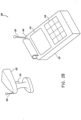
- Figure 2B depicts one such embodiment in which the PASS module 100 is embodied in a handheld PASS unit 240.
- the handheld PASS unit 240 can comprise all or some of the modules and components of the PASS module 100.
- the handheld PASS unit 240 can comprise a hand device 242.
- the hand device 242 can be configured to be held in the hand of a user.
- the hand device 242 can be configured to collect scan data, to store and/or process scan data, and to transmit the scan data to other systems and/or components of other systems.
- the hand device 242 can comprise a screen 244 and a keyboard 246.
- the screen 244 can be configured to provide outputs to the user such as, for example, instructions and/or prompts
- the keyboard 246 can be configured to allow a user to provide inputs to the hand device 242.
- the hand device 242 depicted in Figure 2B includes a screen 244 and a keyboard 246, the hand device 242 can comprise any number of features configured to provide outputs to a user and to receive inputs from a user, including, for example, a speaker and a microphone.
- the hand device 242 includes a printer 248.
- the printer 248 can correspond to the printing module 118 of the PASS module 100, and can be configured to print labels for applying to an item.
- the hand device 242 can include an antenna 250. In some embodiments not claimed the antenna can be configured to communicate with other devices of the handheld PASS unit 240, and/or to communicate with other systems and/or components and modules of other systems.
- the handheld PASS unit 240 can further include a scanner 252.
- the scanner 252 can correspond to the scanner module 108 of the PASS module 100.
- the scanner 252 can comprise a camera, a barcode reader, and/or any other device capable of gathering information from the item.
- the scanner 252 can be configured with a trigger 254.
- the depressing of the trigger 254 can activate the scanner 252 to collect and generate scanned data from the item.
- the scanner 252 can further comprise an antenna 256.
- the antenna 256 of the scanner 252 can be configured to allow communication between the scanner 252 and the hand device 242.
- the antenna 256 of the scanner 252 can be used to transmit scanned data from the scanner 252 to the hand device 242.
- the handheld PASS unit 240 can include features corresponding to the some or all of the features and or modules of the PASS module 100
- the handheld PASS unit 240 can comprise more or fewer components and modules than those listed herein, and that the present disclosure of the handheld PASS unit 240 is not limited to the specific embodiment disclosed herein.
- the PASS system 300 can be configured to perform item processing functions relating to, for example, revenue protection, the requesting of actions relating to an item, sorting functions including sorting into routes and/or into delivery sequences, task management relating to items, random sampling and/or sampling of items, change of addressing for items, employee management relating to item processing, and item redirect.
- item processing functions relating to, for example, revenue protection, the requesting of actions relating to an item, sorting functions including sorting into routes and/or into delivery sequences, task management relating to items, random sampling and/or sampling of items, change of addressing for items, employee management relating to item processing, and item redirect.
- the PASS system 300 can comprise a variety of components, modules, and systems. In some embodiments according to the claims, the PASS system 300 can be located in a single location, and in some embodiments according to the claims, all of the modules and components and features of the PASS system 300 can be located in a single place. In other embodiments according to the claims, the modules, components, and other features of the PASS system 300 can be located in different locations and can be in communicating connection with each other.
- the PASS system 300 can comprise a wide range of features and components, and is not limited to any specific components and/or modules or any specific functions.
- the PASS system 300 can comprise a PASS computing system 301.
- the PASS computing system 301 can be configured to receive inputs, such as information, from the other modules and/or components of the PASS system, to process these inputs, to store these inputs, and to provide instructions to the other modules and/or components of the PASS system 300.
- the PASS computing system can comprise, for example, a central computing unit 302 connected to a memory 304.
- the central computing unit 302 can be configured to receive inputs from the other components and/or modules of the PASS system 300 and provide instructions to the other components and/or modules of the PASS system 300.
- the central computing unit 302 can comprise one or more processors, one or more computers, and/or any other feature or component capable of performing processing operations.
- the central computing unit is a supercomputer as disclosed in U.S. Patent Application No. 13/083,396 filed on April 8, 2011 , the entirety of which is incorporated by reference herein.
- the central computing unit 302 of the PASS computing system 301 can be in communicating connection with a memory 304.
- the memory 304 can comprise a variety of information including, for example, stored instructions to direct the operation of the central computing unit 302 and the operation of the PASS system 300.
- the memory 304 can be physically located at and/or in the PASS computing system 301, and in some embodiments according to the claims, the memory can be located remote from the PASS computing system 301.
- the memory 304 can include, for example, RAM memory, flash memory, ROM memory, EPROM memory, EEPROM memory, registers, hard disk, a removable disk, a CD-ROM, or any other form of storage medium known in the art.
- the memory can include, for example, software, at least one software module, instructions, steps of an algorithm, or any other information.
- the central computing unit 302 can perform processes in accordance with instruction stored in the memory 304.
- These processes can include, for example, controlling features and/or components of the PASS computing system 301, requesting and/or receiving information from features and/or components of the PASS system 300, transmitting instructions and/or control signals to features and/or components of the PASS system 300, requesting information from an administrator, transmitting information to the administrator, processing information received from features and/or components of the PASS system 300, processing information received from the administrator, and/or any other desired processes.
- the memory 304 can comprise one or several databases.
- Figure 3 depicts one embodiment of a PASS system 300 in which the memory 304 comprises a first database 306 and a second database 308.
- the databases in the memory 304 can relate to the different modules of the PASS system 300.
- the databases can include information relating to the functional state of the components and/or features of the other modules, service requests by the other features and/or modules.
- the databases found in the memory 304 can, for example, include information relating to the users of the PASS system 300. In some embodiments according to the claims, this information can include information relating to a user's or a group of users' output and/or work product, to the amount of time that these users have spent using the PASS system 300, and/or any other work- and or efficiency-related parameter.
- the databases found in the memory 304 can include, for example, scan data.
- this scan data can be used to detect if a label has been used multiple times for different items.
- this scan data can be used to determine if the amount paid for a service matches the actual cost of providing the service and/or the actual cost for receiving the service.
- the memory 304 in which the memory 304 comprises one or more databases including scan data, can comprise a first database 306 that is a match database.
- the match database can include information relating to labels that have already been used in association with at least two items.
- the match database can include information relating to labels that have been used multiple times during some time period such as, for example, in the past six years.
- scan data stored in the match database can be the entire scan data, or it can be a compressed portion of the scan data such as, for example, a hash generated from the scan data that uniquely identifies the scan data.
- a second database 308 can comprise a scan database.
- the scan database can comprise the scan data for all scans in a certain period of time.
- the scan database can comprise the complete scan data for all the scans taken in, for example, the past six months.
- the scan database can comprise the scan data for all scans taken in the past six months that have not been identified as already being used multiple times. In the event that a label is used multiple times, its scan data can be transferred from the scan database to the match database.
- the memory can comprise an action database.
- An action database can comprise a list of requested actions to be performed on an item.
- these actions can include redirecting an item from one destination point to a new destination point, removing an item from circulation, testing and/or sampling an item, seizing an item, evaluating the contents of an item and/or the physical characteristics of an item, and/or performing an investigation relating to the item.
- the memory 304 can comprise a route database.
- the route database can include information dividing a geographic area into routes. In some embodiments according to the claims, these routes can be static and thus remain constant. In some embodiments according to the claims, these routes can be dynamic and the route information stored in the database can comprise a function that varies the route based on variables such as the day of the week, the amount of items to be delivered, and/or any other variables. Thus, in some embodiments according to the claims in which the route information in the database is dynamic, the designated route may change based on the day of the week that an item is delivered and the number of items that should be delivered that day.
- the memory 304 includes an address database.
- the address database can include a list of recipients who have indicated that their address has changed or will be changing.
- the address database can include a list of old addresses of recipients who address is changing and/or has changed and a list of the new addresses for recipients whose address is changing and/or has changed.
- the address database can further include date information indicating when the address change is to take place, the duration of time for which items addressed to the old address should be forwarded to the new address, and any other information, such as delivery preferences.
- the memory 304 can comprise a sortation database including information relating to how the scanned items should be sorted.
- the memory 304 can comprise any number of databases and that the memory 304 is not limited to the specific databases outlined herein.
- the PASS system 300 can, as depicted in Figure 3 , include a communications network 309.
- the communications network 309 can comprise any feature and/or communications system to allow the different features and/or modules of the PASS system 300 to communicate with each other.
- the communications network 309 can comprise a wireless communications network, a wired communications network, and/or any other communications network.
- the communications network 309 can allow communications via existing networks such as a cellular network, a local area network, a wide area network, a telephone network, and/or any other existing communications network.
- some embodiments of the PASS system 300 can include one or more PASS modules 100.
- the PASS module 100 can be configured to generate scan data and provide that scan data to another system and/or modules and components of another system.
- the PASS module 100 can be further configured to receive instructions and/or outputs from another system and/or other components of another system.
- the PASS module 100 can be configured to communicate with the central computing unit 302 and provide scan data and other information relating to the item to the central computing unit 302 and to receive instructions and/or other information from the central computing unit 302.
- the PASS system 300 can further include, for example, a processing module 310.
- the processing module 310 includes all equipment and/or components other than PASS modules 100 involved in the processing of items. These can include, for example, scanners, sorters, and/or any other similar equipment.
- features and/or components of the processing module 310 are configured to scan items, to determine one or several properties of items, to sort items, and/or to dispose of items.
- the processing module 310 is in communicating connection with the central computing unit 302.
- the processing module 310 can provide information relating to items that have passed through the processing module 310 to the central computing unit 302.
- the processing module 310 can receive instructions from the central computing unit 302 relating to items passing through the processing module 310.
- the PASS system 300 can further include an administration module 312.
- the administration module 312 can be configured to monitor the operations of the PASS system 300, to monitor employee and/or user efforts relating to the PASS system 300, to provide inputs to the PASS system 300 to direct the operation of the PASS system 300, and/or any other desired functions.
- the administration module 312 can comprise one or several computing devices and/or one or several terminals.
- the administration module 312 can be configured to allow an administrator to provide inputs to the PASS system 300 and to receive outputs from the PASS system 300.
- these inputs relate to the directing of the efforts of the PASS system 300 and the directing of the operation of the PASS system 300.
- these outputs can relate to the functioning of the PASS system 300, data generated by the PASS system, and/or any other desired output.
- the administration module 312 can communicate with the other modules of the PASS system 300, and in particular communicate with the central computing unit 302 via the communications network 309. Thus, the administration module 312 can provide inputs to the central computing unit 302 and receive outputs from the central computing unit 302.
- the PASS system 300 can include a security module 314.
- the security module can be configured to allow a user and/or security administrator to provide security-related input to the PASS system 300 and to receive security-related outputs from the PASS system 300.
- the security module 314 can comprise a terminal, a computing device, and/or any other hardware or software capable of providing inputs to the PASS system 300 and receiving outputs from the PASS system 300.
- the security-related inputs can relate to fraudulent activities such as, for example, account fraud including unapproved use of a user account, label fraud including use of duplicate, invalid, and/or improper labeling, and payment fraud including, credit card theft, I.D. theft, and the like.
- the security-related inputs can related to criminal activities such as, for example, an item containing illegal contents, an item sent with criminal intent such as, for example, a destructive device, and/or any other criminal-related content.
- the security-related input can further include a requested action related to the designated item, and an association between the requested action and a specified item.
- the security-related input can identify an item and identify an action to be taken in regards to that item.
- the security-related inputs can be provided by a third party, such as, an investigative and/or police service, by a bank, and/or any other security related third party.
- the security-related outputs can include, for example, the present location of an item, the location of the item at which point the requested action was taken, the resolution of the security concern and/or of the action, and whether the requested action is allowed.
- the security module 314 can communicate via the communications network 309 with the other components of the PASS system 300 including, for example, the central computing unit 302.
- the security module 314 can provide inputs to the central computing unit 302 and receive outputs from the central computing unit 302.
- some embodiments of the PASS system 300 can comprise, for example, a payment module 316.
- the payment module 316 can be configured to provide payment-related inputs and receive payment-related outputs.
- a payment module 316 can be configured to track information relating to a group of items and to determine cost of shipping or providing services to that group of items.
- the payment module 316 can, in connection with the other components and/or modules of the PASS system 300, indicate the labels for which a cost of providing services needs to be determined, and receive information relating to the determined cost of the services provided for those items. As depicted in Figure 3 , the payment module 316 can be in communicating connection with the other modules of the PASS system 300 via the communications network 309.
- the PASS system 300 can further include a verification module.
- the verification module 318 can be configured to review information relating to potential duplicate labels and/or other potential fraudulent activities to determine whether or not a duplicate label has been created and/or whether a fraudulent activity has been perpetrated.
- the verification module can comprise a variety of hardware and/or software capable of receiving the various inputs relating to a potential duplicate label and/or potential fraudulent activity and compare this information to determine whether or not a duplicate label has been used and/or whether a fraudulent activity has been perpetrated.
- the verification module can comprise one or more workstations and one or more users.
- the information can be displayed on a monitor at a work station to a user.
- the user can then, based on the information displayed on the monitor, determine whether or not a duplicate label has been used and/or whether a fraud has been perpetrated.
- the user can then provide an indication as to whether the label is a duplicate and/or whether a fraud has been perpetrated, which information can be communicated from the verification module 318 to the other modules of the PASS system 300 via the communications network 309.
- the PASS system 300 can comprise more or fewer modules than those depicted in Figure 3 .
- the PASS module can comprise and perform more or fewer functions than those described specifically above in relation to Figure 3 .
- the modules and/or components of the PASS system 300 can be replicated so as to have any number of any of the above-specified modules such as, for example, one PASS module 100, two PASS modules 100, and/or any other number of PASS modules 100.
- the PASS module 100 can be used in connection with other components of the PASS system 300 for item processing.
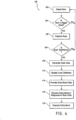
- Figure 4 is a flowchart illustrating one embodiment of a method 400 for using the PASS module 100.
- the process begins at block 402 when the scanner module 108 detects an item.
- the scanner module 108 can detect an item by identifying qualifying labels and/or other features on the item.
- a processor located within the scanner module 108 can detect the item, and in other embodiments the processor 102 can receive signals from the scanner module 108 and the processor 102 can detect the item.
- the process 400 proceeds to decision state 404 and the PASS module 100 determines if the item is in the trigger zone. In some embodiments not claimed for example, this determination can be made by the processor 102 and in some embodiments in which the scanner module 108 comprises a processor, this determination can be made by the scanner module 108. In some embodiments not claimed for example, this determination can be made by determining whether a designated portion of the item such as one or several of the labels is located within a specified portion of the trigger zone. If the PASS module 100 determines that the item is not in the trigger zone, then the process returns to block 402 and waits for detection of an item.
- the process 400 moves to block 406 and the PASS module 100 captures a scan of the item.
- the scanner module 108 of the PASS module 100 can capture the scan.
- the captured scan can comprise a captured image taken by the camera 210 of the item.
- the process 400 moves to decision state 408 and the PASS module 100 determines if the scan is satisfactory.
- the scanner module 108 comprises a processor
- the scanner module 108 can determine if the scan is satisfactory.
- the processor 102 of the PASS module 100 can determine if the scan is satisfactory. In some embodiments not claimed the determination of whether the scan is satisfactory can be made based on the application of a number of factors including, for example, whether the information in the label and/or in the labels on the item is extractable.
- the scan image does not have sufficient resolution, focus, or other optical properties to allow the extraction of information from the label and/or labels, then the scan can be determined to be unsatisfactory. In the event that the scan is determined to be unsatisfactory, then the process 400 returns to block 402 and waits to detect an item.
- the process 400 moves to block 410 and the PASS module generates scan data.
- the scan data is data generated from the information relating to the item and captured by the scanner module 108.
- the generation of scan data can include converting the captured scan from an image into a text string.
- the generation of the scan data can include extracting information from computer-readable codes found in the scan image. In some embodiments not claimed this can be done by the processor 102 of the PASS module 100 and/or a processor associated with the scanner module 108.
- the process 400 moves to block 412 and the PASS module 100 updates the local database.
- this can include, for example, the communication of scan data, which can be data generated from the scan, from the processor 102 to the memory 104 for storage in database 106.
- this update of the local database can also include inputting the captured scan into the database 106 in memory 104.
- the process 400 moves to block 414 and the PASS module 100 provides the scan and/or scan data.
- the PASS module 100 can provide the scan and/or scan data to the PASS computing system 301.
- not claimed providing the scan and/or the scan data can include the processor 102 sending instructions to the communications module 114 to transmit the scan and/or the scan data to the PASS system 300 and/or to other components of the PASS system 300.
- the process 400 moves to block 416 and the PASS module 100 receives instructions produced in response to the provided scan data and/or the provided scan.
- these instructions can be received via the communications module 114 and can originate from other components of the PASS system 300.
- these instructions can include instructions relating to the disposal of the item, relating to an action to be performed on the item, and/or relating to additional information that must be collected from the item and/or relating to the item.
- the process 400 moves to block 418 and the PASS module 100 executes the instructions.
- the instructions can be executed, for example, by the processor 102 and/or by the other modules of the PASS module 100.
- the execution of the instructions can comprise providing an instruction to a user to perform a task relating to the item, to take an action on the item, or to collect information from the item.
- process 400 outlined above can have more or fewer steps than those outlined specifically above.
- process 400 outlined above can be performed in the same order or a different order than outlined above.
- the PASS system 300 can be used in item processing, and specifically can be used to collect information from an item and to use the collected information to determine an action relating to the item.
- Figure 5 is a flowchart illustrating one embodiment of a process for using the PASS system 300 in item processing in connection with other components of a PASS system 300.
- the process 500 begins at block 502 and the central computing unit 302 receives scan data.
- the received scan data can be generated by a PASS module 100.
- the received scan data can be the entire scanned image and/or the data generated from the scanned image.
- the process 500 moves to block 504 and the PASS computing system stores the scan data.
- the central computing unit 302 of the PASS computing system 301 can transmit the scan data to the memory 304.
- the central computing unit 302 can provide instructions to the memory 304 to store the scan data within a database in the memory 304.
- the process 500 moves to block 506 and the PASS computing system 301 queries the database for information and/or instructions relating to the scan data.
- the querying of the database for information and/or instructions relating to scan data can comprise the central computing unit 302 querying the memory 304 and/or specifically the first database 306 and/or the second database 308 for information and/or instructions relating to the scan data.
- the information and/or instructions in the database relating to the scan data can originate at the other modules and/or components of the PASS system 300.
- the process 500 moves to block 508 and the PASS computing system 301 provides information and/or instructions.
- this information and/or instructions can be provided to other modules of the PASS system 300 including, for example, the PASS module 100.
- the information and/or instructions can be provided to the communications module 114 of the PASS module 100.
- processes for using the PASS computing system 301 can be specifically directed to processes for revenue protection.
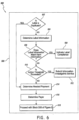
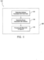
- Figure 6 through Figure 9 provide examples of processes for using the PASS computing system 301 for revenue protection and/or for specific aspects of revenue protection.
- Figure 6 depicts one embodiment of a process for using the PASS computing system 301 for revenue protection.
- the process 600 can be performed as a part of the process 500 for using the PASS computing system for item processing, and specifically, the process 600 can be performed as a part of block 506, shown in Figure 5 .
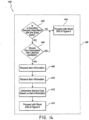
- the process 600 for using the PASS computing system 301 for revenue protection begins at decision state 602 when the PASS computing system 301 determines if the label is a duplicate.
- the determination of whether a label is a duplicate can involve comparing received scanned data with data stored in the memory 304 of the PASS computing system 301. The details of determining whether a label is a duplicate will be discussed at further length below.
- the process 600 proceeds to block 604 and the PASS computing system 301 determines the label information.
- the determination of the label information can be performed by the central computing unit 302. This determination can include, for example, decoding the scan data associated with the label to uncover label information embedded in the scanned data.
- the determining of the label information can include decoding the scan data associated with the label and using that data to query another database which includes label information.
- this database can be controlled and be a component of the PASS system 300, it can be a component of another system, and/or be a component of a third-party system.
- the determining of the label information can comprise, for example, determining information relating to services associated with the label, physical properties of the item associated with the label, the specified recipient of the label, the specified sender of the item associated with the label, and the origination point of the item.
- this information is embedded in the scan data
- the decoding of the scan data can provide this desired information.
- this information is not encoded in the scan data
- the decoding of the scan data may not provide this information. In that case the PASS computing system 301 may be directed to the database containing this information.
- not claimed item information can include information relating to the physical properties of the item, such as, for example, the size and weight of the item, and services requested for the item.
- not claimed label information can include user provided information relating to user asserted physical properties of the item and services requested by the user for the item.
- this determination of whether item information matches label information can include comparing the label information with collected item information.
- the item information can be generated by one or more of the modules of the PASS system 300 and can be stored in one or more of the databases of the memory 304.
- the item information can be generated before the determination of label information is made in block 604, and in some embodiments not claimed the item information can be generated and/or ascertained after the label information is determined in block 604.
- the item information can be generated at the prompting and/or at the instruction of the PASS computing system 301 and provided to one or more of the other modules of the PASS system 300.
- the item information can be generated at a PASS module 100 in response to instructions received from the PASS computing system 301.
- the item information can comprise a preliminary set of item information, and a confirmed set of item information.
- not claimed modules of the PASS system 300 can provide preliminary item information.
- the preliminary item is information that provides a non-determinative indication of some aspect relating to the item.
- preliminary information can be collected by a processing module 310 at the time that an item passes the processing module 310, and this information can be provided to the PASS computing system 301.
- the processing module 310 can be configured to scan the item and to ascertain certain physical parameters of the item, which can be stored as the preliminary item information. Due to tolerances of the processing module 310, the preliminary item information generated by the processing module 310 may not be determinative of whether the label information matches the item information because the processing module 310 may not accurate capture information relating to physical parameters of the item.
- the PASS computing system 301 can provide instructions to the PASS module 100 to verify item information at the time that the item is scanned at the PASS module 100.
- the confirmed item information can be generated by, for example, the testing module 116 of the PASS module. This information can then be communicated from the PASS module 100 to the PASS computing system 301, and the determination can be made as to whether the label information matches the item information.
- the process 600 moves to block 608 and indicates that the label is in compliance.
- an action threshold can include, for example, a number of times that a specific user has submitted items with label information that does not match the item information, a measure of the magnitude of the discrepancy, or any other threshold that provides an indication of intent to defraud the service provider.
- an action threshold can be established to differentiate between problems that can be resolved by the requesting of additional payment as compare with problems that require further, and potentially criminal, investigation.
- this determination can be made by the central computing unit 302 based on instructions and information stored in the memory 304, and can include, for example, determining the number of times that a user associated with the item has submitted items with label information that does not match the item information. If the number of times the user has submitted items with such label information is larger than the threshold, then the central computing unit 302 determines that the action threshold is exceeded.
- the process 600 proceeds to block 612 and the information is submitted for further processing, investigation, and/or to an investigative service.
- the investigative service can then use the provided information to build a case and/or to investigate the circumstances leading to the triggering of the investigation request.
- the process 600 likewise proceeds to block 614 and determines the required payment.
- the determination of the required payment can comprise comparing label information stored in the scan data with item information associated with the item. In some embodiments not claimed this information can include the physical properties of the item, as well as the services requested in association with the item. In some embodiments not claimed the physical properties of the item and the requested services can correspond to a service payment that can be the amount of money required to provide the requested services for an item with the current physical properties. This service payment can then be used to calculate a required payment. In some embodiments not claimed for example, the required payment can comprise the difference between the previously made payment and the service payment.
- the process 600 proceeds to block 616 and identifies and/or determines a payer.
- this determination can be made by one or several modules of the PASS system 300 including, for example, the PASS computing system 301, the PASS module 100, and/or the payment module 316.
- the process used to determine the payer will be discussed in further detail below.
- Figure 7 is a flowchart illustrating a method 700 for determining whether a label is a duplicate, as indicated in decision state 602 as indicated in Figure 6 . As seen in Figure 7 , the process 700 can be performed as a part of the process of decision state 602, shown in Figure 6 .
- the process 700 begins at block 702, wherein the received scan data is compared to the match database.
- this comparison can be performed by the central computing unit 302 which can, for example, access the match database found in the memory 304.
- the match database can comprise information relating to the labels that have already been used multiple times. Thus, if the received scan data matches that of a label found in the match database the use of a fraudulent label is identified.
- the process 700 proceeds to decision state 704 wherein the PASS computing system 301 determines if the comparison performed in decision state 702 produced a match. This determination can be made by the central computing unit 302 querying the memory 304 for match database information.
- the process 700 proceeds to block 706 and the PASS computing system 301 indicates that the label is a duplicate. After the label is indicated as a duplicate, the process 700 proceeds to block 708 and returns to block 614 of Figure 6 .
- the process 700 proceeds to block 710 and compares the received scan data to data in the scan database.
- the scan database can comprise information relating to all the scans generated in a designated time period.
- the scan database can be stored, for example, in the memory 304 of the PASS computing system 301.
- the process moves to decision state 712 and the PASS computing system 301 determines if comparison in decision state 712 has produced a match. In some embodiments according to the claims, this determination can be made by the central computing unit 302 of the PASS computing system 301. If it is determined that the scan data matches information found in the scan database, then the process 700 moves to block 706 and indicates that the label is a duplicate, after which the process 700 moves to block 708 and returns to block 614 of Figure 6 .
- indicating that the label is not a duplicate can include the central computing unit 302 providing such an indication to the memory 304 for inclusion in a database associated with the label.
- process 700 moves to block 716 and returns to block 604 of Figure 6 .
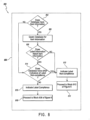
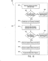
- Figure 8 illustrates a flowchart illustrating a process 800 relating to revenue protection. As seen in Figure 8 , the process 800 can be performed as a part of the decision state 606, shown in Figure 6 .
- Decision state 606 is the decision state in which the determination is made as to whether the label information matches the item information.
- the process 800 begins at decision state 802 wherein the PASS computing system 301 determines if the database includes item information. As mentioned above, in some embodiments not claimed item information can be added to a database before the scan data is generated, and in some embodiments not claimed item information can be generated in response to the generation of scan data.
- the process 800 proceeds to block 806 and the PASS computing system 301 queries the database containing the item information for the item information relating to the specific label in question. In some embodiments not claimed this query can be made by the central computing unit 302 to the memory 304.
- the process 800 proceeds to decision state 808 wherein the PASS computing system 301 determines if the label information matches the item information retrieved from the database.
- the accuracy of the components of the processing module 310 may not be sufficient to establish finalized item information.
- the determination of whether label information matches item information may provide for tolerances within which label information is deemed to match item information. For example, in some embodiments not claimed the item information identifying item weight may have been gathered using equipment having an accuracy within plus or minus one pound. In that case, the tolerance can be set so that the label information, read from the label on the item may be deemed to match the item information when the label information is within plus or minus one pound of the item information.
- the process 800 moves to block 810 and the PASS computing system 301 indicates label noncompliance.
- this indication of label noncompliance can comprise the central computing unit 302 updating a database in the memory 304 with an indication of label noncompliance.
- the process 800 proceeds to block 812 and returns to block 610 of Figure 6 .
- the process 800 proceeds to decision state 814 and the PASS computing system 301 determines whether the database has any other indicators of label noncompliance.
- the database may include other indicators of label noncompliance such as, for example, an indication that the labeling associated with the item indicated a flat rate box and/or flat rate package and that the parameters of the item associated with the label do not match those flat rate indications.
- the process 800 proceeds to block 810 and the PASS computing system 301 indicates label noncompliance which, as mentioned above, can include the central computing unit 302 adding an indicator to a database in the memory 304 of the noncompliance. After the label noncompliance is indicated, the process 800 proceeds to block 812 and returns to block 610 of Figure 6 .
- the process 800 proceeds to block 816 and the PASS computing system 301 indicates label compliance.
- the indication of label compliance can comprise the central computing unit 302 adding an indicator to a database in the memory 304 of the label compliance. After the label compliance is indicated, then the process 800 proceeds to block 818 and returns to block 608 of Figure 6 .
- FIG 9 is a flowchart illustrating an embodiment of a process 900 for determining a payer, as indicated in block 616 of Figure 6 .
- the process 900 can be performed as a part of the process 600, and specifically, the process 600 can be performed as a part of block 616, shown in Figure 6 .
- This process 900 is a part of revenue protection, and can be performed by the PASS system 300 and/or components and/or modules of the PASS system 300 including, for example, the PASS computing system 301.
- the process 900 begins at decision state 902 wherein the PASS computing system 301 determines if the sender is ascertainable.
- the determination of whether the sender is ascertainable can include querying a database found in the memory 304 for information relating to potential previous duplicate uses of the label and/or account information. If the label has been previously used, as indicated by an indication in a database in the memory 304 identifying the label as a duplicate, the sender can be ascertained by comparing the current sender with information from the database in the memory 304 identifying the previous sender. In the event the current sender is the same as the previous sender, it is assumed that the previous and current senders are the same and are the source of the duplication. Thus, if the previous and current senders are the same, then the sender is ascertainable. If the previous and current senders are not the same, then the sender is not ascertainable.
- the process 900 proceeds to block 904 and the PASS computing system 301 indicates the sender as the payer.
- the indicating of the sender as the payer can comprise, for example, the central computing unit 302 sending instructions to the memory 304 to update a database to indicate that the sender is the payer.
- the process 900 proceeds to block 906 and proceeds to block 618 in Figure 6 .
- decision state 902 if the sender is not ascertainable, then the process proceeds to decision state 908 and the PASS computing system 301 determines if the intended recipient is ascertainable.
- the process 900 proceeds to block 910 and the PASS computing system 301 indicates the recipient as the payer.
- the indicating of the recipient as the payer can comprise the central computing unit 302 sending instructions to the memory to add an indicator to a database indicating that the recipient is the payer. The process then proceeds to block 906 and returns to block 618 in Figure 6 .
- the process 900 proceeds to block 912 and the PASS computing system 301 indicates that no payer is ascertainable.
- the PASS computing system 301 indicates that no payer is ascertainable.
- not claimed indicating that no payer is ascertainable can comprise the central computing unit 302 providing instructions to the memory 304 to update a database with an indication that no payer is ascertainable.
- the process then proceeds to block 914 and scan data and information relating to the label is submitted to the investigative service. In some embodiments not claimed and as an alternative to submitting information to the investigative service, the item is seized and disposed of.
- Figure 10 depicts a flowchart illustrating a process 1000 for using a PASS system 300 to redirect an enroute item.
- the process 1000 can be performed as a part of the process 500 for using the PASS computing system for item processing, and specifically, the process 1000 can be performed as a part of block 506, shown in Figure 5 .
- a sender may decide to request different services and/or to redirect the item.
- the process 1000 in Figure 10 provides the details for how this redirection may be accomplished.
- the process 1000 begins at decision state 1002 and the PASS computing system 301 determines if scan data is associated with a redirect service. In some embodiments not claimed this determination can include the central computing unit 302 querying the memory 304 for information relating to requested services. In some embodiments not claimed the memory 304 may include an indication requesting a redirect of an item. Such a request may have originated, for example, from the sender so as to cause the entry of the redirect request indication in the memory 304. If it is determined that the scan data is not associated with redirect, then the process 1000 proceeds to block 1004 and proceeds with processing.
- decision state 1006 determines if redirect is requested.
- the decision state 1006 differentiates itself from the decision in decision state 1002 in that an item may be associated with redirect services, and thus it may qualify for redirect services, but redirect services may not have been requested in connection with the specified item.
- not claimed determining whether redirect is requested can comprise a central computing unit 302 querying the memory 304 for information relating to whether the redirect is requested. If the redirect is requested, the memory 304 can comprise information indicating such. If such information is not discovered in the memory, then the process 1000 proceeds to block 1004 and proceeds with processing.
- the process 1000 proceeds to block 1010 and proceeds with the activities of block 508 of Figure 5 .
- process 1000 for using a PASS system 300 can comprise more or fewer steps than those illustrated herein.
- steps illustrated herein can be performed in the same order or a different order than described herein.
- process 1000 for performing redirect services is not limited to the specific embodiment described herein.
- Figure 11 is a flowchart illustrating a process 1100 for using a PASS system 300 in item processing. Specifically, the process 1100 relates to using a PASS system 300 for sorting items into routes. As seen in Figure 11 , the process 1100 can be performed as a part of the process 500 for using the PASS computing system for item processing, and specifically, the process 1100 can be performed as a part of block 506, shown in Figure 5 .
- not claimed items are sorted into routes to facilitate delivery.
- this sorting is traditionally done by a skilled person; however, changes in routes and/or loss of trained individuals can cause significant difficulties. Further, relying on skilled individuals to sort items into routes prevents the possibility of easily having different routes for different days of the week or for different circumstances.
- the process 1100 eliminates the need for the skilled individual to make sorting decisions and allows for dynamic routing.
- the process 1100 begins in block 1104 and the PASS computing system 301 determines the address associated with the scan data.
- this determination can include, for example, decoding the scan data to ascertain the intended recipient of the item.
- determining the address associated with the scan data can comprise querying a database including, for example, a third-party database, with scan data to determine an address that is associated with the scan data.
- determining the route associated with the address can comprise, for example, querying an address database and/or a route database.
- an address database and/or a route database is queried to determine which delivery route the address associated with the scan data is associated with.
- block 1106 provides for the possibility of assigning an address to different routes depending on the circumstances in which the item is to be delivered such as, for example, the date of delivery, the day of the week of delivery, the number of items to be delivered, and/or the number of people available for delivery of items.
- the determination of which route is associated with the address can be made by the central computing unit 302, and the query of the address and/or route database can be made by querying the memory 304 and querying databases found in the memory 304.
- not claimed items are sorted not only into delivery routes, but also into delivery sequences.
- a delivery sequence can be, for example, a sorting of items to match a delivery order of the items; thus, for example, the items are ordered such that the first item to be delivered is positioned before the tenth item to be delivered in the delivery sequence.
- Figure 12 is a flowchart illustrating a process for using a PASS system 300 to sort items into a delivery sequence.
- the process 1200 can be performed as a part of the process 500 for using the PASS computing system for item processing, and specifically, the process 1200 can be performed as a part of block 506, shown in Figure 5 .
- the process 1200 begins at block 1204 and the PASS computing system 301 determines the address associated with the scan data. In some embodiments not claimed this determination can include, for example, decoding the scan data to ascertain the intended recipient of the item. In some embodiments not claimed determining the address associated with the scan data can comprise querying a database including, for example, a third-party database, with scan data to determine an address that is associated with the scan data.
- the process 1200 moves to block 1206 and the PASS computing system 301 determines the delivery sequence position associated with the address.
- this determination can comprise the central computing unit 302 querying the memory 304 for delivery sequence information, and for information relating to the position of an address within the delivery sequence.
- this query can further comprise requesting information relating to other scanned items and the desired relative position of the presently scanned item to the previously scanned items.
- the process 1200 moves to block 1208 and proceeds with block 508 of Figure 5 .
- Figure 13 is a flowchart illustrating a process 1300 for using a PASS system 300 to manage tasks associated with an item.
- the process 1300 can be performed as a part of the process 500 for using the PASS computing system for item processing, and specifically, the process 1300 can be performed as a part of block 506, shown in Figure 5 .
- the process 1300 begins at block 1304 and the PASS computing system 301 adds scan data to a database.
- the central computing unit 302 can add scan data to a database by providing instructions to the memory 304 to update a database with information relating to the scan data.
- the process 1300 then proceeds to block 1306 and the PASS computing system 301 determines whether there are any associated tasks related to the scan data.
- this determination can comprise the central computing unit 302 querying the memory 304 for information associated with the scan data.
- the central computing unit 302 can determine that there are no associated tasks related to the scan data.
- the central computing unit 302 can determine whether the information associated with the scan data relates to associated tasks.
- the central computing unit 302 can determine that there are no associated tasks related to the scan data.
- the central computing unit 302 can determine that there are associated tasks related to the scan data.
- not claimed these tasks can be performed at the occurrence of another event.
- a recipient's signature can be received at the time that an item is delivered.
- the process 1300 proceeds to block 1310 and the PASS computing system generates a prompt for the associated task.
- the generation of a prompt for the associated task can comprise the central computing unit 302 querying the memory 304 for instructions related to the associated task. The central computing unit 302 can then execute these instructions and generate a prompt to remind the user of the PASS system 300 to perform the associated task.
- Figure 14 is a flowchart illustrating a process 1400 for using a PASS system 300 for generating sampling-based information.
- the process 1400 can be performed as a part of the process 500 for using the PASS computing system for item processing, and specifically, the process 1400 can be performed as a part of block 506, shown in Figure 5 .
- the process 1400 can be performed by a variety of modules and/or components of the PASS system 300 including, for example, the PASS computing system 301. In some embodiments not claimed the process 1400 can be configured to randomly sample items received within the PASS system 300 and use the random sampling to generate data that is representative of a larger group of items.
- the process 1400 moves to decision state 1406 and the PASS computing system 301 determines if the item associated with the label should be sampled. In some embodiments not claimed this determination can be made by the central computing unit 302, and can be specifically made by the querying of a random number generator to determine whether or not the item associated with the label should be sampled. In some embodiments not claimed certain outcomes of the random number generator can designate an item for sampling and/or for not sampling. In the event that an item is not designated for sampling, then the process 1400 moves to block 1404 and proceeds with block 508 of Figure 5 .
- the process 1400 moves to block 1408 and the PASS computing system 301 requests item information.
- this request of item information can be made to, for example, the PASS module 100 and/or the processing module 310.
- the requested item information can comprise, for example, physical parameters of the items such as, for example, the weight of the item, the dimensions of the item, the contents of the item, and/or any other desired information relating to the item.
- the determination of service costs based on item information can further comprise determining the batch of items from which the scanned data was taken.
- the scanned data can relate to one of a batch of items.
- the service costs associated with the item can be added with other randomly sampled and generated services costs to determine an average per piece service cost for the batch. This average per piece service cost for the batch can be used to then calculate the overall total cost for providing services to the batch of items.
- the process 1500 begins at block 1502 and the PASS computing system 301 determines the address associated with the scan data.
- this determination can include, for example, extracting address information embedded in the scan data and/or querying a database with the scan data to determine the address associated with the scan data.
- this step can be performed by the central computing unit 302 which can query the memory 304 for address information associated with the scan data.
- the PASS computing system 301 can query a database associated with other systems which can be located inside the PASS system 300, external to the PASS system 300, and/or controlled by a third party.
- the process 1500 proceeds to decision state 1506 and the PASS computing system 301 determines if the scan data address is in the change-of-address database.
- the change-of-address database can be located in the memory 304, can be located external to the PASS computing system 301, can be located external to the PASS system 300, and/or can be controlled by a third party.
- the central computing unit 302 can query the appropriate database to determine if the address associated with the scan data is in the change-of-address database. If the address associated with the scan data is not in the change-of-address database, then the process 1500 can move to block 1508 and proceed to block 508 of Figure 5 .
- the process 1500 moves to block 1512 and the PASS computing system 301 determines the item recipient associated with the scan data.
- the item recipient information can be embedded in the scan data, in some embodiments not claimed the item recipient information may not be associated in the scan data, but can be associated with the scan data in a separate database.
- the recipient can be determined by retrieving information embedded in the scanned data, and in other embodiments not claimed the item recipient can be determined by querying a database with information from the scan data to determine the item recipient associated with the scan data.
- the process 1500 moves to block 1518 and the PASS computing system 301 requests updated address information.
- the request for updated address information can comprise the central computing unit 302 querying the change-of-address database for updated address information.
- the process 1500 proceeds to block 1520 and the PASS computing system 301 receives the updated address information. After the updated address information has been received, the process 1500 moves to block 1522 and proceeds with block 508 of Figure 5 .
- process 1500 can include more or fewer steps than those outlined above.
- process 1500 can be performed in the same order outlined above or in a different order.
- Figure 16 is a flowchart illustrating one embodiment of a process 1600 for using the PASS system 300 to track data relating to an employee.
- the process 1600 can be performed by the PASS system 300 and more specifically, by the PASS computing system 301.
- the process 1600 begins at block 1602 and the PASS computing system 301 receives employee scan data.
- an employee can scan some identifying badge into the PASS system 300.
- this scan can be made by the PASS module 100 and/or any other scanning unit within the PASS system.
- the process 1600 moves to block 1604 and the PASS computing system 301 identifies the employee associated with the scan data.
- the identification of the employee associated with the scan data can be achieved by the central computing unit 302 querying the memory 304 for employee information.
- the memory 304 can comprise a database listing employees and their associated scanned badge.
- the process 1600 moves to block 1610 and the PASS computing system 301 analyzes the item scan data.
- this analysis can be performed by the central computing unit 302 and can comprise querying the memory for information relating to the employee scan data.
- this analysis can include, for example, adding the entirety of items scanned associated with the employee scan data, determining the length of time that an employee was performing work associated with the PASS system 300, determining the number of item scans performed by the employee in a specified time, and/or any other information relating to the item scan data associated with the employee.
- the process 1600 moves to block 1612 and the PASS computing system 301 provides item scan data and analysis results.
- the PASS computing system 301 can provide item scan data and analysis results to, for example, another module of the PASS system 300, such as the administration module 312.
- this scan data and analysis results can then be used to determine workforce efficiency, employee efficiency, for scheduling purposes, and to determine the number of employees required to perform any designated task.
- the receipt of the action request can also include a receipt of an indication and/or identification of the label associated with the action request.
- the process 1700 can proceed to block 1706 and the PASS computing system 301 can receive the scan data.
- the scan data can be received from one of the modules of the PASS system 300 such as, for example, the PASS module 100 and/or the processing module 310.
- the process 1700 moves to decision state 1708 and the PASS computing system 301 determines if the scan data matches information in the action database.
- this determination can be performed by the central computing unit 302, which can compare the scan data received from one of the modules of the PASS system 300 with the action database.
- this comparison can comprise querying the memory 304 for information from the action database to determine if the scan data matches the action database.
- the process 1700 moves to block 1712 and the PASS computing system 301 transmits the requested action information to the scanner module 108.
- this transmission can be performed by the central computing unit 302 which can communicate with, for example, the processing module 310 and/or PASS module 100 to provide instructions to perform the requested action.
- the process 1700 can then proceed to an additional step not shown in Figure 17 in which the PASS computing system 301 receives confirmation that the requested action has been performed, and in some embodiments not claimed the PASS computing system 301 can then update the action database to indicate that the requested action was completed.
- process 1700 illustrated in Figure 17 can comprise more or fewer steps than those specifically illustrated in Figure 17 .
- steps of process 1700 can be performed in the same order as illustrated in Figure 17 or in a different order.
- the technology is operational with numerous other general purpose or special purpose computing system environments or configurations.
- Examples of well known computing systems, environments, and/or configurations that may be suitable for use with the invention include, but are not limited to, personal computers, server computers, hand-held or laptop devices, multiprocessor systems, microprocessor-based systems, programmable consumer electronics, network PCs, minicomputers, mainframe computers, distributed computing environments that include any of the above systems or devices, and the like.
- instructions refer to computer-implemented steps for processing information in the system. Instructions can be implemented by a processor which can comprise software, firmware or hardware and include any type of programmed step undertaken by components of the system.
- a processor may be any conventional general purpose single- or multichip processor and/or microprocessor such as a Pentium ® processor, a Pentium ® Pro processor, a 8051 processor, a MIPS ® processor, a Power PC ® processor, or an Alpha ® processor.
- the microprocessor may be any conventional special purpose microprocessor such as a digital signal processor or a graphics processor.
- the microprocessor typically has conventional address lines, conventional data lines, and one or more conventional control lines.
- the system may be used in connection with various operating systems such as Linux ® , UNIX ® or Microsoft Windows ® .
- the system control may be written in any conventional programming language such as C, C++, BASIC, Pascal, or Java, and ran under a conventional operating system.
- C, C++, BASIC, Pascal, Java, and FORTRAN are industry standard programming languages for which many commercial compilers can be used to create executable code.
- the system control may also be written using interpreted languages such as Perl, Python or Ruby.
Landscapes
- Engineering & Computer Science (AREA)
- General Engineering & Computer Science (AREA)
- Management, Administration, Business Operations System, And Electronic Commerce (AREA)
- Image Analysis (AREA)
- Facsimiles In General (AREA)
- Image Input (AREA)
Claims (22)
- Artikelverteilungssystem (300) zur Artikelverarbeitung, das Folgendes umfasst:eine Kamera, die zum Aufnehmen eines Bildes eines Etiketts auf einem von einer Artikelverarbeitungsanlage in dem Artikelverteilungssystem (300) verarbeiteten Artikel geeignet ist, wobei sich auf dem Etikett Scandaten befinden;ein Rechensystem (301), das Folgendes umfasst:einen Speicher (304), der Folgendes umfasst:eine erste Datenbank (306), die zum Speichern von Scandaten geeignet ist, die einen Indikator für ein Etikett umfassen, das bereits in Assoziation mit mindestens zwei verschiedenen Artikeln benutzt wurde; undeine zweite Datenbank (308), die zum Speichern von Scandaten geeignet ist, die einen Indikator für ein Etikett umfassen, das noch nicht in Assoziation mit mindestens zwei verschiedenen Artikeln benutzt wurde;einen Prozessor (302) in Kommunikation mit der Kamera und dem Speicher (304), wobei der Prozessor (302) konfiguriert ist zum:Erzeugen von Scandaten aus dem aufgenommenen Bild des Etiketts;Vergleichen von Informationen aus den Scandaten mit dem Indikator in der ersten Datenbank (306), um eine Übereinstimmung mit dem Etikett zu identifizieren, das bereits in Assoziation mit den mindestens zwei verschiedenen Artikeln benutzt wurde;Bewirken, wenn eine Übereinstimmung in der ersten Datenbank (306) identifiziert wird, dass die Artikelverarbeitungsanlage mindestens eines von Umleiten des Artikels von einem ersten Weg zu einem ersten Ziel auf einen zweiten Weg zu einem zweiten Ziel, Ziehen des Artikels aus dem Verkehr, Testen und/oder Nehmen einer Probe des Artikels, Beschlagnahmen des Artikels oder Bewerten von Inhalt und/oder physikalischen Charakteristiken des Artikels durchführt;Vergleichen, wenn keine Übereinstimmung in der ersten Datenbank (306) identifiziert wird, der Informationen aus den Scandaten mit dem Indikator in der zweiten Datenbank (308), um eine Übereinstimmung mit einem Etikett zu identifizieren, das nicht bereits in Assoziation mit mindestens zwei verschiedenen Artikeln benutzt wurde;Übertragen, wenn eine Übereinstimmung in der zweiten Datenbank (308) identifiziert wird, der Scandaten von der zweiten Datenbank (308) zur ersten Datenbank (306); undSpeichern, wenn keine Übereinstimmung in der zweiten Datenbank (308) identifiziert wird, der Scandaten in der zweiten Datenbank (308).
- System nach Anspruch 1, wobei die Kamera zum Aufnehmen eines Bildes des Artikels konfiguriert ist, wenn ein Etikett auf dem Artikel für die Kamera innerhalb eines definierten dreidimensionalen Raums sichtbar ist.
- System nach Anspruch 1, wobei der Prozessor ferner zum Übermitteln der Scandaten an eine zentrale Recheneinheit konfiguriert ist, die zum Speichern von Informationen und Anweisungen in Bezug auf den Artikel konfiguriert ist.
- System nach Anspruch 3, wobei der Prozessor ferner zum Empfangen von Anweisungen in Bezug auf einen Dispositionsort des Artikels von der zentralen Recheneinheit konfiguriert ist.
- System nach Anspruch 1, das ferner einen Wagen und einen Ausleger umfasst, wobei der Ausleger an einem ersten Ende mit dem Wagen verbunden ist und wobei ein zweites Ende des Auslegers aus dem Wagen herausragt und die Kamera sich am zweiten Ende des Auslegers befindet.
- System nach Anspruch 1, wobei eine Ausgabe eine akustische und/oder visuelle Ausgabe umfasst.
- System nach Anspruch 6, wobei die visuelle Ausgabe ein farbiges Licht umfasst.
- System nach Anspruch 1, wobei die Scandaten den Artikel eindeutig identifizieren.
- System nach Anspruch 1, wobei das Etikett Informationen zum Bestimmen von Artikelverarbeitungsanweisungen umfasst.
- System nach Anspruch 9, wobei die Artikelverarbeitungsanweisungen Aufgaben in Bezug auf den Artikel identifizieren.
- System nach Anspruch 1, wobei der Prozessor ferner konfiguriert ist zum:Bestimmen einer physikalischen Charakteristik des Artikels;Feststellen, ob Informationen aus den Scandaten der physikalischen Charakteristik des Artikels entsprechen; undBereitstellen von Anweisungen zum weiteren Verarbeiten des Artikels auf der Basis davon, ob die Informationen aus den Scandaten der physikalischen Charakteristik des Artikels entsprechen.
- System nach Anspruch 1, wobei der Prozessor, wenn keine Übereinstimmung identifiziert wird, ferner konfiguriert ist zum:Identifizieren eines Indikators für ein Etikett, das als in einem bestimmten Zeitrahmen gescannt identifiziert wird;Feststellen, ob Informationen aus den Scandaten dem Indikator eines Etiketts entsprechen, das als in einem bestimmten Zeitrahmen gescannt identifiziert wird; undGeben von Anweisungen zur weiteren Verarbeitung des Artikels auf der Basis davon, ob Informationen aus den Scandaten dem Indikator eines Etiketts entsprechen, das als in einem bestimmten Zeitrahmen gescannt identifiziert wird.
- Verfahren (700) zur Artikelverarbeitung in einem Artikelverteilungssystem (300), das Folgendes beinhaltet:Aufnehmen, durch ein Bildgebungsgerät, eines Bildes eines Etiketts auf einem Artikel, der von einer Artikelverarbeitungsanlage im Artikelverteilungssystem (300) verarbeitet wird, wobei sich auf dem Etikett Scandaten befinden;Erzeugen von Scandaten aus dem aufgenommenen Bild des Etiketts durch einen Prozessor (302) eines Rechensystems (301);Vergleichen von Informationen aus den Scandaten mit einem Indikator für ein Etikett in einer ersten Datenbank (306), das bereits in Assoziation mit mindestens zwei verschiedenen Artikeln benutzt wurde, um eine Übereinstimmung zu identifizieren;Bewirken, wenn eine Übereinstimmung zwischen dem Etikett auf dem Artikel und dem bereits in Assoziation mit den mindestens zwei verschiedenen Artikeln benutzten Etikett identifiziert wird, dass das Rechensystem (301) das Etikett als gefälscht identifiziert;Vergleichen, wenn keine Übereinstimmung in der ersten Datenbank (306) identifiziert wird, der Informationen aus den Scandaten mit einem Indikator in einer zweiten Datenbank (308), um eine Übereinstimmung mit einem Etikett zu identifizieren, das nicht bereits in Assoziation mit mindestens zwei verschiedenen Artikeln benutzt wurde;Bewirken, wenn eine Übereinstimmung in der zweiten Datenbank (308) identifiziert wird, dass das Rechensystem (301) das Etikett als gefälscht identifiziert; undBewirken, wenn keine Übereinstimmung in der zweiten Datenbank (308) identifiziert wird, dass das Rechensystem (301) das Etikett als nicht gefälscht identifiziert und Speichern der Scandaten in der zweiten Datenbank (308).
- Verfahren nach Anspruch 13, das ferner Folgendes beinhaltet:Erkennen der Anwesenheit des Artikels innerhalb eines definierten dreidimensionalen Bildes; undAuslösen der Aufnahme des Bildes als Reaktion auf das Erkennen der Anwesenheit des Artikels.
- Verfahren nach Anspruch 13, das ferner das Aktualisieren einer lokalen Datenbank mit den Scandaten beinhaltet.
- Verfahren nach Anspruch 15, wobei die lokale Datenbank mit einem Indikator für das aufgenommene Bild aktualisiert wird.
- Verfahren nach Anspruch 13, das ferner das Bereitstellen von Informationen in Bezug auf das aufgenommene Bild beinhaltet.
- Verfahren nach Anspruch 17, wobei die Informationen eine Darstellung des aufgenommenen Bildes umfassen.
- Verfahren nach Anspruch 13, wobei das Etikett Informationen zur Bestimmung von Artikelverarbeitungsanweisungen enthält.
- Verfahren nach Anspruch 19, wobei die Artikelverarbeitungsanweisungen Aufgaben in Bezug auf den Artikel identifizieren.
- Verfahren nach Anspruch 13, das ferner Folgendes beinhaltet:Bestimmen einer physikalischen Charakteristik des Artikels;Feststellen, ob Informationen aus den Scandaten der physikalischen Charakteristik des Artikels entsprechen; undGeben von Anweisungen für die weitere Verarbeitung des Artikels auf der Basis davon, ob die Informationen aus den Scandaten der physikalischen Charakteristik des Artikels entsprechen.
- Verfahren nach Anspruch 13, wobei das Verfahren, wenn keine Übereinstimmung identifiziert wird, ferner Folgendes beinhaltet:Identifizieren eines Indikators für ein Etikett, das als in einem bestimmten Zeitrahmen gescannt identifiziert wird;Feststellen, ob Informationen aus den Scandaten dem Indikator für ein Etikett entsprechen, das als in einem bestimmten Zeitrahmen gescannt identifiziert wird; undGeben von Anweisungen für die weitere Verarbeitung des Artikels auf der Basis davon, ob Informationen aus den Scandaten dem Indikator für ein Etikett entsprechen, das als in einem bestimmten Zeitrahmen gescannt identifiziert wird.
Applications Claiming Priority (3)
| Application Number | Priority Date | Filing Date | Title |
|---|---|---|---|
| US13/834,272 US9795997B2 (en) | 2013-03-15 | 2013-03-15 | Systems, methods and devices for item processing |
| PCT/US2014/024251 WO2014150794A2 (en) | 2013-03-15 | 2014-03-14 | Systems, methods and devices for item processing |
| EP14767369.3A EP2973221A4 (de) | 2013-03-15 | 2014-03-14 | Systeme, verfahren und vorrichtungen zur elementverarbeitung |
Related Parent Applications (1)
| Application Number | Title | Priority Date | Filing Date |
|---|---|---|---|
| EP14767369.3A Division EP2973221A4 (de) | 2013-03-15 | 2014-03-14 | Systeme, verfahren und vorrichtungen zur elementverarbeitung |
Publications (3)
| Publication Number | Publication Date |
|---|---|
| EP3404579A2 EP3404579A2 (de) | 2018-11-21 |
| EP3404579A3 EP3404579A3 (de) | 2019-07-24 |
| EP3404579B1 true EP3404579B1 (de) | 2024-06-12 |
Family
ID=51527214
Family Applications (4)
| Application Number | Title | Priority Date | Filing Date |
|---|---|---|---|
| EP18182066.3A Withdrawn EP3416102A3 (de) | 2013-03-15 | 2014-03-14 | Systeme, verfahren und vorrichtungen zur artikelverarbeitung |
| EP18182069.7A Withdrawn EP3404580A3 (de) | 2013-03-15 | 2014-03-14 | Systeme, verfahren und vorrichtungen zur artikelverarbeitung |
| EP14767369.3A Withdrawn EP2973221A4 (de) | 2013-03-15 | 2014-03-14 | Systeme, verfahren und vorrichtungen zur elementverarbeitung |
| EP18182067.1A Active EP3404579B1 (de) | 2013-03-15 | 2014-03-14 | Systeme, verfahren und vorrichtungen zur artikelverarbeitung |
Family Applications Before (3)
| Application Number | Title | Priority Date | Filing Date |
|---|---|---|---|
| EP18182066.3A Withdrawn EP3416102A3 (de) | 2013-03-15 | 2014-03-14 | Systeme, verfahren und vorrichtungen zur artikelverarbeitung |
| EP18182069.7A Withdrawn EP3404580A3 (de) | 2013-03-15 | 2014-03-14 | Systeme, verfahren und vorrichtungen zur artikelverarbeitung |
| EP14767369.3A Withdrawn EP2973221A4 (de) | 2013-03-15 | 2014-03-14 | Systeme, verfahren und vorrichtungen zur elementverarbeitung |
Country Status (4)
| Country | Link |
|---|---|
| US (4) | US9795997B2 (de) |
| EP (4) | EP3416102A3 (de) |
| CN (4) | CN105308619B (de) |
| WO (1) | WO2014150794A2 (de) |
Families Citing this family (19)
| Publication number | Priority date | Publication date | Assignee | Title |
|---|---|---|---|---|
| US8340812B1 (en) * | 2007-08-30 | 2012-12-25 | Amazon Technologies, Inc. | Optimization of packaging sizes |
| US9795997B2 (en) * | 2013-03-15 | 2017-10-24 | United States Postal Service | Systems, methods and devices for item processing |
| US9604256B2 (en) * | 2013-09-17 | 2017-03-28 | Logical Turn Services Inc. | Intelligent mail recovery tool |
| US10078811B2 (en) * | 2013-11-29 | 2018-09-18 | Fedex Corporate Services, Inc. | Determining node location based on context data in a wireless node network |
| US11501244B1 (en) * | 2015-04-06 | 2022-11-15 | Position Imaging, Inc. | Package tracking systems and methods |
| US10853757B1 (en) | 2015-04-06 | 2020-12-01 | Position Imaging, Inc. | Video for real-time confirmation in package tracking systems |
| US10148918B1 (en) | 2015-04-06 | 2018-12-04 | Position Imaging, Inc. | Modular shelving systems for package tracking |
| US11416805B1 (en) * | 2015-04-06 | 2022-08-16 | Position Imaging, Inc. | Light-based guidance for package tracking systems |
| US11436553B2 (en) | 2016-09-08 | 2022-09-06 | Position Imaging, Inc. | System and method of object tracking using weight confirmation |
| US10634506B2 (en) | 2016-12-12 | 2020-04-28 | Position Imaging, Inc. | System and method of personalized navigation inside a business enterprise |
| US10634503B2 (en) | 2016-12-12 | 2020-04-28 | Position Imaging, Inc. | System and method of personalized navigation inside a business enterprise |
| US12190542B2 (en) | 2017-01-06 | 2025-01-07 | Position Imaging, Inc. | System and method of calibrating a directional light source relative to a camera's field of view |
| US11120392B2 (en) | 2017-01-06 | 2021-09-14 | Position Imaging, Inc. | System and method of calibrating a directional light source relative to a camera's field of view |
| WO2018229791A1 (en) * | 2017-06-16 | 2018-12-20 | Flipkart Internet Private Limited | Sorting assistance system and method thereof |
| US11361273B2 (en) * | 2017-10-09 | 2022-06-14 | United States Postal Service | Use of geospatial coordinate systems for tracking item delivery |
| US11014123B2 (en) * | 2018-05-29 | 2021-05-25 | Hand Held Products, Inc. | Methods, systems, and apparatuses for monitoring and improving productivity of a material handling environment |
| CN113424197A (zh) | 2018-09-21 | 2021-09-21 | 定位成像有限公司 | 机器学习辅助自改进对象识别系统和方法 |
| WO2020146861A1 (en) | 2019-01-11 | 2020-07-16 | Position Imaging, Inc. | Computer-vision-based object tracking and guidance module |
| US20210279679A1 (en) * | 2020-03-04 | 2021-09-09 | United States Postal Service | Disposition of items based on item image datasets |
Family Cites Families (65)
| Publication number | Priority date | Publication date | Assignee | Title |
|---|---|---|---|---|
| US3419128A (en) * | 1966-10-07 | 1968-12-31 | Roy F. Leonard | Conveyor system |
| JPH0696100A (ja) * | 1992-09-09 | 1994-04-08 | Mitsubishi Electric Corp | 遠隔取引システム |
| AU1333895A (en) * | 1993-11-30 | 1995-06-19 | Raymond R. Burke | Computer system for allowing a consumer to purchase packaged goods at home |
| US5917925A (en) * | 1994-04-14 | 1999-06-29 | Moore; Lewis J. | System for dispensing, verifying and tracking postage and other information on mailpieces |
| US5758257A (en) * | 1994-11-29 | 1998-05-26 | Herz; Frederick | System and method for scheduling broadcast of and access to video programs and other data using customer profiles |
| US5770841A (en) * | 1995-09-29 | 1998-06-23 | United Parcel Service Of America, Inc. | System and method for reading package information |
| US6246794B1 (en) * | 1995-12-13 | 2001-06-12 | Hitachi, Ltd. | Method of reading characters and method of reading postal addresses |
| US5870203A (en) * | 1996-03-15 | 1999-02-09 | Sony Corporation | Adaptive lighting control apparatus for illuminating a variable-speed web for inspection |
| AU6011698A (en) | 1996-11-15 | 1998-06-03 | Burford Corporation | Video recognition system |
| US6298173B1 (en) | 1997-10-03 | 2001-10-02 | Matsushita Electric Corporation Of America | Storage management system for document image database |
| CN1238808C (zh) * | 1998-03-24 | 2006-01-25 | 计量仪器股份有限公司 | 识别与测量通过激光扫描通道的包的自动系统和方法 |
| WO2000019382A1 (en) * | 1998-09-29 | 2000-04-06 | Stamps.Com, Inc. | On-line postage system |
| AU4506801A (en) * | 1999-11-16 | 2001-06-18 | United States Postal Service | Method for authenticating mailpieces |
| US6778683B1 (en) * | 1999-12-08 | 2004-08-17 | Federal Express Corporation | Method and apparatus for reading and decoding information |
| US8701857B2 (en) | 2000-02-11 | 2014-04-22 | Cummins-Allison Corp. | System and method for processing currency bills and tickets |
| US20010034608A1 (en) | 2000-02-22 | 2001-10-25 | Marc Gendreau | Shipping method and system |
| US20060106717A1 (en) * | 2000-05-25 | 2006-05-18 | Randle William M | End to end check processing from capture to settlement with security and quality assurance |
| US7707124B2 (en) * | 2000-08-28 | 2010-04-27 | Pitney Bowes Inc. | Mail piece verification system having forensic accounting capability |
| US6965324B1 (en) * | 2000-10-21 | 2005-11-15 | Robert W. Suggs, Sr. | Automotive picture and data acquisition center and method |
| US6325283B1 (en) * | 2000-10-25 | 2001-12-04 | Soy Chu | Computer implemented program for inventory management |
| JP2004526232A (ja) | 2001-01-18 | 2004-08-26 | フェデラル エクスプレス コーポレイション | パッケージ上の情報の読取り及び復号化 |
| US7111787B2 (en) * | 2001-05-15 | 2006-09-26 | Hand Held Products, Inc. | Multimode image capturing and decoding optical reader |
| US7095875B2 (en) * | 2001-05-15 | 2006-08-22 | Lockheed Martin Corporation | Method and system for address result arbitration |
| US6942151B2 (en) * | 2001-05-15 | 2005-09-13 | Welch Allyn Data Collection, Inc. | Optical reader having decoding and image capturing functionality |
| US7883002B2 (en) * | 2001-07-20 | 2011-02-08 | Ebay Inc. | Automated listing management |
| US7458612B1 (en) * | 2001-08-01 | 2008-12-02 | Stamps.Com Inc. | Postal shipping label |
| US7080777B2 (en) * | 2001-08-14 | 2006-07-25 | Ikan Technologies Inc. | Networked disposal and information distribution apparatus |
| US8463716B2 (en) * | 2001-11-20 | 2013-06-11 | Psi Systems, Inc. | Auditable and secure systems and methods for issuing refunds for misprints of mail pieces |
| US20030101143A1 (en) * | 2001-11-20 | 2003-05-29 | Psi Systems, Inc. | Systems and methods for detecting postage fraud using a unique mail piece indicium |
| US7831518B2 (en) * | 2001-11-20 | 2010-11-09 | Psi Systems, Inc. | Systems and methods for detecting postage fraud using an indexed lookup procedure |
| JP2003162755A (ja) * | 2001-11-27 | 2003-06-06 | Great Information Kk | プリペイドカード情報発行システム、通話料決済システム、通信料決済システム、及び代金決済システム |
| US6696656B2 (en) * | 2001-11-28 | 2004-02-24 | Pitney Bowes Inc. | Method of processing return to sender mailpieces using voice recognition |
| US20030115162A1 (en) | 2001-12-14 | 2003-06-19 | Konick Michael Edward | System and method for mail processing with verified sender identity |
| US7969306B2 (en) | 2002-01-11 | 2011-06-28 | Sap Aktiengesellschaft | Context-aware and real-time item tracking system architecture and scenarios |
| US6866194B2 (en) * | 2002-01-23 | 2005-03-15 | Nestec, Ltd. | Systems and methods for inventory management |
| US20030212602A1 (en) * | 2002-05-13 | 2003-11-13 | Kurt Schaller | Order and inventory management system |
| WO2003098533A1 (en) * | 2002-05-16 | 2003-11-27 | United Parcel Service Of America, Inc. | Systems and methods for package sortation and delivery using radio frequency identification technology |
| CA2494124A1 (en) * | 2002-07-29 | 2004-02-05 | United States Postal Service | Pc postage(trademark) service indicia design for shipping label |
| US7063256B2 (en) | 2003-03-04 | 2006-06-20 | United Parcel Service Of America | Item tracking and processing systems and methods |
| CN1809321A (zh) | 2003-06-20 | 2006-07-26 | Gpa股份有限公司 | 摄影用升降架 |
| US7937333B2 (en) * | 2003-09-19 | 2011-05-03 | Pitney Bowes Inc. | System and method for facilitating refunds of unused postage |
| US20050138469A1 (en) * | 2003-09-19 | 2005-06-23 | Pitney Bowes Inc. | Fraud detection in a postage system |
| US7353213B2 (en) * | 2003-09-19 | 2008-04-01 | Pitney Bowes Inc. | System and method for preventing duplicate printing in a web browser |
| US7070537B2 (en) | 2004-01-28 | 2006-07-04 | General Motors Corporation | Combination of cylinder deactivation with flywheel starter generator |
| FR2866252B1 (fr) * | 2004-02-18 | 2006-04-21 | Solystic | Procede pour trier des envois postaux en plusieurs passes de tri |
| US20060043188A1 (en) * | 2004-08-27 | 2006-03-02 | Gregg Kricorissian | Imaging method and apparatus for object identification |
| US20060054682A1 (en) * | 2004-09-07 | 2006-03-16 | Carlos De La Huerga | Method and system for tracking and verifying medication |
| CN101111874A (zh) * | 2005-01-28 | 2008-01-23 | 皇家飞利浦电子股份有限公司 | 用于控制设备的方法 |
| DE102005032533A1 (de) | 2005-07-12 | 2007-01-18 | Verlagsgruppe Weltbild Gmbh | Anordnung zur Abwicklung eines Warentransfers, insbesondere zur Generierung einer Warenzusammenstellung im Rahmen der Vorbereitung von Versandchargen |
| WO2007114935A2 (en) * | 2006-04-04 | 2007-10-11 | Gladson, Llc | Apparatus and method for maintaining a consumer products database |
| US8457781B2 (en) * | 2007-09-13 | 2013-06-04 | Lockheed Martin Corporation | Facility wide mixed mail sorting and/or sequencing system and components and methods thereof |
| WO2009039258A1 (en) | 2007-09-18 | 2009-03-26 | Overnightmedia, Llc | Advertisement-supported shipping |
| US8825200B2 (en) | 2007-11-07 | 2014-09-02 | Siemens Industry, Inc. | Method and system for tracking of items |
| EP2070605A1 (de) * | 2007-12-12 | 2009-06-17 | Alcatel Lucent | Zustellungssystem für Postpakete |
| US9208620B1 (en) * | 2008-04-15 | 2015-12-08 | Stamps.Com, Inc. | Systems and methods for payment of postage indicia after the point of generation |
| US20090303555A1 (en) * | 2008-06-04 | 2009-12-10 | Lockheed Martin Corporation | Camera platen |
| US8818875B2 (en) * | 2008-09-23 | 2014-08-26 | Toshiba Global Commerce Solutions Holdings Corporation | Point of sale system with item image capture and deferred invoicing capability |
| US8639384B2 (en) * | 2008-09-30 | 2014-01-28 | Amazon Technologies, Inc. | Systems and methods for receiving shipment parcels |
| US8325036B1 (en) * | 2008-11-06 | 2012-12-04 | Target Brands, Inc. | In stock analytic monitoring |
| DE102009024746A1 (de) * | 2009-06-12 | 2010-12-16 | Siemens Aktiengesellschaft | Vorrichtung und Verfahren zum Steuern des Transports eines Gegenstands zu einer Aufnahmeeinheit |
| CN201562282U (zh) * | 2009-12-18 | 2010-08-25 | 东莞市易创实业有限公司 | 一种防重、防漏的条码检测仪 |
| CN102324115A (zh) * | 2011-05-16 | 2012-01-18 | 黄能耿 | 一种由计算机远程控制的邮包寄递方法和系统 |
| US20130179309A1 (en) * | 2012-01-10 | 2013-07-11 | Thermo Fisher Scientific Inc. | Methods and Systems For Restocking Inventory |
| US9795997B2 (en) * | 2013-03-15 | 2017-10-24 | United States Postal Service | Systems, methods and devices for item processing |
| US9390393B2 (en) * | 2013-05-24 | 2016-07-12 | Bank Of America Corporation | Routing from a mail sorting assembly similarly addressed mail items to different destinations |
-
2013
- 2013-03-15 US US13/834,272 patent/US9795997B2/en active Active
-
2014
- 2014-03-14 CN CN201480021424.4A patent/CN105308619B/zh not_active Expired - Fee Related
- 2014-03-14 EP EP18182066.3A patent/EP3416102A3/de not_active Withdrawn
- 2014-03-14 WO PCT/US2014/024251 patent/WO2014150794A2/en not_active Ceased
- 2014-03-14 CN CN201811104271.6A patent/CN109261552B/zh not_active Expired - Fee Related
- 2014-03-14 CN CN201811104205.9A patent/CN109332223A/zh active Pending
- 2014-03-14 EP EP18182069.7A patent/EP3404580A3/de not_active Withdrawn
- 2014-03-14 EP EP14767369.3A patent/EP2973221A4/de not_active Withdrawn
- 2014-03-14 CN CN201811104384.6A patent/CN109013408A/zh active Pending
- 2014-03-14 EP EP18182067.1A patent/EP3404579B1/de active Active
-
2017
- 2017-07-12 US US15/648,351 patent/US10293380B2/en active Active
-
2018
- 2018-09-25 US US16/141,839 patent/US10549319B2/en active Active
-
2020
- 2020-02-03 US US16/780,579 patent/US11759827B2/en active Active
Also Published As
| Publication number | Publication date |
|---|---|
| EP2973221A2 (de) | 2016-01-20 |
| EP3404580A3 (de) | 2019-04-10 |
| EP2973221A4 (de) | 2017-03-08 |
| US10293380B2 (en) | 2019-05-21 |
| EP3416102A3 (de) | 2019-03-20 |
| CN105308619A (zh) | 2016-02-03 |
| US20190022707A1 (en) | 2019-01-24 |
| US20170304872A1 (en) | 2017-10-26 |
| CN105308619B (zh) | 2020-02-18 |
| US9795997B2 (en) | 2017-10-24 |
| EP3404579A2 (de) | 2018-11-21 |
| EP3404579A3 (de) | 2019-07-24 |
| US20140270356A1 (en) | 2014-09-18 |
| EP3404580A2 (de) | 2018-11-21 |
| CN109332223A (zh) | 2019-02-15 |
| EP3416102A2 (de) | 2018-12-19 |
| CN109013408A (zh) | 2018-12-18 |
| CN109261552B (zh) | 2022-01-25 |
| WO2014150794A2 (en) | 2014-09-25 |
| US20200171551A1 (en) | 2020-06-04 |
| US11759827B2 (en) | 2023-09-19 |
| US10549319B2 (en) | 2020-02-04 |
| WO2014150794A3 (en) | 2015-11-26 |
| CN109261552A (zh) | 2019-01-25 |
Similar Documents
| Publication | Publication Date | Title |
|---|---|---|
| US11759827B2 (en) | Systems, methods and devices for item processing | |
| US10354108B2 (en) | Method and system for collecting object ID data while collecting refuse from refuse containers | |
| US6697500B2 (en) | Method and system for mail detection and tracking of categorized mail pieces | |
| US10032239B2 (en) | Enhanced payments for shipping | |
| US10380598B2 (en) | Item status tracking | |
| JP2010523430A (ja) | 配達物を輸送するための方法、発送ステーション物流システム | |
| US20170132692A1 (en) | Simplified delivery of shipments with goods not yet paid for | |
| CN108665208A (zh) | 一种自助寄件系统和自助寄件方法 | |
| US20070185726A1 (en) | Methods and systems for processing suspicious delivery fee payment indicia | |
| CN116228213A (zh) | 基于rfid的机场旅客安检暂存物品收回系统和方法 | |
| KR101384409B1 (ko) | 반송 우편물의 반송정보 수집 및 파일링 방법 및 시스템 | |
| KR101213947B1 (ko) | 반송 우편물 처리 시스템 및 방법 |
Legal Events
| Date | Code | Title | Description |
|---|---|---|---|
| PUAI | Public reference made under article 153(3) epc to a published international application that has entered the european phase |
Free format text: ORIGINAL CODE: 0009012 |
|
| STAA | Information on the status of an ep patent application or granted ep patent |
Free format text: STATUS: THE APPLICATION HAS BEEN PUBLISHED |
|
| AC | Divisional application: reference to earlier application |
Ref document number: 2973221 Country of ref document: EP Kind code of ref document: P |
|
| AK | Designated contracting states |
Kind code of ref document: A2 Designated state(s): AL AT BE BG CH CY CZ DE DK EE ES FI FR GB GR HR HU IE IS IT LI LT LU LV MC MK MT NL NO PL PT RO RS SE SI SK SM TR |
|
| RIC1 | Information provided on ipc code assigned before grant |
Ipc: G06K 9/00 20060101AFI20190305BHEP Ipc: B07C 7/00 20060101ALI20190305BHEP |
|
| PUAL | Search report despatched |
Free format text: ORIGINAL CODE: 0009013 |
|
| AK | Designated contracting states |
Kind code of ref document: A3 Designated state(s): AL AT BE BG CH CY CZ DE DK EE ES FI FR GB GR HR HU IE IS IT LI LT LU LV MC MK MT NL NO PL PT RO RS SE SI SK SM TR |
|
| RIC1 | Information provided on ipc code assigned before grant |
Ipc: B07C 7/00 20060101ALI20190618BHEP Ipc: G06K 9/00 20060101AFI20190618BHEP |
|
| STAA | Information on the status of an ep patent application or granted ep patent |
Free format text: STATUS: REQUEST FOR EXAMINATION WAS MADE |
|
| 17P | Request for examination filed |
Effective date: 20200124 |
|
| RBV | Designated contracting states (corrected) |
Designated state(s): AL AT BE BG CH CY CZ DE DK EE ES FI FR GB GR HR HU IE IS IT LI LT LU LV MC MK MT NL NO PL PT RO RS SE SI SK SM TR |
|
| STAA | Information on the status of an ep patent application or granted ep patent |
Free format text: STATUS: EXAMINATION IS IN PROGRESS |
|
| 17Q | First examination report despatched |
Effective date: 20210325 |
|
| REG | Reference to a national code |
Ref country code: DE Ref legal event code: R079 Free format text: PREVIOUS MAIN CLASS: G06K0009000000 Ipc: B07C0007000000 Ref document number: 602014090345 Country of ref document: DE |
|
| GRAP | Despatch of communication of intention to grant a patent |
Free format text: ORIGINAL CODE: EPIDOSNIGR1 |
|
| STAA | Information on the status of an ep patent application or granted ep patent |
Free format text: STATUS: GRANT OF PATENT IS INTENDED |
|
| INTG | Intention to grant announced |
Effective date: 20240108 |
|
| RIC1 | Information provided on ipc code assigned before grant |
Ipc: B07C 7/00 20060101AFI20231215BHEP |
|
| GRAS | Grant fee paid |
Free format text: ORIGINAL CODE: EPIDOSNIGR3 |
|
| GRAA | (expected) grant |
Free format text: ORIGINAL CODE: 0009210 |
|
| STAA | Information on the status of an ep patent application or granted ep patent |
Free format text: STATUS: THE PATENT HAS BEEN GRANTED |
|
| P01 | Opt-out of the competence of the unified patent court (upc) registered |
Effective date: 20240426 |
|
| AC | Divisional application: reference to earlier application |
Ref document number: 2973221 Country of ref document: EP Kind code of ref document: P |
|
| AK | Designated contracting states |
Kind code of ref document: B1 Designated state(s): AL AT BE BG CH CY CZ DE DK EE ES FI FR GB GR HR HU IE IS IT LI LT LU LV MC MK MT NL NO PL PT RO RS SE SI SK SM TR |
|
| REG | Reference to a national code |
Ref country code: GB Ref legal event code: FG4D |
|
| REG | Reference to a national code |
Ref country code: CH Ref legal event code: EP |
|
| REG | Reference to a national code |
Ref country code: DE Ref legal event code: R096 Ref document number: 602014090345 Country of ref document: DE |
|
| REG | Reference to a national code |
Ref country code: IE Ref legal event code: FG4D |
|
| PG25 | Lapsed in a contracting state [announced via postgrant information from national office to epo] |
Ref country code: BG Free format text: LAPSE BECAUSE OF FAILURE TO SUBMIT A TRANSLATION OF THE DESCRIPTION OR TO PAY THE FEE WITHIN THE PRESCRIBED TIME-LIMIT Effective date: 20240612 |
|
| PG25 | Lapsed in a contracting state [announced via postgrant information from national office to epo] |
Ref country code: HR Free format text: LAPSE BECAUSE OF FAILURE TO SUBMIT A TRANSLATION OF THE DESCRIPTION OR TO PAY THE FEE WITHIN THE PRESCRIBED TIME-LIMIT Effective date: 20240612 Ref country code: FI Free format text: LAPSE BECAUSE OF FAILURE TO SUBMIT A TRANSLATION OF THE DESCRIPTION OR TO PAY THE FEE WITHIN THE PRESCRIBED TIME-LIMIT Effective date: 20240612 |
|
| REG | Reference to a national code |
Ref country code: LT Ref legal event code: MG9D |
|
| PG25 | Lapsed in a contracting state [announced via postgrant information from national office to epo] |
Ref country code: GR Free format text: LAPSE BECAUSE OF FAILURE TO SUBMIT A TRANSLATION OF THE DESCRIPTION OR TO PAY THE FEE WITHIN THE PRESCRIBED TIME-LIMIT Effective date: 20240913 |
|
| REG | Reference to a national code |
Ref country code: NL Ref legal event code: MP Effective date: 20240612 |
|
| PG25 | Lapsed in a contracting state [announced via postgrant information from national office to epo] |
Ref country code: ES Free format text: LAPSE BECAUSE OF FAILURE TO SUBMIT A TRANSLATION OF THE DESCRIPTION OR TO PAY THE FEE WITHIN THE PRESCRIBED TIME-LIMIT Effective date: 20240612 |
|
| PG25 | Lapsed in a contracting state [announced via postgrant information from national office to epo] |
Ref country code: LV Free format text: LAPSE BECAUSE OF FAILURE TO SUBMIT A TRANSLATION OF THE DESCRIPTION OR TO PAY THE FEE WITHIN THE PRESCRIBED TIME-LIMIT Effective date: 20240612 |
|
| PG25 | Lapsed in a contracting state [announced via postgrant information from national office to epo] |
Ref country code: NO Free format text: LAPSE BECAUSE OF FAILURE TO SUBMIT A TRANSLATION OF THE DESCRIPTION OR TO PAY THE FEE WITHIN THE PRESCRIBED TIME-LIMIT Effective date: 20240912 Ref country code: LV Free format text: LAPSE BECAUSE OF FAILURE TO SUBMIT A TRANSLATION OF THE DESCRIPTION OR TO PAY THE FEE WITHIN THE PRESCRIBED TIME-LIMIT Effective date: 20240612 Ref country code: HR Free format text: LAPSE BECAUSE OF FAILURE TO SUBMIT A TRANSLATION OF THE DESCRIPTION OR TO PAY THE FEE WITHIN THE PRESCRIBED TIME-LIMIT Effective date: 20240612 Ref country code: GR Free format text: LAPSE BECAUSE OF FAILURE TO SUBMIT A TRANSLATION OF THE DESCRIPTION OR TO PAY THE FEE WITHIN THE PRESCRIBED TIME-LIMIT Effective date: 20240913 Ref country code: FI Free format text: LAPSE BECAUSE OF FAILURE TO SUBMIT A TRANSLATION OF THE DESCRIPTION OR TO PAY THE FEE WITHIN THE PRESCRIBED TIME-LIMIT Effective date: 20240612 Ref country code: ES Free format text: LAPSE BECAUSE OF FAILURE TO SUBMIT A TRANSLATION OF THE DESCRIPTION OR TO PAY THE FEE WITHIN THE PRESCRIBED TIME-LIMIT Effective date: 20240612 Ref country code: BG Free format text: LAPSE BECAUSE OF FAILURE TO SUBMIT A TRANSLATION OF THE DESCRIPTION OR TO PAY THE FEE WITHIN THE PRESCRIBED TIME-LIMIT Effective date: 20240612 Ref country code: RS Free format text: LAPSE BECAUSE OF FAILURE TO SUBMIT A TRANSLATION OF THE DESCRIPTION OR TO PAY THE FEE WITHIN THE PRESCRIBED TIME-LIMIT Effective date: 20240912 |
|
| PG25 | Lapsed in a contracting state [announced via postgrant information from national office to epo] |
Ref country code: NL Free format text: LAPSE BECAUSE OF FAILURE TO SUBMIT A TRANSLATION OF THE DESCRIPTION OR TO PAY THE FEE WITHIN THE PRESCRIBED TIME-LIMIT Effective date: 20240612 |
|
| REG | Reference to a national code |
Ref country code: AT Ref legal event code: MK05 Ref document number: 1693789 Country of ref document: AT Kind code of ref document: T Effective date: 20240612 |
|
| PG25 | Lapsed in a contracting state [announced via postgrant information from national office to epo] |
Ref country code: NL Free format text: LAPSE BECAUSE OF FAILURE TO SUBMIT A TRANSLATION OF THE DESCRIPTION OR TO PAY THE FEE WITHIN THE PRESCRIBED TIME-LIMIT Effective date: 20240612 |
|
| PG25 | Lapsed in a contracting state [announced via postgrant information from national office to epo] |
Ref country code: PT Free format text: LAPSE BECAUSE OF FAILURE TO SUBMIT A TRANSLATION OF THE DESCRIPTION OR TO PAY THE FEE WITHIN THE PRESCRIBED TIME-LIMIT Effective date: 20241014 |
|
| PG25 | Lapsed in a contracting state [announced via postgrant information from national office to epo] |
Ref country code: PT Free format text: LAPSE BECAUSE OF FAILURE TO SUBMIT A TRANSLATION OF THE DESCRIPTION OR TO PAY THE FEE WITHIN THE PRESCRIBED TIME-LIMIT Effective date: 20241014 |
|
| PG25 | Lapsed in a contracting state [announced via postgrant information from national office to epo] |
Ref country code: PL Free format text: LAPSE BECAUSE OF FAILURE TO SUBMIT A TRANSLATION OF THE DESCRIPTION OR TO PAY THE FEE WITHIN THE PRESCRIBED TIME-LIMIT Effective date: 20240612 |
|
| PG25 | Lapsed in a contracting state [announced via postgrant information from national office to epo] |
Ref country code: EE Free format text: LAPSE BECAUSE OF FAILURE TO SUBMIT A TRANSLATION OF THE DESCRIPTION OR TO PAY THE FEE WITHIN THE PRESCRIBED TIME-LIMIT Effective date: 20240612 |
|
| PG25 | Lapsed in a contracting state [announced via postgrant information from national office to epo] |
Ref country code: AT Free format text: LAPSE BECAUSE OF FAILURE TO SUBMIT A TRANSLATION OF THE DESCRIPTION OR TO PAY THE FEE WITHIN THE PRESCRIBED TIME-LIMIT Effective date: 20240612 Ref country code: IS Free format text: LAPSE BECAUSE OF FAILURE TO SUBMIT A TRANSLATION OF THE DESCRIPTION OR TO PAY THE FEE WITHIN THE PRESCRIBED TIME-LIMIT Effective date: 20241012 |
|
| PG25 | Lapsed in a contracting state [announced via postgrant information from national office to epo] |
Ref country code: CZ Free format text: LAPSE BECAUSE OF FAILURE TO SUBMIT A TRANSLATION OF THE DESCRIPTION OR TO PAY THE FEE WITHIN THE PRESCRIBED TIME-LIMIT Effective date: 20240612 |
|
| PG25 | Lapsed in a contracting state [announced via postgrant information from national office to epo] |
Ref country code: RO Free format text: LAPSE BECAUSE OF FAILURE TO SUBMIT A TRANSLATION OF THE DESCRIPTION OR TO PAY THE FEE WITHIN THE PRESCRIBED TIME-LIMIT Effective date: 20240612 Ref country code: SK Free format text: LAPSE BECAUSE OF FAILURE TO SUBMIT A TRANSLATION OF THE DESCRIPTION OR TO PAY THE FEE WITHIN THE PRESCRIBED TIME-LIMIT Effective date: 20240612 |
|
| PG25 | Lapsed in a contracting state [announced via postgrant information from national office to epo] |
Ref country code: SM Free format text: LAPSE BECAUSE OF FAILURE TO SUBMIT A TRANSLATION OF THE DESCRIPTION OR TO PAY THE FEE WITHIN THE PRESCRIBED TIME-LIMIT Effective date: 20240612 |
|
| PG25 | Lapsed in a contracting state [announced via postgrant information from national office to epo] |
Ref country code: SM Free format text: LAPSE BECAUSE OF FAILURE TO SUBMIT A TRANSLATION OF THE DESCRIPTION OR TO PAY THE FEE WITHIN THE PRESCRIBED TIME-LIMIT Effective date: 20240612 Ref country code: SK Free format text: LAPSE BECAUSE OF FAILURE TO SUBMIT A TRANSLATION OF THE DESCRIPTION OR TO PAY THE FEE WITHIN THE PRESCRIBED TIME-LIMIT Effective date: 20240612 Ref country code: RO Free format text: LAPSE BECAUSE OF FAILURE TO SUBMIT A TRANSLATION OF THE DESCRIPTION OR TO PAY THE FEE WITHIN THE PRESCRIBED TIME-LIMIT Effective date: 20240612 Ref country code: PL Free format text: LAPSE BECAUSE OF FAILURE TO SUBMIT A TRANSLATION OF THE DESCRIPTION OR TO PAY THE FEE WITHIN THE PRESCRIBED TIME-LIMIT Effective date: 20240612 Ref country code: IS Free format text: LAPSE BECAUSE OF FAILURE TO SUBMIT A TRANSLATION OF THE DESCRIPTION OR TO PAY THE FEE WITHIN THE PRESCRIBED TIME-LIMIT Effective date: 20241012 Ref country code: EE Free format text: LAPSE BECAUSE OF FAILURE TO SUBMIT A TRANSLATION OF THE DESCRIPTION OR TO PAY THE FEE WITHIN THE PRESCRIBED TIME-LIMIT Effective date: 20240612 Ref country code: CZ Free format text: LAPSE BECAUSE OF FAILURE TO SUBMIT A TRANSLATION OF THE DESCRIPTION OR TO PAY THE FEE WITHIN THE PRESCRIBED TIME-LIMIT Effective date: 20240612 Ref country code: AT Free format text: LAPSE BECAUSE OF FAILURE TO SUBMIT A TRANSLATION OF THE DESCRIPTION OR TO PAY THE FEE WITHIN THE PRESCRIBED TIME-LIMIT Effective date: 20240612 |
|
| PG25 | Lapsed in a contracting state [announced via postgrant information from national office to epo] |
Ref country code: IT Free format text: LAPSE BECAUSE OF FAILURE TO SUBMIT A TRANSLATION OF THE DESCRIPTION OR TO PAY THE FEE WITHIN THE PRESCRIBED TIME-LIMIT Effective date: 20240612 |
|
| REG | Reference to a national code |
Ref country code: DE Ref legal event code: R097 Ref document number: 602014090345 Country of ref document: DE |
|
| PG25 | Lapsed in a contracting state [announced via postgrant information from national office to epo] |
Ref country code: DK Free format text: LAPSE BECAUSE OF FAILURE TO SUBMIT A TRANSLATION OF THE DESCRIPTION OR TO PAY THE FEE WITHIN THE PRESCRIBED TIME-LIMIT Effective date: 20240612 |
|
| PLBE | No opposition filed within time limit |
Free format text: ORIGINAL CODE: 0009261 |
|
| STAA | Information on the status of an ep patent application or granted ep patent |
Free format text: STATUS: NO OPPOSITION FILED WITHIN TIME LIMIT |
|
| 26N | No opposition filed |
Effective date: 20250313 |
|
| PG25 | Lapsed in a contracting state [announced via postgrant information from national office to epo] |
Ref country code: SE Free format text: LAPSE BECAUSE OF FAILURE TO SUBMIT A TRANSLATION OF THE DESCRIPTION OR TO PAY THE FEE WITHIN THE PRESCRIBED TIME-LIMIT Effective date: 20240612 |
|
| REG | Reference to a national code |
Ref country code: DE Ref legal event code: R119 Ref document number: 602014090345 Country of ref document: DE |
|
| PG25 | Lapsed in a contracting state [announced via postgrant information from national office to epo] |
Ref country code: MC Free format text: LAPSE BECAUSE OF FAILURE TO SUBMIT A TRANSLATION OF THE DESCRIPTION OR TO PAY THE FEE WITHIN THE PRESCRIBED TIME-LIMIT Effective date: 20240612 |
|
| REG | Reference to a national code |
Ref country code: CH Ref legal event code: H13 Free format text: ST27 STATUS EVENT CODE: U-0-0-H10-H13 (AS PROVIDED BY THE NATIONAL OFFICE) Effective date: 20251023 |
|
| PG25 | Lapsed in a contracting state [announced via postgrant information from national office to epo] |
Ref country code: LU Free format text: LAPSE BECAUSE OF NON-PAYMENT OF DUE FEES Effective date: 20250314 |
|
| GBPC | Gb: european patent ceased through non-payment of renewal fee |
Effective date: 20250314 |
|
| REG | Reference to a national code |
Ref country code: BE Ref legal event code: MM Effective date: 20250331 |
|
| PG25 | Lapsed in a contracting state [announced via postgrant information from national office to epo] |
Ref country code: DE Free format text: LAPSE BECAUSE OF NON-PAYMENT OF DUE FEES Effective date: 20251001 |
|
| PG25 | Lapsed in a contracting state [announced via postgrant information from national office to epo] |
Ref country code: GB Free format text: LAPSE BECAUSE OF NON-PAYMENT OF DUE FEES Effective date: 20250314 |
|
| PG25 | Lapsed in a contracting state [announced via postgrant information from national office to epo] |
Ref country code: FR Free format text: LAPSE BECAUSE OF NON-PAYMENT OF DUE FEES Effective date: 20250331 |
|
| PG25 | Lapsed in a contracting state [announced via postgrant information from national office to epo] |
Ref country code: BE Free format text: LAPSE BECAUSE OF NON-PAYMENT OF DUE FEES Effective date: 20250331 |
|
| PG25 | Lapsed in a contracting state [announced via postgrant information from national office to epo] |
Ref country code: CH Free format text: LAPSE BECAUSE OF NON-PAYMENT OF DUE FEES Effective date: 20250331 |
|
| PG25 | Lapsed in a contracting state [announced via postgrant information from national office to epo] |
Ref country code: IE Free format text: LAPSE BECAUSE OF NON-PAYMENT OF DUE FEES Effective date: 20250314 |