EP3404773A1 - Haltevorrichtung mindestens eines elektrisch leitenden rohrs auf einer elektrisch leitfähigen struktur - Google Patents
Haltevorrichtung mindestens eines elektrisch leitenden rohrs auf einer elektrisch leitfähigen struktur Download PDFInfo
- Publication number
- EP3404773A1 EP3404773A1 EP18172960.9A EP18172960A EP3404773A1 EP 3404773 A1 EP3404773 A1 EP 3404773A1 EP 18172960 A EP18172960 A EP 18172960A EP 3404773 A1 EP3404773 A1 EP 3404773A1
- Authority
- EP
- European Patent Office
- Prior art keywords
- flange
- pipe
- holding device
- holding
- fastening
- Prior art date
- Legal status (The legal status is an assumption and is not a legal conclusion. Google has not performed a legal analysis and makes no representation as to the accuracy of the status listed.)
- Granted
Links
Images



Classifications
-
- H—ELECTRICITY
- H01—ELECTRIC ELEMENTS
- H01R—ELECTRICALLY-CONDUCTIVE CONNECTIONS; STRUCTURAL ASSOCIATIONS OF A PLURALITY OF MUTUALLY-INSULATED ELECTRICAL CONNECTING ELEMENTS; COUPLING DEVICES; CURRENT COLLECTORS
- H01R4/00—Electrically-conductive connections between two or more conductive members in direct contact, i.e. touching one another; Means for effecting or maintaining such contact; Electrically-conductive connections having two or more spaced connecting locations for conductors and using contact members penetrating insulation
- H01R4/58—Electrically-conductive connections between two or more conductive members in direct contact, i.e. touching one another; Means for effecting or maintaining such contact; Electrically-conductive connections having two or more spaced connecting locations for conductors and using contact members penetrating insulation characterised by the form or material of the contacting members
- H01R4/64—Connections between or with conductive parts having primarily a non-electric function, e.g. frame, casing, rail
-
- F—MECHANICAL ENGINEERING; LIGHTING; HEATING; WEAPONS; BLASTING
- F16—ENGINEERING ELEMENTS AND UNITS; GENERAL MEASURES FOR PRODUCING AND MAINTAINING EFFECTIVE FUNCTIONING OF MACHINES OR INSTALLATIONS; THERMAL INSULATION IN GENERAL
- F16L—PIPES; JOINTS OR FITTINGS FOR PIPES; SUPPORTS FOR PIPES, CABLES OR PROTECTIVE TUBING; MEANS FOR THERMAL INSULATION IN GENERAL
- F16L23/00—Flanged joints
-
- F—MECHANICAL ENGINEERING; LIGHTING; HEATING; WEAPONS; BLASTING
- F16—ENGINEERING ELEMENTS AND UNITS; GENERAL MEASURES FOR PRODUCING AND MAINTAINING EFFECTIVE FUNCTIONING OF MACHINES OR INSTALLATIONS; THERMAL INSULATION IN GENERAL
- F16L—PIPES; JOINTS OR FITTINGS FOR PIPES; SUPPORTS FOR PIPES, CABLES OR PROTECTIVE TUBING; MEANS FOR THERMAL INSULATION IN GENERAL
- F16L3/00—Supports for pipes, cables or protective tubing, e.g. hangers, holders, clamps, cleats, clips, brackets
- F16L3/22—Supports for pipes, cables or protective tubing, e.g. hangers, holders, clamps, cleats, clips, brackets specially adapted for supporting a number of parallel pipes at intervals
- F16L3/223—Supports for pipes, cables or protective tubing, e.g. hangers, holders, clamps, cleats, clips, brackets specially adapted for supporting a number of parallel pipes at intervals each support having one transverse base for supporting the pipes
- F16L3/2235—Supports for pipes, cables or protective tubing, e.g. hangers, holders, clamps, cleats, clips, brackets specially adapted for supporting a number of parallel pipes at intervals each support having one transverse base for supporting the pipes each pipe being supported by a common element fastened to the base
-
- F—MECHANICAL ENGINEERING; LIGHTING; HEATING; WEAPONS; BLASTING
- F16—ENGINEERING ELEMENTS AND UNITS; GENERAL MEASURES FOR PRODUCING AND MAINTAINING EFFECTIVE FUNCTIONING OF MACHINES OR INSTALLATIONS; THERMAL INSULATION IN GENERAL
- F16L—PIPES; JOINTS OR FITTINGS FOR PIPES; SUPPORTS FOR PIPES, CABLES OR PROTECTIVE TUBING; MEANS FOR THERMAL INSULATION IN GENERAL
- F16L55/00—Devices or appurtenances for use in, or in connection with, pipes or pipe systems
- F16L55/02—Energy absorbers; Noise absorbers
- F16L55/033—Noise absorbers
- F16L55/035—Noise absorbers in the form of specially adapted hangers or supports
-
- H—ELECTRICITY
- H01—ELECTRIC ELEMENTS
- H01R—ELECTRICALLY-CONDUCTIVE CONNECTIONS; STRUCTURAL ASSOCIATIONS OF A PLURALITY OF MUTUALLY-INSULATED ELECTRICAL CONNECTING ELEMENTS; COUPLING DEVICES; CURRENT COLLECTORS
- H01R4/00—Electrically-conductive connections between two or more conductive members in direct contact, i.e. touching one another; Means for effecting or maintaining such contact; Electrically-conductive connections having two or more spaced connecting locations for conductors and using contact members penetrating insulation
- H01R4/58—Electrically-conductive connections between two or more conductive members in direct contact, i.e. touching one another; Means for effecting or maintaining such contact; Electrically-conductive connections having two or more spaced connecting locations for conductors and using contact members penetrating insulation characterised by the form or material of the contacting members
- H01R4/64—Connections between or with conductive parts having primarily a non-electric function, e.g. frame, casing, rail
- H01R4/643—Connections between or with conductive parts having primarily a non-electric function, e.g. frame, casing, rail for rigid cylindrical bodies
-
- F—MECHANICAL ENGINEERING; LIGHTING; HEATING; WEAPONS; BLASTING
- F16—ENGINEERING ELEMENTS AND UNITS; GENERAL MEASURES FOR PRODUCING AND MAINTAINING EFFECTIVE FUNCTIONING OF MACHINES OR INSTALLATIONS; THERMAL INSULATION IN GENERAL
- F16L—PIPES; JOINTS OR FITTINGS FOR PIPES; SUPPORTS FOR PIPES, CABLES OR PROTECTIVE TUBING; MEANS FOR THERMAL INSULATION IN GENERAL
- F16L25/00—Construction or details of pipe joints not provided for in, or of interest apart from, groups F16L13/00 - F16L23/00
- F16L25/01—Construction or details of pipe joints not provided for in, or of interest apart from, groups F16L13/00 - F16L23/00 specially adapted for realising electrical conduction between the two pipe ends of the joint or between parts thereof
-
- F—MECHANICAL ENGINEERING; LIGHTING; HEATING; WEAPONS; BLASTING
- F16—ENGINEERING ELEMENTS AND UNITS; GENERAL MEASURES FOR PRODUCING AND MAINTAINING EFFECTIVE FUNCTIONING OF MACHINES OR INSTALLATIONS; THERMAL INSULATION IN GENERAL
- F16L—PIPES; JOINTS OR FITTINGS FOR PIPES; SUPPORTS FOR PIPES, CABLES OR PROTECTIVE TUBING; MEANS FOR THERMAL INSULATION IN GENERAL
- F16L3/00—Supports for pipes, cables or protective tubing, e.g. hangers, holders, clamps, cleats, clips, brackets
- F16L3/22—Supports for pipes, cables or protective tubing, e.g. hangers, holders, clamps, cleats, clips, brackets specially adapted for supporting a number of parallel pipes at intervals
- F16L3/237—Supports for pipes, cables or protective tubing, e.g. hangers, holders, clamps, cleats, clips, brackets specially adapted for supporting a number of parallel pipes at intervals for two pipes
-
- H—ELECTRICITY
- H01—ELECTRIC ELEMENTS
- H01R—ELECTRICALLY-CONDUCTIVE CONNECTIONS; STRUCTURAL ASSOCIATIONS OF A PLURALITY OF MUTUALLY-INSULATED ELECTRICAL CONNECTING ELEMENTS; COUPLING DEVICES; CURRENT COLLECTORS
- H01R4/00—Electrically-conductive connections between two or more conductive members in direct contact, i.e. touching one another; Means for effecting or maintaining such contact; Electrically-conductive connections having two or more spaced connecting locations for conductors and using contact members penetrating insulation
- H01R4/58—Electrically-conductive connections between two or more conductive members in direct contact, i.e. touching one another; Means for effecting or maintaining such contact; Electrically-conductive connections having two or more spaced connecting locations for conductors and using contact members penetrating insulation characterised by the form or material of the contacting members
- H01R4/60—Connections between or with tubular conductors
Definitions
- the present invention relates to a device for holding at least one electrically conductive pipe on an electrical conductive structure with an electrical connection between such a structure and at least one such pipe.
- the invention relates to the field of the manufacture of equipment for maintaining the maintenance of at least one pipe of a pipe on a structure while ensuring a grounding of this or these pipes.
- This invention will find a particularly suitable application to maintain a pipe likely to adopt, with respect to the structure, a movement, in particular a slip and / or low amplitude.
- This invention will also find a particularly suitable application for maintaining piping in an environment likely to cause damage to such piping such as a corrosive atmosphere (for example a saline atmosphere) and / or humid (for example in which the piping is subjected to splashing water) and / or polluting (for example dusty).
- a corrosive atmosphere for example a saline atmosphere
- humid for example in which the piping is subjected to splashing water
- polluting for example dusty
- Such a device adopts the form of a flange, comprising, on the one hand, a half-fixing flange intended to be fixed on the structure and comprising at least one hollow for receiving at least one pipe and, on the other hand, a half-holding flange, intended to be assembled with the half-fixing flange, and comprising at least one other hollow, made of correspondence with the hollow or hollows of the half-fixing flange, and defining, with this or these hollows, one or more housing for the reception of one or more pipes.
- This holding device is completed by electrical connection means designed to electrically connect the structure and the pipe or pipes.
- These electrical connection means comprise, on the one hand, at least one collar, each intended to be fixed around a pipe or one of the pipes, and, on the other hand, at least one metal braid, each connected a collar and a bracket that includes the structure or another collar itself connected to such a bracket.
- the electrical connection means are additional and independent means of the holding device which require, for their implementation, an additional step and independent of fixing the pipe or pipes on the structure.
- the establishment of these electrical connection means proves to be a long and tedious step, in particular because of the access difficulties due to the proximity between the structure and the piping and / or between the pipes of this piping or even due to the congested environment of the holding device, more particularly inside an aircraft.
- the use of such electrical connection means requires providing, at the structure, at least one bracket.
- a holding device adopting the form of a flange, again including, on the one hand, a half-fastening flange to be fixed on the structure and having at least one hollow for receiving at least one pipe and, secondly, a half-holding flange, intended to be assembled with the fixing half-flange, and comprising at least one other hollow, each made in correspondence with the hollow or grooves of the half-fastening flange, and defining, with this or these recesses, one or more housing for receiving one or more pipes.
- the half-flange fixing of this holding device further comprises electrical connection means for electrically connecting the structure and the pipe or pipes.
- These electrical connection means comprise, on the one hand, at least one rigid and electrically conductive cradle, each disposed in the bottom of a hollow of this half-attachment flange, and each designed to cooperate directly with a pipe, on the other hand, at least one electrically conductive spring, which cooperates with such a cradle, and which is designed to push such a cradle towards such a pipe and, secondly, an electrically conductive rail, with which the or the springs, and which cooperates with the electrical conductive structure.
- the holding device has, however, many disadvantages.
- the half-flanges in particular cradles
- the pipe or pipes are usually made of steel or titanium. This results in a galvanic couple directly responsible for the corrosion of this or these pipes.
- the holding device can be implanted in a corrosive atmosphere (for example a saline atmosphere) and / or wet (for example in which the pipe is subjected to splashing water), the absence of anticorrosion treatment causes corrosion such a pipe.
- a corrosive atmosphere for example a saline atmosphere
- wet for example in which the pipe is subjected to splashing water
- a device for holding at least one electrically conductive pipe on an electrical conductive structure with an electrical connection between such a structure and at least one such pipe comprises, on the one hand, a first half-flange and, on the other hand, a second half-flange, configured to be assembled with the first half-flange, and complementary to this first half-flange.
- These half-flanges each comprise a body and each, vis-à-vis the other half-flange, on the one hand, at least one hollow, each configured to receive a pipe, each arranged vis-à-vis -vis another hollow that includes the other half-flange, and each completing such another hollow to form a housing for receiving the pipe or one of the pipes.
- This device comprises, on the one hand, on either side of the half-flanges, a frame element, on the other hand, a spacer extending between these two frame elements and, on the other hand, , a bolt, passing through the spacer, the two frame members as well as the electrical conductive structure.
- This holding device further comprises electrical connection means, which are configured to electrically connect the structure and the pipe or pipes, and that comprise the half-flanges.
- These electrical connection means take the form of a thin flexible metal strip, which is configured to cooperate with a pipe, which encloses the hollow of such a half-flange, and which extends over a part of the periphery of a such a half-flange, in particular on one side of such a half-flange which is in contact with a frame member which is itself in contact with the structure.
- the present invention aims to overcome the disadvantages of maintaining devices of the state of the art.
- the invention relates to a device for holding at least one electrical conductor pipe on an electrical conductive structure with an electrical connection between such a structure and at least one such pipe.
- This holding device comprises a flange comprising, on the one hand, a half-flange fixing device configured to be fixed to the structure and, secondly, a half-holding flange, configured to be assembled with the half-fastening flange, and complementary to this half-fastening flange, these half-flanges comprising each a rigid body and each, vis-à-vis the other half-flange, on the one hand, at least one hollow, each configured to receive a pipe, each arranged vis-à-vis another recess that includes the other half-flange, and each completing such another recess to form a housing for receiving the pipe or one of the pipes.
- This holding device further comprises electrical connection means, which are configured to electrically connect the structure and the pipe or pipes, and that includes the fixing half-flange.
- the electrical connection means comprise, on the one hand, at least one pad, each made of a flexible electrically conductive material, each filling the hollow or one of the hollows of the half-pipe. fixing flange, and each configured to electrically cooperate with the pipe or with one of the pipes and, on the other hand, at least one pusher, each made of an electrically conductive material, each configured to electrically cooperate with the structure as well as with the pad or one of the pads of the half-mounting flange, each movable in displacement between an extended position outside the half-fixing flange and a retracted position within this half-flange of fixation.
- the holding half-flange comprises at least one bearing, each made of a flexible material, each filling the hollow or one of the recesses of the holding half-flange, and each arranged in with respect to the pad or one of the pads of the half-fastening flange.
- An additional feature relates to the fact that the or pads are made of a compressible material and / or silicone while the or pushers are made of a rigid material and / or metal.
- fastening half-flange comprises a fastening face, intended to be oriented in the direction of the structure, or even to cooperate with this structure, and with respect to which the or the pushers extend into protrusion, this in the deployed position.
- the fastening half-flange comprises at least one cradle, each made of a rigid material, each of which partially lining the inner face of the pad or of one of the pads of this half-fixing flange, each configured to cooperate with the pipe or with one of the pipes as well as to be interposed between such a pad and such a pipe.
- the holding device comprises electrical connection means comprising at least one electrically conductive pad and at least one movable electrically conductive pusher.
- these electrical connection means advantageously makes it possible to provide such an electrical connection while allowing displacement of the pipe or pipes with respect to the structure and avoiding degradation. of this or these pipes under the effect of such a displacement.
- these electrical connection means advantageously makes it possible to ensure and maintain a reliable, effective, and durable electrical contact, on the one hand, between such a pusher and the structure, on the other hand, between such a pusher and a pad and, furthermore, between such a pad and a pipe.
- the holding device (more particularly the half-fastening flange of this holding device) comprises at least one at least one rigid cradle, each partially filling the inner face of a pad, and each configured to cooperate with a pipe.
- the presence of such a cradle makes it possible, advantageously, on the one hand (and because of the configuration of such a cradle), to ensure a frank, reliable, effective, and durable contact of such a cradle with a pipe and, on the other hand (and because of the partial packing of the pad), to ensure a direct electrical contact between such a pad and such a pipe.
- the present invention relates to the field of manufacturing equipment intended to ensure the maintenance of at least one pipe of a pipe on a structure, while ensuring a grounding of this or these pipes.
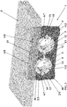
- the invention then relates, more particularly, to a holding device 1 designed to maintain at least one electrically conductive pipe (more particularly of a plurality of electrically conductive pipes and / or that comprises a pipe) on an electrically conductive S structure (more particularly constituted by a metal wall), this while ensuring an electrical connection between such a structure S electric conductor and at least one such electric conductive pipe.
- a holding device 1 designed to maintain at least one electrically conductive pipe (more particularly of a plurality of electrically conductive pipes and / or that comprises a pipe) on an electrically conductive S structure (more particularly constituted by a metal wall), this while ensuring an electrical connection between such a structure S electric conductor and at least one such electric conductive pipe.
- This holding device 1 comprises a flange 2 configured to receive at least one such pipe or a plurality of pipes, which comprises a pipe.
- This flange 2 comprises, on the one hand, a fastening half-flange 3 configured to be fixed on the structure S, this by means of fixing means and, on the other hand, a holding half-flange 4, complementary to this half-fastening flange 3, and configured to be assembled with this half-fastening flange 3, this by means of assembly means.
- These half-flanges (3; 4) each comprise a rigid body (30; 40), more particularly made of an electrically non-conductive material, in particular a plastic and / or composite material.
- these half-flanges (3; 4) each comprise at least one receiving means (31; 41) for receiving, as the case may be, fastening means for fixing the holding device 1 on the structure S and / or assembly means for assembling these two half-flanges (3; 4).
- the fixing half-flange 3 (more particularly the rigid body 30 of this half-attachment flange 3) comprises at least one receiving means 31 each adopting the shape of a through orifice.
- the holding half-flange 4 (more particularly the rigid body 40 of this holding half-flange 4) comprises at least one receiving means 41, each adopting the shape of a through orifice, and each located in the extension of the through a receiving means 31 of the fixing half-flange 3.
- the fastening means may be constituted by at least one fastening screw, passing through the orifices passing through receiving means (31; 41) of the half-flanges (3; 4) and defining, advantageously, means for assembling these half-flanges (3; 4), more particularly designed to perform the assembly of these half-flanges (3; 4) under the effect of the fixing of the holding device 1 on the structure S.
- These half-flanges (3; 4) each have, opposite the other half-flange (4; 3), on the one hand, at least one recess (32; 42), each configured to receiving a pipe, each arranged opposite another recess (42; 32) of the other half-flange (4; 3), and each completing such another recess (42; 32) to form a housing 5 for receiving the pipe or one of the pipes.
- the hollow or recesses (32; 42) have a generally semicircular shape and / or have an internal radius greater than the external radius of the pipe of the pipework that it receives.
- the housing 5 have a shape corresponding substantially to the section of the pipe that receives (more particularly a circular shape) and / or have an inner radius greater than the outer radius of such a pipe.
- the holding device 1 comprises electrical connection means 6 which are configured to electrically connect the structure S and the pipe or pipes.
- These electrical connection means 6 comprise, on the one hand, at least one pad 7, each made of an electrically conductive flexible material, each filling the hollow 32 or one of the recesses 32 of the fixing half-flange 3, and each configured to electrically cooperate with the pipe or with one of the pipes and, on the other hand, at least one pusher 8, each made of an electrically conductive material, each configured to electrically cooperate with the structure S as well as with the pad 7 or one of the pads 7 of the half-flange of fixing 3, each mobile moving between a deployed position outside the half-fastening flange 3 and a retracted position inside this half-fastening flange 3.
- these electrical connection means 6 comprise at least one pad 7 made of a flexible electrically conductive material.
- This or these pads 7 are, then, made of a flexible material which allows, advantageously and under the effect of the action of a pusher 8, to deform such a pad 7 and to bring the pad 7 in contact with the pipe or one of the pipes.
- This or these pads 7 are preferably made of a compressible material.
- This characteristic advantageously makes it possible, on the one hand, to guarantee an effective and lasting maintenance of such a pipe within the holding device 1 and, on the other hand, a displacement of such a pipe with respect to this device of maintenance 1.
- This characteristic also makes it possible, advantageously and under the effect of a pusher 8, to guarantee an efficient and lasting electrical connection between such a pad 7 and a pipe.
- this or these pads 7 are made of silicone.
- such a bush 7 has, on the one hand, an outer face 70, oriented towards a recess 32 of the rigid body 30 of the fixing half-flange 3, and in contact with the surface of such a hollow 32 (more particularly filling this surface) and, on the other hand, an inner face 71, opposite to the outer face 70, intended to be oriented in the direction of a pipe, and intended to cooperate with a such pipe.
- the electrical connection means 6 also comprise at least one pusher 8, each made of an electrically conductive material.
- this or these pushers 8 are preferably made of a rigid material and / or metal, including aluminum, steel or titanium.
- a particular embodiment is that such a pusher 8 comprises a surface treatment designed, on the one hand, to allow electrical conduction and, on the other hand, to prevent the creation of a galvanic couple between such a pusher 8 and the structure S.
- Such a surface treatment may be constituted by a coating, which comprises such a pusher 8, and which is constituted by an electrically conductive material, for example a conductive silicone.
- such a pusher 8 is movable in displacement between a deployed position outside the half-attachment flange 3 ( figures 1 and 2 ) and a retracted position inside this half-fastening flange 3 ( figures 3 and 4 ).
- this half-fastening flange 3 (more particularly the rigid body 30 of this half-fastening flange 3) has an attachment face 33, intended to be oriented in the direction of the structure S, or even to cooperate with this structure S (more particularly in the fixing position of the holding device 1 on this structure S), and with respect to which or the pushers 8 extend projecting, this in the deployed position ( figures 1 and 2 ).
- this half-fixing flange 3 comprises at least one through orifice 34, each extending from this fastening surface 33 and up to the hollow 32 or to one of the recesses 32 of this half-fixing flange 3, and each receiving the pusher 8 or one of the pushers 8 movable in translation within such a through hole 34.
- such a through hole 34 passes through, more particularly, the rigid body 30 of this half-attachment flange 3 while such a pusher 8 is movable in translation within such an orifice passing through 34, this between said deployed position ( figures 1 and 2 ) and the retracted position ( figures 3 and 4 ) of such a pusher 8.
- the half-fastening flange 3 comprises at least one cradle 9, each made of a rigid material, each of which partially lining the inner face 71 of the pad 7 or one of the pads 7 of this half-attachment flange 3, each configured to cooperate with the pipe or with one of the pipes and to be interposed between such a pad 7 and such a pipe.
- such a cradle 9 partially covers only the inner face of the pad 7 or one of the pads 7 of the half-fastening flange 3.
- such a cradle 9 covers only a portion of the inner face 71 of such a pad 7 advantageously allows such a pad 7 to extend through such a cradle 9 and to be in direct contact with the cradle 9. a pipe or with one of the pipes (this via its inner face 71).
- the cradle or cradles 9 each comprise a through opening 90 towards which the pusher 8 or one of the pushers 8 is oriented and is movable in displacement.
- Such a through opening 90 is provided in a median portion of the cradle 9, more particularly in a median portion of the width of this cradle 9, this facing a middle portion of the pad 7, plus particularly in a median portion of the width of such a pad 7.
- This characteristic makes it possible, advantageously and to make an electrical connection between such a bush 7 and a pipe, to remove the anticorrosion protection coating of such a pipe, this in a particularly localized manner and a place, located inside the half-fixing flange 3, and protected vis-à-vis the attacks of the external environment (humid and / or corrosive atmosphere) of the holding device 1.
- such a cradle 9 is configured to cooperate with the pipe or with one of the pipes.
- such a cradle 9 is configured to cooperate in an intimate manner and through most (or all) of the surface of the inner face of this cradle 9 oriented in the direction of a such pipe.
- such a cradle 9 has a shape (more particularly the shape of a semicircle) and / or dimensions (more particularly an internal radius) adjusted to those of such a pipe.
- such a cradle 9 has, then, an inner radius corresponding to the outer radius of such a pipe.
- the cradle or cradles 9 of the half-attachment flange 3 each comprise, laterally and on either side of the pad 7 or one of the pads 7 of the fixing half-flange 3 , a skirt 10 covering at least a portion of the flank 72 of this or these pads 7 of this half-fastening flange 3.
- This characteristic advantageously makes it possible to prevent the penetration of polluting substances between such a pad 7 and such a cradle 9, despite a displacement of a pipe which could tend to generate a gap between such a pad 7 and such a cradle 9 .
- such a cradle 9 that includes the fixing half-flange 3 may be made of an electrically conductive material.
- a cradle 9 is made of a non-conductive electrical material, more particularly an insulating material.
- the holding half-flange 4 comprises at least one bearing 11, each made of a flexible material, each filling the recess 42 or one of the recesses 42 of this holding half-flange 4 and each arranged opposite the pad 7 or one of the pads 7 of the fixing half-flange 3.
- This or these pads 11 of the holding half-flange 4 are preferably made of a compressible material. This characteristic makes it possible, again and advantageously, on the one hand, to guarantee an efficient and lasting maintenance of such a pipe within the holding device 1 and, on the other hand, a displacement of such a pipe with respect to this holding device 1.
- this or these pads 11 of the holding half-flange 4 are, again, made of silicone.
- Such a bush 11 has, on the one hand, an outer face 110, oriented towards a hollow 42 of the rigid body 40 of the holding half-flange 4, and in contact with the surface of such a hollow 42 (more particularly filling this surface) and, secondly, an inner face 111, opposite the outer face 110, and intended to be oriented towards a pipe.
- the pad 11 (or one of the pads 11) of the holding half-flange 4 and the pad 7 (or one of the pads 11) of the fixing half-flange 3 are arranged within the device 1, so as to substantially form a ring-shaped element.
- the half-support flange 4 comprises at least one cradle 12, each made of a rigid material, each lining the inner face 111 of the pad 11 or one of the pads 11 of this half-holding flange 4, and each configured to cooperate with the pipe or with one of the pipes and to be interposed between such a bearing 11 and such a pipe.
- such a cradle 12 covers the inner face of the pad 11 or one of the pads 11 of the holding half-flange 4. According to a preferred embodiment, such a cradle 12 completely encloses the inner face of such a cradle pad 11.
- such a cradle 12 is configured to cooperate with the pipe or with one of the pipes.
- such a cradle 12 is, again, configured to cooperate intimately and through most (or all) of the surface of the inner face of this cradle 12 oriented in direction of such a pipe.
- such a cradle 12 has a shape (more particularly the shape of a semicircle) and / or dimensions (more particularly an internal radius) adjusted to those of such a pipe.
- such a cradle 12 has, then, an inner radius corresponding to the outer radius of such a pipe.
- the cradle or cradles 12 of the holding half-flange 4 each comprise, laterally and on either side of the pad 11 or one of the pads 11 of the holding half-flange 4 , a skirt 13 covering at least a portion of the sidewall 112 of this or these pads 11 of this half-holding flange 4.
- This characteristic allows, again and advantageously, to prevent pollutant penetration between such a pad 11 and such a cradle 12, this despite a displacement of a pipe which could tend to generate a gap between such a pad 11 and such a cradle 12.
- Such a cradle 12 that includes the holding half-flange 4 may be made of an electrically conductive material or (and preferably) a non-conductive electrical material (more particularly an insulating material).
- the cradle 12 (or one of the cradles 12) of the holding half-flange 4 and the cradle 9 (or one of the cradles 9) of the fixing half-flange 3 are arranged within of the holding device 1, so as to substantially form a ring-shaped element.
- Such an element is surrounded by the annular element formed by the pad 7 (or one of the pads 7) of the half-flange 3 and by the pad 11 (or one of the pads 11) of the holding half-flange 4.
- such an element surrounds the pipe or one of the pipes of the pipe.
Landscapes
- Engineering & Computer Science (AREA)
- General Engineering & Computer Science (AREA)
- Mechanical Engineering (AREA)
- Supports For Pipes And Cables (AREA)
Applications Claiming Priority (1)
| Application Number | Priority Date | Filing Date | Title |
|---|---|---|---|
| FR1754430A FR3066648B1 (fr) | 2017-05-19 | 2017-05-19 | Dispositif de maintien d'au moins un tuyau conducteur electrique sur une structure conductrice electrique |
Publications (2)
| Publication Number | Publication Date |
|---|---|
| EP3404773A1 true EP3404773A1 (de) | 2018-11-21 |
| EP3404773B1 EP3404773B1 (de) | 2020-08-19 |
Family
ID=59409513
Family Applications (1)
| Application Number | Title | Priority Date | Filing Date |
|---|---|---|---|
| EP18172960.9A Active EP3404773B1 (de) | 2017-05-19 | 2018-05-17 | Haltevorrichtung mindestens eines elektrisch leitenden rohrs auf einer elektrisch leitfähigen struktur |
Country Status (3)
| Country | Link |
|---|---|
| US (1) | US10348001B2 (de) |
| EP (1) | EP3404773B1 (de) |
| FR (1) | FR3066648B1 (de) |
Families Citing this family (1)
| Publication number | Priority date | Publication date | Assignee | Title |
|---|---|---|---|---|
| US10800540B2 (en) * | 2017-08-03 | 2020-10-13 | The Boeing Company | Transport element clamp system |
Citations (5)
| Publication number | Priority date | Publication date | Assignee | Title |
|---|---|---|---|---|
| US2417260A (en) * | 1942-08-18 | 1947-03-11 | Adel Prec Products Corp | Sectional support for conduits |
| FR2260199A1 (de) * | 1974-02-05 | 1975-08-29 | Elhyco Ag | |
| EP0139980A2 (de) * | 1983-10-18 | 1985-05-08 | Siemens Nixdorf Informationssysteme Aktiengesellschaft | Kabelschelle |
| WO2011053573A1 (en) * | 2009-10-30 | 2011-05-05 | Illinois Tool Works Inc. | Saddle clamp having electrical bonding character |
| US20150102600A1 (en) * | 2013-10-11 | 2015-04-16 | Nicholas Clancy Schooley | Latching mechanisms for clamshell type couplers |
Family Cites Families (8)
| Publication number | Priority date | Publication date | Assignee | Title |
|---|---|---|---|---|
| US3986323A (en) | 1973-12-05 | 1976-10-19 | Aidlin Automation Incorporated | Apparatus for guiding and positioning closures on containers |
| US5261633A (en) * | 1992-12-17 | 1993-11-16 | Mastro Ronald J | Pipe support system |
| US6892990B2 (en) * | 2002-04-02 | 2005-05-17 | Preformed Line Products Company | Modular cable support apparatus, method, and system |
| US6840782B1 (en) * | 2004-02-26 | 2005-01-11 | Aaron M. Borden | Dual-sectioned grounding bushing assembly |
| US20050248098A1 (en) * | 2004-04-27 | 2005-11-10 | Sisk David E | Gasket for a coupler upon a rail car, tank trailer, or related means |
| US7770848B2 (en) * | 2007-11-29 | 2010-08-10 | The Boeing Company | Clamp for securing an object to a structure |
| JP5737903B2 (ja) * | 2010-10-26 | 2015-06-17 | 三菱重工業株式会社 | 航空機用配管支持構造 |
| DE102012216236A1 (de) * | 2012-09-13 | 2014-03-13 | Robert Bosch Gmbh | Halter zur Befestigung eines rohrförmigen Bauteils an einer Anbaustruktur |
-
2017
- 2017-05-19 FR FR1754430A patent/FR3066648B1/fr not_active Expired - Fee Related
-
2018
- 2018-04-19 US US15/957,846 patent/US10348001B2/en active Active
- 2018-05-17 EP EP18172960.9A patent/EP3404773B1/de active Active
Patent Citations (5)
| Publication number | Priority date | Publication date | Assignee | Title |
|---|---|---|---|---|
| US2417260A (en) * | 1942-08-18 | 1947-03-11 | Adel Prec Products Corp | Sectional support for conduits |
| FR2260199A1 (de) * | 1974-02-05 | 1975-08-29 | Elhyco Ag | |
| EP0139980A2 (de) * | 1983-10-18 | 1985-05-08 | Siemens Nixdorf Informationssysteme Aktiengesellschaft | Kabelschelle |
| WO2011053573A1 (en) * | 2009-10-30 | 2011-05-05 | Illinois Tool Works Inc. | Saddle clamp having electrical bonding character |
| US20150102600A1 (en) * | 2013-10-11 | 2015-04-16 | Nicholas Clancy Schooley | Latching mechanisms for clamshell type couplers |
Also Published As
| Publication number | Publication date |
|---|---|
| US10348001B2 (en) | 2019-07-09 |
| EP3404773B1 (de) | 2020-08-19 |
| US20180337465A1 (en) | 2018-11-22 |
| FR3066648A1 (fr) | 2018-11-23 |
| FR3066648B1 (fr) | 2019-06-14 |
Similar Documents
| Publication | Publication Date | Title |
|---|---|---|
| EP2273619B1 (de) | Gebogener koaxialer Anschuss und sein Zusammenbauverfahren | |
| WO2000078238A1 (fr) | Dispositif anti-recul pour implant orthopedique | |
| EP0464767A1 (de) | Aus zwei über ein Gelenk und elektrisch verbundenen Elementen bestehendes Gerät | |
| FR3035950A1 (fr) | Collier de raccordement et dispositif de raccordement de conduits comprenant un tel collier de raccordement | |
| FR2916909A1 (fr) | Dispositif de protection des elements emboitables d'un connecteur | |
| EP3323170B1 (de) | Frei verschiebbare elektrische verbindungsvorrichtung mit schutz gegen schäden durch fremdkörper | |
| FR2974613A1 (fr) | Dispositif d'accouplement pour relier de maniere liberable deux tubes. | |
| FR3066648B1 (fr) | Dispositif de maintien d'au moins un tuyau conducteur electrique sur une structure conductrice electrique | |
| FR2973955A1 (fr) | Ensemble de connexion avec insert de maintien | |
| EP3250777B1 (de) | Bohrlochstimulationswerkzeug mit gelenkverbindung | |
| CH691276A5 (fr) | Charnière élastique. | |
| EP3075614B1 (de) | Vereinfachter hydraulischer anschluss für ein wischersystem einer fahrzeugscheibe | |
| WO2013156393A1 (fr) | Système de connexion monovoie rapide | |
| FR2946468A1 (fr) | Dispositif de liaison entre un connecteur electrique et un cable electrique coaxial blinde et connecteur electrique correspondant | |
| FR2873237A1 (fr) | Ensemble connecteur auto-obturant | |
| WO2015071172A1 (fr) | Connecteur electrique a reprise de blindage | |
| FR3045700B1 (fr) | Dispositif articule en rotation dote d’un systeme de connexion electrique | |
| EP1950858B1 (de) | Befestigungsvorrichtung für Installationsgeräte mittels Krallen | |
| FR2978366A1 (fr) | Ensemble femelle de connexion d'un poste a souder | |
| EP1365484A1 (de) | Elektrische koaxiale Winkelsteckverbindungseinrichtung | |
| EP3343714B1 (de) | System zum anbringen einer fassade an einer einbaudose | |
| EP3394945B1 (de) | Stromabnehmer vorrichtung für einen kabelschirm, insbesondere für ein mittelspannungskabel | |
| EP2935909B1 (de) | Dichtungsventil für ein befestigungssystem | |
| FR2774041A1 (fr) | Dispositif de remplissage d'un reservoir de carburant de vehicule automobile comportant des moyens de mise a la masse agences sur un volet | |
| FR3027166A1 (fr) | Panneau de disjoncteurs |
Legal Events
| Date | Code | Title | Description |
|---|---|---|---|
| PUAI | Public reference made under article 153(3) epc to a published international application that has entered the european phase |
Free format text: ORIGINAL CODE: 0009012 |
|
| STAA | Information on the status of an ep patent application or granted ep patent |
Free format text: STATUS: THE APPLICATION HAS BEEN PUBLISHED |
|
| AK | Designated contracting states |
Kind code of ref document: A1 Designated state(s): AL AT BE BG CH CY CZ DE DK EE ES FI FR GB GR HR HU IE IS IT LI LT LU LV MC MK MT NL NO PL PT RO RS SE SI SK SM TR |
|
| AX | Request for extension of the european patent |
Extension state: BA ME |
|
| STAA | Information on the status of an ep patent application or granted ep patent |
Free format text: STATUS: REQUEST FOR EXAMINATION WAS MADE |
|
| 17P | Request for examination filed |
Effective date: 20190507 |
|
| RBV | Designated contracting states (corrected) |
Designated state(s): AL AT BE BG CH CY CZ DE DK EE ES FI FR GB GR HR HU IE IS IT LI LT LU LV MC MK MT NL NO PL PT RO RS SE SI SK SM TR |
|
| RIC1 | Information provided on ipc code assigned before grant |
Ipc: H01R 4/64 20060101AFI20200221BHEP Ipc: H01R 4/60 20060101ALN20200221BHEP Ipc: F16L 3/10 20060101ALI20200221BHEP Ipc: F16L 25/01 20060101ALI20200221BHEP Ipc: F16L 3/237 20060101ALN20200221BHEP Ipc: F16L 3/223 20060101ALI20200221BHEP Ipc: F16L 55/035 20060101ALI20200221BHEP |
|
| GRAP | Despatch of communication of intention to grant a patent |
Free format text: ORIGINAL CODE: EPIDOSNIGR1 |
|
| STAA | Information on the status of an ep patent application or granted ep patent |
Free format text: STATUS: GRANT OF PATENT IS INTENDED |
|
| RIC1 | Information provided on ipc code assigned before grant |
Ipc: F16L 55/035 20060101ALI20200303BHEP Ipc: H01R 4/60 20060101ALN20200303BHEP Ipc: H01R 4/64 20060101AFI20200303BHEP Ipc: F16L 3/223 20060101ALI20200303BHEP Ipc: F16L 3/10 20060101ALI20200303BHEP Ipc: F16L 25/01 20060101ALI20200303BHEP Ipc: F16L 3/237 20060101ALN20200303BHEP |
|
| INTG | Intention to grant announced |
Effective date: 20200407 |
|
| GRAJ | Information related to disapproval of communication of intention to grant by the applicant or resumption of examination proceedings by the epo deleted |
Free format text: ORIGINAL CODE: EPIDOSDIGR1 |
|
| GRAP | Despatch of communication of intention to grant a patent |
Free format text: ORIGINAL CODE: EPIDOSNIGR1 |
|
| INTG | Intention to grant announced |
Effective date: 20200528 |
|
| RIC1 | Information provided on ipc code assigned before grant |
Ipc: F16L 55/035 20060101ALI20200518BHEP Ipc: F16L 3/237 20060101ALN20200518BHEP Ipc: F16L 3/10 20060101ALI20200518BHEP Ipc: F16L 3/223 20060101ALI20200518BHEP Ipc: H01R 4/60 20060101ALN20200518BHEP Ipc: H01R 4/64 20060101AFI20200518BHEP Ipc: F16L 25/01 20060101ALI20200518BHEP |
|
| GRAS | Grant fee paid |
Free format text: ORIGINAL CODE: EPIDOSNIGR3 |
|
| GRAA | (expected) grant |
Free format text: ORIGINAL CODE: 0009210 |
|
| STAA | Information on the status of an ep patent application or granted ep patent |
Free format text: STATUS: THE PATENT HAS BEEN GRANTED |
|
| AK | Designated contracting states |
Kind code of ref document: B1 Designated state(s): AL AT BE BG CH CY CZ DE DK EE ES FI FR GB GR HR HU IE IS IT LI LT LU LV MC MK MT NL NO PL PT RO RS SE SI SK SM TR |
|
| REG | Reference to a national code |
Ref country code: CH Ref legal event code: EP |
|
| REG | Reference to a national code |
Ref country code: DE Ref legal event code: R096 Ref document number: 602018006988 Country of ref document: DE |
|
| REG | Reference to a national code |
Ref country code: AT Ref legal event code: REF Ref document number: 1305013 Country of ref document: AT Kind code of ref document: T Effective date: 20200915 |
|
| REG | Reference to a national code |
Ref country code: IE Ref legal event code: FG4D Free format text: LANGUAGE OF EP DOCUMENT: FRENCH |
|
| REG | Reference to a national code |
Ref country code: LT Ref legal event code: MG4D |
|
| REG | Reference to a national code |
Ref country code: NL Ref legal event code: MP Effective date: 20200819 |
|
| PG25 | Lapsed in a contracting state [announced via postgrant information from national office to epo] |
Ref country code: HR Free format text: LAPSE BECAUSE OF FAILURE TO SUBMIT A TRANSLATION OF THE DESCRIPTION OR TO PAY THE FEE WITHIN THE PRESCRIBED TIME-LIMIT Effective date: 20200819 Ref country code: LT Free format text: LAPSE BECAUSE OF FAILURE TO SUBMIT A TRANSLATION OF THE DESCRIPTION OR TO PAY THE FEE WITHIN THE PRESCRIBED TIME-LIMIT Effective date: 20200819 Ref country code: PT Free format text: LAPSE BECAUSE OF FAILURE TO SUBMIT A TRANSLATION OF THE DESCRIPTION OR TO PAY THE FEE WITHIN THE PRESCRIBED TIME-LIMIT Effective date: 20201221 Ref country code: NO Free format text: LAPSE BECAUSE OF FAILURE TO SUBMIT A TRANSLATION OF THE DESCRIPTION OR TO PAY THE FEE WITHIN THE PRESCRIBED TIME-LIMIT Effective date: 20201119 Ref country code: GR Free format text: LAPSE BECAUSE OF FAILURE TO SUBMIT A TRANSLATION OF THE DESCRIPTION OR TO PAY THE FEE WITHIN THE PRESCRIBED TIME-LIMIT Effective date: 20201120 Ref country code: BG Free format text: LAPSE BECAUSE OF FAILURE TO SUBMIT A TRANSLATION OF THE DESCRIPTION OR TO PAY THE FEE WITHIN THE PRESCRIBED TIME-LIMIT Effective date: 20201119 Ref country code: FI Free format text: LAPSE BECAUSE OF FAILURE TO SUBMIT A TRANSLATION OF THE DESCRIPTION OR TO PAY THE FEE WITHIN THE PRESCRIBED TIME-LIMIT Effective date: 20200819 Ref country code: SE Free format text: LAPSE BECAUSE OF FAILURE TO SUBMIT A TRANSLATION OF THE DESCRIPTION OR TO PAY THE FEE WITHIN THE PRESCRIBED TIME-LIMIT Effective date: 20200819 |
|
| REG | Reference to a national code |
Ref country code: AT Ref legal event code: MK05 Ref document number: 1305013 Country of ref document: AT Kind code of ref document: T Effective date: 20200819 |
|
| PG25 | Lapsed in a contracting state [announced via postgrant information from national office to epo] |
Ref country code: NL Free format text: LAPSE BECAUSE OF FAILURE TO SUBMIT A TRANSLATION OF THE DESCRIPTION OR TO PAY THE FEE WITHIN THE PRESCRIBED TIME-LIMIT Effective date: 20200819 Ref country code: LV Free format text: LAPSE BECAUSE OF FAILURE TO SUBMIT A TRANSLATION OF THE DESCRIPTION OR TO PAY THE FEE WITHIN THE PRESCRIBED TIME-LIMIT Effective date: 20200819 Ref country code: PL Free format text: LAPSE BECAUSE OF FAILURE TO SUBMIT A TRANSLATION OF THE DESCRIPTION OR TO PAY THE FEE WITHIN THE PRESCRIBED TIME-LIMIT Effective date: 20200819 Ref country code: RS Free format text: LAPSE BECAUSE OF FAILURE TO SUBMIT A TRANSLATION OF THE DESCRIPTION OR TO PAY THE FEE WITHIN THE PRESCRIBED TIME-LIMIT Effective date: 20200819 Ref country code: IS Free format text: LAPSE BECAUSE OF FAILURE TO SUBMIT A TRANSLATION OF THE DESCRIPTION OR TO PAY THE FEE WITHIN THE PRESCRIBED TIME-LIMIT Effective date: 20201219 |
|
| PG25 | Lapsed in a contracting state [announced via postgrant information from national office to epo] |
Ref country code: CZ Free format text: LAPSE BECAUSE OF FAILURE TO SUBMIT A TRANSLATION OF THE DESCRIPTION OR TO PAY THE FEE WITHIN THE PRESCRIBED TIME-LIMIT Effective date: 20200819 Ref country code: DK Free format text: LAPSE BECAUSE OF FAILURE TO SUBMIT A TRANSLATION OF THE DESCRIPTION OR TO PAY THE FEE WITHIN THE PRESCRIBED TIME-LIMIT Effective date: 20200819 Ref country code: RO Free format text: LAPSE BECAUSE OF FAILURE TO SUBMIT A TRANSLATION OF THE DESCRIPTION OR TO PAY THE FEE WITHIN THE PRESCRIBED TIME-LIMIT Effective date: 20200819 Ref country code: EE Free format text: LAPSE BECAUSE OF FAILURE TO SUBMIT A TRANSLATION OF THE DESCRIPTION OR TO PAY THE FEE WITHIN THE PRESCRIBED TIME-LIMIT Effective date: 20200819 Ref country code: SM Free format text: LAPSE BECAUSE OF FAILURE TO SUBMIT A TRANSLATION OF THE DESCRIPTION OR TO PAY THE FEE WITHIN THE PRESCRIBED TIME-LIMIT Effective date: 20200819 |
|
| REG | Reference to a national code |
Ref country code: DE Ref legal event code: R097 Ref document number: 602018006988 Country of ref document: DE |
|
| PG25 | Lapsed in a contracting state [announced via postgrant information from national office to epo] |
Ref country code: ES Free format text: LAPSE BECAUSE OF FAILURE TO SUBMIT A TRANSLATION OF THE DESCRIPTION OR TO PAY THE FEE WITHIN THE PRESCRIBED TIME-LIMIT Effective date: 20200819 Ref country code: AT Free format text: LAPSE BECAUSE OF FAILURE TO SUBMIT A TRANSLATION OF THE DESCRIPTION OR TO PAY THE FEE WITHIN THE PRESCRIBED TIME-LIMIT Effective date: 20200819 Ref country code: AL Free format text: LAPSE BECAUSE OF FAILURE TO SUBMIT A TRANSLATION OF THE DESCRIPTION OR TO PAY THE FEE WITHIN THE PRESCRIBED TIME-LIMIT Effective date: 20200819 |
|
| PLBE | No opposition filed within time limit |
Free format text: ORIGINAL CODE: 0009261 |
|
| STAA | Information on the status of an ep patent application or granted ep patent |
Free format text: STATUS: NO OPPOSITION FILED WITHIN TIME LIMIT |
|
| PG25 | Lapsed in a contracting state [announced via postgrant information from national office to epo] |
Ref country code: SK Free format text: LAPSE BECAUSE OF FAILURE TO SUBMIT A TRANSLATION OF THE DESCRIPTION OR TO PAY THE FEE WITHIN THE PRESCRIBED TIME-LIMIT Effective date: 20200819 |
|
| 26N | No opposition filed |
Effective date: 20210520 |
|
| PG25 | Lapsed in a contracting state [announced via postgrant information from national office to epo] |
Ref country code: IT Free format text: LAPSE BECAUSE OF FAILURE TO SUBMIT A TRANSLATION OF THE DESCRIPTION OR TO PAY THE FEE WITHIN THE PRESCRIBED TIME-LIMIT Effective date: 20200819 |
|
| PG25 | Lapsed in a contracting state [announced via postgrant information from national office to epo] |
Ref country code: SI Free format text: LAPSE BECAUSE OF FAILURE TO SUBMIT A TRANSLATION OF THE DESCRIPTION OR TO PAY THE FEE WITHIN THE PRESCRIBED TIME-LIMIT Effective date: 20200819 |
|
| REG | Reference to a national code |
Ref country code: CH Ref legal event code: PL |
|
| PG25 | Lapsed in a contracting state [announced via postgrant information from national office to epo] |
Ref country code: CH Free format text: LAPSE BECAUSE OF NON-PAYMENT OF DUE FEES Effective date: 20210531 Ref country code: LU Free format text: LAPSE BECAUSE OF NON-PAYMENT OF DUE FEES Effective date: 20210517 Ref country code: MC Free format text: LAPSE BECAUSE OF FAILURE TO SUBMIT A TRANSLATION OF THE DESCRIPTION OR TO PAY THE FEE WITHIN THE PRESCRIBED TIME-LIMIT Effective date: 20200819 Ref country code: LI Free format text: LAPSE BECAUSE OF NON-PAYMENT OF DUE FEES Effective date: 20210531 |
|
| REG | Reference to a national code |
Ref country code: BE Ref legal event code: MM Effective date: 20210531 |
|
| PG25 | Lapsed in a contracting state [announced via postgrant information from national office to epo] |
Ref country code: IE Free format text: LAPSE BECAUSE OF NON-PAYMENT OF DUE FEES Effective date: 20210517 |
|
| PG25 | Lapsed in a contracting state [announced via postgrant information from national office to epo] |
Ref country code: BE Free format text: LAPSE BECAUSE OF NON-PAYMENT OF DUE FEES Effective date: 20210531 |
|
| PG25 | Lapsed in a contracting state [announced via postgrant information from national office to epo] |
Ref country code: CY Free format text: LAPSE BECAUSE OF FAILURE TO SUBMIT A TRANSLATION OF THE DESCRIPTION OR TO PAY THE FEE WITHIN THE PRESCRIBED TIME-LIMIT Effective date: 20200819 |
|
| P01 | Opt-out of the competence of the unified patent court (upc) registered |
Effective date: 20230529 |
|
| PG25 | Lapsed in a contracting state [announced via postgrant information from national office to epo] |
Ref country code: HU Free format text: LAPSE BECAUSE OF FAILURE TO SUBMIT A TRANSLATION OF THE DESCRIPTION OR TO PAY THE FEE WITHIN THE PRESCRIBED TIME-LIMIT; INVALID AB INITIO Effective date: 20180517 |
|
| PG25 | Lapsed in a contracting state [announced via postgrant information from national office to epo] |
Ref country code: MK Free format text: LAPSE BECAUSE OF FAILURE TO SUBMIT A TRANSLATION OF THE DESCRIPTION OR TO PAY THE FEE WITHIN THE PRESCRIBED TIME-LIMIT Effective date: 20200819 |
|
| PG25 | Lapsed in a contracting state [announced via postgrant information from national office to epo] |
Ref country code: TR Free format text: LAPSE BECAUSE OF FAILURE TO SUBMIT A TRANSLATION OF THE DESCRIPTION OR TO PAY THE FEE WITHIN THE PRESCRIBED TIME-LIMIT Effective date: 20200819 |
|
| PG25 | Lapsed in a contracting state [announced via postgrant information from national office to epo] |
Ref country code: MT Free format text: LAPSE BECAUSE OF FAILURE TO SUBMIT A TRANSLATION OF THE DESCRIPTION OR TO PAY THE FEE WITHIN THE PRESCRIBED TIME-LIMIT Effective date: 20200819 |
|
| PGFP | Annual fee paid to national office [announced via postgrant information from national office to epo] |
Ref country code: DE Payment date: 20250513 Year of fee payment: 8 |
|
| PGFP | Annual fee paid to national office [announced via postgrant information from national office to epo] |
Ref country code: GB Payment date: 20250521 Year of fee payment: 8 |
|
| PGFP | Annual fee paid to national office [announced via postgrant information from national office to epo] |
Ref country code: FR Payment date: 20260316 Year of fee payment: 9 |