EP3404794A1 - Zellenausgleichssystem und steuerungsverfahren - Google Patents
Zellenausgleichssystem und steuerungsverfahren Download PDFInfo
- Publication number
- EP3404794A1 EP3404794A1 EP17862547.1A EP17862547A EP3404794A1 EP 3404794 A1 EP3404794 A1 EP 3404794A1 EP 17862547 A EP17862547 A EP 17862547A EP 3404794 A1 EP3404794 A1 EP 3404794A1
- Authority
- EP
- European Patent Office
- Prior art keywords
- cell
- voltage
- cell balancing
- charging
- battery
- Prior art date
- Legal status (The legal status is an assumption and is not a legal conclusion. Google has not performed a legal analysis and makes no representation as to the accuracy of the status listed.)
- Pending
Links
Images

Classifications
-
- H—ELECTRICITY
- H01—ELECTRIC ELEMENTS
- H01M—PROCESSES OR MEANS, e.g. BATTERIES, FOR THE DIRECT CONVERSION OF CHEMICAL ENERGY INTO ELECTRICAL ENERGY
- H01M10/00—Secondary cells; Manufacture thereof
- H01M10/42—Methods or arrangements for servicing or maintenance of secondary cells or secondary half-cells
- H01M10/44—Methods for charging or discharging
-
- H—ELECTRICITY
- H01—ELECTRIC ELEMENTS
- H01M—PROCESSES OR MEANS, e.g. BATTERIES, FOR THE DIRECT CONVERSION OF CHEMICAL ENERGY INTO ELECTRICAL ENERGY
- H01M10/00—Secondary cells; Manufacture thereof
- H01M10/42—Methods or arrangements for servicing or maintenance of secondary cells or secondary half-cells
- H01M10/4207—Methods or arrangements for servicing or maintenance of secondary cells or secondary half-cells for several batteries or cells simultaneously or sequentially
-
- H—ELECTRICITY
- H01—ELECTRIC ELEMENTS
- H01M—PROCESSES OR MEANS, e.g. BATTERIES, FOR THE DIRECT CONVERSION OF CHEMICAL ENERGY INTO ELECTRICAL ENERGY
- H01M10/00—Secondary cells; Manufacture thereof
- H01M10/42—Methods or arrangements for servicing or maintenance of secondary cells or secondary half-cells
- H01M10/44—Methods for charging or discharging
- H01M10/441—Methods for charging or discharging for several batteries or cells simultaneously or sequentially
-
- H—ELECTRICITY
- H02—GENERATION; CONVERSION OR DISTRIBUTION OF ELECTRIC POWER
- H02J—ELECTRIC POWER NETWORKS; CIRCUIT ARRANGEMENTS OR SYSTEMS FOR SUPPLYING OR DISTRIBUTING ELECTRIC POWER; SYSTEMS FOR STORING ELECTRIC ENERGY
- H02J7/00—Circuit arrangements for charging or discharging batteries or for supplying loads from batteries
- H02J7/02—Circuit arrangements for charging or discharging batteries or for supplying loads from batteries for charging batteries from AC mains by converters
-
- H—ELECTRICITY
- H02—GENERATION; CONVERSION OR DISTRIBUTION OF ELECTRIC POWER
- H02J—ELECTRIC POWER NETWORKS; CIRCUIT ARRANGEMENTS OR SYSTEMS FOR SUPPLYING OR DISTRIBUTING ELECTRIC POWER; SYSTEMS FOR STORING ELECTRIC ENERGY
- H02J7/00—Circuit arrangements for charging or discharging batteries or for supplying loads from batteries
- H02J7/40—Circuit arrangements for charging or discharging batteries or for supplying loads from batteries characterised by the exchange of charge or discharge related data
- H02J7/443—Circuit arrangements for charging or discharging batteries or for supplying loads from batteries characterised by the exchange of charge or discharge related data using passive battery identification means, e.g. resistors or capacitors
- H02J7/445—Circuit arrangements for charging or discharging batteries or for supplying loads from batteries characterised by the exchange of charge or discharge related data using passive battery identification means, e.g. resistors or capacitors in response to measured battery parameters, e.g. voltage, current or temperature profile
-
- H—ELECTRICITY
- H02—GENERATION; CONVERSION OR DISTRIBUTION OF ELECTRIC POWER
- H02J—ELECTRIC POWER NETWORKS; CIRCUIT ARRANGEMENTS OR SYSTEMS FOR SUPPLYING OR DISTRIBUTING ELECTRIC POWER; SYSTEMS FOR STORING ELECTRIC ENERGY
- H02J7/00—Circuit arrangements for charging or discharging batteries or for supplying loads from batteries
- H02J7/50—Circuit arrangements for charging or discharging batteries or for supplying loads from batteries acting upon multiple batteries simultaneously or sequentially
- H02J7/52—Circuit arrangements for charging or discharging batteries or for supplying loads from batteries acting upon multiple batteries simultaneously or sequentially for charge balancing, e.g. equalisation of charge between batteries
-
- H—ELECTRICITY
- H02—GENERATION; CONVERSION OR DISTRIBUTION OF ELECTRIC POWER
- H02J—ELECTRIC POWER NETWORKS; CIRCUIT ARRANGEMENTS OR SYSTEMS FOR SUPPLYING OR DISTRIBUTING ELECTRIC POWER; SYSTEMS FOR STORING ELECTRIC ENERGY
- H02J7/00—Circuit arrangements for charging or discharging batteries or for supplying loads from batteries
- H02J7/50—Circuit arrangements for charging or discharging batteries or for supplying loads from batteries acting upon multiple batteries simultaneously or sequentially
- H02J7/52—Circuit arrangements for charging or discharging batteries or for supplying loads from batteries acting upon multiple batteries simultaneously or sequentially for charge balancing, e.g. equalisation of charge between batteries
- H02J7/56—Active balancing, e.g. using capacitor-based, inductor-based or DC-DC converters
-
- H—ELECTRICITY
- H02—GENERATION; CONVERSION OR DISTRIBUTION OF ELECTRIC POWER
- H02J—ELECTRIC POWER NETWORKS; CIRCUIT ARRANGEMENTS OR SYSTEMS FOR SUPPLYING OR DISTRIBUTING ELECTRIC POWER; SYSTEMS FOR STORING ELECTRIC ENERGY
- H02J7/00—Circuit arrangements for charging or discharging batteries or for supplying loads from batteries
- H02J7/80—Circuit arrangements for charging or discharging batteries or for supplying loads from batteries including monitoring or indicating arrangements
- H02J7/82—Control of state of charge [SOC]
-
- H—ELECTRICITY
- H01—ELECTRIC ELEMENTS
- H01M—PROCESSES OR MEANS, e.g. BATTERIES, FOR THE DIRECT CONVERSION OF CHEMICAL ENERGY INTO ELECTRICAL ENERGY
- H01M10/00—Secondary cells; Manufacture thereof
- H01M10/42—Methods or arrangements for servicing or maintenance of secondary cells or secondary half-cells
- H01M10/425—Structural combination with electronic components, e.g. electronic circuits integrated to the outside of the casing
- H01M2010/4271—Battery management systems including electronic circuits, e.g. control of current or voltage to keep battery in healthy state, cell balancing
-
- H—ELECTRICITY
- H02—GENERATION; CONVERSION OR DISTRIBUTION OF ELECTRIC POWER
- H02J—ELECTRIC POWER NETWORKS; CIRCUIT ARRANGEMENTS OR SYSTEMS FOR SUPPLYING OR DISTRIBUTING ELECTRIC POWER; SYSTEMS FOR STORING ELECTRIC ENERGY
- H02J2207/00—Details of circuit arrangements for charging or discharging batteries or supplying loads from batteries
- H02J2207/10—Control circuit supply, e.g. means for supplying power to the control circuit
-
- H—ELECTRICITY
- H02—GENERATION; CONVERSION OR DISTRIBUTION OF ELECTRIC POWER
- H02J—ELECTRIC POWER NETWORKS; CIRCUIT ARRANGEMENTS OR SYSTEMS FOR SUPPLYING OR DISTRIBUTING ELECTRIC POWER; SYSTEMS FOR STORING ELECTRIC ENERGY
- H02J2207/00—Details of circuit arrangements for charging or discharging batteries or supplying loads from batteries
- H02J2207/40—Details of circuit arrangements for charging or discharging batteries or supplying loads from batteries adapted for charging from various sources, e.g. AC, DC or multivoltage
-
- Y—GENERAL TAGGING OF NEW TECHNOLOGICAL DEVELOPMENTS; GENERAL TAGGING OF CROSS-SECTIONAL TECHNOLOGIES SPANNING OVER SEVERAL SECTIONS OF THE IPC; TECHNICAL SUBJECTS COVERED BY FORMER USPC CROSS-REFERENCE ART COLLECTIONS [XRACs] AND DIGESTS
- Y02—TECHNOLOGIES OR APPLICATIONS FOR MITIGATION OR ADAPTATION AGAINST CLIMATE CHANGE
- Y02B—CLIMATE CHANGE MITIGATION TECHNOLOGIES RELATED TO BUILDINGS, e.g. HOUSING, HOUSE APPLIANCES OR RELATED END-USER APPLICATIONS
- Y02B40/00—Technologies aiming at improving the efficiency of home appliances, e.g. induction cooking or efficient technologies for refrigerators, freezers or dish washers
-
- Y—GENERAL TAGGING OF NEW TECHNOLOGICAL DEVELOPMENTS; GENERAL TAGGING OF CROSS-SECTIONAL TECHNOLOGIES SPANNING OVER SEVERAL SECTIONS OF THE IPC; TECHNICAL SUBJECTS COVERED BY FORMER USPC CROSS-REFERENCE ART COLLECTIONS [XRACs] AND DIGESTS
- Y02—TECHNOLOGIES OR APPLICATIONS FOR MITIGATION OR ADAPTATION AGAINST CLIMATE CHANGE
- Y02E—REDUCTION OF GREENHOUSE GAS [GHG] EMISSIONS, RELATED TO ENERGY GENERATION, TRANSMISSION OR DISTRIBUTION
- Y02E60/00—Enabling technologies; Technologies with a potential or indirect contribution to GHG emissions mitigation
- Y02E60/10—Energy storage using batteries
Definitions
- the present invention relates to a cell balancing system and method, and more particularly, to a cell balancing system and method capable of supplying a charging voltage through two separately configured charging voltage sources and stably performing cell balancing by supplying a proper charging voltage to a corresponding cell through an individually configured switch in each cell, when the cell balancing is necessary.
- a battery such as a lithium ion cell is used as a power source for various electronic devices.
- a battery (pack) is configured from a plurality of unit cells, and for the plurality of cells, charging voltages thereof become differed due to an individual difference in dynamic state caused by a Coulombic efficiency and capacity, as operation time passes.
- this may also cause a total charge amount of the battery to be permanently limited, when at least one cell has a very higher charging voltage than other cells.
- the battery When one cell has a limiting value of the lowest charging voltage and another cell has a limiting value of the highest charging voltage, the battery may not be charged or discharged, although all other cells respectively have proper charging voltages.
- cell balancing is necessary for the battery pack, and there are typically two cell balancing schemes of a passive scheme and an active scheme.
- a voltage difference with other cells is reduced by applying a high level cell voltage across a resistor to consume the voltage as heat energy.
- the entire cells are made to have a uniform value by moving a high level cell voltage to a cell having a low level voltage by using an element for storing energy such as an inductor or capacitor.
- a time required to balance is relatively short, but the balancing is performed only in a direction of lowering the voltage of the battery. As time passes, an output of the battery is continuously reduced to shorten a charging cycle and an internal temperature of the battery pack is raised as heat energy is generated through a resistor.
- the active scheme has a relatively long charging cycle than the passive scheme due to low energy consumption, but a voltage of one cell is moved to another cell, which results in a long cell balancing time.
- the present invention provides a cell balancing system and method capable of performing rapid cell balancing without consuming a battery voltage.
- a cell balancing system includes: a battery pack configured from two or more battery cells; a battery management system (BMS) for monitoring voltages of two or more battery cells during charging of the battery pack, and commanding to perform cell balancing for a battery cell, when a corresponding battery cell has a voltage difference equal to or greater than a prescribed value with other battery cells; a charging voltage switching unit for switching a pack charging voltage, which having charged the battery pack, to a cell balancing voltage for charging the battery cell and connecting the cell balancing voltage to the battery pack according to a cell balancing command from the BMS; and a cell switching unit for individually controlling to turn on/off a provision of the cell balancing voltage to each battery cell.
- BMS battery management system
- the charging voltage switching unit may include: a pack charging voltage source for converting an input voltage provided from external power to a pack charging voltage to output the pack charging voltage; a cell balancing voltage source for converting the input voltage provided from the external power to a cell balancing voltage to output the cell balancing voltage; a microcontroller unit (MCU) for controlling to release provision of the pack charging voltage for charging the battery pack to the battery pack and to switch to the cell balancing voltage to be provided according to the cell balancing command transmitted from the BMS; a circuit switching unit for switching a circuit according to a control by the MCU to provide the input voltage from an outside to the cell balancing voltage source; and a cell balancing voltage source for receiving the input voltage through the circuit switched by the circuit switching unit to provide the cell balancing voltage to a corresponding cell.
- MCU microcontroller unit
- the charging voltage switching unit may control the circuit switching unit so as to charge the battery pack through the pack charging voltage source, when the cell balancing command is not transmitted from the BMS.
- the circuit switching unit may be configured from a plurality of switches connected with the MCU and the converter.
- Each of the cell switching unit may be configured from a first switch connected to an anode of the cell, the BMS, and the cell balancing voltage source, and a second switch connected to a cathode, the BMS and the ground.
- a cell balancing method performs balancing of two or more battery cells configuring a battery pack.
- the method includes: a battery pack charging step for performing charging of the battery pack; a cell balance checking step for checking whether cell balancing is necessary due to occurrence of voltage imbalance in a battery cell of the battery pack being in charge in the battery pack charging step; a circuit switching step for switching a circuit so as to provide the cell balancing voltage to a corresponding battery cell to connect a power supply circuit, which has been connected to the pack charging voltage source, to the cell balancing voltage source, when it is checked that the cell balancing is necessary in the cell balance checking step; and a cell switch control step for turning on a cell switch of the corresponding cell so as to provide the cell balancing voltage input through the circuit switched in the circuit switching step to a cell requiring the cell balancing.
- the cell balance checking step may include: a cell voltage measuring step for periodically measuring each voltage of the two or more battery cells; a voltage difference calculating step for calculating a voltage difference between cells by using the two or more battery cell voltages measured in the cell voltage measuring step; and a voltage difference comparing step for comparing the voltage difference between cells calculated in the voltage difference calculating step with a voltage difference in a preset prescribed range.
- the circuit switching step when the voltage difference between cells is greater than the voltage difference in the preset prescribed range, the circuit switching step may be performed.
- the switching may be performed by turning on a switch connected to the pack charging voltage source, and turning off a switch connected to the cell balancing voltage source.
- a ground terminal of the cell switching unit and a ground terminal in the charging voltage switching unit may be electrically connected.
- a switch having been connected to the cell balancing voltage source may be turned off for performing cell balancing, and a switch having been connected to the pack charging voltage source may be turned on so as to connect a battery pack charging circuit with the power supplying circuit again.
- a switch having been connected to the cell balancing voltage source may be turned off for cell balancing.
- a cell balancing system and method according to an embodiment of the present invention may have a switch formed in each cell to perform rapid and efficient cell balancing by providing a cell balancing voltage for charging a cell to a corresponding cell through the switch, when cell voltage imbalance occurs.
- first, second or the like may be used for describing various elements but does not limit the elements. Such terms are only used for distinguishing one element from other elements. For example, without departing the scope of the present invention, a first element may be referred to as a second element, and likewise, a second element may be referred to as a first element.
- the terminology used herein is not for delimiting the present invention but for describing specific embodiments. The terms of a singular form may include plural forms unless otherwise specified.
- a cell balancing system may have a switch formed in each cell to perform rapid and efficient cell balancing by receiving a cell balancing voltage through the switch and charging only the corresponding cell, when cell voltage imbalance occurs.
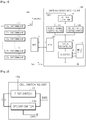
- FIG. 1 is a block diagram of a cell balancing system according to an embodiment of the present invention.
- a cell balancing system 100 includes a battery pack formed of two or more battery cells, a battery management system (BMS) 110 for commanding to perform cell balancing on a corresponding cell, when voltages of the two or more battery cells are monitored during charging of the battery pack and there is a battery cell having a voltage difference equal to or greater than a prescribed value with other battery cells, a charging voltage switching unit 120 for switching, to a cell balancing voltage, a pack charging voltage having charged the battery pack according to a cell balancing command, and connecting the cell balancing voltage to the battery pack, and a cell switching unit 130 for individually turning on/off a supply of the cell balancing voltage to the cell.
- BMS battery management system
- the charging voltage switching unit 120 includes an input unit 121 for receiving an AC input power from the outside, as a charging voltage is supplied through two voltage sources that supply different voltages, a converter 122 for converting the AC input power from the input unit 121 to DC input power so as to be able to charge the battery pack, an micro-controller unit (MCU) 123 for commanding that a voltage of the DC input power from the converter 122 is to be delivered to one of the two voltage sources, and a circuit switching unit 124 connected to one of the two voltage sources according to the command from the MCU 123 and for delivering the voltage of the DC input power to a battery.
- MCU micro-controller unit
- the two voltage sources are a pack charging voltage source 125 and the cell balancing voltage source 126, and the circuit switching unit 124 selectively applies external power input through the converter 122 to the pack charging voltage source 125 or the cell balancing voltage source 126 according to the command from the MCU 123.
- the MCU 123 commands that the input voltage from the outside is supplied to the cell balancing voltage source 126, and according to the command from the MCU 123, the circuit switching unit 124 switches to connect a circuit, which has been connected to the cell balancing voltage source 126, to the pack charging voltage source 125.
- the cell balancing voltage source 126 provides the cell balancing voltage to a corresponding cell such that cell balancing is performed.
- the charging voltage switching unit 120 charges the battery pack by connecting the input voltage provided from the external power to the pack charging voltage source 125 to provide the pack charging voltage to the battery pack.
- the converter 120 is electrically connected to the ground.
- the cells of the battery pack are connected in parallel to raise the capacity of the battery pack and have a constant voltage.
- the two voltage sources mean a pack charging voltage source 125 for providing the pack charging voltage so as to charge the battery pack, and the cell balancing voltage source 126 for providing a cell balancing voltage such that a cell, which requires cell balancing, among multiple battery cells that configure the battery pack is charged.
- pack charging voltage is set to 16.8 V as an embodiment, but is not limited thereto.
- the cell balancing voltage is set to 5 V as an embodiment, but is not limited thereto.
- the pack charging voltage source 125 and the cell balancing voltage source 126 respectively further include configurations for dropping the voltage of the DC input power to each proper output voltage.
- the pack charging voltage source 125 drops the input external power to a voltage necessary for charging the battery pack and outputs the voltage.
- the pack charging voltage source 125 may include a voltage drop circuit for receiving the external input voltage and dropping the external input voltage to the pack charging voltage.
- the cell balancing voltage source 126 drops the input external power to a voltage necessary for balancing the battery cells and outputs the voltage.
- the cell balancing voltage source 126 may include a voltage drop circuit for receiving the external input voltage and dropping the external input voltage to the cell balancing voltage.
- outputs of the pack charging voltage source 125 and the cell balancing voltage source 126 may be output to the battery pack or the plurality of battery cells through the voltage output unit 127.
- the MCU 123 is controlled by the BMS 110 of the battery pack, and the MCU 123 and the BMS 110 communicates to each other.
- the communication may be performed by means of an internal communication scheme such as I2C, SMBus, CAN, UART and SPI, and commands may be transmitted thereby.
- the BMS 110 stops provision of the pack charging voltage to the MCU 123 and transmits a command for switching the pack charging voltage to the cell balancing voltage and providing the cell balancing voltage.
- the BMS 110 transmits a command for stopping the provision of the cell balancing voltage and switching the cell balancing voltage to the pack charging voltage to provide the pack charging voltage.
- the circuit switching unit 124 is configured from a plurality of switches connected to and controlled by the MCU 123 so as to connect or disconnect the converter 122 to or from the pack charging voltage source 125 or the cell balancing voltage source 126, and switches a circuit by turning on/off the switches.
- a switch of a circuit, in which the pack charging voltage source 125 and the converter 122 are connected is turned off and a switch for connecting the cell balancing voltage source 126 with the converter 122 is turned on such that a voltage of the DC charging voltage from the converter 122 is provided.
- the cell balancing voltage is applied to the two or more battery cells by the cell balancing voltage source 126, and the pack charging voltage is applied to the battery pack by the pack charging voltage source 125, when the cell balancing is not necessary, but the battery pack is required to be charged.
- a switch element of the circuit switching unit 124 may use a Metal Oxide Field Effect Transistor (MOSFET), a Bipolar Junction Transistor (BJT), or an Insulated Gate Bipolar Transistor (IGBT), etc.
- MOSFET Metal Oxide Field Effect Transistor
- BJT Bipolar Junction Transistor
- IGBT Insulated Gate Bipolar Transistor
- the cell balancing voltage across the circuit switched by the circuit switching unit 124 is provided to a corresponding cell, which requires the cell balancing, through the cell switching unit 130.
- Detailed description about the cell switching unit 130 will be provided in relation to FIG. 2 .
- FIG. 2 is a block diagram of a cell switching unit in the cell balancing system according to an embodiment of the present invention.
- the cell switching unit 130 in the cell balancing system includes a first switch 131, a first end of which is connected to the BMS 110 and receives a signal, a second end of which is connected to a path of a voltage input from the cell balancing voltage source 126, and a third end of which is connected to an anode of the battery cell, and a second switch 132, a first end of which is connected to the BMS 110 and receives a signal, a second end of which is connected to the ground, and a third end of which is connected to a cathode of the battery cell.
- a ground terminal of the cell switching unit 130 is electrically connected to a ground terminal in the charging voltage switching unit 120.
- the cell switching unit 130 is provided in plurality so as to be allocated to each individual battery cell.
- the cell balancing system 100 receives AC input power from the outside through the input unit 121, and the received AC input power is converted to DC input power by the converter 122.
- the BMS 110 checks cell balancing and transmits a cell balancing command to the MCU 123, when the cell balancing is necessary.
- the BMS 110 outputs a cell balancing signal to the cell switching unit 130 of a cell that requires balancing.
- the MCU 123 having received a cell balancing command from the BMS 110 switches a circuit through the circuit switching unit 124 and provides a voltage of the DC input power from the converter 122 to the cell balancing voltage source 126.
- the switch connected to the pack charging voltage source 125 is turned off and the switch connected to the cell balancing voltage source 126 is turned on.
- the cell switching unit 130 having received the cell balancing signal from the BMS 110 turns on a first switch 131 and a second switch 132 to allow the cell balancing voltage input from the cell balancing voltage source 126 to be provided. At this point, the first end of the second switch 132 is connected to the ground to which the converter 122 is connected.
- the BMS 110 determines whether to perform battery pack charging again or stop charging.
- the BMS 110 When determining that the battery pack charging is necessary, the BMS 110 transmits a battery pack charging resume command to the MCU 123, and outputs a cell balancing stop signal to the cell switching unit 130.
- the MCU 130 which having received the battery pack charging resume command, controls the circuit switching unit 124 to switch a circuit, which has been connected to the cell balancing voltage source 126, to be connected to the pack charging voltage source 125 again.
- the switch connected to the cell balancing voltage source 126 is turned off and the switch connected to the pack charging voltage source 125 is turned on.
- the cell switching unit 130 having been received the cell balancing stop signal from the BMS 110 turns off the first and second switches 131 and 132. At this point, the connection of the second switch 132 to the ground is released.
- the BMS 110 transmits a battery pack charging stop command to the MCU 130, and outputs a cell balancing stop signal to the cell switching unit 130.
- the MCU 123 having received the charging stop command from the BMS 110 controls the circuit switching unit 124 to release connections with the pack charging voltage source 125 and the cell balancing voltage source 126.
- the switch connected to the cell balancing voltage source 126 in the switching unit 124 is turned off.
- the cell balancing is performed after the battery pack charging is completed.
- the BMS 110 measures a voltage of each cell of the battery pack and compares the measured cell voltage with a preset prescribed voltage.
- the BMS 110 transmits a cell balancing command to the MCU 123 and outputs a cell balancing signal to the cell switching unit 130.
- the MCU 123 controls the cell switching unit 124 to switch a circuit, which has been connected to the pack charging voltage source 125, to be connected to the cell balancing voltage source 126.
- the switch connected to the pack charging voltage source 125 is turned off and the switch connected to the cell balancing voltage source 126 is turned on.
- the circuit connected to the cell balancing voltage source 126 is provided with the voltage of the DC input power from the converter 122.
- the cell switching unit 130 having been received the cell balancing signal from the BMS 110 turns on the first and second switches 131 and 132 to allow the cell balancing voltage to be provided to a corresponding cell.
- the second switch 132 is connected to the ground to which the converter 122 is connected.
- the BMS 110 transmits a battery pack charging stop command to the MCU 130, and outputs a cell balancing stop signal to the cell switching unit 130.
- the MCU 123 having received the charging stop command from the BMS 110 controls the circuit switching unit 124 to release a circuit connection with the pack charging voltage source 125 and the cell balancing voltage source 126.
- the switching unit 124 the switch connected to the cell balancing voltage source 126 is turned off.
- the cell switching unit 130 having applied the cell balancing stop signal from the BMS 110 turns off the first and second switches 131 and 132. At this point, the connection of the second switch 132 to the ground is released.
- a cell balancing method of the present invention is a method for performing cell balancing by switching a pack charging voltage, which having been provided to a circuit, to a cell balancing voltage and controlling a switch of a corresponding cell, which requires cell balancing, to provide the cell balancing voltage to the corresponding cell, when the cell balancing is necessary at the time of charging the battery pack.
- FIG. 3 is a flowchart of a cell balancing method according to an embodiment of the present invention.
- the cell balancing method first, charges a battery pack with an input voltage provided from external power (battery pack charging step S310), and, when voltage imbalance occurs in a battery cell of the battery pack being in charge, checks whether the corresponding cell requires cell balancing (cell balance checking step S320). When it is checked that the cell balancing is necessary in the cell balance checking step S220, a circuit is switched such that the cell balancing voltage is provided to the corresponding cell and a power supply circuit, which has been connected to the pack charging voltage source 125, is connected to the cell balancing voltage source 126 (circuit switching step S330). S330).
- cell switches 131 and 132 of a cell which requires cell balancing, are turned on such that the corresponding cell is provided with the cell balancing voltage that has been input through the switched circuit in the circuit switching step S330 (cell switch control step S340). At this point, the second switch 132 is connected to the ground to which the converter 122 is connected.
- the circuit switching method in the switch switching step S330 is performed by turning off a switch for connecting the converter 122 with the pack charging voltage source 125, and turning on a switch for connecting the converter 122 with the cell balancing voltage source 126.
- the charging voltage for charging the battery pack is set to 16.8 V as an embodiment, but is not limited thereto.
- the cell balancing voltage has the voltage magnitude used in the cell and set to 5 V as an embodiment, but is not limited thereto.
- the BMS determines whether additional charging for the battery pack is necessary or charging is to be stopped on the basis of a voltage of a cell for which cell balancing is completed.
- the switch connected to the cell balancing voltage source 160 is turned off and the switch connected to the pack charging voltage source 150 is turned on, such that the circuit having been connected to perform the cell balancing is connected to the battery pack charging circuit again.
- first and second switches 131 and 132 of each battery cell having performed the cell balancing are turned off. At this point, the connection of the second switch 132 to the ground is released.
- the switch connected to the cell balancing voltage source 160 is turned off, and the first and second switches 131 and 132 of each battery cell, which has performed the cell balancing, are also turned off. At this point, the connection of the second switch 132 to the ground is released.
- FIG. 4 is a flowchart of the cell balance checking step in the cell balancing method according to an embodiment of the present invention.
- each voltage of two or more battery cells is periodically measured (cell voltage measuring step S221), and a voltage difference between cells are calculated using the two or more battery cell voltages measured in the cell voltage measuring step S221 (voltage difference calculating step S222).
- the voltage difference between cells calculated in the voltage difference calculating step S322 is compared with a voltage difference in a preset prescribed range (voltage difference comparing step S223).
- a period is arbitrarily set by a user within a range in which the interval between periods does not lower a charging efficiency of the battery pack.
- a method for calculating a voltage difference is a method for subtracting a voltage value of each cell from a maximum value among voltage values measured for each cell.
- the preset prescribed range of the voltage difference is set to a range in which efficient battery pack charging is possible with a prescribed cell balancing voltage, while a time for charging a cell, which requires cell balancing, is reduced.
- whether to perform the cell balancing is determined in real time.
- This scheme is disadvantageous in that it is necessary to measure a voltage and make determination in real time, which results in a complicated algorithm.
- the other embodiment is a method for performing the cell balancing after the battery pack charging is completed.
- the charging of the battery pack is completed using an input voltage provided from external power, and each voltage of two or more battery cells is measured.
- each of the measured two or more battery cell voltages is compared with a preset prescribed voltage to determine that cell balancing is necessary for a cell of which measured cell voltage is smaller than the preset prescribed voltage value.
- circuit switching is performed such that a circuit connected to charge an existing battery pack is switched to a circuit for performing cell balancing, and the cell switching unit 130 controls to turn on the first and second switches 131 and 132 to allow a voltage to be provided from the circuit for performing the cell balancing.
- the second switch 132 is connected to the ground to which the converter 122 is connected.
- the switch of the circuit which has been connected to the cell balancing voltage source 126 in order to perform cell balancing, is turned off, and the first and second switches 131 and 132 through which the cell balancing voltage has been provided are also turned off. At this point, the connection of the second switch 132 to the ground is released.
Landscapes
- Engineering & Computer Science (AREA)
- Power Engineering (AREA)
- Manufacturing & Machinery (AREA)
- Chemical & Material Sciences (AREA)
- Chemical Kinetics & Catalysis (AREA)
- Electrochemistry (AREA)
- General Chemical & Material Sciences (AREA)
- Charge And Discharge Circuits For Batteries Or The Like (AREA)
- Secondary Cells (AREA)
Applications Claiming Priority (2)
| Application Number | Priority Date | Filing Date | Title |
|---|---|---|---|
| KR1020160137838A KR20180044483A (ko) | 2016-10-21 | 2016-10-21 | 셀 밸런싱 시스템 및 제어방법 |
| PCT/KR2017/011448 WO2018074809A1 (ko) | 2016-10-21 | 2017-10-17 | 셀 밸런싱 시스템 및 제어방법 |
Publications (2)
| Publication Number | Publication Date |
|---|---|
| EP3404794A1 true EP3404794A1 (de) | 2018-11-21 |
| EP3404794A4 EP3404794A4 (de) | 2019-03-13 |
Family
ID=62019686
Family Applications (1)
| Application Number | Title | Priority Date | Filing Date |
|---|---|---|---|
| EP17862547.1A Pending EP3404794A4 (de) | 2016-10-21 | 2017-10-17 | Zellenausgleichssystem und steuerungsverfahren |
Country Status (6)
| Country | Link |
|---|---|
| US (1) | US10629961B2 (de) |
| EP (1) | EP3404794A4 (de) |
| JP (1) | JP6639686B2 (de) |
| KR (1) | KR20180044483A (de) |
| CN (1) | CN108604811A (de) |
| WO (1) | WO2018074809A1 (de) |
Families Citing this family (12)
| Publication number | Priority date | Publication date | Assignee | Title |
|---|---|---|---|---|
| KR102196266B1 (ko) * | 2017-04-03 | 2020-12-29 | 주식회사 엘지화학 | 원통형 배터리 셀의 방열 구조 |
| KR102202613B1 (ko) * | 2017-09-27 | 2021-01-12 | 주식회사 엘지화학 | 배터리 모듈 균등화 장치, 이를 포함하는 배터리 팩 및 자동차 |
| KR102842049B1 (ko) | 2019-06-28 | 2025-08-04 | 주식회사 엘지에너지솔루션 | 불량 배터리 셀 검출 장치 및 방법 |
| KR102876299B1 (ko) | 2019-08-20 | 2025-10-23 | 주식회사 엘지에너지솔루션 | 배터리 시스템 및 배터리 시스템의 운용 방법 |
| CN111864859B (zh) * | 2020-08-12 | 2024-05-10 | 优动能科技(深圳)有限公司 | 一种带恒流恒压充放电的锂电池组寿命延长系统及方法 |
| CN112202221B (zh) * | 2020-09-28 | 2024-06-07 | 天津津航计算技术研究所 | 基于无桥隔离型电流校正技术的电池均衡电路及方法 |
| CN112224090A (zh) * | 2020-11-19 | 2021-01-15 | 南京迅之蜂智能科技有限公司 | 一种基于can通讯带有反向充电的双电池平衡器及控制方法 |
| JP7741618B2 (ja) * | 2021-03-29 | 2025-09-18 | ダイハツ工業株式会社 | バッテリシステム |
| KR20230039565A (ko) * | 2021-09-14 | 2023-03-21 | 에이블릭 가부시키가이샤 | 셀 밸런스 회로, 셀 밸런스 장치, 충방전 제어 회로, 충방전 제어 장치 및 배터리 장치 |
| KR102539821B1 (ko) * | 2022-02-17 | 2023-06-08 | 울산대학교 산학협력단 | 재사용 배터리의 soc 임의 정렬 시스템 및 방법 |
| KR20240123071A (ko) * | 2023-02-06 | 2024-08-13 | 울산대학교 산학협력단 | 고전압 배터리의 고속 타겟 밸런싱 방법 및 시스템 |
| JP2024155004A (ja) * | 2023-04-20 | 2024-10-31 | トヨタ自動車株式会社 | 全固体電池システムおよび車両 |
Family Cites Families (34)
| Publication number | Priority date | Publication date | Assignee | Title |
|---|---|---|---|---|
| US5528122A (en) * | 1994-11-29 | 1996-06-18 | Ventron Corporation | Battery voltage equalizer circuit |
| JPH11289676A (ja) * | 1998-04-01 | 1999-10-19 | Toyo System Kk | 二次電池充放電装置用の電源装置 |
| JP2001008373A (ja) | 1999-06-17 | 2001-01-12 | Sony Corp | バッテリー装置及びバッテリーの充電方法 |
| JP3670522B2 (ja) * | 1999-07-30 | 2005-07-13 | 富士通株式会社 | バッテリパック |
| JP2002281686A (ja) * | 2001-01-12 | 2002-09-27 | Jeol Ltd | 蓄電電源の充電装置及び充電方法 |
| TW552759B (en) * | 2001-02-15 | 2003-09-11 | Seiko Instr Inc | Battery state monitoring circuit |
| US7378818B2 (en) * | 2002-11-25 | 2008-05-27 | Tiax Llc | Bidirectional power converter for balancing state of charge among series connected electrical energy storage units |
| JP3832660B2 (ja) * | 2003-10-29 | 2006-10-11 | 株式会社Nttファシリティーズ | 充電装置 |
| CN100358212C (zh) * | 2005-04-05 | 2007-12-26 | 苏州星恒电源有限公司 | 电池均衡电路 |
| JP2006320044A (ja) * | 2005-05-10 | 2006-11-24 | Ntt Data Corp | バッテリ充電器 |
| US20080218127A1 (en) | 2007-03-07 | 2008-09-11 | O2Micro Inc. | Battery management systems with controllable adapter output |
| KR100966732B1 (ko) | 2008-02-28 | 2010-06-29 | 쌍용자동차 주식회사 | 배터리 시스템의 배터리 균등 충전장치 및 그 방법 |
| JP2009247195A (ja) * | 2008-03-31 | 2009-10-22 | O2 Micro Inc | 充電電流を調節できるバッテリ管理システム |
| JP2010029050A (ja) | 2008-07-24 | 2010-02-04 | Toshiba Corp | 電池システム |
| US8350528B2 (en) * | 2009-02-04 | 2013-01-08 | Samsung Sdi Co., Ltd. | Battery pack and balancing method of battery cells |
| KR100969589B1 (ko) | 2009-03-03 | 2010-07-12 | 대호전자(주) | 급속 충전용 배터리 모듈 관리 시스템 |
| KR20110117992A (ko) | 2010-04-22 | 2011-10-28 | 장승민 | 배터리 충전 시스템 및 그것의 충전 방법 |
| CN102064580A (zh) * | 2010-12-14 | 2011-05-18 | 宁波飞驰达电子科技发展有限公司 | 串联电池组充电平衡系统及其充电平衡方法 |
| KR101256079B1 (ko) | 2010-12-28 | 2013-04-19 | 삼성에스디아이 주식회사 | 배터리 팩의 밸런싱 방법 및 밸런싱 시스템 |
| CN102569926B (zh) * | 2010-12-31 | 2015-10-14 | 欣旺达电子股份有限公司 | 汽车锂电池充电平衡方法以及平衡系统 |
| KR101241532B1 (ko) * | 2011-09-05 | 2013-03-11 | 에스케이씨앤씨 주식회사 | 충전 전압을 적응적으로 가변시키는 배터리 충전 장치 및 그의 배터리 충전 제어방법 |
| KR101377745B1 (ko) * | 2011-09-20 | 2014-03-25 | 정윤이 | 배터리 에너지 저장장치, 그리고 이의 충전 방법 |
| KR101241489B1 (ko) * | 2011-09-29 | 2013-03-11 | 에스케이씨앤씨 주식회사 | 외부 배터리 셀을 이용하여 셀 밸런싱을 수행하는 전원 공급 장치 및 그의 셀 밸런싱 방법 |
| US20130141047A1 (en) * | 2011-12-02 | 2013-06-06 | Golden Crown New Energy (Hk) Limited | Battery management system and method thereof |
| CN102522788A (zh) * | 2011-12-02 | 2012-06-27 | 苏州冠硕新能源有限公司 | 电池管理系统及采用该系统进行电池充电模式控制的方法 |
| CN102522798B (zh) * | 2011-12-30 | 2014-01-08 | 深圳桑达国际电子器件有限公司 | 一种电池组模块之间的主动均衡电路 |
| TWI452797B (zh) * | 2012-03-13 | 2014-09-11 | Univ Nat Formosa | 二次電池組充放電平衡偵測及充電裝置 |
| KR102163852B1 (ko) | 2012-09-10 | 2020-10-12 | 주식회사 실리콘웍스 | 셀 밸런싱 집적회로, 셀 밸런싱 시스템 및 셀 밸런싱 방법 |
| KR101572178B1 (ko) * | 2012-12-04 | 2015-11-26 | 주식회사 엘지화학 | 이차 전지 셀의 전압 밸런싱 장치 및 방법 |
| CN202997622U (zh) * | 2012-12-12 | 2013-06-12 | 中国石油大学(华东) | 具有动态均衡功能的磷酸铁锂电池用24v充电器 |
| CN103036290B (zh) * | 2012-12-12 | 2015-06-10 | 中国石油大学(华东) | 磷酸铁锂电池用24v充电器及其充电方法 |
| JP2015171310A (ja) * | 2014-03-11 | 2015-09-28 | 株式会社豊田自動織機 | 電圧均等化装置および電圧均等化方法 |
| CN104578316A (zh) * | 2015-01-28 | 2015-04-29 | 深圳市良益实业有限公司 | 电池组分布多模式均衡充电方法及均衡充电电路 |
| KR101667913B1 (ko) * | 2016-03-25 | 2016-10-20 | (주)아이비티 | 충전특성곡선을 이용한 배터리 팩 균등 충전 장치 및 방법 |
-
2016
- 2016-10-21 KR KR1020160137838A patent/KR20180044483A/ko not_active Ceased
-
2017
- 2017-10-17 WO PCT/KR2017/011448 patent/WO2018074809A1/ko not_active Ceased
- 2017-10-17 US US16/076,445 patent/US10629961B2/en active Active
- 2017-10-17 EP EP17862547.1A patent/EP3404794A4/de active Pending
- 2017-10-17 CN CN201780008458.3A patent/CN108604811A/zh active Pending
- 2017-10-17 JP JP2018536785A patent/JP6639686B2/ja active Active
Also Published As
| Publication number | Publication date |
|---|---|
| WO2018074809A1 (ko) | 2018-04-26 |
| US20190044194A1 (en) | 2019-02-07 |
| CN108604811A (zh) | 2018-09-28 |
| JP6639686B2 (ja) | 2020-02-05 |
| EP3404794A4 (de) | 2019-03-13 |
| KR20180044483A (ko) | 2018-05-03 |
| JP2019503640A (ja) | 2019-02-07 |
| US10629961B2 (en) | 2020-04-21 |
Similar Documents
| Publication | Publication Date | Title |
|---|---|---|
| US10629961B2 (en) | Cell balancing system and control method | |
| US11322936B2 (en) | Distributed battery, battery control method, and electric vehicle | |
| US11955821B2 (en) | Managing power in a portable device comprising multiple batteries | |
| US9455578B2 (en) | Direct current (DC) microgrid charge/discharge system for secondary batteries connected in series | |
| US10505375B2 (en) | Method for controlling an energy storage system | |
| EP3678276B1 (de) | Batterieausgleichssystem, fahrzeug, batterieausgleichsverfahren und speichermedium | |
| US20100102778A1 (en) | Charging system, charger, and battery pack | |
| US20120319657A1 (en) | Battery management system | |
| JP2019517234A (ja) | 省エネルギー及び速いセルバランシングが可能な充電制御装置及び方法 | |
| US9472960B2 (en) | Regulating device, battery assembly device and regulating method | |
| CN102427260A (zh) | 充电管理系统及采用该充电管理系统的充电器 | |
| US9413037B2 (en) | Cell capacity adjusting device | |
| CN105515117B (zh) | 一种电池充放电智能管理系统 | |
| US11159031B2 (en) | Electrical machinery and apparatus | |
| KR20060083133A (ko) | 배터리 팩의 전압 방전 장치 및 방법 | |
| KR100322859B1 (ko) | 복수개의 이차전지 고속충전 방법 및 장치 | |
| KR101483517B1 (ko) | Dc 전력 계통용 강압형 배터리 충방전 제어 장치 | |
| EP3393000B1 (de) | Ladespannungsversorgungsvorrichtung und versorgungsverfahren | |
| CN205544370U (zh) | 一种电池充放电智能管理系统 | |
| US20260095061A1 (en) | Discharging device, charging/discharging system, and method of operating the same | |
| KR102068313B1 (ko) | 보조회로를 포함한 ldc를 이용한 배터리 수명연장장치 | |
| CN118611192A (zh) | 电池供电装置、方法及系统和用电装置 | |
| KR20180103213A (ko) | 에너지 저장장치 전류 공급방법 |
Legal Events
| Date | Code | Title | Description |
|---|---|---|---|
| STAA | Information on the status of an ep patent application or granted ep patent |
Free format text: STATUS: THE INTERNATIONAL PUBLICATION HAS BEEN MADE |
|
| PUAI | Public reference made under article 153(3) epc to a published international application that has entered the european phase |
Free format text: ORIGINAL CODE: 0009012 |
|
| STAA | Information on the status of an ep patent application or granted ep patent |
Free format text: STATUS: REQUEST FOR EXAMINATION WAS MADE |
|
| 17P | Request for examination filed |
Effective date: 20180813 |
|
| AK | Designated contracting states |
Kind code of ref document: A1 Designated state(s): AL AT BE BG CH CY CZ DE DK EE ES FI FR GB GR HR HU IE IS IT LI LT LU LV MC MK MT NL NO PL PT RO RS SE SI SK SM TR |
|
| AX | Request for extension of the european patent |
Extension state: BA ME |
|
| A4 | Supplementary search report drawn up and despatched |
Effective date: 20190212 |
|
| RIC1 | Information provided on ipc code assigned before grant |
Ipc: H01M 10/42 20060101ALI20190206BHEP Ipc: H02J 7/02 20160101ALI20190206BHEP Ipc: H01M 10/44 20060101ALI20190206BHEP Ipc: H02J 7/00 20060101AFI20190206BHEP Ipc: H01M 10/48 20060101ALI20190206BHEP |
|
| DAV | Request for validation of the european patent (deleted) | ||
| DAX | Request for extension of the european patent (deleted) | ||
| STAA | Information on the status of an ep patent application or granted ep patent |
Free format text: STATUS: EXAMINATION IS IN PROGRESS |
|
| 17Q | First examination report despatched |
Effective date: 20210311 |
|
| RAP1 | Party data changed (applicant data changed or rights of an application transferred) |
Owner name: LG ENERGY SOLUTION LTD. |
|
| RAP3 | Party data changed (applicant data changed or rights of an application transferred) |
Owner name: LG ENERGY SOLUTION, LTD. |