EP3404828A1 - Procédé et système de détection de charge d'un moteur électrique rotatif - Google Patents
Procédé et système de détection de charge d'un moteur électrique rotatif Download PDFInfo
- Publication number
- EP3404828A1 EP3404828A1 EP17171733.3A EP17171733A EP3404828A1 EP 3404828 A1 EP3404828 A1 EP 3404828A1 EP 17171733 A EP17171733 A EP 17171733A EP 3404828 A1 EP3404828 A1 EP 3404828A1
- Authority
- EP
- European Patent Office
- Prior art keywords
- motor
- rotor
- determined
- variations
- threshold value
- Prior art date
- Legal status (The legal status is an assumption and is not a legal conclusion. Google has not performed a legal analysis and makes no representation as to the accuracy of the status listed.)
- Granted
Links
Images


Classifications
-
- H—ELECTRICITY
- H02—GENERATION; CONVERSION OR DISTRIBUTION OF ELECTRIC POWER
- H02P—CONTROL OR REGULATION OF ELECTRIC MOTORS, ELECTRIC GENERATORS OR DYNAMO-ELECTRIC CONVERTERS; CONTROLLING TRANSFORMERS, REACTORS OR CHOKE COILS
- H02P6/00—Arrangements for controlling synchronous motors or other dynamo-electric motors using electronic commutation dependent on the rotor position; Electronic commutators therefor
- H02P6/06—Arrangements for speed regulation of a single motor wherein the motor speed is measured and compared with a given physical value so as to adjust the motor speed
-
- H—ELECTRICITY
- H02—GENERATION; CONVERSION OR DISTRIBUTION OF ELECTRIC POWER
- H02P—CONTROL OR REGULATION OF ELECTRIC MOTORS, ELECTRIC GENERATORS OR DYNAMO-ELECTRIC CONVERTERS; CONTROLLING TRANSFORMERS, REACTORS OR CHOKE COILS
- H02P29/00—Arrangements for regulating or controlling electric motors, appropriate for both AC and DC motors
- H02P29/02—Providing protection against overload without automatic interruption of supply
- H02P29/024—Detecting a fault condition, e.g. short circuit, locked rotor, open circuit or loss of load
- H02P29/0241—Detecting a fault condition, e.g. short circuit, locked rotor, open circuit or loss of load the fault being an overvoltage
Definitions
- the invention relates to a method for detecting load of a rotary electrical motor.
- the invention also relates to a system, such as a heat exchanging system, comprising an electrical motor and a controller configured to perform a method for detecting load on the electrical motor.
- One known method of measuring the load on an electrical motor is to measure the current through the motor, as the current will be proportional to the torque of the motor. This method has the drawback of being unsuitable for light loads, as it is difficult to detect the difference in current for an unloaded motor compared to a lightly loaded motor.
- Another method is to ramp up the speed of the motor and measuring the increase in rotational speed, as an unloaded motor will ramp up faster than a loaded one.
- the torque or current may be measured during the ramp up.
- This method may also have problems detecting light loads.
- it is not suitable or possible, depending on the application to perform such a ramp up and especially not periodically within a short time since it will disrupt normal operation and may affect the process associated with the load on the electrical motor.
- a method for detecting load of a rotary electrical motor being connected to or comprising a rotary speed controller, the electrical motor comprising a rotor comprising magnetic poles and a stator comprising magnetic poles and a sensor, the sensor being arranged to measure a rotational speed of the rotor
- the method comprising the steps of ensuring that the motor is in a steady state of operation, determining a real-time input of the rotary speed controller to the motor, setting the rotary speed controller in an open loop control state in which the determined real-time input of the rotary speed controller is used to control the motor, thereby setting the motor in an assumed steady state of operation with an assumed constant rotational speed, repeatedly measuring a rotational speed of the rotor, thereby repeatedly determining a rotational speed of the motor, evaluating variations in the determined rotational speeds of the motor, and if said variations are larger than or differs from an expected variation more than a first pre-determined threshold value conclude that a load is present.
- this may be expressed as
- the method will be able to detect light loads, as the detected speed variations indicative of a present load are measurable even if the load is light. Furthermore, the method can be used during continuous operation as it does not require speed ramping or similar changes in operation of the motor.
- the above method is especially useful for electrical motors in which there already are sensors which may be used to determine the rotational speed of the motor.
- One kind of such electrical motor is a so-called brushless direct current motor, or BLDC.
- the term "brushless” refers to the fact that this kind of motor does not comprise a conducting brush around its rotor to conduct current to said rotor.
- a BLDC instead comprises a number of magnetic poles on its rotor, and magnetic poles on a stator which drive the rotor magnetically, removing the need for any physical contact between the rotor and the driving arrangement. This reduces friction and wear issues caused by the brush, but necessitates inclusion of sensors determining the location of the magnetic poles of the stator relative to those of the rotor.
- the sensors may e.g. be Hall-sensors.
- the method above method is thereby especially useful for this kind of motors where there already is a sensor system present.
- Another useful method to measure the rotational speed is to use a so-called encoder, by which a certain number of degrees of rotation triggers a pre-determined number of pulses or signals.
- the method is basically applicable to any kind of electrical motor where it is possible to set the control signal to a signal or value by which it is assumed that the electrical motor will continue at constant rotational speed if any load would have been perfectly balanced.
- a load may be drawn from a single occasion of the variations being larger than or differs from an expected variation more than a first pre-determined threshold value or be drawn from a pre-determined number of such occasions.
- the evaluation of the variations may be a determination of differences between different measurements and a comparison with the difference, such as the absolute difference, with a pre-determined value.
- the evaluation may, as an alternative or as a complement, involve other measurements or parameters related to the variations. It may e.g. relate to a derivative of the variation or e.g. a standard deviation method. A quick change in the variation may e.g. be used as an indicator that a load is present.
- the variations may also be compared to an expected variation and if the actual variation compared to that expected variation differs more than the threshold value it is concluded that the load is present.
- the real-time input of the rotary speed controller may be determined as a specific value or as a periodic or semi-periodic signal which is currently used to control the motor in the steady state of operation. This real-time input is then used in a so-called open loop control state, i.e. without changing the input in response to the measured rotational speed. This will correspond to setting the motor in an assumed steady state of operation with an assumed constant rotational speed.
- the magnetic poles may be accomplished with windings or by permanent magnets.
- the stator has magnetic poles formed of windings and rotor has magnetic poles formed of permanent magnets.
- the rotor has magnetic poles formed of windings and stator having magnetic poles formed of permanent magnets.
- the permanent magnets and the windings are fixed in their position relative to the part (stator or rotor) on which they are mounted.
- the windings or magnets of the stator are fixed or stationary relative to the stator and the windings or magnets of the rotor are fixed or stationary relative to the rotor.
- the step of evaluating variations between determined rotational speeds of the motor may be performed over a pre-determined measurement period.
- the method may further comprise the steps of evaluating a number of differences between determined rotational speeds of the motor, compare each difference to a pre-determined second threshold value, if a difference is above the second pre-determined threshold value count it to a number of differences, comparing the number of differences in absolute or relative terms to a third pre-determined threshold value and, if said number in absolute or relative terms is higher than the third pre-determined threshold value, it may be concluded that a load is present.
- the first and the second thresholds need not be different. However, it is preferably set that the first threshold value is greater than the second. Thereby a significant variation or difference greater than the first threshold value may already by single occasion be indicative of a load being present. If the first threshold value is not reached by the determined variations or differences, the variations or differences may be compared to a second, lower, threshold value. The variations or differences greater than the second threshold value increases a counter and when the counter reaches a third threshold value (a number of occasions) it is concluded that there is a load present. This may be regarded as an absolute comparison with a numerical threshold value indicating a number.
- the comparisons may be compared with the second threshold value and then the relative occurrence of comparisons above the second threshold value and comparisons below the second threshold value may be determined, wherein the relative occurrence of comparisons above/below the second threshold value is compared with a third threshold value which has been determined on beforehand as a relative occurrence above which it may be concluded that a load is present.
- the step of evaluating variations in the determined rotational speeds of the motor may comprise determining a difference between determined rotational speeds of the motor. This has the advantage of providing a simple calculation readily performed by a computer or operator.
- the sensor may be configured to measure the proximity of one of the magnetic poles to a magnetic pole of the rotor, and the step of repeatedly measuring the rotational speed of the rotor may be done by repeatedly measuring a pulse length corresponding to the proximity of a magnetic pole of the rotor to the magnetic pole.
- the step of repeatedly measuring a pulse length corresponding to the proximity of a magnetic pole of the rotor to the magnetic pole of the electrical motor and thereby repeatedly determining a rotational speed of the motor further may comprise selecting a magnetic pole of the rotor and selecting a magnetic pole of the stator, and using only the selected magnetic pole of the rotor and the selected magnetic pole to determine the speed of the motor. By only using a selected pair of poles to determine the speed, it eliminates variations between the poles, or other components, of the motor being tested.
- the stator has magnetic poles formed of windings and rotor has magnetic poles formed of permanent magnets.
- the sensor is fixed on the stator (non-moving part) to detect the passing permanent magnets in the rotor. it is not only the variations or tolerances of the motor but also e.g. hardware tolerances on the control board side.
- the sensor may be a Hall effect sensor. This has the advantage of precisely measuring the proximity of magnetic poles to each other, and is already ubiquitous in brushless electric motors.
- the motor may be controlled by pulse width modulation. This has the advantage of providing a simple control scheme of the motor which is easily periodicized.
- the rotary speed controller may comprise a PI regulator or a PID regulator, preferably a PI regulator. This is advantageous as it allows for a well-known and simple method of keeping the rotational speed of the motor constant under load.
- the invention relates to a system, such as a heat exchanging system, comprising a load, such as a rotary heat exchanger, and a rotary electrical motor drivingly connected to the load, the electrical motor being connected to or comprising a rotary speed controller, the electrical motor comprising a rotor comprising magnetic poles and a stator comprising magnetic poles and a sensor, the sensor being arranged to measure a rotational speed of the rotor, the motor being configured to perform a method for detecting load of the rotary electrical motor, the method comprising the steps of ensuring that the motor is in a steady state of operation, determining a real-time input of the rotary speed controller to the motor, setting the rotary speed controller in an open loop control state in which the determined real-time input of the rotary speed controller is used to control the motor, thereby setting the motor in an assumed steady state of operation with an assumed constant rotational speed, repeatedly measuring a rotational speed of the rotor, thereby repeatedly determining a rotational speed of the
- Such a system is advantageous, as many loads, such as rotary heat exchangers, are driven at constant speeds for extended periods of time and may thus register as a light load to any motor strong enough to start them up from a standstill. This makes the inventive method of detecting loss of a light load well suited for the application of rotary heat exchangers.
- the method of detecting load used in the system may be of any of the variations described above.
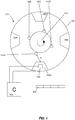
- a BLDC 100 is shown in Fig. 1 .
- the BLDC comprises a rotor 120 with four magnetic poles 140a, 140b, 140c, 140d and a stator 160 with magnetic poles 180a, 180b, 180c, 180d.
- a rotational direction of the rotor 120 is shown in Fig. 1 for illustrative purposes only - the rotor 120 may of course rotate in any direction.
- the BLDC 100 may also comprise any number of magnetic poles.
- the magnetic poles may be ferromagnetic poles, current-carrying coils or windings inducing a magnetic field or magnetic poles generated in any other suitable way.
- the BLDC 100 further comprises a sensor 200, such as a Hall sensor 200, mounted on the stator 160 configured to determine a distance D from the sensor 200 and the magnetic poles 140a, 140b, 140c, 140d of the rotor 140.
- a sensor 200 such as a Hall sensor 200
- the BLDC 100 is connected to a PI controller 300.
- One function of the PI controller 300 is to provide input to the BLDC 100 for smooth, continuous operation and any other suitable controller may be used, e.g. a PID controller.
- the PI controller 300 controls the BLDC 100 by applying a control signal consisting of or comprising a pulse train, the width of the pulses controlling the BLDC and being controlled by any suitable method of pulse width modulation (PWM).
- PWM pulse width modulation
- the PI controller 300 is depicted as being connected to only one of the magnetic poles 180 of the stator 160 for clarity only - the BLDC may comprise one or several controllers connected to the different poles in a multitude of ways.
- the controller 300 may be an external controller or built into the motor 100.
- the speed of the BLDC 100 is recorded for a set time. It is then determined whether the speed of the BLDC 100 has been largely constant for said time. This may be performed by checking whether the recorded speed has deviated from its mean speed by more than a pre-determined speed tolerance threshold. Alternatively, this may be performed by checking if a control signal to the motor is constant or is within a tolerance band during the set time. When it is assured that the BLDC 100 is running at a constant speed, the settings of the PI controller 300 are saved into a memory 400.
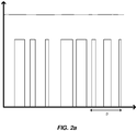
- Fig. 2a the input signal is depicted as a pulse train with varying pulse width, and is output by the PI controller 300. A portion of the pulse train is denoted by the letter 'p'.
- the angular velocity of the rotor 120 is depicted as a near constant above the pulse train.
- Fig. 2a does not correspond to any particular scale, and is included for illustrative purposes only.
- the input signal to the motor 100 may be constant, periodic or semi-periodic and is not constrained to any particular profile as long as it has given rise to a constant rotational speed of the rotor 120.
- the input signal may consist of current pulses, pulses of increased voltage, pulses of any other physical quantity translatable to input to a BLDC as well as a continuous signal.
- the speed of the BLDC 100 is thus controlled by modulating the width of the pulses of the input signal in the described embodiment.
- the memory 400 may be any device suitable for recording of numerical values.
- the control loop of the PI controller 300 is then set to an open mode of operation, wherein the output of the PI controller does not depend on any input.
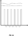
- Fig. 2b The pulses are now of the same width, and the input is thus semi-periodical.
- the pulses need not be set to be the same width; any input signal assumed to drive the BLDC 100 with a constant speed may be used.
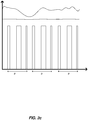
- figure 2c where the portion of the pulse train denoted by 'p' is repeated to produce a semi-periodic, non-constant signal which is assumed to give rise to a constant rotational speed of the motor.
- the speed again shown above the pulse train, is now shown as having much greater variations in both figures 2b and 2c .
- the saved settings of the PI controller are used in both cases to generate a control signal to the BLDC 100 which is assumed to keep the BLDC 100 at a constant speed. However, due to an non-uniform/non-symmetric load the speed will vary when then control signal assumed to keep the BLDC 100 at a constant speed is used in an open mode of operation.
- the Hall sensor 200 is used to detect the passing of the magnetic poles of the rotor which will be registered as a pulse from the Hall sensor 200. The length of this pulse is measured and recorded in the memory 400. From the length of the pulse, the speed of the rotor 120 can be calculated. It is possible to measure the speed directly, for instance by use of an optical sensor or by other means. The rotational speed may e.g. be determined using a so-called encoder. In the described method, a single Hall sensor 200 associated to a single magnetic pole 180a records only pulses from a certain selected magnetic pole 140a of the rotor 120, skipping the other magnetic poles 140b, 140c, 140d of the rotor 120. This provides measurements independent of variations in e.g.
- the variation in speed of the rotor 120 is then calculated. As the load will typically revolve much slower than the rotor 120, at each turn of the rotor 120 a new position of the load is recorded. The variations in speed of the rotor 120, expressed as differences between recorded speeds, are compared to a speed variation threshold value.
- the variations or differences between recorded speeds is indicated as the lines a-h in Fig. 4 .
- the upper horizontal dashed line indicates the first threshold value.
- the lower horizontal dashed line indicates the second threshold value. If the differences are greater than the speed variation threshold values, it is concluded that a load is present. Otherwise, it is concluded that the load is lost.
- the measurements take place over a time interval - the comparison to the threshold value may be made after all the measurements have been made, or they may be compared on-the-fly as suitable.
- the difference a is lower than the first threshold value but higher than the second threshold value. It will not cause a conclusion that load is present but it will increase a counter.
- the differences b, d, f, h are below the second threshold value and will not be considered as indicator concerning load being present.
- the difference c will also increase the counter since it is lower than the first threshold value but higher than the second threshold value. The number of such differences a and c will be compared with a predetermined third threshold value. If the threshold value is greater than two a conclusion concerning load being present or not is not yet drawn after evaluation of difference c.
- the difference e is higher than the first threshold value and as a result thereof it is concluded that a load is present.
- difference e would not have been that high and instead would have been a difference below the second threshold value, e.g. a value corresponding to the differences b, d, f, g, no conclusion concerning load being present would have drawn and the measurement would have continued.
- the second threshold value e.g. a value corresponding to the differences b, d, f, g
- the difference g will also increase the counter since it is lower than the first threshold value but higher than the second threshold value.
- the number of such differences a, c and g will be compared with a predetermined third threshold value. If the third threshold value is three, the difference g will in this case result in a conclusion that load is present. This may be regarded as an absolute comparison with a numerical threshold value indicating a number.
- the comparisons may be compared with the second threshold value and then the relative occurrence of comparisons above the second threshold value and comparisons below the second threshold value may be determined, wherein the relative occurrence of comparisons above/below the second threshold value is compared with a third threshold value which has been determined on beforehand as a relative occurrence above which it may be concluded that a load is present.
- Fig. 3 shows a system 700 comprising a rotary heat exchanger 500, interchangeably referred to as the load 500 in the following text, connected to a BLDC 100 by way of a band 600.
- the load 500 can be any rotationally motivated load.
- the band may of course also be a chain, or any other suitable driving arrangement for a rotationally motivated load 500.
- the load 500 may also be connected directly to the motor shaft.
- the load 500 may alternatively be connected to the motor shaft by a gear arrangement.
- the rotary heat exchanger 500 is light enough in the sense that once the BLDC 100 has accelerated it to a constant speed it will not give rise to any easily measurable current or voltage variations in the BLDC 100.
- the rotary heat exchanger 500 is often relatively heavy to accelerate to speed and thereafter they will be rotated with a minimum of effort. Thereby the motor 100 is comparably strong compared to the load it will be running with in continuous use.
- Fig. 3 shows the load 500 as being considerably larger in diameter than the rotor 120 of the BLDC 100, at least thereby ensuring that the sensor 200 in the BLDC 100 measures the distance between a magnetic pole 140a of the rotor 120 and the sensor 200 of the stator 160 at a plurality of occasions during a revolution of the load 500.
- the BLDC 100 can of course also comprise a transmission system, or a transmission system may be placed between the rotor 120 and the load 500.
- a computer 800 is connected to the system 700, comprising a memory 400 (not pictured) suitable for recording the speed of the rotor 120, the speed variations given rise to by the load 500, the various threshold value for determining constant speed of the rotor 120 before a load check is performed, the threshold value for determining whether speed variations of the BLDC 100 are of significance as well as the settings of the PI controller 300 of the BLDC 100 and other numerical values of interest. It may for instance be of value to record the magnitude of any speed variations to determine whether the load itself is somehow damaged or stalled at any point of its revolution, or any other diagnostic data that may be concluded from various characteristics of speed variations of a BLDC 100.
Landscapes
- Engineering & Computer Science (AREA)
- Power Engineering (AREA)
- Control Of Motors That Do Not Use Commutators (AREA)
Priority Applications (1)
| Application Number | Priority Date | Filing Date | Title |
|---|---|---|---|
| EP17171733.3A EP3404828B1 (fr) | 2017-05-18 | 2017-05-18 | Procédé et système de détection de charge d'un moteur électrique rotatif |
Applications Claiming Priority (1)
| Application Number | Priority Date | Filing Date | Title |
|---|---|---|---|
| EP17171733.3A EP3404828B1 (fr) | 2017-05-18 | 2017-05-18 | Procédé et système de détection de charge d'un moteur électrique rotatif |
Publications (3)
| Publication Number | Publication Date |
|---|---|
| EP3404828A1 true EP3404828A1 (fr) | 2018-11-21 |
| EP3404828B1 EP3404828B1 (fr) | 2023-09-06 |
| EP3404828C0 EP3404828C0 (fr) | 2023-09-06 |
Family
ID=58873611
Family Applications (1)
| Application Number | Title | Priority Date | Filing Date |
|---|---|---|---|
| EP17171733.3A Active EP3404828B1 (fr) | 2017-05-18 | 2017-05-18 | Procédé et système de détection de charge d'un moteur électrique rotatif |
Country Status (1)
| Country | Link |
|---|---|
| EP (1) | EP3404828B1 (fr) |
Citations (3)
| Publication number | Priority date | Publication date | Assignee | Title |
|---|---|---|---|---|
| DE4432058A1 (de) * | 1994-09-09 | 1996-03-14 | Bosch Gmbh Robert | Schaltung zum Betreiben eines Elektromotors |
| DE19901708A1 (de) * | 1999-01-18 | 2000-07-27 | Eberspaecher J Gmbh & Co | Drehzahlgeregelter Elektromotor ohne Motorstrombegrenzung, insbesondere drehzahlgeregelter Brennermotor eines Kraftfahrzeug-Heizgerätes |
| US20110187355A1 (en) * | 2006-08-18 | 2011-08-04 | Christopher David Dixon | Method of processing encoder signals |
-
2017
- 2017-05-18 EP EP17171733.3A patent/EP3404828B1/fr active Active
Patent Citations (3)
| Publication number | Priority date | Publication date | Assignee | Title |
|---|---|---|---|---|
| DE4432058A1 (de) * | 1994-09-09 | 1996-03-14 | Bosch Gmbh Robert | Schaltung zum Betreiben eines Elektromotors |
| DE19901708A1 (de) * | 1999-01-18 | 2000-07-27 | Eberspaecher J Gmbh & Co | Drehzahlgeregelter Elektromotor ohne Motorstrombegrenzung, insbesondere drehzahlgeregelter Brennermotor eines Kraftfahrzeug-Heizgerätes |
| US20110187355A1 (en) * | 2006-08-18 | 2011-08-04 | Christopher David Dixon | Method of processing encoder signals |
Also Published As
| Publication number | Publication date |
|---|---|
| EP3404828B1 (fr) | 2023-09-06 |
| EP3404828C0 (fr) | 2023-09-06 |
Similar Documents
| Publication | Publication Date | Title |
|---|---|---|
| JP5331370B2 (ja) | ステッピングモータの脱調状態検出方法 | |
| US20090218969A1 (en) | Motor drive control device and motor drive control system | |
| CN108169672B (zh) | 风扇电动机控制装置 | |
| US10177638B2 (en) | Rotor position encoder for an electronically commutated electric machine having a reference encoder | |
| JP2009002516A (ja) | 磁気軸受されたロータを有する電気機器を始動するための方法および装置 | |
| US9906185B2 (en) | Method for detecting a short circuit in a synchronous machine fitted with an angular position sensor | |
| US8278861B2 (en) | External disturbance detection system and method for two-phase motor control systems | |
| US11101754B2 (en) | Stall detection in stepper motors using differential back-EMF between rising and falling commutation phase of motor current | |
| AU2015220658B2 (en) | Method for measuring the ageing of permanent magnets of a synchronous machine fitted with an angular position sensor | |
| CN108120454A (zh) | 一种增量编码器的角度检测方法 | |
| EP3404828B1 (fr) | Procédé et système de détection de charge d'un moteur électrique rotatif | |
| US8896257B2 (en) | Motor control device and out-of-step detecting method of stepping motor | |
| US10333451B2 (en) | Controller and method for detecting a blocked state of an electrical machine | |
| JP2020005482A5 (fr) | ||
| CN105227026B (zh) | 轴向通量永磁电机状态监测 | |
| JP5828710B2 (ja) | 回転子に永久磁石を用いた電動機の特性判定方法 | |
| JP5255345B2 (ja) | コギングトルクの測定方法及びコギングトルク測定装置 | |
| JP2008278580A (ja) | モータの静止摩擦トルク検査方法および装置 | |
| EP2955823A1 (fr) | Procédé et système permettant de déterminer un décalage entre un détecteur et un point sur un moteur | |
| CN107155392A (zh) | 电力转换装置和电力转换装置的控制方法 | |
| KR102265505B1 (ko) | 모터 구동 장치 | |
| CN113711488B (zh) | 使用磁通门传感器的机器滑动和方向感测 | |
| US11228266B2 (en) | Synchronous machine and method for regulating the rotational speed of the synchronous machine without sensors | |
| EP3182577B1 (fr) | Ensemble de machine électrique, système de production d'énergie électrique et procédé de commande d'ensemble de machine électrique | |
| KR100331532B1 (ko) | 초고속 디스크형 모터의 특성시험 방법 및 장치 |
Legal Events
| Date | Code | Title | Description |
|---|---|---|---|
| PUAI | Public reference made under article 153(3) epc to a published international application that has entered the european phase |
Free format text: ORIGINAL CODE: 0009012 |
|
| STAA | Information on the status of an ep patent application or granted ep patent |
Free format text: STATUS: THE APPLICATION HAS BEEN PUBLISHED |
|
| AK | Designated contracting states |
Kind code of ref document: A1 Designated state(s): AL AT BE BG CH CY CZ DE DK EE ES FI FR GB GR HR HU IE IS IT LI LT LU LV MC MK MT NL NO PL PT RO RS SE SI SK SM TR |
|
| AX | Request for extension of the european patent |
Extension state: BA ME |
|
| STAA | Information on the status of an ep patent application or granted ep patent |
Free format text: STATUS: REQUEST FOR EXAMINATION WAS MADE |
|
| 17P | Request for examination filed |
Effective date: 20190521 |
|
| RBV | Designated contracting states (corrected) |
Designated state(s): AL AT BE BG CH CY CZ DE DK EE ES FI FR GB GR HR HU IE IS IT LI LT LU LV MC MK MT NL NO PL PT RO RS SE SI SK SM TR |
|
| STAA | Information on the status of an ep patent application or granted ep patent |
Free format text: STATUS: EXAMINATION IS IN PROGRESS |
|
| 17Q | First examination report despatched |
Effective date: 20210224 |
|
| GRAP | Despatch of communication of intention to grant a patent |
Free format text: ORIGINAL CODE: EPIDOSNIGR1 |
|
| STAA | Information on the status of an ep patent application or granted ep patent |
Free format text: STATUS: GRANT OF PATENT IS INTENDED |
|
| INTG | Intention to grant announced |
Effective date: 20230414 |
|
| GRAS | Grant fee paid |
Free format text: ORIGINAL CODE: EPIDOSNIGR3 |
|
| GRAA | (expected) grant |
Free format text: ORIGINAL CODE: 0009210 |
|
| STAA | Information on the status of an ep patent application or granted ep patent |
Free format text: STATUS: THE PATENT HAS BEEN GRANTED |
|
| AK | Designated contracting states |
Kind code of ref document: B1 Designated state(s): AL AT BE BG CH CY CZ DE DK EE ES FI FR GB GR HR HU IE IS IT LI LT LU LV MC MK MT NL NO PL PT RO RS SE SI SK SM TR |
|
| REG | Reference to a national code |
Ref country code: GB Ref legal event code: FG4D |
|
| REG | Reference to a national code |
Ref country code: CH Ref legal event code: EP |
|
| REG | Reference to a national code |
Ref country code: DE Ref legal event code: R096 Ref document number: 602017073677 Country of ref document: DE |
|
| REG | Reference to a national code |
Ref country code: IE Ref legal event code: FG4D |
|
| U01 | Request for unitary effect filed |
Effective date: 20231005 |
|
| U07 | Unitary effect registered |
Designated state(s): AT BE BG DE DK EE FI FR IT LT LU LV MT NL PT SE SI Effective date: 20231016 |
|
| PG25 | Lapsed in a contracting state [announced via postgrant information from national office to epo] |
Ref country code: GR Free format text: LAPSE BECAUSE OF FAILURE TO SUBMIT A TRANSLATION OF THE DESCRIPTION OR TO PAY THE FEE WITHIN THE PRESCRIBED TIME-LIMIT Effective date: 20231207 |
|
| PG25 | Lapsed in a contracting state [announced via postgrant information from national office to epo] |
Ref country code: RS Free format text: LAPSE BECAUSE OF FAILURE TO SUBMIT A TRANSLATION OF THE DESCRIPTION OR TO PAY THE FEE WITHIN THE PRESCRIBED TIME-LIMIT Effective date: 20230906 Ref country code: NO Free format text: LAPSE BECAUSE OF FAILURE TO SUBMIT A TRANSLATION OF THE DESCRIPTION OR TO PAY THE FEE WITHIN THE PRESCRIBED TIME-LIMIT Effective date: 20231206 Ref country code: HR Free format text: LAPSE BECAUSE OF FAILURE TO SUBMIT A TRANSLATION OF THE DESCRIPTION OR TO PAY THE FEE WITHIN THE PRESCRIBED TIME-LIMIT Effective date: 20230906 Ref country code: GR Free format text: LAPSE BECAUSE OF FAILURE TO SUBMIT A TRANSLATION OF THE DESCRIPTION OR TO PAY THE FEE WITHIN THE PRESCRIBED TIME-LIMIT Effective date: 20231207 |
|
| U42 | Public notification for the european patent with unitary effect |
Free format text: INSPECTION PLACE: MUNICH; ADDRESSEE: CG DRIVES & AUTOMATION SWEDEN AB,SE; COMMUNICATION OF THE DATE OF REGISTRATION OF UNITARY EFFECT PURSUANT TO RULE 7(1) UPR (EPO FORM 7030 DATED 13/12/2023) |
|
| U1N | Appointed representative for the unitary patent procedure changed after the registration of the unitary effect |
Representative=s name: AWA SWEDEN AB; SE |
|
| PG25 | Lapsed in a contracting state [announced via postgrant information from national office to epo] |
Ref country code: IS Free format text: LAPSE BECAUSE OF FAILURE TO SUBMIT A TRANSLATION OF THE DESCRIPTION OR TO PAY THE FEE WITHIN THE PRESCRIBED TIME-LIMIT Effective date: 20240106 |
|
| PG25 | Lapsed in a contracting state [announced via postgrant information from national office to epo] |
Ref country code: ES Free format text: LAPSE BECAUSE OF FAILURE TO SUBMIT A TRANSLATION OF THE DESCRIPTION OR TO PAY THE FEE WITHIN THE PRESCRIBED TIME-LIMIT Effective date: 20230906 |
|
| PG25 | Lapsed in a contracting state [announced via postgrant information from national office to epo] |
Ref country code: SM Free format text: LAPSE BECAUSE OF FAILURE TO SUBMIT A TRANSLATION OF THE DESCRIPTION OR TO PAY THE FEE WITHIN THE PRESCRIBED TIME-LIMIT Effective date: 20230906 Ref country code: RO Free format text: LAPSE BECAUSE OF FAILURE TO SUBMIT A TRANSLATION OF THE DESCRIPTION OR TO PAY THE FEE WITHIN THE PRESCRIBED TIME-LIMIT Effective date: 20230906 Ref country code: IS Free format text: LAPSE BECAUSE OF FAILURE TO SUBMIT A TRANSLATION OF THE DESCRIPTION OR TO PAY THE FEE WITHIN THE PRESCRIBED TIME-LIMIT Effective date: 20240106 Ref country code: ES Free format text: LAPSE BECAUSE OF FAILURE TO SUBMIT A TRANSLATION OF THE DESCRIPTION OR TO PAY THE FEE WITHIN THE PRESCRIBED TIME-LIMIT Effective date: 20230906 Ref country code: CZ Free format text: LAPSE BECAUSE OF FAILURE TO SUBMIT A TRANSLATION OF THE DESCRIPTION OR TO PAY THE FEE WITHIN THE PRESCRIBED TIME-LIMIT Effective date: 20230906 Ref country code: SK Free format text: LAPSE BECAUSE OF FAILURE TO SUBMIT A TRANSLATION OF THE DESCRIPTION OR TO PAY THE FEE WITHIN THE PRESCRIBED TIME-LIMIT Effective date: 20230906 |
|
| U20 | Renewal fee for the european patent with unitary effect paid |
Year of fee payment: 8 Effective date: 20240416 |
|
| PG25 | Lapsed in a contracting state [announced via postgrant information from national office to epo] |
Ref country code: PL Free format text: LAPSE BECAUSE OF FAILURE TO SUBMIT A TRANSLATION OF THE DESCRIPTION OR TO PAY THE FEE WITHIN THE PRESCRIBED TIME-LIMIT Effective date: 20230906 |
|
| REG | Reference to a national code |
Ref country code: DE Ref legal event code: R097 Ref document number: 602017073677 Country of ref document: DE |
|
| PLBE | No opposition filed within time limit |
Free format text: ORIGINAL CODE: 0009261 |
|
| STAA | Information on the status of an ep patent application or granted ep patent |
Free format text: STATUS: NO OPPOSITION FILED WITHIN TIME LIMIT |
|
| 26N | No opposition filed |
Effective date: 20240607 |
|
| REG | Reference to a national code |
Ref country code: CH Ref legal event code: PL |
|
| PG25 | Lapsed in a contracting state [announced via postgrant information from national office to epo] |
Ref country code: MC Free format text: LAPSE BECAUSE OF FAILURE TO SUBMIT A TRANSLATION OF THE DESCRIPTION OR TO PAY THE FEE WITHIN THE PRESCRIBED TIME-LIMIT Effective date: 20230906 |
|
| GBPC | Gb: european patent ceased through non-payment of renewal fee |
Effective date: 20240518 |
|
| PG25 | Lapsed in a contracting state [announced via postgrant information from national office to epo] |
Ref country code: MC Free format text: LAPSE BECAUSE OF FAILURE TO SUBMIT A TRANSLATION OF THE DESCRIPTION OR TO PAY THE FEE WITHIN THE PRESCRIBED TIME-LIMIT Effective date: 20230906 Ref country code: CH Free format text: LAPSE BECAUSE OF NON-PAYMENT OF DUE FEES Effective date: 20240531 |
|
| PG25 | Lapsed in a contracting state [announced via postgrant information from national office to epo] |
Ref country code: IE Free format text: LAPSE BECAUSE OF NON-PAYMENT OF DUE FEES Effective date: 20240518 |
|
| PG25 | Lapsed in a contracting state [announced via postgrant information from national office to epo] |
Ref country code: GB Free format text: LAPSE BECAUSE OF NON-PAYMENT OF DUE FEES Effective date: 20240518 |
|
| U20 | Renewal fee for the european patent with unitary effect paid |
Year of fee payment: 9 Effective date: 20250416 |
|
| PG25 | Lapsed in a contracting state [announced via postgrant information from national office to epo] |
Ref country code: CY Free format text: LAPSE BECAUSE OF FAILURE TO SUBMIT A TRANSLATION OF THE DESCRIPTION OR TO PAY THE FEE WITHIN THE PRESCRIBED TIME-LIMIT; INVALID AB INITIO Effective date: 20170518 |
|
| PG25 | Lapsed in a contracting state [announced via postgrant information from national office to epo] |
Ref country code: HU Free format text: LAPSE BECAUSE OF FAILURE TO SUBMIT A TRANSLATION OF THE DESCRIPTION OR TO PAY THE FEE WITHIN THE PRESCRIBED TIME-LIMIT; INVALID AB INITIO Effective date: 20170518 |