EP3404840A1 - Sender, sendeverfahren, empfänger und empfangsverfahren - Google Patents
Sender, sendeverfahren, empfänger und empfangsverfahren Download PDFInfo
- Publication number
- EP3404840A1 EP3404840A1 EP17738310.6A EP17738310A EP3404840A1 EP 3404840 A1 EP3404840 A1 EP 3404840A1 EP 17738310 A EP17738310 A EP 17738310A EP 3404840 A1 EP3404840 A1 EP 3404840A1
- Authority
- EP
- European Patent Office
- Prior art keywords
- waveguide
- receiver
- signal
- communication
- level
- Prior art date
- Legal status (The legal status is an assumption and is not a legal conclusion. Google has not performed a legal analysis and makes no representation as to the accuracy of the status listed.)
- Withdrawn
Links
Images








Classifications
-
- H—ELECTRICITY
- H01—ELECTRIC ELEMENTS
- H01P—WAVEGUIDES; RESONATORS, LINES, OR OTHER DEVICES OF THE WAVEGUIDE TYPE
- H01P3/00—Waveguides; Transmission lines of the waveguide type
- H01P3/16—Dielectric waveguides, i.e. without a longitudinal conductor
- H01P3/165—Non-radiating dielectric waveguides
-
- H—ELECTRICITY
- H04—ELECTRIC COMMUNICATION TECHNIQUE
- H04L—TRANSMISSION OF DIGITAL INFORMATION, e.g. TELEGRAPHIC COMMUNICATION
- H04L27/00—Modulated-carrier systems
- H04L27/0002—Modulated-carrier systems analog front ends; means for connecting modulators, demodulators or transceivers to a transmission line
-
- H—ELECTRICITY
- H04—ELECTRIC COMMUNICATION TECHNIQUE
- H04B—TRANSMISSION
- H04B1/00—Details of transmission systems, not covered by a single one of groups H04B3/00 - H04B13/00; Details of transmission systems not characterised by the medium used for transmission
- H04B1/38—Transceivers, i.e. devices in which transmitter and receiver form a structural unit and in which at least one part is used for functions of transmitting and receiving
- H04B1/40—Circuits
-
- H—ELECTRICITY
- H04—ELECTRIC COMMUNICATION TECHNIQUE
- H04B—TRANSMISSION
- H04B17/00—Monitoring; Testing
- H04B17/10—Monitoring; Testing of transmitters
- H04B17/15—Performance testing
- H04B17/17—Detection of non-compliance or faulty performance, e.g. response deviations
-
- H—ELECTRICITY
- H04—ELECTRIC COMMUNICATION TECHNIQUE
- H04B—TRANSMISSION
- H04B3/00—Line transmission systems
- H04B3/52—Systems for transmission between fixed stations via waveguides
-
- H—ELECTRICITY
- H04—ELECTRIC COMMUNICATION TECHNIQUE
- H04Q—SELECTING
- H04Q1/00—Details of selecting apparatus or arrangements
- H04Q1/18—Electrical details
- H04Q1/20—Testing circuits or apparatus; Circuits or apparatus for detecting, indicating, or signalling faults or troubles
- H04Q1/22—Automatic arrangements
- H04Q1/24—Automatic arrangements for connection devices
-
- H—ELECTRICITY
- H01—ELECTRIC ELEMENTS
- H01Q—ANTENNAS, i.e. RADIO AERIALS
- H01Q13/00—Waveguide horns or mouths; Slot antennas; Leaky-waveguide antennas; Equivalent structures causing radiation along the transmission path of a guided wave
- H01Q13/06—Waveguide mouths
Definitions
- the present technology relates to a transmitter, a transmission method, a receiver, and a reception method, and particularly to a transmitter, a transmission method, a receiver, and a reception method that can keep upsizing and cost increase to a minimum.
- a method is drawing attention that uses communication apparatuses for millimeter wave communication that send and receive data by modulating the data into a millimeter wave band signal (millimeter wave) (refer, for example, to PTL 1).
- a millimeter wave band signal millimeter wave
- a modulated signal acquired by modulating large capacity (high rate) data into a millimeter wave turns out to be a wide-band signal.
- a wide-band modulated signal it is necessary, from the viewpoint of compliance with the Radio Wave Law and other laws regulating radio wave, to ensure (approximate) freedom from radio wave leakage causing external leakage of modulated signal radio wave during transmission and reception of the modulated signal between communication apparatuses engaging in millimeter wave communication.
- a method of sending and receiving a modulated signal without any radio wave leakage for example, there is a method of providing waveguides in communication apparatuses for millimeter wave communication and sending a modulated signal from one of the communication apparatuses to the other communication apparatus in the case where the waveguide of one of the communication apparatuses and the waveguide of the other communication apparatus are in contact with each other.
- the present technology has been devised in light of such circumstances, and it is an object of the present technology to keep upsizing and cost increase to a minimum.
- a transmitter of the present technology has a detection mode and a communication mode as operation modes.
- the detection mode detects contact between a first waveguide on a side of the transmitter and a second waveguide on a side of a receiver.
- the communication mode sends a modulated signal, acquired through frequency conversion of a baseband signal, via the first and second waveguides.
- the transmitter sends a given signal to the first waveguide in the detection mode, goes from the detection mode to the communication mode in response to the given signal received by the receiver via the second waveguide, and sends the modulated signal via the first and second waveguides in the communication mode.
- a transmission method of the present technology is a transmission method of a transmitter having a detection mode and a communication mode as operation modes.
- the detection mode detects contact between a first waveguide on a side of the transmitter and a second waveguide on a side of a receiver.
- the communication mode sends a modulated signal, acquired through frequency conversion of a baseband signal, via the first and second waveguides.
- the transmitter sends a given signal to the first waveguide in the detection mode, goes from the detection mode to the communication mode in response to the given signal received by the receiver via the second waveguide, and sends the modulated signal via the first and second waveguides in the communication mode.
- a given signal is sent to the first waveguide in the detection mode, and the operation mode is switched from the detection mode to the communication mode in response to the given signal received by the receiver via the second waveguide. Then, the modulated signal is sent via the first and second waveguides in the communication mode.
- a receiver of the present technology has a detection mode and a communication mode as operation modes.
- the detection mode detects contact between a first waveguide on a side of a transmitter and a second waveguide on a side of the receiver.
- the communication mode receives a modulated signal, acquired through frequency conversion of a baseband signal, via the first and second waveguides.
- the receiver receives a given signal via the second waveguide in the detection mode, goes from the detection mode to the communication mode in response to the given signal via the second waveguide, and receives the modulated signal via the first and second waveguides in the communication mode.
- a reception method of the present technology is a reception method of a receiver having a detection mode and a communication mode as operation modes.
- the detection mode detects contact between a first waveguide on a side of a transmitter and a second waveguide on a side of the receiver.
- the communication mode receives a modulated signal, acquired through frequency conversion of a baseband signal, via the first and second waveguides.
- the receiver receives a given signal via the second waveguide in the detection mode, goes from the detection mode to the communication mode in response to the given signal via the second waveguide, and receives the modulated signal via the first and second waveguides in the communication mode.
- a given signal is received via the second waveguide in the detection mode, and the operation mode is switched from the detection mode to the communication mode in response to the given signal received via the second waveguide. Then, the modulated signal is received via the first and second waveguides in the communication mode.
- the transmitter and the receiver may be independent apparatuses or internal blocks included in an apparatus.
- FIG. 1 is a block diagram illustrating a configuration example of an embodiment of a communication system to which the present technology is applied.
- the communication system has communication apparatuses 100 and 200.
- the communication apparatuses 100 and 200 are communication apparatuses for millimeter wave communication that send and receive data by modulating the data, for example, into a millimeter wave band signal (millimeter wave), and the communication apparatuses 100 and 200 exchange data by sending and receiving a modulated signal (high frequency signal) acquired by modulating data into a millimeter wave band.
- a modulated signal high frequency signal
- a millimeter wave ((modulated) signal in the millimeter wave band) refers to a signal whose frequency spans approximately from 30 to 300 GHz, i.e., whose wavelength spans approximately from 1 to 10 mm.
- a millimeter wave band signal it is possible to transport data at a high data rate (high rate) thanks to its high frequency.
- a millimeter wave band carrier at approximately 60 GHz permits transmission and reception of data approximately at the rate of 11 Gbps.
- a millimeter wave band signal it is possible to achieve communication using a variety of kinds of transport channels.
- a millimeter wave band signal it is possible to achieve communication whose transport channel is a space such as free space (wireless communication) using small antennas. Also, according to a millimeter wave band signal, it is possible to achieve communication whose transport channel is a metallic wire or communication whose transport channel is a dielectric such as plastic.
- transmission and reception of a millimeter wave band modulated signal takes place between the communication apparatuses 100 and 200 without wireless license and while complying with laws regulating radio wave.
- transmission and reception of a millimeter wave band modulated signal takes place between the communication apparatuses 100 and 200 in the case where the communication apparatuses 100 and 200 are (nearly) in contact with each other, i.e., in the case where radio wave leakage outside the communication apparatuses 100 and 200 does not occur (hardly occurs) in such a manner as to ensure (approximate) freedom from radio wave leakage causing external leakage of modulated signal radio wave.
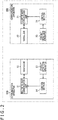
- FIG. 2 is a block diagram illustrating a first configuration example of the communication apparatuses 100 and 200 illustrated in FIG. 1 .
- the communication apparatus 100 has a millimeter wave communication unit 11, a waveguide 12, a contact detection apparatus 13, and a control section 14.
- the millimeter wave communication unit 11 converts, in frequency, a baseband signal, target data to be sent (modulates the baseband signal), into a millimeter wave band modulated signal and sends the modulated signal to the waveguide 12.
- the millimeter wave communication unit 11 receives the millimeter wave band modulated signal sent from the communication apparatus 200 via the waveguide 12, i.e., the modulated signal that has propagated through the waveguide 12, converts, in frequency, the signal (demodulates the signal) into a baseband signal, and outputs the baseband signal.
- the waveguide 12 includes, for example, a dielectric such as plastic.
- the waveguide 12 is in the shape of a long narrow plate. An end face thereof at one longitudinal end is connected to the millimeter wave communication unit 11, and an end face at the other end is exposed on the outside of the communication apparatus 100 (e.g., on a housing surface).
- the contact detection apparatus 13 detects whether the communication apparatus 100 and the communication apparatus 200 (or other communication apparatus capable of millimeter wave communication) are in contact with each other.
- the contact detection apparatus 13 performs contact detection to determine whether the waveguide 12 of the communication apparatus 100 and a waveguide 22 of the communication apparatus 200 which will be described later (whether the end faces thereof) are in contact with each other and supplies the detection result of the contact detection to the control section 14.
- the control section 14 controls the millimeter wave communication unit 11 in response to the detection result of the contact detection from the contact detection apparatus 13 and so on.
- the control section 14 controls the millimeter wave communication unit 11 to send a millimeter wave band signal (modulated signal or carrier) from the millimeter wave communication unit 11.
- control section 14 controls the millimeter wave communication unit 11 to limit (inhibit) the transmission of a millimeter wave band signal from the millimeter wave communication unit 11.
- the communication apparatus 200 has a millimeter wave communication unit 21, a waveguide 22, a contact detection apparatus 23, and a control section 24.
- the millimeter wave communication unit 21 through the control section 24 are configured similarly to the millimeter wave communication unit 11 through the control section 14, respectively. Therefore, the description thereof will be omitted.
- detection methods used with the contact detection apparatuses 13 and 23 are a method using pressure-sensitive conductive rubber, a method detecting capacitive change, a method detecting deformation caused by blocking of light, a method detecting an optical touch image, a method detecting continuity or discontinuity, a method using an acoustic resonance tactile element, and a method detecting contact resistance change.
- the control section 14 causes the millimeter wave communication unit 11 to send a millimeter wave band modulated signal as necessary.
- the millimeter wave communication unit 11 converts, in frequency, a baseband signal from a circuit that is not depicted into a millimeter wave band modulated signal and sends the signal.
- the modulated signal sent from the millimeter wave communication unit 11 propagates through the waveguide 12 and further through the waveguide 22 of the communication apparatus 200 that is in contact with the waveguide 12 and is received by the millimeter wave communication unit 21.
- the millimeter wave communication unit 21 converts, in frequency, the modulated signal received via the waveguide 22 (modulated signal that has propagated through the waveguide 22) into a baseband signal and supplies the signal to a circuit that is not depicted.
- the control section 24 causes the millimeter wave communication unit 21 to send a millimeter wave band modulated signal as necessary.
- the millimeter wave communication unit 21 converts, in frequency, a baseband signal from a circuit that is not depicted into a millimeter wave band modulated signal and sends the signal.
- the modulated signal sent from the millimeter wave communication unit 21 propagates through the waveguide 22 and further through the waveguide 12 of the communication apparatus 100 that is in contact with the waveguide 22 and received by the millimeter wave communication unit 11.
- the millimeter wave communication unit 11 converts, in frequency, the modulated signal received via the waveguide 22 into a baseband signal and supplies the signal to a circuit that is not depicted.
- control section 14 limits the transmission of a millimeter wave band signal from the millimeter wave communication unit 11.
- control section 24 limits the transmission of a millimeter wave band signal from the millimeter wave communication unit 21.
- the transmission of millimeter wave band signals from the millimeter wave communication units 11 and 21 is limited. This makes it possible to prevent radiation of a high-level or wide-band signal that may violate laws from the externally exposed end face of the waveguide 12 of the communication apparatus 100 or from the externally exposed end face of the waveguide 22 of the communication apparatus 200.
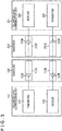
- FIG. 3 is a block diagram illustrating a second configuration example of the communication apparatuses 100 and 200 illustrated in FIG. 1 .
- the communication apparatus 100 has a millimeter wave communication unit 111, a waveguide 112, and a control section 113.
- the millimeter wave communication unit 111 converts, in frequency, a baseband signal, target data to be sent (modulates the baseband signal), into a millimeter wave band modulated signal and sends the modulated signal to the waveguide 112.
- the millimeter wave communication unit 111 receives the millimeter wave band modulated signal sent via the waveguide 112, i.e., the modulated signal that has propagated through the waveguide 112, converts, in frequency, the signal (demodulates the signal) into a baseband signal, and outputs the baseband signal.
- the waveguide 112 includes, for example, a piece of hollow metal filled inside with a dielectric such as plastic.
- the waveguide 112 is in the shape of a long narrow plate. An end face thereof at one longitudinal end is connected to the millimeter wave communication unit 111, and an end face at the other end is exposed on the outside of the communication apparatus 100 (e.g., on a housing surface).
- a millimeter wave band signal sent by the millimeter wave transmitter 111 propagates through the waveguide 112. Further, a millimeter wave band signal to be received by the millimeter wave transmitter 111 propagates through the waveguide 112.
- the control section 113 controls the millimeter wave communication unit 111 in response to the millimeter wave band signal received by the millimeter wave communication unit 111 via the waveguide 112 and so on.
- the millimeter wave communication unit 111 has a detection mode and a communication mode as operation modes.
- the detection mode contact between the waveguide 112 of the communication apparatus 100 and the waveguide 212 of the communication apparatus 200 is detected.
- millimeter wave band modulated signals acquired through frequency conversion of baseband signals, are sent and received via the waveguide 112 and a waveguide 212 between the communication apparatuses 100 and 200.
- the control section 113 sets the operation mode to the detection mode or the communication mode in response to the millimeter wave band signal received by the millimeter wave communication unit 111 via the waveguide 112 and so on.
- the communication apparatus 200 has a millimeter wave communication unit 211, the waveguide 212, and a control section 213.
- the millimeter wave communication unit 211 through the control section 213 are configured similarly to the millimeter wave communication unit 111 through the control section 113, respectively. Therefore, the description thereof will be omitted.
- FIG. 4 is a diagram illustrating a configuration example of the millimeter wave communication units 111 and 211 and the waveguides 112 and 212 illustrated in FIG. 3 .
- the millimeter wave communication unit 111 has a transmitter 121 and a receiver 122.
- the transmitter 121 converts, in frequency, a baseband signal into a millimeter wave band modulated signal and sends the signal to the waveguides 112 from an antenna 123.
- the receiver 122 receives the millimeter wave band modulated signal that has propagated through the waveguide 112 and that is supplied via the antenna 123 and converts, in frequency, the modulated signal into a baseband signal.
- the antenna 123 is used for both transmission and reception and connected to the dielectric included in the waveguide 112.
- the waveguide 112 includes a waveguide that is used for both transmission and reception in response to the fact that the antenna 123 is an antenna that is used for both transmission and reception.
- the waveguide 112 is a waveguide (first waveguide) on the side of the transmitter 121 through which a signal sent by the transmitter 121 propagates and is also a waveguide on the side of the receiver 122 through which a signal to be received by the receiver 122 propagates (will propagate).
- the millimeter wave communication unit 211 has a transmitter 221 and a receiver 222.
- the transmitter 221 and the receiver 222 are configured similarly to the transmitter 121 and the receiver 122, respectively.
- the transmitter 221 sends a millimeter wave band modulated signal to the waveguide 212 from an antenna 223 as does the transmitter 121.
- the receiver 222 receives the millimeter wave band modulated signal that has propagated through the waveguide 212 and that is supplied via the antenna 223.
- the antenna 223 is used for both transmission and reception and connected to the dielectric included in the waveguide 212 as is the antenna 123.
- the waveguide 212 includes a waveguide that is used for both transmission and reception in response to the fact that the antenna 223 is an antenna that is used for both transmission and reception.
- the waveguide 212 is a waveguide on the side of the transmitter 221 through which a signal sent by the transmitter 221 propagates and is also a waveguide (second waveguide) on the side of the receiver 222 through which a signal to be received by the receiver 222 propagates (will propagate).
- the millimeter wave communication units 111 and 211 are capable of bidirectional communication.
- a millimeter wave band modulated signal sent by the transmitter 121 in the millimeter wave communication unit 111 propagates from the antenna 123 through the waveguides 112 and 212 and is received by the receiver 222 via the antenna 223.
- a millimeter wave band modulated signal sent by the transmitter 221 in the millimeter wave communication unit 211 propagates from the antenna 223 through the waveguides 212 and 112 and is received by the receiver 122 via the antenna 123.
- the millimeter wave communication units 111 and 211 are capable of half-duplex communication. Also, in the case where millimeter wave signals of different frequency bands are used by the transmitters 121 and 221, the millimeter wave communication units 111 and 211 are capable of full-duplex communication.
- the millimeter wave communication unit 111 can be configured without the receiver 122, and the millimeter wave communication unit 211 can be configured without the transmitter 221.
- FIG. 5 is a diagram illustrating another configuration example of the millimeter wave communication units 111 and 211 and the waveguides 112 and 212 illustrated in FIG. 3 .
- the case illustrated in FIG. 5 differs from the case illustrated in FIG. 4 in which the communication system has the antennas 123 and 223 and the waveguides 112 and 212 that are used for both transmission and reception in that the communication system has transmission antennas 123S and 223S, reception antennas 123R and 223R, transmission waveguides 112S and 212S, and reception waveguides 112R and 212R.
- the waveguides 112 has the transmission waveguide 112S and the reception waveguide 112R.
- the waveguides 212 has the transmission waveguide 212S and the reception waveguide 212R.
- Each of the waveguides 112S, 112R, 212S, and 212R includes, for example, a piece of hollow metal filled inside with a given dielectric.
- the waveguides 112 and 212 are configured such that when the millimeter wave communication units 111 and 112 are brought into contact with each other, the waveguides 112S and 212R come into contact with each other, and the waveguides 112R and 212S come into contact with each other.
- the antenna 123S is a transmission antenna and connected to a dielectric included in the transmission waveguide 112S.
- the millimeter wave band modulated signal sent by the transmitter 121 propagates from the antenna 123S through the waveguide 112S.
- the antenna 123R is a reception antenna and connected to a dielectric included in the reception waveguide 112R.
- the millimeter wave band modulated signal that propagates through the waveguide 112R is received by the receiver 122 via the antenna 123R.
- the antenna 223S is a transmission antenna and connected to a dielectric included in the transmission waveguide 212S.
- the millimeter wave band modulated signal sent by the transmitter 221 propagates from the antenna 223S through the waveguide 212S.
- the antenna 223R is a reception antenna and connected to a dielectric included in the reception waveguide 212R.
- the millimeter wave band modulated signal that propagates through the waveguide 212R is received by the receiver 222 via the antenna 223R.
- the waveguide 112S is a waveguide (first waveguide) on the side of the transmitter 121 through which a signal sent by the transmitter 121 propagates and the waveguide 212R is also a waveguide (second waveguide) on the side of the receiver 222 through which a signal to be received by the receiver 222 propagates (will propagate).
- the waveguide 212S is a waveguide on the side of the transmitter 221 through which a signal sent by the transmitter 221 propagates and the waveguide 112R is also a waveguide on the side of the receiver 122 through which a signal to be received by the receiver 122 propagates (will propagate).
- the millimeter wave communication units 111 and 211 are capable of full-duplex communication.
- a millimeter wave band modulated signal sent by the transmitter 121 propagates from the antenna 123S through the waveguides 112S and 212R and is received by the receiver 222 via the antenna 223R.
- a millimeter wave band modulated signal sent by the transmitter 221 propagates from the antenna 223S through the waveguides 212S and 112R and is received by the receiver 122 via the antenna 123R.
- each of the waveguides 112 and 212 includes a waveguide that is used for both transmission and reception as illustrated in FIG. 4 but also in the case where the waveguide 112 has the transmission waveguide 112S and the reception waveguide 112R and the waveguide 212 has the transmission waveguide 212S and the reception waveguide 212R as illustrated in FIG. 5 .
- each of the waveguides 112 and 212 includes a waveguide that is used for both transmission and reception for easier description, as illustrated in FIG. 4 .
- FIG. 6 is a diagram illustrating a configuration example of the transmitter 121 and the receiver 122 of the millimeter wave communication unit 111 and the transmitter 221 and the receiver 222 of the millimeter wave communication unit 211.
- the transmitter 121 has a mixer 131, an oscillator 132, an amplifier 133, and switches 134 and 135.
- the mixer 131 is supplied with a baseband signal (BB signal) from a circuit that is not depicted and a millimeter wave band carrier from the oscillator 132.
- BB signal baseband signal
- the mixer 131 converts, in frequency, a baseband signal using a carrier from the oscillator 132 (modulates the carrier in accordance with the baseband signal) by mixing (multiplying) the baseband signal and the carrier from the oscillator 132 and supplies a millimeter wave band modulated signal such as amplitude-modulated (ASK (Amplitude Shift Keying)) signal, acquired as a result thereof, to the amplifier 133.
- ASK Amplitude Shift Keying
- the mixer 133 supplies the carrier from the oscillator 132 to the amplifier 133 in an 'as-is' condition.
- the oscillator 132 generates, for example, a millimeter wave band such as 56 GHz through oscillation and supplies the carrier to the mixer 131.
- the amplifier 133 amplifies the signal (modulated signal or carrier) from the mixer 131 with a given gain as necessary and outputs the amplified signal.
- the signal output from the amplifier 133 is sent to the waveguide 112 (from the antenna 123 ( FIG. 4 )).
- the gain of the amplifier 133 (degree of amplification of the signal from the mixer 133) can be specified in accordance with control performed by the control section 113 ( FIG. 3 ).
- the switches 134 and 135 turn ON or OFF in accordance with control performed by the control section 113 ( FIG. 3 ).
- the amplifier 133 turns ON or OFF.
- the receiver 222 has an amplifier 241, a mixer 242, an LPF (Low Pass Filter) 243, and a switch 244.
- LPF Low Pass Filter
- the amplifier 241 receives a millimeter wave band signal (modulated signal or carrier) that has propagated through the waveguide 212, amplifies the signal with a given gain as necessary, and supplies the amplified signal to the mixer 242.
- a millimeter wave band signal modulated signal or carrier
- the band (reception band) of the millimeter wave band signal amplified by the amplifier 241 can be specified in accordance with control performed by the control section 213 ( FIG. 3 ).
- the mixer 242 converts, in frequency, the millimeter wave band modulated signal from the amplifier 241 into a baseband signal (demodulates the modulated signal into a baseband signal) by performing squared detection that mixes the millimeter wave band modulated signal supplied from the amplifier 241 with itself (squares the modulated signal), and supplies the baseband signal to the LPF 243.
- the LPF 243 performs filtering that passes a low-frequency component of the signal from the mixer 243 and outputs a baseband signal acquired as a result of the filtering.
- the pass band of the LPF 243 can be specified in accordance with control performed by the control section 213.
- the switch 244 turns ON or OFF in accordance with control performed by the control section 213.
- the amplifier 241 turns ON or OFF.
- the receiver 222 converts, in frequency, the millimeter wave band modulated signal into a baseband signal through squared detection
- the transmitter 221 has a mixer 231, an oscillator 232, an amplifier 233, and switches 234 and 235.
- the mixer 231 through the switch 235 are configured similarly to the mixer 131 through the switch 135 of the transmitter 121, respectively. Therefore, the description thereof will be omitted.
- the receiver 122 has an amplifier 141, a mixer 142, an LPF 143, and a switch 144.
- the amplifier 141 through the switch 144 are configured similarly to the amplifier 241 through the switch 244 of the receiver 222, respectively. Therefore, the description thereof will be omitted.
- FIG. 7 is a diagram describing operation modes of the millimeter wave communication units 111 and 211 illustrated in FIG. 3 .
- the millimeter wave communication units 111 and 211 have the detection mode and the communication mode as operation modes.
- the millimeter wave communication units 111 and 211 switch their operation mode from the detection mode to the communication mode.
- a millimeter wave band modulated signal is sent and received between the communication apparatuses 100 and 200 via the waveguides 112 and 212.
- FIG. 8 depicts diagrams describing the detection mode.
- one of the communication apparatuses 100 and 200 makes a request to initiate communication and the other communication apparatus initiates communication in response to the request from one of the communication apparatuses.
- the communication apparatus millimeter wave communication unit that makes a request to initiate communication
- the communication apparatus that initiates communication in response to the request from the initiator will be also referred to as a target.
- the transmitter 121 of the communication apparatus 100 an initiator, sends a given signal to the waveguide 112 (from the antenna 123).
- a narrow-band low-level signal that is not only narrower in band but also lower in level than a millimeter wave band modulated signal sent in the communication mode, for example, can be used as a given signal sent in the detection mode.
- a low-level signal (also referred to as a low-level carrier) that is a millimeter wave band carrier output from the oscillator 132 ( FIG. 6 ) and that is acquired by specifying, for the amplifier 133 ( FIG. 6 ), a smaller gain than that for amplifying a millimeter wave band modulated signal sent in the communication mode, can be used.
- a low-level signal (also referred to as a low-rate modulated signal) that is a modulated signal resulting from modulation of a millimeter wave band carrier with a baseband signal that is smaller in rate (narrower in band) than a baseband signal sent in the communication mode and that is acquired by specifying, for the amplifier 133, a smaller gain than that for amplifying a millimeter wave band modulated signal sent in the communication mode, can be used.
- the narrow-band low-level signal sent by the transmitter 121 to the waveguide 112 in the detection mode propagates through the waveguide 112 and reaches the outer end face of the waveguide 112.
- the outer end face of the waveguide 112 is in contact with a space (e.g., atmosphere).
- a space e.g., atmosphere.
- the narrow-band low-level signal is narrow in band and low in level, it does not cause radio wave emission of a high-level or wide-band signal that would violate laws as a radio wave leakage.
- the narrow-band low-level signal does not reach the communication apparatus 200 from the communication apparatus 100, or even if it does, the narrow-band low-level signal that propagates through the waveguide 212 and is received by the receiver 222 turns out to be extremely small in level.
- FIG. 8A illustrates an example of a level of a narrow-band low-level signal received by the receiver 222 of the communication apparatus 200 in the case where the communication apparatuses 100 and 200 are separated.
- a narrow-band low-level signal smaller in level than a predetermined detection mode threshold is received by the receiver 222.
- the narrow-band low-level signal sent by the transmitter 121 propagates through the waveguides 112 and 212 and reaches and is received by the receiver 222 while maintaining its level to some extent.
- the level of the narrow-band low-level signal received by the receiver 222 via the waveguide 212 increases significantly from the level of the narrow-band low-level signal received by the receiver 222 via the waveguide 212 in the case where the waveguides 112 and 212 are not in contact with each other (in the case where the communication apparatuses 100 and 200 are separated).
- FIG. 8B illustrates an example of a level of a narrow-band low-level signal received by the receiver 222 of the communication apparatus 200 in the case where the waveguide 112 of the communication apparatus 100 and the waveguide 212 of the communication apparatus 200 are separated.
- a narrow-band low-level signal equal to or greater in level than a predetermined detection mode threshold is received by the receiver 222.
- control sections 113 and 213 ( FIG. 3 ) specify an operation mode in response to the narrow-band low-level signal received by the receiver 222 of the communication apparatus 200, a target, via the waveguide 212.
- control sections 113 and 213 switch the operation mode from the detection mode to the communication mode by determining that contact between the waveguides 112 and 212 has been detected.
- the operation mode of the transmitter 121 (communication apparatus 100 having the transmitter 121) and the operation mode of the receiver 222 (communication apparatus 200 having the receiver 222) are switched from the detection mode to the communication mode.
- a predetermined high-rate baseband signal is converted, in frequency, to a millimeter wave band modulated signal with a carrier in the transmitter 121. Further, in the transmitter 121, the modulated signal is amplified with a given high gain by the amplifier 133, and a modulated signal larger in level and larger in frequency band than the narrow-band low-level signal is sent.
- the modulated signal sent by the transmitter 121 propagates through the waveguides 112 and 212 that are in contact with each other and reaches and is received by the receiver 222 while maintaining its level to some extent.
- the modulated signal that is sent by the transmitter 121 and propagates through the waveguides 112 and 212 in the communication mode is a signal larger in level and larger in frequency band than the narrow-band low-level signal.
- the waveguides 112 and 212 are in contact with each other. Therefore, radio wave leakage of the modulated signal as a radio wave does not occur.
- the level of the narrow-band low-level signal sent by the transmitter 121 in the detection mode and the threshold for the detection mode are adjusted in advance to ensure that radio wave leakage in the case of separation between the communication apparatuses 100 and 200 complies with laws regulating radio wave, that the level of the narrow-band low-level signal received by the receiver 222 in the case of separation between the communication apparatuses 100 and 200 is smaller than the detection mode threshold, and that the level of the narrow-band low-level signal received by the receiver 222 in the case of contact between the waveguides 112 and 212 is equal to or larger than the detection mode threshold.
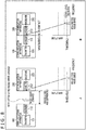
- FIG. 9 is a diagram describing first simulation for investigating a relationship between a waveguide-to-waveguide gap and waveguide-to-waveguide transfer characteristic.
- waveguides in the shape of a long narrow plate having a rectangular cross section were used as the waveguides 112 and 212.
- the waveguides 112 and 212 are surrounded by a piece of metal on the four surfaces orthogonal to the cross section and filled with dielectrics.
- the cross sections of the waveguides 112 and 212 measure 3 mm across and 1 mm down, with the metal of the four surfaces orthogonal to the cross sections being 0.1 mm thick.
- a dielectric having a dielectric constant of 2.1 and a dielectric tangent of 0.001 (Teflon (registered trademark)) is used as the dielectric PA, and a dielectric having a dielectric constant of 10.2 and a dielectric tangent of 0.001 is used as the dielectric PB.
- the waveguides 112 and 212 were arranged such that their end faces were opposed to each other, and the gap between the end faces was set to a variety of distances so as to measure an S-parameter transfer coefficient S21 from the waveguide 112 to the waveguide 212.
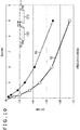
- FIG. 10 is a diagram illustrating results of the first simulation described in FIG. 9 .
- FIG. 10 illustrates a relationship between the waveguide-to-waveguide gap 112 and 212 and the transfer coefficient S21 from the waveguide 112 to the waveguide 212 acquired by the first simulation.
- the transfer coefficient S21 declines more sharply in the case where the dielectric PB is used than in the case where the dielectric PA is used.
- the extent of change (decline) in the transfer coefficient S21 when the distance of the gap between the end faces of the waveguides 112 and 212 changes from a 0 state to a non-0 state can be adjusted not only by the dielectric filled into (the dielectric constant of) the waveguides 112 and 212 but also by the shape of the end faces of the waveguides 112 and 212.
- FIG. 11 is a diagram describing second simulation for investigating the relationship between the waveguide-to-waveguide gap and the waveguide-to-waveguide transfer characteristic.
- waveguides having a cross section in the shape of a rectangular and long narrow plate, surrounded by a piece of metal on the four surfaces orthogonal to the cross section, and filled with dielectrics are used as the waveguides 112 and 212 as in the first simulation.
- the cross sections of the waveguides 112 and 212 measure 1.5 mm across and 0.5 mm down (Wg ⁇ Hg), with the metal of the four surfaces orthogonal to the cross sections being 0.1 mm thick.
- the dielectric PB described in FIG. 9 was used as a dielectric filled into the waveguides 112 and 212.
- the dielectric PB has a dielectric constant of 10.2 and a dielectric tangent of 0.001.
- the waveguides 112 and 212 were arranged such that their end faces were opposed to each other, and the gap between the end faces was set to a variety of distances so as to measure the S-parameter transfer coefficient S21 from the waveguide 112 to the waveguide 212 as in the first simulation.
- FIG. 12 is a diagram illustrating simulation results of the second simulation described in FIG. 11 .
- FIG. 12 illustrates a relationship between a carrier frequency and the transfer coefficient S21 from the waveguide 112 to the waveguide 212 for each of the plurality of gaps between the waveguides 112 and 212 acquired in the second simulation.
- contact between the waveguide 112 of the communication apparatus 100 and the waveguide 212 of the communication apparatus 200 is detected by taking advantage of the fact that the transfer coefficient S21 changes sharply between a state in which the waveguides 112 and 212 are in contact and a state in which the waveguides 112 and 212 are slightly separated.
- FIG. 13 depicts diagrams describing the detection mode and the communication mode.
- FIG. 13A is a diagram describing the detection mode.
- the transmitter 121 of the communication apparatus 100 an initiator, sends a narrow-band low-level signal to the waveguide 112 as described in FIG. 8 .
- a low-level carrier carrier whose level is low
- a low-rate modulated signal modulated signal whose level is low acquired by modulating a carrier with a low-rate (narrow-band) baseband signal
- the narrow-band low-level signal sent by the transmitter 121 to the waveguide 112 propagates through the waveguide 112 and reaches the outer end face of the waveguide 112.
- the outer end face of the waveguide 112 is in contact with a space.
- nearly all the narrow-band low-level signal is reflected by the outer end face of the waveguide 112 because of the difference in dielectric constant. Therefore, there is little radio wave leakage of the narrow-band low-level signal as a radio wave from the outer end face of the waveguide 112.
- the narrow-band low-level signal is narrow in band and low in level, it does not cause radio wave emission of a high-level or wide-band signal that would violate laws as a radio wave leakage.
- the narrow-band low-level signal does not reach the communication apparatus 200 from the communication apparatus 100, or even if it does, the narrow-band low-level signal that propagates through the waveguide 212 and is received by the receiver 222 turns out to be extremely small in level.
- the level of the narrow-band low-level signal received by the receiver 222 is smaller than a predetermined detection mode threshold.
- the communication apparatuses 100 and 200 are kept in the detection mode as an operation mode.
- reception sensitivity of the receiver 222 of the communication apparatus 200 can be narrowed, for example, by narrowing the band of the target signal to be amplified by the amplifier 241 illustrated in FIG. 6 or the pass band of the LPF 243.
- the narrow-band low-level signal sent by the transmitter 121 propagates through the waveguides 112 and 212, and reaches and is received by the receiver 222 while maintaining its level to some extent.
- the level of the narrow-band low-level signal received by the receiver 222 via the waveguide 212 increases significantly from the level of the narrow-band low-level signal received by the receiver 222 via the waveguide 212 in the case where the waveguides 112 and 212 are not in contact with each other and becomes equal to or exceeds the detection mode threshold.
- the communication apparatuses 100 and 200 When the level of the narrow-band low-level signal received by the receiver 222 becomes equal to or exceeds the detection mode threshold, the communication apparatuses 100 and 200 (the transmitter 121 and the receiver 222 of the respective communication apparatuses) switch their operation mode from the detection mode to the communication mode.
- FIG. 13B is a diagram describing the communication mode.
- a predetermined high-rate baseband signal is converted, in frequency, to a millimeter wave band modulated signal with a carrier. Further, in the transmitter 121, the modulated signal is amplified with a given high gain by the amplifier 133 ( FIG. 6 ), and a modulated signal having a larger level and a larger frequency band than the narrow-band low-level signal is sent.
- the modulated signal sent by the transmitter 121 propagates through the waveguides 112 and 212 that are in contact with each other and reaches and is received by the receiver 222 while maintaining its level to some extent.
- the modulated signal that is sent by the transmitter 121 and propagates through the waveguides 112 and 212 in the communication mode is a signal having a larger level and a larger frequency band than the narrow-band low-level signal.
- the waveguides 112 and 212 are in contact with each other. Therefore, no radio wave leakage of the modulated signal as a radio wave does not occur.
- a target narrows the reception band for improving the reception sensitivity of a narrow-band low-level signal in the detection mode
- a modulated signal large in frequency band i.e., a high-rate baseband signal
- FIG. 14 is a flowchart describing an example of operation of the communication apparatus 100, an initiator, and the communication apparatus 200, a target.
- step S11 the operation mode to the detection mode, and the process proceeds to step S12.
- step S12 the transmitter 121 of the communication apparatus 100 sends a narrow-band low-level signal in response to the fact that the operation mode is the detection mode, and the process proceeds to step S13.
- step S13 the control section 113 of the communication apparatus 100 determines whether a signal equal to or larger in level than a threshold has been received by the receiver 122 ( FIG. 6 ).
- the communication apparatus 200 in the case where a narrow-band low-level signal equal to or larger in level than a detection mode threshold has been received by the receiver 222, the communication apparatus 200, a target, sends a reception confirmation signal representing the reception of a narrow-band low-level signal (e.g., a carrier itself or the narrow-band (low-rate) modulated signal resulting from modulation of a carrier with a baseband signal representing the reception of a narrow-band low-level signal) from the transmitter 221.
- a narrow-band low-level signal e.g., a carrier itself or the narrow-band (low-rate) modulated signal resulting from modulation of a carrier with a baseband signal representing the reception of a narrow-band low-level signal
- the reception confirmation signal sent from the communication apparatus 200 propagates through the waveguide 212, and (nearly all the reception confirmation signal) is reflected by the end face exposed on the housing surface of the communication apparatus 100.
- the reception confirmation signal sent from the communication apparatus 200 does not reach the receiver 122 of the communication apparatus 100, or even if it does, the reception confirmation signal received by the receiver 122 of the communication apparatus 100 turns out to be extremely small in level.
- the reception confirmation signal sent from the communication apparatus 200 propagates through the waveguides 212 and 112 and is received at some level by the receiver 122 of the communication apparatus 100.
- a reception confirmation signal equal to or greater in level than the threshold is received by the receiver 122.
- step S13 the control section 113 of the communication apparatus 100 determines whether a reception confirmation signal from the communication apparatus 200 has been received by the receiver 122 at a level equal to or larger than the threshold, that is, whether a reception confirmation signal equal to or larger in level than the threshold has been received.
- step S13 In the case where it is determined in step S13 that a reception confirmation signal equal to or larger in level than the threshold has not been received, that is, in the case where a reception confirmation signal equal to or larger in level than the threshold cannot be received from the communication apparatus 200 because the waveguide 112 of the communication apparatus 100 and the waveguide 212 of the communication apparatus 200 are not in contact with each other, the process returns to step S12, and similar processes are repeated from here onward.
- step S13 determines that a reception confirmation signal equal to or larger in level than the threshold has been received, that is, in the case where the waveguide 112 of the communication apparatus 100 and the waveguide 212 of the communication apparatus 200 are in contact with each other and a reception confirmation signal equal to or larger in level than the threshold has been received by the communication apparatus 100 from the communication apparatus 200, the process proceeds to step S14.
- step S14 the control section 113 of the communication apparatus 100 causes the transmitter 121 to send a mode switching signal that requests the switching of the operation mode from the detection mode to the communication mode (e.g., a carrier itself or a narrow-band modulated signal resulting from modulation of a carrier with a baseband signal requesting the switching to the communication mode), and the process proceeds to step S15.
- a mode switching signal that requests the switching of the operation mode from the detection mode to the communication mode (e.g., a carrier itself or a narrow-band modulated signal resulting from modulation of a carrier with a baseband signal requesting the switching to the communication mode)
- the mode switching signal sent by the receiver 121 of the communication apparatus 100 propagates through the waveguides 112 and 212 that are in contact with each other and is received by the receiver 222 of the communication apparatus 200.
- the communication apparatus 200 sends a switching confirmation signal representing the reception of a mode switching signal from the transmitter 221 as will be described later.
- the switching confirmation signal sent by the transmitter 221 propagates through the waveguides 212 and 112 that are in contact with each other and is received by the receiver 122 of the communication apparatus 100.
- step S15 the communication apparatus 100 goes into standby and waits for a switching confirmation signal sent by the transmitter 221 of the communication apparatus 200, and the process proceeds to step S16.
- step S16 the control section 113 of the communication apparatus 100 determines whether a switching confirmation signal from the communication apparatus 200 has been received by the receiver 122 at a level equal to or larger than the threshold, that is, whether a switching confirmation signal equal to or larger in level than the threshold has been received.
- step S16 In the case where it is determined in step S16 that a switching confirmation signal at a level equal to or larger than the threshold has not been received by the receiver 122, the process returns to step S12, and similar processes are repeated from here onward.
- step S16 determines whether a switching confirmation signal equal to or larger in level than the threshold has been received by the receiver 122. If it is determined in step S16 that a switching confirmation signal equal to or larger in level than the threshold has been received by the receiver 122, the process proceeds to step S17.
- step S16 in the case where, due to the reception of a narrow-band low-level signal equal to or larger in level than the detection mode threshold by the receiver 222 of the communication apparatus 200, a reception confirmation signal and a switching confirmation signal equal to or larger in level than the threshold have been received by the communication apparatus 100 from the communication apparatus 200, the process proceeds from step S16 to step S17.
- step S17 the control section 113 of the communication apparatus 100 sets (switches) the operation mode of the communication apparatus 100 from the detection mode to the communication mode in response to the reception of a reception confirmation signal and a switching confirmation signal equal to or larger in level than the threshold from the communication apparatus 200, that is, in response to the reception of narrow-band low-level signals equal to or larger in level than the detection mode threshold by the receiver 222 of the communication apparatus 200, and the process proceeds to step S18.
- step S18 the control section 113 of the communication apparatus 100 initiates the transmission and reception, via the waveguides 112 and 212 that are in contact with each other, of a signal (also referred to as a wide-band high-level signal) acquired by amplifying a modulated signal, resulting from modulation of a carrier with a high-rate baseband signal, with a high gain by controlling the transmitter 121 and the receiver 122, and the process proceeds to step S19.
- a signal also referred to as a wide-band high-level signal
- step S19 the control section 113 of the communication apparatus 100 determines whether the receiver 122 ( FIG. 6 ) can no longer receive a signal equal to or larger in level than the threshold.
- the communication apparatuses 100 and 200 go from the detection mode to the communication mode as described above and initiate the transmission and reception of a wide-band high-level signal.
- the wide-band high-level signal sent and received by the communication apparatuses 100 and 200 is so to speak "confined" inside the waveguides 112 and 212 that are in contact with each other. Therefore, radio wave leakage of the wide-band high-level signal as a radio wave does not occur.
- the receiver 122 of the communication apparatus 100 can receive the wide-band high-level signal sent by the transmitter 221 of the communication apparatus 200 at a level equal to or larger than a predetermined threshold for a wide-band high-level signal (hereinafter also referred to as a communication mode threshold).
- the receiver 222 of the communication apparatus 200 can receive the wide-band high-level signal sent by the transmitter 121 of the communication apparatus 100 at a level equal to or larger than a communication mode threshold.
- the level of the wide-band high-level signal from the communication apparatus 200 that propagates through the waveguide 112 and is received by the receiver 122 of the communication apparatus 100 declines.
- the level of the wide-band high-level signal that propagates through the waveguide 212 and is received by the receiver 222 of the communication apparatus 200 also declines.
- both the receiver 112 of the communication apparatus 100 and the receiver 212 of the communication apparatus 200 can no longer receive the wide-band high-level signal at a level equal to or larger than the communication mode threshold.
- step S19 the control section 113 of the communication apparatus 100 determines whether the contact between the waveguides 112 and 212 has been broken and the receiver 112 of the communication apparatus 100 can no longer receive a wide-band high-level signal equal to or larger in level than the communication mode threshold as described above.
- step S19 In the case where it is determined in step S19 that the receiver 112 of the communication apparatus 100 can receive a wide-band high-level signal equal to or larger in level than the communication mode threshold, the process returns to step S19, and similar processes are repeated from here onward.
- the receiver 112 of the communication apparatus 100 can receive a wide-band high-level signal equal to or larger in level than the communication mode threshold from the communication apparatus 200, the communication mode is maintained, and the transmission and reception of a wide-band high-level signal continues.
- step S19 in the case where it is determined in step S19 that the receiver 112 of the communication apparatus 100 can no longer receive a wide-band high-level signal equal to or larger in level than the communication mode threshold, the process returns to step S11.
- step S11 as described above, the control section 113 of the communication apparatus 100 sets the operation mode to the detection mode, and similar processes are repeated from here onward.
- the communication apparatus 100 switches the operation mode from the communication mode to the detection mode.
- control section 213 sets the operation mode to the detection mode in step S31, and the process proceeds to step S32.
- step S32 the receiver 222 of the communication apparatus 200 initiates the reception of a narrow-band low-level signal, and the process proceeds to step S33.
- the communication apparatus 100 an initiator, sends a narrow-band low-level signal in step S12 as described above. Therefore, the receiver 222 of the communication apparatus 200, a target, initiates the reception of a narrow-band low-level signal from the communication apparatus 100 in step S32.
- step S33 the control section 213 of the communication apparatus 200 determines whether a narrow-band low-level signal equal to or larger in level than the detection mode threshold has been received by the receiver 222 ( FIG. 6 ).
- step S33 In the case where it is determined in step S33 that a narrow-band low-level signal equal to or larger in level than the detection mode threshold has not been received by the receiver 222, the process returns to step S33, and similar processes are repeated from here onward.
- the reception of the narrow-band low-level signal by the receiver 222 continues.
- step S33 determines whether a narrow-band low-level signal equal to or larger in level than the detection mode threshold has been received by the receiver 222.
- step S34 in the case where the level of the narrow-band low-level signal from the communication apparatus 100 received by the receiver 222 of the communication apparatus 200 is equal to or larger than the detection mode threshold because the waveguides 112 and 212 are in contact with each other, the process proceeds to step S34.
- step S34 the control section 213 of the communication apparatus 200 controls the transmitter 221 to send a reception confirmation signal in response to the reception of a narrow-band low-level signal equal to or larger in level than the detection mode threshold, and the process proceeds to step S35.
- step S35 the communication apparatus 200 waits for a mode switching signal sent from the communication apparatus 100 in step S14, and the process proceeds to step S36.
- step S36 the control section 213 of the communication apparatus 200 determines whether a mode switching signal from the communication apparatus 100 has been received by the receiver 222.
- the reception confirmation signal sent by the transmitter 221 in step S34 propagates through the waveguides 212 and 112 that are in contact with each other and is received by the receiver 122 of the communication apparatus 100 at a level equal to or larger than the threshold.
- the communication apparatus 100 that has received, with the receiver 122, the reception confirmation signal at a level equal to or larger than the threshold sends a mode switching signal in step S14 as described above. For this reason, the communication apparatus 200 waits for a mode switching signal from the communication apparatus 100 in step S35 and determines, in step S36, whether a mode switching signal has been received from the communication apparatus 100.
- step S36 In the case where it is determined in step S36 that a mode switching signal has not been received from the communication apparatus 100, the process returns to step S32, and similar processes are repeated from here onward.
- the process returns from step S36 to step S32, and the reception of a narrow-band low-level signal is initiated.
- step S36 determines that a mode switching signal has been received by the receiver 122.
- step S37 the control section 213 of the communication apparatus 200 controls the transmitter 221 to send a switching confirmation signal in response to the reception of a mode switching signal, and the process proceeds to step S38.
- the switching confirmation signal propagates through the waveguides 212 and 112 that are in contact with each other and is received by the receiver 122 of the communication apparatus 100.
- step S38 the control section 213 of the communication apparatus 200 sets the operation mode of the communication apparatus 200 from the detection mode to the communication mode in response to the reception of a mode switching signal from the communication apparatus 100, that is, in response to the reception of a narrow-band low-level signal equal to or larger in level than the detection mode threshold by the receiver 222, and the process proceeds to step S39.
- step S39 the control section 213 of the communication apparatus 200 controls the transmitter 221 and the receiver 222 to initiate the transmission and reception of a wide-band high-level signal (signal acquired by amplifying a modulated signal, resulting from modulation of a carrier with a high-rate baseband signal, with a high gain) via the waveguides 212 and 112 that are in contact with each other, and the process proceeds to step S40.
- a wide-band high-level signal signal acquired by amplifying a modulated signal, resulting from modulation of a carrier with a high-rate baseband signal, with a high gain
- step S40 the control section 213 of the communication apparatus 2100 determines whether the receiver 222 can no longer receive a signal equal to or larger in level than the threshold.
- the communication apparatuses 100 and 200 go from the detection mode to the communication mode and initiate the transmission and reception of a wide-band high-level signal as described above in steps S17 and S39.
- a wide-band high-level signal sent by the transmitter 121 of the communication apparatus 100 can be received by the receiver 222 of the communication apparatus 200 at a level equal to or larger than the communication mode threshold without producing radio wave leakage of the wide-band high-level signal as a radio wave.
- step S40 the control section 213 of the communication apparatus 200 determines whether a wide-band high-level signal at a level equal to or larger than the communication mode threshold can no longer be received by the receiver 212 of the communication apparatus 200 because the contact between the waveguides 112 and 212 has been broken as described above.
- step S40 In the case where it is determined in step S40 that a wide-band high-level signal at a level equal to or larger than the communication mode threshold can be received by the receiver 212 of the communication apparatus 200, the process returns to step S40, and similar processes are repeated from here onward.
- the waveguides 112 and 212 are in contact with each other and a wide-band high-level signal at a level equal to or larger than the communication mode threshold can be received by the receiver 212 of the communication apparatus 200 from the communication apparatus 100, the communication mode is maintained, and the transmission and reception of a wide-band high-level signal continues.
- step S40 determines that a wide-band high-level signal at a level equal to or larger than the communication mode threshold can no longer be received by the receiver 212 of the communication apparatus 200.
- step S31 the control section 213 of the communication apparatus 200 sets the operation mode to the detection mode as described above, and similar processes are repeated from here onward.
- the communication apparatus 200 switches the operation mode from the communication mode to the detection mode.
- the transmitter 121 sends a given signal such as narrow-band low-level signal to the waveguide 112 in the detection mode and goes from the detection mode to the communication mode in response to a narrow-band low-level signal equal to or larger in level than the detection mode threshold received by the receiver 222 via the waveguide 212. Then, the transmitter 121 sends a modulated signal via the waveguides 112 and 212 in the communication mode.
- a given signal such as narrow-band low-level signal
- the transmitter 121 sends a modulated signal via the waveguides 112 and 212 in the communication mode.
- the receiver 222 receives a narrow-band low-level signal via the waveguide 212 in the detection mode and goes from the detection mode to the communication mode in response to a narrow-band low-level signal equal to or larger in level than the detection mode threshold received via the waveguide 212. Then, the receiver 222 receives a modulated signal in the communication mode via the waveguides 112 and 212.
- the transmitter 121 and the receiver 222 switch the operation mode from the detection mode to the communication mode, assuming that the waveguides 112 and 212 have come into contact (the contact therebetween has been detected), allowing for transmission and reception of a modulated signal.
- the transmitter 121 and the receiver 222 it is possible for the transmitter 121 and the receiver 222 to detect the contact between the waveguide 112 on the side of the transmitter 121 and the waveguide 212 on the side of the receiver 222 in the detection mode without using the contact detection apparatuses 13 and 23 dedicated for contact detection and further possible to send and receive a modulated signal with the waveguides 112 and 212 maintained in contact with each other.
- the transmitter 121 and the receiver go into the detection mode and send and receive a narrow-band low-level signal, thereby making it possible to comply with laws regulating radio waves.
- the transmitter 121 and the receiver 222 go into the communication mode and send and receive a wide-band high-level signal.
- the waveguides 112 and 212 are in contact with each other, it is possible to prevent radio wave leakage of a wide-band high-level signal and comply with laws regulating radio wave.
- a low-level carrier or a low-rate modulated signal can be used as a narrow-band low-level signal as described in FIG. 8 .
- a given pattern requesting the switching of the operation mode for example, can be adopted as a baseband signal that is used for generating the low-rate modulated signal.
- the waveguides 112 and 212 have come into contact when the level of the low-rate modulated signal received by the receiver 22 is equal to or larger than the detection mode threshold and when the given pattern requesting the switching of the operation mode is successfully demodulated from the low-rate modulated signal.
- the operation mode is switched from the detection mode to the communication mode.
- the operation mode can be switched by an arbitrary method using a narrow-band low-level signal received by the receiver 222 of the communication apparatus 200.
- the communication apparatuses 200 and 100 can switch the operation mode from the detection mode to the communication mode, respectively, in the case where a narrow-band low-level signal equal to or larger in level than the detection mode threshold is received by the receiver 222 and in the case where a reception confirmation signal is received by the receiver 122 in response to the reception of a narrow-band low-level signal equal to or larger in level than the detection mode threshold by the receiver 222.
- a narrow-band low-level signal received by the receiver 222 of the communication apparatus 200 increases sharply (increases to or above a predetermined threshold) or declines sharply (declines to or below a predetermined threshold)
- it is possible to switch the operation mode from the detection mode to the communication mode or from the communication mode to the detection mode by assuming that the waveguides 112 and 212 have come into contact or that the contact between the waveguides 112 and 212 has been broken (detected).
- the operation mode in response to the level of the narrow-band low-level signal received by the receiver 222 of the communication apparatus 200 (reception level), the operation mode can be switched in response to the absolute level of the narrow-band low-level signal compared with the detection mode threshold or in response to the amount of change of the level of the narrow-band low-level signal.
- the operation mode in the case where the (absolute) level of the narrow-band low-level signal received by the receiver 222 is equal to or larger than the detection mode threshold, the operation mode is switched from the detection mode to the communication mode, and in the case where the (absolute) level of the wide-band high-level signal, a modulated signal received by the receiver 122 or 222, is equal to or smaller than the communication mode threshold (is not equal to or larger than the communication mode threshold), the operation mode is switched from the communication mode to the detection mode.
- the same value or different values may be used as a detection mode threshold and a communication mode threshold for switching the operation mode.
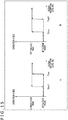
- FIG. 15 depicts diagrams describing switching between the operation modes in the case where different values are used as the detection mode threshold and the communication mode threshold.
- FIG. 15A is a diagram describing switching between the operation modes in the case where a value smaller than a detection mode threshold (first threshold) THon is used as a communication mode threshold (second threshold) THoff.
- first threshold detection mode threshold
- second threshold communication mode threshold
- the operation mode changes to the detection mode.
- the communication mode threshold THoff it is possible to prevent accidental switching of the operation mode from the detection mode to the communication mode due to the reception of a small-level signal such as noise by the receiver 222.
- the level Prx of the modulated signal received by the receiver 122 or 222 drops momentarily for some kind of cause, it is possible to prevent accidental switching of the operation mode from the communication mode to the detection mode.
- FIG. 15B is a diagram describing switching between the operation modes in the case where a value larger than the detection mode threshold (first threshold) THon is used as the communication mode threshold THoff.
- the operation mode changes to the detection mode.
- the communication mode threshold THoff it is possible to reduce power consumption by keeping to a minimum the level of the narrow-band low-level signal sent by the transmitter 121 and at the same time render the response to switching from the detection mode to the communication mode sensitive.
- the operation mode is immediately switched from the communication mode to the detection mode, minimizing radio wave leakage of the modulated signal more positively.
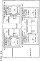
- FIG. 16 is a diagram describing another example of switching between the operation modes.
- the operation mode is switched from the detection mode to the communication mode in response to the narrow-band low-level signal received by the receiver 222 of the communication apparatus 200, a target
- the operation mode can be switched from the detection mode to the communication mode in response to the narrow-band low-level signal received by the receiver 222 of the communication apparatus 200, a target, and the narrow-band low-level signal received by the receiver 122 of the communication apparatus 100, an initiator.
- FIG. 16 is a diagram describing switching between the operation modes that takes place in response to the narrow-band low-level signal received by the receiver 222 and the narrow-band low-level signal received by the receiver 122.
- the waveguide 112 includes one waveguide that is used for both transmission and reception.
- the narrow-band low-level signal sent by the transmitter 121 from the antenna 123 to the waveguide 112 in the detection mode propagates through the waveguide 112 and reaches the outer end face of the waveguide 112.
- the outer end face of the waveguide 112 is in contact with a space.
- nearly all the narrow-band low-level signal is reflected by the outer end face of the waveguide 112 because of the difference in dielectric constant.
- the narrow-band low-level signal reflected by the outer end face of the waveguide 112 propagates back through the waveguide 112 to the side of the antenna 123 and is received by the antenna 123, and eventually by the receiver 122.
- the receiver 122 receives the narrow-band low-level signal that is large in level to some extent.
- the narrow-band low-level signal sent by the transmitter 121 propagates through the waveguides 112 and 212 and reaches and is received by the receiver 222 while maintaining its level to some extent.
- the narrow-band low-level signal is hardly reflected by the outer end face of the waveguide 112.
- a narrow-band low-level signal with a large level is received by the receiver 222.
- a narrow-band low-level signal with an extremely low level is received by the receiver 122 (or a narrow-band low-level signal is not received at all).
- a narrow-band low-level signal having a small level is received by the receiver 222 (or a narrow-band low-level signal is not received at all).
- a narrow-band low-level signal having a large level is received by the receiver 122.
- a narrow-band low-level signal having a large level is received by the receiver 222.
- a narrow-band low-level signal having a small level is received by the receiver 122 (or a narrow-band low-level signal is not received at all).
- whether the level is large or small can be determined by comparison with a threshold determined in advance.
- a millimeter wave band signal was used as a modulated signal (and as a carrier), a signal having a lower frequency or a higher frequency (e.g., light) than a millimeter wave band signal may be used as a modulated signal.
- a system refers to a set of a plurality of components (e.g., apparatuses, modules (parts)), and it does not matter whether or not all the components are accommodated in the same housing. Therefore, a plurality of apparatuses accommodated in different housings and connected via a network and a plurality of modules accommodated in a single housing are both systems.
- components e.g., apparatuses, modules (parts)
Landscapes
- Engineering & Computer Science (AREA)
- Computer Networks & Wireless Communication (AREA)
- Signal Processing (AREA)
- Physics & Mathematics (AREA)
- Electromagnetism (AREA)
- Transceivers (AREA)
Applications Claiming Priority (2)
| Application Number | Priority Date | Filing Date | Title |
|---|---|---|---|
| JP2016006004 | 2016-01-15 | ||
| PCT/JP2017/000013 WO2017122555A1 (ja) | 2016-01-15 | 2017-01-04 | 送信機、送信方法、受信機、及び、受信方法 |
Publications (2)
| Publication Number | Publication Date |
|---|---|
| EP3404840A1 true EP3404840A1 (de) | 2018-11-21 |
| EP3404840A4 EP3404840A4 (de) | 2018-12-26 |
Family
ID=59310996
Family Applications (1)
| Application Number | Title | Priority Date | Filing Date |
|---|---|---|---|
| EP17738310.6A Withdrawn EP3404840A4 (de) | 2016-01-15 | 2017-01-04 | Sender, sendeverfahren, empfänger und empfangsverfahren |
Country Status (4)
| Country | Link |
|---|---|
| US (1) | US10511465B2 (de) |
| EP (1) | EP3404840A4 (de) |
| CN (1) | CN108476034A (de) |
| WO (1) | WO2017122555A1 (de) |
Families Citing this family (1)
| Publication number | Priority date | Publication date | Assignee | Title |
|---|---|---|---|---|
| EP3404840A4 (de) * | 2016-01-15 | 2018-12-26 | Sony Corporation | Sender, sendeverfahren, empfänger und empfangsverfahren |
Family Cites Families (30)
| Publication number | Priority date | Publication date | Assignee | Title |
|---|---|---|---|---|
| US6912651B1 (en) * | 1998-03-31 | 2005-06-28 | Hewlett-Packard Development Company, L.P. | Wireless universal serial bus link for a computer system |
| US7003058B2 (en) * | 2002-02-27 | 2006-02-21 | The Boeing Company | Polarization division duplexing with cross polarization interference canceller |
| US7175249B2 (en) * | 2003-06-06 | 2007-02-13 | Canon Kabushiki Kaisha | Recording apparatus and electronic apparatus |
| US8954719B2 (en) * | 2006-10-24 | 2015-02-10 | Kent E. Dicks | Method for remote provisioning of electronic devices by overlaying an initial image with an updated image |
| JP5216848B2 (ja) * | 2008-03-31 | 2013-06-19 | 京セラ株式会社 | 高周波モジュールおよびその製造方法ならびに該高周波モジュールを備えた送信器、受信器、送受信器およびレーダ装置 |
| US20100296819A1 (en) * | 2008-04-24 | 2010-11-25 | Kahn Joseph M | Optical Receivers and Communication Systems |
| US9191263B2 (en) * | 2008-12-23 | 2015-11-17 | Keyssa, Inc. | Contactless replacement for cabled standards-based interfaces |
| CN102577143B (zh) * | 2009-08-31 | 2016-09-21 | 索尼公司 | 信号发送装置、电子装置和信号发送方法 |
| US8831073B2 (en) * | 2009-08-31 | 2014-09-09 | Sony Corporation | Wireless transmission system, wireless communication device, and wireless communication method |
| JP5375738B2 (ja) | 2010-05-18 | 2013-12-25 | ソニー株式会社 | 信号伝送システム |
| JP5671933B2 (ja) * | 2010-10-18 | 2015-02-18 | ソニー株式会社 | 信号伝送装置 |
| JP5630648B2 (ja) | 2010-11-16 | 2014-11-26 | ソニー株式会社 | 受信装置、受信方法、及び、電子機器 |
| US20130049680A1 (en) * | 2010-12-07 | 2013-02-28 | Panasonic Corporation | Electronic device |
| EP2568626B1 (de) * | 2011-08-18 | 2014-04-02 | Huawei Technologies Co., Ltd. | Bidirektionale optische unterbaugruppe und optische sende-/empfangsvorrichtung |
| JP2013162149A (ja) * | 2012-02-01 | 2013-08-19 | Sony Corp | 伝送方法、及び、伝送システム |
| US9054078B2 (en) * | 2012-02-08 | 2015-06-09 | Sony Corporation | Signal processing device |
| US20150061398A1 (en) * | 2012-09-03 | 2015-03-05 | Kabushiki Kaisha Toshiba | Power Transmitting Apparatus, Power Receiving Apparatus, and Wireless Power Transmission System |
| JP5801268B2 (ja) | 2012-09-03 | 2015-10-28 | 株式会社東芝 | 送電装置、受電装置および無線電力伝送システム |
| CN103891041B (zh) * | 2013-07-04 | 2015-09-30 | 华为技术有限公司 | 滤波器、通信装置及通信系统 |
| HUE039331T2 (hu) * | 2013-12-16 | 2018-12-28 | Grieshaber Vega Kg | Súlyeszköz hullámvezetõhöz, egy szondaeszköz és eljárás súlyeszköz gyártására |
| CN104836208B (zh) * | 2014-02-11 | 2019-02-01 | 快捷半导体(苏州)有限公司 | 标准连接器适配器保护电路和保护方法 |
| JP6138076B2 (ja) * | 2014-03-17 | 2017-05-31 | ソニーセミコンダクタソリューションズ株式会社 | 通信装置、通信システム、及び、通信方法 |
| JP6118286B2 (ja) * | 2014-03-25 | 2017-04-19 | ソニーセミコンダクタソリューションズ株式会社 | 通信装置、及び、制御方法 |
| CN103916179B (zh) * | 2014-03-28 | 2016-09-07 | 武汉光迅科技股份有限公司 | 通过局端光线路终端监控用户端可调激光器波长的方法 |
| US9749043B2 (en) * | 2014-12-09 | 2017-08-29 | Exfo Inc. | Method for referencing an optical power loss measurement system, and associated computer readable memory and OPLM system |
| JP2017004404A (ja) * | 2015-06-15 | 2017-01-05 | ソニー株式会社 | 通信装置、及び、制御方法 |
| EP3404840A4 (de) * | 2016-01-15 | 2018-12-26 | Sony Corporation | Sender, sendeverfahren, empfänger und empfangsverfahren |
| US9977206B2 (en) * | 2016-05-23 | 2018-05-22 | Board Of Supervisors Of Louisiana State University And Agricultural And Mechanical College | Asynchronous distributed optical mutual exclusion interconnect and method |
| US20180279601A1 (en) * | 2017-04-03 | 2018-10-04 | At&T Intellectual Property I, L.P. | Methods, systems and devices to provide physical security to waveguides |
| US10579119B2 (en) * | 2017-05-23 | 2020-03-03 | Cirrus Logic, Inc. | Active charge through of a peripheral device |
-
2017
- 2017-01-04 EP EP17738310.6A patent/EP3404840A4/de not_active Withdrawn
- 2017-01-04 WO PCT/JP2017/000013 patent/WO2017122555A1/ja not_active Ceased
- 2017-01-04 US US16/065,997 patent/US10511465B2/en not_active Expired - Fee Related
- 2017-01-04 CN CN201780005832.4A patent/CN108476034A/zh active Pending
Also Published As
| Publication number | Publication date |
|---|---|
| US10511465B2 (en) | 2019-12-17 |
| CN108476034A (zh) | 2018-08-31 |
| WO2017122555A1 (ja) | 2017-07-20 |
| US20190013975A1 (en) | 2019-01-10 |
| EP3404840A4 (de) | 2018-12-26 |
Similar Documents
| Publication | Publication Date | Title |
|---|---|---|
| US7369811B2 (en) | System and method for sensitivity optimization of RF receiver using adaptive nulling | |
| CN105375935B (zh) | 用于发射接收单元的补偿模块、无线电系统以及用于运行该补偿模块和无线电系统的方法 | |
| US20160036482A1 (en) | Apparatus and method for antenna tuning | |
| KR20170122246A (ko) | 와이어리스 송전 장치, 이물 검출 방법, 충전기 | |
| CN109375176B (zh) | 一种发射机功放模块 | |
| US7696835B2 (en) | Communication system, transmitting device, transmitting method, receiving device, and receiving method | |
| US9351103B2 (en) | Communication device, communication system, and communication method | |
| KR20030010586A (ko) | 광대역 2중 방향성 커플러를 이용하여 실제 전송된 전력을측정하는 방법 및 장치 | |
| JP2015186068A5 (de) | ||
| CN103181099A (zh) | 转发器装置 | |
| US9853686B2 (en) | Vector modulator and transceiver including the same | |
| US20110204043A1 (en) | Radio-frequency heating apparatus | |
| EP3404840A1 (de) | Sender, sendeverfahren, empfänger und empfangsverfahren | |
| CN106028430A (zh) | 天线发射功率的控制方法和装置及射频电路 | |
| US10291383B2 (en) | Communication device and method for wireless signal transmission | |
| US20120062305A1 (en) | Antenna Matching System and Device | |
| CN111211802A (zh) | 可编程衰减器耦合装置、射频电路及电子设备 | |
| JP2018067030A (ja) | Rfidリーダライタおよびrfidシステム | |
| JP2008187227A (ja) | Rfidリーダ | |
| CN100557959C (zh) | 双向放大设备以及具有该设备的半双工通信系统和方法 | |
| CN113765558A (zh) | 一种无线通信装置、天线的检测方法和用户设备 | |
| KR101628359B1 (ko) | Rf 통신장치 및 제어방법 | |
| JP5234947B2 (ja) | 電力検波回路 | |
| CN108734043B (zh) | 一种自适应泄漏对消系统及方法 | |
| WO2018066349A1 (ja) | 通信装置、通信方法、及び、電子機器 |
Legal Events
| Date | Code | Title | Description |
|---|---|---|---|
| STAA | Information on the status of an ep patent application or granted ep patent |
Free format text: STATUS: THE INTERNATIONAL PUBLICATION HAS BEEN MADE |
|
| PUAI | Public reference made under article 153(3) epc to a published international application that has entered the european phase |
Free format text: ORIGINAL CODE: 0009012 |
|
| STAA | Information on the status of an ep patent application or granted ep patent |
Free format text: STATUS: REQUEST FOR EXAMINATION WAS MADE |
|
| 17P | Request for examination filed |
Effective date: 20180808 |
|
| AK | Designated contracting states |
Kind code of ref document: A1 Designated state(s): AL AT BE BG CH CY CZ DE DK EE ES FI FR GB GR HR HU IE IS IT LI LT LU LV MC MK MT NL NO PL PT RO RS SE SI SK SM TR |
|
| AX | Request for extension of the european patent |
Extension state: BA ME |
|
| A4 | Supplementary search report drawn up and despatched |
Effective date: 20181122 |
|
| RIC1 | Information provided on ipc code assigned before grant |
Ipc: H04B 17/29 20150101ALI20181116BHEP Ipc: H01P 3/123 20060101ALI20181116BHEP Ipc: H04B 17/17 20150101ALI20181116BHEP Ipc: H04B 1/40 20150101AFI20181116BHEP |
|
| DAV | Request for validation of the european patent (deleted) | ||
| DAX | Request for extension of the european patent (deleted) | ||
| STAA | Information on the status of an ep patent application or granted ep patent |
Free format text: STATUS: THE APPLICATION HAS BEEN WITHDRAWN |
|
| 18W | Application withdrawn |
Effective date: 20200527 |