EP3405128B1 - Dispositif pour insertion de tige de fusion - Google Patents
Dispositif pour insertion de tige de fusion Download PDFInfo
- Publication number
- EP3405128B1 EP3405128B1 EP17707401.0A EP17707401A EP3405128B1 EP 3405128 B1 EP3405128 B1 EP 3405128B1 EP 17707401 A EP17707401 A EP 17707401A EP 3405128 B1 EP3405128 B1 EP 3405128B1
- Authority
- EP
- European Patent Office
- Prior art keywords
- rod
- fusion
- fusion rod
- guide member
- flexible element
- Prior art date
- Legal status (The legal status is an assumption and is not a legal conclusion. Google has not performed a legal analysis and makes no representation as to the accuracy of the status listed.)
- Active
Links
Images





Classifications
-
- A—HUMAN NECESSITIES
- A61—MEDICAL OR VETERINARY SCIENCE; HYGIENE
- A61B—DIAGNOSIS; SURGERY; IDENTIFICATION
- A61B17/00—Surgical instruments, devices or methods
- A61B17/56—Surgical instruments or methods for treatment of bones or joints; Devices specially adapted therefor
- A61B17/58—Surgical instruments or methods for treatment of bones or joints; Devices specially adapted therefor for osteosynthesis, e.g. bone plates, screws or setting implements
- A61B17/68—Internal fixation devices, including fasteners and spinal fixators, even if a part thereof projects from the skin
- A61B17/70—Spinal positioners or stabilisers, e.g. stabilisers comprising fluid filler in an implant
- A61B17/7074—Tools specially adapted for spinal fixation operations other than for bone removal or filler handling
- A61B17/7083—Tools for guidance or insertion of tethers, rod-to-anchor connectors, rod-to-rod connectors, or longitudinal elements
- A61B17/7085—Tools for guidance or insertion of tethers, rod-to-anchor connectors, rod-to-rod connectors, or longitudinal elements for insertion of a longitudinal element down one or more hollow screw or hook extensions, i.e. at least a part of the element within an extension has a component of movement parallel to the extension's axis
-
- A—HUMAN NECESSITIES
- A61—MEDICAL OR VETERINARY SCIENCE; HYGIENE
- A61B—DIAGNOSIS; SURGERY; IDENTIFICATION
- A61B17/00—Surgical instruments, devices or methods
- A61B17/56—Surgical instruments or methods for treatment of bones or joints; Devices specially adapted therefor
- A61B17/58—Surgical instruments or methods for treatment of bones or joints; Devices specially adapted therefor for osteosynthesis, e.g. bone plates, screws or setting implements
- A61B17/68—Internal fixation devices, including fasteners and spinal fixators, even if a part thereof projects from the skin
- A61B17/70—Spinal positioners or stabilisers, e.g. stabilisers comprising fluid filler in an implant
- A61B17/7001—Screws or hooks combined with longitudinal elements which do not contact vertebrae
- A61B17/7043—Screws or hooks combined with longitudinal elements which do not contact vertebrae with a longitudinal element fixed to one or more transverse elements which connect multiple screws or hooks
-
- A—HUMAN NECESSITIES
- A61—MEDICAL OR VETERINARY SCIENCE; HYGIENE
- A61B—DIAGNOSIS; SURGERY; IDENTIFICATION
- A61B17/00—Surgical instruments, devices or methods
- A61B17/56—Surgical instruments or methods for treatment of bones or joints; Devices specially adapted therefor
- A61B17/58—Surgical instruments or methods for treatment of bones or joints; Devices specially adapted therefor for osteosynthesis, e.g. bone plates, screws or setting implements
- A61B17/68—Internal fixation devices, including fasteners and spinal fixators, even if a part thereof projects from the skin
- A61B17/70—Spinal positioners or stabilisers, e.g. stabilisers comprising fluid filler in an implant
- A61B17/7001—Screws or hooks combined with longitudinal elements which do not contact vertebrae
- A61B17/7002—Longitudinal elements, e.g. rods
- A61B17/7019—Longitudinal elements having flexible parts, or parts connected together, such that after implantation the elements can move relative to each other
- A61B17/7023—Longitudinal elements having flexible parts, or parts connected together, such that after implantation the elements can move relative to each other with a pivot joint
Definitions
- the present invention relates generally to percutaneous fusion surgery, and particularly to fusion rod insertion in percutaneous fusion surgery.
- pedicle screws are inserted through a small incision into the pedicle.
- Each pedicle screw is attached to an extension tube (also called towers).
- the typical tower is a 100-150 mm tube with a quick coupling mechanism at the distal end to allow engagement and disengagement of the tower from the pedicle screw during surgery.
- the towers create a working tunnel from the tulip (polyaxial head) of the screw to the skin surface to facilitate fusion rod insertion and additional hardware.
- the towers enable manipulation of the screws such as distraction, spondylogenic compression correction, and sagittal balance restoration as required to achieve the desired clinical outcome.
- the skin and muscle incision is approximately 20-25 mm long and should optimally be only large enough to accommodate a tower.
- a fusion rod (such as a bent 6 mm diameter titanium rod) is inserted through the longitudinal slots in the towers into the U-shaped pedicle screw head (also referred as tulip or saddle).
- the fusion rod is connected to an insertion tool, which allows easy and secure rod insertion.
- FIGs. 1A and 1B illustrate prior art insertion of a fusion rod 4 through heads of pedicle screws 5.
- the fusion rod 4 is connected to a rotation mechanism 3 located at the distal end of an insertion tool 1.
- the rotation mechanism 3 is operated from the proximal end of the insertion tool 1 and involves a complicated mechanism.
- the fusion rod 4 is inserted through an inner lumen of one of the towers 2.
- the rod 4 is inserted into the tower 2 and is rotated by rotation mechanism 3 until rod 4 is approximately perpendicular to insertion tool 1.
- connection between the insertion tool 1 and the rod 4 is rigid and the rod 4 is pushed into the towers.
- the rod 4 that can be inserted is limited in length because of the limitation of the rotation joint mechanism 3 and the space inside the tower 2.
- US 2012/016423 A1 discloses a system and method for positioning screws and rods to immobilize bones.
- FR 2 924 326 A1 discloses surgical material, including vertebral osteosynthesis material.
- WO 2011/090806 discloses a method and guidewire assembly used in a system.
- US 2014/012321 A1 discloses a spinal stabilization system, method and a surgical kit having a surgical extender apparatus for implanting a surgical screw.
- US 2012/323280 A1 discloses a method for spinal rod insertion including providing a U-shaped hook tool.
- WO 2013/070628 A1 discloses a system that facilitates placement of a rod through receiving portions of screws placed along the spine.
- WO 2007/043044 A1 discloses a spinal prosthesis.
- US 2007/073289 A1 discloses methods and devices for stabilizing adjacent vertebrae in a patient's spinal column.
- US 2006/149230 A1 discloses methods and devices for replacing damaged, injured, diseased or otherwise unhealthy posterior elements.
- the present invention seeks to provide novel apparatus for fusion rod insertion in percutaneous fusion surgery, as is described more in detail hereinbelow.
- the rod is pulled into the tower using a flexible connection, such as wire or strip, rather than pushing it using a rigid connection.
- the fusion rod apparatus easily guides the rod into the longitudinal slot of the tower, thus facilitating fusion rod placement.
- a fusion rod including mounting structures located at different places thereon, and a first flexible element attached to one of the mounting structures and a second flexible element attached to another of the mounting structures, wherein the flexible elements pivotally sit in the sockets of the mounting structures.
- an insertion guide member in accordance with an embodiment of the present invention includes a half-tube with an arcuate guide member that has a distal end that curves and protrudes out of the insertion guide member.
- the arcuate guide member may include a leaf spring.
- the insertion guide member may be inserted in a pedicle screw tower.
- a pair of the insertion guide members may be inserted in pedicle screw towers so that the arcuate guide members form a guiding path for the flexible elements and the fusion rod.
- a rod inserter may be attached to one of the flexible elements, wherein tightening or loosening the flexible element with respect to the rod inserter causes the fusion rod to be perpendicular or not perpendicular with respect to a longitudinal axis of the rod inserter.
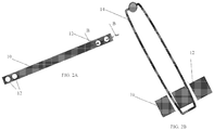
- Fusion rod 10 is a modified rod with mounting structure 12 for mounting thereto a flexible element 14 ( Figs. 2B-2C ), which may be a flexible wire or strip, for example.
- the mounting structure 12 may be holes or prongs or any other suitable structure for passing the flexible element 14 therethrough or for tying or otherwise attaching flexible element 14 thereto, for example.
- mounting structure 12 may be holes drilled 2-5mm from the end of the rod in the area that does not participate in the connection to the pedicle screw nor is fastened by the setscrew of the pedicle attachment.
- the flexible element 14 may pass through the mounting structure 12 so as to form a loop ( Fig. 2B ) or may have a spherical end 16 that pivotally sits in a socket mounting structure 12 ( Fig. 2C ), in which case there is no loop but rather a free, flexible end.
- Flexible elements 14 may be connected to opposite ends of fusion rod 10 (i.e., two flexible elements for one rod). The connection can be done in the operation room or supplied pre-packed. The connection may be done in a manner that allows easy disconnection when the rod is in its final position in the towers. At the end of the fusion installation procedure, the flexible elements 14 may be cut or otherwise removed before tightening the set screw on the fusion rod.
- the insertion guide member 18 may include a half-tube (e.g., the shape of a tube axially cut along its length to form a trough with a U-shaped cross-section) with an arcuate guide member 22 which has a distal end that curves and protrudes out of the insertion guide member 18.
- the arcuate guide member 22 may be a leaf spring or other suitable member.
- the arcuate guide member 22 may optionally pivot about a pivot 24.
- the insertion guide member 18 is inserted in tower 20, which is mounted on a pedicle screw 26.
- FIG. 4A illustrates towers 20 assembled on pedicle screws 26, showing open side (longitudinal) slots 28 of the towers 20. (Rod 10 is shown already installed in the pedicle screws.)
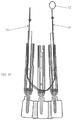
- FIG. 4B and 4C illustrate a pair of insertion guide members 18 installed in towers 20, in which arcuate guide members 22 form a guiding path for the flexible elements and fusion rod, as is now explained.
- the placement of the screws 26 and attachment of the towers 20 may be performed as in a typical percutaneous approach. All the screws 26 connected to towers 20 may be placed in the pedicles.
- the insertion guide members 18 are installed in the caudal and cephalad towers 20 (the two outermost towers in the figures).
- the insertion guide members 18 are inserted into the towers 20 so that the arcuate guide members 22 face the longitudinal slots 28 of the towers 20.
- the arcuate guide members 22 of the caudal and cephalad insertion guide members 18 meet at the middle tower and create a U-shaped slope, which will be a guiding path for the flexible elements and fusion rod.
- a flexible pull strip 30 may be inserted through the guide path.
- One end of the pull strip 30 is attached to a holding element 32, such as a hook loop or clip of some sort.
- the insertion guide members 18 may be removed from the towers 20 at this point, if desired.
- Fig. 5 One end of flexible element 14 may be connected to holding element 32.
- pull strip 30 flexible element 14 is pulled through the guiding path.
- the other end of flexible element 14 is attached to rod 10, so that as flexible element 14 is pulled through the guiding path, rod 10 becomes installed through the tulips of three pedicle screws 26.
- the pull strip 30, together with flexible element 14 attached to rod 10 is pulled back into the cephalad tower 20 and out of the caudal tower 20 (or vice versa) to a position where one of the flexible elements 14 connected to the fusion rod 10 passes through all the towers 20.
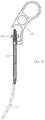
- the flexible element 14 attached to the opposite end of rod 10 is attached to a rod inserter 40, which is now described with reference to Figs. 6A and 6B .
- the rod inserter 40 is an instrument designed to hold and insert the fusion rod 10 into the head of the pedicle screw 26.
- the rod inserter 40 is designed to control the orientation of the fusion rod 10 relative to the inserter 40 to facilitate the rod insertion through the tower.
- the flexible element 14 connected to fusion rod 10 is a 1.5 mm diameter wire.
- the flexible element 14 may be passed through a longitudinal slot 42 in the rod inserter body.
- An end of flexible element 14 may be looped and inserted into a tightening element 44 in the inserter 40 which is located on the proximal end of the inserter 40.
- Rotation of a tightening knob 46 pulls the tightening element 44 further proximally thus tightening the rod 10 against the inserter body.
- the rod 10 is perpendicular to the inserter 40 and provides a rigid connection ( Fig. 7A ).
- rod 10 When the flexible element 14 is not fully tightened, rod 10 can shift to a position parallel to the inserter body ( Fig. 7C ) to allow insertion to the tower. By tightening and releasing the tension in the flexible element 14 the position of the rod can be changed to control the rod insertion.
- the rod 10 can be pushed and controlled by the inserter 40 and pulled to assist in placing the rod 10 by the flexible element 14 connected to the free end of the rod 10.
- the wire/strip 30 can be used as a guide to reattach the inserter or other tool during the procedure.
- the flexible element 14 can be cut at the end of the procedure and pulled out.
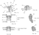
- FIG. 8A-8F illustrate a spinal prosthesis 80, not claimed.
- the spinal prosthesis 80 may include a first spinal prosthetic member 82, which may be attached to a first spinal structure, such as but not limited to, a vertebra (e.g., L3 or L4), and a second spinal prosthetic member 84, which may be attached to a second spinal structure, such as but not limited to, a vertebra (e.g., L4 or L5).
- a first spinal prosthetic member 82 which may be attached to a first spinal structure, such as but not limited to, a vertebra (e.g., L3 or L4)
- a second spinal prosthetic member 84 which may be attached to a second spinal structure, such as but not limited to, a vertebra (e.g., L4 or L5).
- the first and second spinal prosthetic members 82 and 84 may respectively include attachment members 86 and 88, such as but not limited to, a pair of rounded prongs that can be fastened to polyaxial pedicle screws,
- the first and second spinal prosthetic members 82 and 84 may each include central articulating members 90, such as elastomeric cushions or bearings (e.g., roller bearings) that allow first and second spinal prosthetic members 82 and 84 to articulate in more than one degree of freedom.
- the elastomeric cushions or bearings may permit the first and second spinal prosthetic members 82 and 84 to rotate about and translate along respective rotation axes 92 and 94.
- Other degrees of movement are also possible such as azimuthal or bending modes of motion.
- the central articulating members 90 may be housed in a common housing 96.
- the first and second spinal prosthetic members 82 and 84 can be pivoted with respect to each other about rotation axes 92 and 94 (parallel to the prongs) to expand or stretch outwards to an extended position.
- the first and second spinal prosthetic members 82 and 84 can be pivoted with respect to each other to contract or collapse to a contracted position with a narrow height (e.g., 9 mm).
- the spinal prosthesis 80 can be installed in a small incision in the contracted position for a minimal invasive approach, and then after installation expanded to the expanded position to match any 1PD inter-pedicular distance between two vertebrae (e.g., 38 mm).
- the center of rotation of the implant can be adjusted without changing the screws location or high.
- the center of rotation of the implant can be adjusted to coincide with the center of rotation of an artificial disc so both implants can work in unison.
- central articulating members 90 may include a pawl or ratchet device to lock the first and second spinal prosthetic members 82 and 84 at any desired angular orientation.
Landscapes
- Health & Medical Sciences (AREA)
- Orthopedic Medicine & Surgery (AREA)
- Neurology (AREA)
- Life Sciences & Earth Sciences (AREA)
- Surgery (AREA)
- Heart & Thoracic Surgery (AREA)
- Engineering & Computer Science (AREA)
- Biomedical Technology (AREA)
- Nuclear Medicine, Radiotherapy & Molecular Imaging (AREA)
- Medical Informatics (AREA)
- Molecular Biology (AREA)
- Animal Behavior & Ethology (AREA)
- General Health & Medical Sciences (AREA)
- Public Health (AREA)
- Veterinary Medicine (AREA)
- Surgical Instruments (AREA)
- Prostheses (AREA)
- Lining Or Joining Of Plastics Or The Like (AREA)
Claims (6)
- Appareil à tige de fusion, comprenant :une tige de fusion (10) comprenant des structures de montage (12) disposées à différents emplacements sur celle-ci ;un premier élément flexible (14) fixé sur une desdites structures de montage (12), et un deuxième élément flexible (14) fixé sur une autre desdites structures de montage (12), et dans lequel lesdits éléments flexibles (14) reposent de manière pivotante dans des douilles desdites structures de montage (12).
- Appareil à tige de fusion selon la revendication 1, comprenant en outre un élément de guidage d'insertion (18) qui comprend un demi-tube avec un élément de guidage arqué (22) qui comporte une extrémité distale qui est courbée et fait saillie hors dudit élément de guidage d'insertion (18).
- Appareil à tige de fusion selon la revendication 2, dans lequel ledit élément de guidage arqué (22) comprend un ressort à lames.
- Appareil à tige de fusion selon la revendication 2, dans lequel ledit élément de guidage d'insertion (18) est inséré dans une tour à vis pédiculaire (20).
- Appareil à tige de fusion selon la revendication 2, dans lequel une paire desdits éléments de guidage d'insertion (18) est insérée dans des tours à vis pédiculaire (20), de sorte que lesdits éléments de guidage arqués (22) forment un trajet de guidage pour lesdits éléments flexibles (14) et ladite tige de fusion (10).
- Appareil à tige de fusion selon la revendication 1, comprenant en outre un dispositif d'insertion de tige (40) fixé sur l'un desdits éléments flexibles (14), dans lequel le serrage ou le desserrage dudit élément flexible (14) par rapport audit dispositif d'insertion de la tige (40) entraîne ladite tige de fusion (10) à être perpendiculaire ou non perpendiculaire à un axe longitudinal dudit dispositif d'insertion de la tige (40).
Priority Applications (1)
| Application Number | Priority Date | Filing Date | Title |
|---|---|---|---|
| EP21209422.1A EP3977950B1 (fr) | 2016-01-18 | 2017-01-12 | Prothèse vertébrale |
Applications Claiming Priority (2)
| Application Number | Priority Date | Filing Date | Title |
|---|---|---|---|
| US201662279894P | 2016-01-18 | 2016-01-18 | |
| PCT/IB2017/050164 WO2017125837A2 (fr) | 2016-01-18 | 2017-01-12 | Insertion de tige de fusion en chirurgie de fusion percutanée |
Related Child Applications (1)
| Application Number | Title | Priority Date | Filing Date |
|---|---|---|---|
| EP21209422.1A Division EP3977950B1 (fr) | 2016-01-18 | 2017-01-12 | Prothèse vertébrale |
Publications (2)
| Publication Number | Publication Date |
|---|---|
| EP3405128A2 EP3405128A2 (fr) | 2018-11-28 |
| EP3405128B1 true EP3405128B1 (fr) | 2021-11-24 |
Family
ID=58162964
Family Applications (2)
| Application Number | Title | Priority Date | Filing Date |
|---|---|---|---|
| EP17707401.0A Active EP3405128B1 (fr) | 2016-01-18 | 2017-01-12 | Dispositif pour insertion de tige de fusion |
| EP21209422.1A Active EP3977950B1 (fr) | 2016-01-18 | 2017-01-12 | Prothèse vertébrale |
Family Applications After (1)
| Application Number | Title | Priority Date | Filing Date |
|---|---|---|---|
| EP21209422.1A Active EP3977950B1 (fr) | 2016-01-18 | 2017-01-12 | Prothèse vertébrale |
Country Status (3)
| Country | Link |
|---|---|
| US (2) | US20210220025A1 (fr) |
| EP (2) | EP3405128B1 (fr) |
| WO (1) | WO2017125837A2 (fr) |
Families Citing this family (1)
| Publication number | Priority date | Publication date | Assignee | Title |
|---|---|---|---|---|
| CN112043366A (zh) * | 2020-09-17 | 2020-12-08 | 山东航维骨科医疗器械股份有限公司 | 一种微创脊柱棒牵引器 |
Family Cites Families (10)
| Publication number | Priority date | Publication date | Assignee | Title |
|---|---|---|---|---|
| US7766940B2 (en) * | 2004-12-30 | 2010-08-03 | Depuy Spine, Inc. | Posterior stabilization system |
| US8163024B2 (en) * | 2005-09-14 | 2012-04-24 | Premia Spine Ltd. | Adjustable spinal prostheses |
| US7879074B2 (en) * | 2005-09-27 | 2011-02-01 | Depuy Spine, Inc. | Posterior dynamic stabilization systems and methods |
| US7604652B2 (en) * | 2005-10-11 | 2009-10-20 | Impliant Ltd. | Spinal prosthesis |
| FR2924326B1 (fr) * | 2007-11-30 | 2010-12-10 | Medicrea International | Materiel chirurgical, notamment materiel d'osteosynthese vertebrale |
| CA2739431C (fr) * | 2008-10-01 | 2016-12-06 | Sherwin Hua | Systeme et procede de stabilisation de vertebres spinales par vis pediculaires guidees par fils |
| EP2742885B1 (fr) * | 2008-10-23 | 2018-11-21 | Alphatec Spine, Inc. | Systèmes pour fixation spinale |
| WO2011090806A1 (fr) * | 2010-01-22 | 2011-07-28 | Javier Garcia-Bengochea | Méthode et appareil utilisés à des fins de fixation rachidienne et impliquant des techniques chirurgicales les moins invasives possibles |
| US8968319B2 (en) * | 2011-06-20 | 2015-03-03 | Spinefrontier, Inc | Methods, tools and devices for spinal fixation |
| US9526535B2 (en) * | 2011-11-07 | 2016-12-27 | Morgan Packard Lorio | Methods and apparatuses for delivering a rod to a plurality of pedicle screws |
-
2017
- 2017-01-12 US US16/070,283 patent/US20210220025A1/en not_active Abandoned
- 2017-01-12 EP EP17707401.0A patent/EP3405128B1/fr active Active
- 2017-01-12 EP EP21209422.1A patent/EP3977950B1/fr active Active
- 2017-01-12 WO PCT/IB2017/050164 patent/WO2017125837A2/fr not_active Ceased
-
2022
- 2022-08-03 US US17/879,939 patent/US12539149B2/en active Active
Also Published As
| Publication number | Publication date |
|---|---|
| US20210220025A1 (en) | 2021-07-22 |
| EP3977950C0 (fr) | 2025-12-17 |
| US12539149B2 (en) | 2026-02-03 |
| US20220370102A1 (en) | 2022-11-24 |
| WO2017125837A2 (fr) | 2017-07-27 |
| WO2017125837A3 (fr) | 2017-10-12 |
| EP3405128A2 (fr) | 2018-11-28 |
| EP3977950B1 (fr) | 2025-12-17 |
| EP3977950A1 (fr) | 2022-04-06 |
Similar Documents
| Publication | Publication Date | Title |
|---|---|---|
| US12396765B2 (en) | Instruments and methods for tensioning a spinal tether | |
| US20240268868A1 (en) | Lateral mass fixation implant | |
| US8226690B2 (en) | Systems and methods for stabilization of bone structures | |
| US10779959B2 (en) | Surgical instrument for implant insertion | |
| US20070083210A1 (en) | Apparatus and method for minimally invasive spine surgery | |
| US20070239159A1 (en) | Systems and methods for stabilization of bone structures | |
| JP7137736B2 (ja) | 連接ロッド挿入体 | |
| CN102014776A (zh) | 用于插入柔性脊柱稳定元件的系统和方法 | |
| US12539149B2 (en) | Fusion rod insertion in percutaneous fusion surgery |
Legal Events
| Date | Code | Title | Description |
|---|---|---|---|
| STAA | Information on the status of an ep patent application or granted ep patent |
Free format text: STATUS: UNKNOWN |
|
| STAA | Information on the status of an ep patent application or granted ep patent |
Free format text: STATUS: THE INTERNATIONAL PUBLICATION HAS BEEN MADE |
|
| PUAI | Public reference made under article 153(3) epc to a published international application that has entered the european phase |
Free format text: ORIGINAL CODE: 0009012 |
|
| STAA | Information on the status of an ep patent application or granted ep patent |
Free format text: STATUS: REQUEST FOR EXAMINATION WAS MADE |
|
| 17P | Request for examination filed |
Effective date: 20180801 |
|
| AK | Designated contracting states |
Kind code of ref document: A2 Designated state(s): AL AT BE BG CH CY CZ DE DK EE ES FI FR GB GR HR HU IE IS IT LI LT LU LV MC MK MT NL NO PL PT RO RS SE SI SK SM TR |
|
| AX | Request for extension of the european patent |
Extension state: BA ME |
|
| DAV | Request for validation of the european patent (deleted) | ||
| DAX | Request for extension of the european patent (deleted) | ||
| GRAP | Despatch of communication of intention to grant a patent |
Free format text: ORIGINAL CODE: EPIDOSNIGR1 |
|
| STAA | Information on the status of an ep patent application or granted ep patent |
Free format text: STATUS: GRANT OF PATENT IS INTENDED |
|
| INTG | Intention to grant announced |
Effective date: 20210909 |
|
| GRAS | Grant fee paid |
Free format text: ORIGINAL CODE: EPIDOSNIGR3 |
|
| GRAA | (expected) grant |
Free format text: ORIGINAL CODE: 0009210 |
|
| STAA | Information on the status of an ep patent application or granted ep patent |
Free format text: STATUS: THE PATENT HAS BEEN GRANTED |
|
| AK | Designated contracting states |
Kind code of ref document: B1 Designated state(s): AL AT BE BG CH CY CZ DE DK EE ES FI FR GB GR HR HU IE IS IT LI LT LU LV MC MK MT NL NO PL PT RO RS SE SI SK SM TR |
|
| REG | Reference to a national code |
Ref country code: GB Ref legal event code: FG4D |
|
| REG | Reference to a national code |
Ref country code: AT Ref legal event code: REF Ref document number: 1449254 Country of ref document: AT Kind code of ref document: T Effective date: 20211215 |
|
| REG | Reference to a national code |
Ref country code: DE Ref legal event code: R096 Ref document number: 602017049739 Country of ref document: DE |
|
| REG | Reference to a national code |
Ref country code: IE Ref legal event code: FG4D |
|
| REG | Reference to a national code |
Ref country code: LT Ref legal event code: MG9D |
|
| REG | Reference to a national code |
Ref country code: NL Ref legal event code: MP Effective date: 20211124 |
|
| REG | Reference to a national code |
Ref country code: AT Ref legal event code: MK05 Ref document number: 1449254 Country of ref document: AT Kind code of ref document: T Effective date: 20211124 |
|
| PG25 | Lapsed in a contracting state [announced via postgrant information from national office to epo] |
Ref country code: RS Free format text: LAPSE BECAUSE OF FAILURE TO SUBMIT A TRANSLATION OF THE DESCRIPTION OR TO PAY THE FEE WITHIN THE PRESCRIBED TIME-LIMIT Effective date: 20211124 Ref country code: LT Free format text: LAPSE BECAUSE OF FAILURE TO SUBMIT A TRANSLATION OF THE DESCRIPTION OR TO PAY THE FEE WITHIN THE PRESCRIBED TIME-LIMIT Effective date: 20211124 Ref country code: FI Free format text: LAPSE BECAUSE OF FAILURE TO SUBMIT A TRANSLATION OF THE DESCRIPTION OR TO PAY THE FEE WITHIN THE PRESCRIBED TIME-LIMIT Effective date: 20211124 Ref country code: BG Free format text: LAPSE BECAUSE OF FAILURE TO SUBMIT A TRANSLATION OF THE DESCRIPTION OR TO PAY THE FEE WITHIN THE PRESCRIBED TIME-LIMIT Effective date: 20220224 Ref country code: AT Free format text: LAPSE BECAUSE OF FAILURE TO SUBMIT A TRANSLATION OF THE DESCRIPTION OR TO PAY THE FEE WITHIN THE PRESCRIBED TIME-LIMIT Effective date: 20211124 |
|
| PG25 | Lapsed in a contracting state [announced via postgrant information from national office to epo] |
Ref country code: IS Free format text: LAPSE BECAUSE OF FAILURE TO SUBMIT A TRANSLATION OF THE DESCRIPTION OR TO PAY THE FEE WITHIN THE PRESCRIBED TIME-LIMIT Effective date: 20220324 Ref country code: SE Free format text: LAPSE BECAUSE OF FAILURE TO SUBMIT A TRANSLATION OF THE DESCRIPTION OR TO PAY THE FEE WITHIN THE PRESCRIBED TIME-LIMIT Effective date: 20211124 Ref country code: PT Free format text: LAPSE BECAUSE OF FAILURE TO SUBMIT A TRANSLATION OF THE DESCRIPTION OR TO PAY THE FEE WITHIN THE PRESCRIBED TIME-LIMIT Effective date: 20220324 Ref country code: PL Free format text: LAPSE BECAUSE OF FAILURE TO SUBMIT A TRANSLATION OF THE DESCRIPTION OR TO PAY THE FEE WITHIN THE PRESCRIBED TIME-LIMIT Effective date: 20211124 Ref country code: NO Free format text: LAPSE BECAUSE OF FAILURE TO SUBMIT A TRANSLATION OF THE DESCRIPTION OR TO PAY THE FEE WITHIN THE PRESCRIBED TIME-LIMIT Effective date: 20220224 Ref country code: NL Free format text: LAPSE BECAUSE OF FAILURE TO SUBMIT A TRANSLATION OF THE DESCRIPTION OR TO PAY THE FEE WITHIN THE PRESCRIBED TIME-LIMIT Effective date: 20211124 Ref country code: LV Free format text: LAPSE BECAUSE OF FAILURE TO SUBMIT A TRANSLATION OF THE DESCRIPTION OR TO PAY THE FEE WITHIN THE PRESCRIBED TIME-LIMIT Effective date: 20211124 Ref country code: HR Free format text: LAPSE BECAUSE OF FAILURE TO SUBMIT A TRANSLATION OF THE DESCRIPTION OR TO PAY THE FEE WITHIN THE PRESCRIBED TIME-LIMIT Effective date: 20211124 Ref country code: GR Free format text: LAPSE BECAUSE OF FAILURE TO SUBMIT A TRANSLATION OF THE DESCRIPTION OR TO PAY THE FEE WITHIN THE PRESCRIBED TIME-LIMIT Effective date: 20220225 Ref country code: ES Free format text: LAPSE BECAUSE OF FAILURE TO SUBMIT A TRANSLATION OF THE DESCRIPTION OR TO PAY THE FEE WITHIN THE PRESCRIBED TIME-LIMIT Effective date: 20211124 |
|
| PG25 | Lapsed in a contracting state [announced via postgrant information from national office to epo] |
Ref country code: SM Free format text: LAPSE BECAUSE OF FAILURE TO SUBMIT A TRANSLATION OF THE DESCRIPTION OR TO PAY THE FEE WITHIN THE PRESCRIBED TIME-LIMIT Effective date: 20211124 Ref country code: SK Free format text: LAPSE BECAUSE OF FAILURE TO SUBMIT A TRANSLATION OF THE DESCRIPTION OR TO PAY THE FEE WITHIN THE PRESCRIBED TIME-LIMIT Effective date: 20211124 Ref country code: RO Free format text: LAPSE BECAUSE OF FAILURE TO SUBMIT A TRANSLATION OF THE DESCRIPTION OR TO PAY THE FEE WITHIN THE PRESCRIBED TIME-LIMIT Effective date: 20211124 Ref country code: EE Free format text: LAPSE BECAUSE OF FAILURE TO SUBMIT A TRANSLATION OF THE DESCRIPTION OR TO PAY THE FEE WITHIN THE PRESCRIBED TIME-LIMIT Effective date: 20211124 Ref country code: DK Free format text: LAPSE BECAUSE OF FAILURE TO SUBMIT A TRANSLATION OF THE DESCRIPTION OR TO PAY THE FEE WITHIN THE PRESCRIBED TIME-LIMIT Effective date: 20211124 Ref country code: CZ Free format text: LAPSE BECAUSE OF FAILURE TO SUBMIT A TRANSLATION OF THE DESCRIPTION OR TO PAY THE FEE WITHIN THE PRESCRIBED TIME-LIMIT Effective date: 20211124 |
|
| REG | Reference to a national code |
Ref country code: DE Ref legal event code: R097 Ref document number: 602017049739 Country of ref document: DE |
|
| PG25 | Lapsed in a contracting state [announced via postgrant information from national office to epo] |
Ref country code: MC Free format text: LAPSE BECAUSE OF FAILURE TO SUBMIT A TRANSLATION OF THE DESCRIPTION OR TO PAY THE FEE WITHIN THE PRESCRIBED TIME-LIMIT Effective date: 20211124 |
|
| PLBE | No opposition filed within time limit |
Free format text: ORIGINAL CODE: 0009261 |
|
| STAA | Information on the status of an ep patent application or granted ep patent |
Free format text: STATUS: NO OPPOSITION FILED WITHIN TIME LIMIT |
|
| REG | Reference to a national code |
Ref country code: BE Ref legal event code: MM Effective date: 20220131 |
|
| PG25 | Lapsed in a contracting state [announced via postgrant information from national office to epo] |
Ref country code: LU Free format text: LAPSE BECAUSE OF NON-PAYMENT OF DUE FEES Effective date: 20220112 Ref country code: AL Free format text: LAPSE BECAUSE OF FAILURE TO SUBMIT A TRANSLATION OF THE DESCRIPTION OR TO PAY THE FEE WITHIN THE PRESCRIBED TIME-LIMIT Effective date: 20211124 |
|
| 26N | No opposition filed |
Effective date: 20220825 |
|
| PG25 | Lapsed in a contracting state [announced via postgrant information from national office to epo] |
Ref country code: SI Free format text: LAPSE BECAUSE OF FAILURE TO SUBMIT A TRANSLATION OF THE DESCRIPTION OR TO PAY THE FEE WITHIN THE PRESCRIBED TIME-LIMIT Effective date: 20211124 Ref country code: BE Free format text: LAPSE BECAUSE OF NON-PAYMENT OF DUE FEES Effective date: 20220131 |
|
| PG25 | Lapsed in a contracting state [announced via postgrant information from national office to epo] |
Ref country code: IE Free format text: LAPSE BECAUSE OF NON-PAYMENT OF DUE FEES Effective date: 20220112 |
|
| PG25 | Lapsed in a contracting state [announced via postgrant information from national office to epo] |
Ref country code: IT Free format text: LAPSE BECAUSE OF FAILURE TO SUBMIT A TRANSLATION OF THE DESCRIPTION OR TO PAY THE FEE WITHIN THE PRESCRIBED TIME-LIMIT Effective date: 20211124 |
|
| PG25 | Lapsed in a contracting state [announced via postgrant information from national office to epo] |
Ref country code: HU Free format text: LAPSE BECAUSE OF FAILURE TO SUBMIT A TRANSLATION OF THE DESCRIPTION OR TO PAY THE FEE WITHIN THE PRESCRIBED TIME-LIMIT; INVALID AB INITIO Effective date: 20170112 |
|
| PG25 | Lapsed in a contracting state [announced via postgrant information from national office to epo] |
Ref country code: MK Free format text: LAPSE BECAUSE OF FAILURE TO SUBMIT A TRANSLATION OF THE DESCRIPTION OR TO PAY THE FEE WITHIN THE PRESCRIBED TIME-LIMIT Effective date: 20211124 Ref country code: CY Free format text: LAPSE BECAUSE OF FAILURE TO SUBMIT A TRANSLATION OF THE DESCRIPTION OR TO PAY THE FEE WITHIN THE PRESCRIBED TIME-LIMIT Effective date: 20211124 |
|
| PG25 | Lapsed in a contracting state [announced via postgrant information from national office to epo] |
Ref country code: TR Free format text: LAPSE BECAUSE OF FAILURE TO SUBMIT A TRANSLATION OF THE DESCRIPTION OR TO PAY THE FEE WITHIN THE PRESCRIBED TIME-LIMIT Effective date: 20211124 |
|
| PG25 | Lapsed in a contracting state [announced via postgrant information from national office to epo] |
Ref country code: MT Free format text: LAPSE BECAUSE OF FAILURE TO SUBMIT A TRANSLATION OF THE DESCRIPTION OR TO PAY THE FEE WITHIN THE PRESCRIBED TIME-LIMIT Effective date: 20211124 |
|
| PGFP | Annual fee paid to national office [announced via postgrant information from national office to epo] |
Ref country code: GB Payment date: 20251204 Year of fee payment: 10 |
|
| PGFP | Annual fee paid to national office [announced via postgrant information from national office to epo] |
Ref country code: FR Payment date: 20251208 Year of fee payment: 10 |
|
| REG | Reference to a national code |
Ref country code: CH Ref legal event code: U11 Free format text: ST27 STATUS EVENT CODE: U-0-0-U10-U11 (AS PROVIDED BY THE NATIONAL OFFICE) Effective date: 20260201 |
|
| PGFP | Annual fee paid to national office [announced via postgrant information from national office to epo] |
Ref country code: DE Payment date: 20251203 Year of fee payment: 10 |
|
| PGFP | Annual fee paid to national office [announced via postgrant information from national office to epo] |
Ref country code: CH Payment date: 20260201 Year of fee payment: 10 |