EP3405129B1 - Wirbelsäulenkorrektursystem - Google Patents
Wirbelsäulenkorrektursystem Download PDFInfo
- Publication number
- EP3405129B1 EP3405129B1 EP17741917.3A EP17741917A EP3405129B1 EP 3405129 B1 EP3405129 B1 EP 3405129B1 EP 17741917 A EP17741917 A EP 17741917A EP 3405129 B1 EP3405129 B1 EP 3405129B1
- Authority
- EP
- European Patent Office
- Prior art keywords
- tensioning
- fulcrum
- tensioning member
- tensioner device
- spinal
- Prior art date
- Legal status (The legal status is an assumption and is not a legal conclusion. Google has not performed a legal analysis and makes no representation as to the accuracy of the status listed.)
- Active
Links
Images






Classifications
-
- A—HUMAN NECESSITIES
- A61—MEDICAL OR VETERINARY SCIENCE; HYGIENE
- A61B—DIAGNOSIS; SURGERY; IDENTIFICATION
- A61B17/00—Surgical instruments, devices or methods
- A61B17/56—Surgical instruments or methods for treatment of bones or joints; Devices specially adapted therefor
- A61B17/58—Surgical instruments or methods for treatment of bones or joints; Devices specially adapted therefor for osteosynthesis, e.g. bone plates, screws or setting implements
- A61B17/68—Internal fixation devices, including fasteners and spinal fixators, even if a part thereof projects from the skin
- A61B17/84—Fasteners therefor or fasteners being internal fixation devices
- A61B17/86—Pins or screws or threaded wires; nuts therefor
- A61B17/8625—Shanks, i.e. parts contacting bone tissue
-
- A—HUMAN NECESSITIES
- A61—MEDICAL OR VETERINARY SCIENCE; HYGIENE
- A61B—DIAGNOSIS; SURGERY; IDENTIFICATION
- A61B17/00—Surgical instruments, devices or methods
- A61B17/56—Surgical instruments or methods for treatment of bones or joints; Devices specially adapted therefor
- A61B17/58—Surgical instruments or methods for treatment of bones or joints; Devices specially adapted therefor for osteosynthesis, e.g. bone plates, screws or setting implements
- A61B17/68—Internal fixation devices, including fasteners and spinal fixators, even if a part thereof projects from the skin
- A61B17/70—Spinal positioners or stabilisers, e.g. stabilisers comprising fluid filler in an implant
- A61B17/7001—Screws or hooks combined with longitudinal elements which do not contact vertebrae
- A61B17/7002—Longitudinal elements, e.g. rods
- A61B17/7019—Longitudinal elements having flexible parts, or parts connected together, such that after implantation the elements can move relative to each other
- A61B17/7022—Tethers, i.e. longitudinal elements capable of transmitting tension only, e.g. straps, sutures or cables
-
- A—HUMAN NECESSITIES
- A61—MEDICAL OR VETERINARY SCIENCE; HYGIENE
- A61B—DIAGNOSIS; SURGERY; IDENTIFICATION
- A61B17/00—Surgical instruments, devices or methods
- A61B17/56—Surgical instruments or methods for treatment of bones or joints; Devices specially adapted therefor
- A61B17/58—Surgical instruments or methods for treatment of bones or joints; Devices specially adapted therefor for osteosynthesis, e.g. bone plates, screws or setting implements
- A61B17/68—Internal fixation devices, including fasteners and spinal fixators, even if a part thereof projects from the skin
- A61B17/70—Spinal positioners or stabilisers, e.g. stabilisers comprising fluid filler in an implant
-
- A—HUMAN NECESSITIES
- A61—MEDICAL OR VETERINARY SCIENCE; HYGIENE
- A61B—DIAGNOSIS; SURGERY; IDENTIFICATION
- A61B17/00—Surgical instruments, devices or methods
- A61B17/56—Surgical instruments or methods for treatment of bones or joints; Devices specially adapted therefor
- A61B17/58—Surgical instruments or methods for treatment of bones or joints; Devices specially adapted therefor for osteosynthesis, e.g. bone plates, screws or setting implements
- A61B17/68—Internal fixation devices, including fasteners and spinal fixators, even if a part thereof projects from the skin
- A61B17/70—Spinal positioners or stabilisers, e.g. stabilisers comprising fluid filler in an implant
- A61B17/7001—Screws or hooks combined with longitudinal elements which do not contact vertebrae
- A61B17/7002—Longitudinal elements, e.g. rods
- A61B17/7019—Longitudinal elements having flexible parts, or parts connected together, such that after implantation the elements can move relative to each other
- A61B17/7031—Longitudinal elements having flexible parts, or parts connected together, such that after implantation the elements can move relative to each other made wholly or partly of flexible material
-
- A—HUMAN NECESSITIES
- A61—MEDICAL OR VETERINARY SCIENCE; HYGIENE
- A61B—DIAGNOSIS; SURGERY; IDENTIFICATION
- A61B17/00—Surgical instruments, devices or methods
- A61B17/56—Surgical instruments or methods for treatment of bones or joints; Devices specially adapted therefor
- A61B17/58—Surgical instruments or methods for treatment of bones or joints; Devices specially adapted therefor for osteosynthesis, e.g. bone plates, screws or setting implements
- A61B17/68—Internal fixation devices, including fasteners and spinal fixators, even if a part thereof projects from the skin
- A61B17/70—Spinal positioners or stabilisers, e.g. stabilisers comprising fluid filler in an implant
- A61B17/7001—Screws or hooks combined with longitudinal elements which do not contact vertebrae
- A61B17/7032—Screws or hooks with U-shaped head or back through which longitudinal rods pass
-
- A—HUMAN NECESSITIES
- A61—MEDICAL OR VETERINARY SCIENCE; HYGIENE
- A61B—DIAGNOSIS; SURGERY; IDENTIFICATION
- A61B17/00—Surgical instruments, devices or methods
- A61B17/56—Surgical instruments or methods for treatment of bones or joints; Devices specially adapted therefor
- A61B17/58—Surgical instruments or methods for treatment of bones or joints; Devices specially adapted therefor for osteosynthesis, e.g. bone plates, screws or setting implements
- A61B17/88—Osteosynthesis instruments; Methods or means for implanting or extracting internal or external fixation devices
- A61B17/8869—Tensioning devices
-
- A—HUMAN NECESSITIES
- A61—MEDICAL OR VETERINARY SCIENCE; HYGIENE
- A61B—DIAGNOSIS; SURGERY; IDENTIFICATION
- A61B17/00—Surgical instruments, devices or methods
- A61B17/56—Surgical instruments or methods for treatment of bones or joints; Devices specially adapted therefor
- A61B17/58—Surgical instruments or methods for treatment of bones or joints; Devices specially adapted therefor for osteosynthesis, e.g. bone plates, screws or setting implements
- A61B17/68—Internal fixation devices, including fasteners and spinal fixators, even if a part thereof projects from the skin
- A61B17/84—Fasteners therefor or fasteners being internal fixation devices
- A61B17/842—Flexible wires, bands or straps
-
- A—HUMAN NECESSITIES
- A61—MEDICAL OR VETERINARY SCIENCE; HYGIENE
- A61B—DIAGNOSIS; SURGERY; IDENTIFICATION
- A61B17/00—Surgical instruments, devices or methods
- A61B17/04—Surgical instruments, devices or methods for suturing wounds; Holders or packages for needles or suture materials
- A61B17/0401—Suture anchors, buttons or pledgets, i.e. means for attaching sutures to bone, cartilage or soft tissue; Instruments for applying or removing suture anchors
- A61B2017/0409—Instruments for applying suture anchors
-
- A—HUMAN NECESSITIES
- A61—MEDICAL OR VETERINARY SCIENCE; HYGIENE
- A61B—DIAGNOSIS; SURGERY; IDENTIFICATION
- A61B17/00—Surgical instruments, devices or methods
- A61B17/04—Surgical instruments, devices or methods for suturing wounds; Holders or packages for needles or suture materials
- A61B17/0401—Suture anchors, buttons or pledgets, i.e. means for attaching sutures to bone, cartilage or soft tissue; Instruments for applying or removing suture anchors
- A61B2017/0414—Suture anchors, buttons or pledgets, i.e. means for attaching sutures to bone, cartilage or soft tissue; Instruments for applying or removing suture anchors having a suture-receiving opening, e.g. lateral opening
-
- A—HUMAN NECESSITIES
- A61—MEDICAL OR VETERINARY SCIENCE; HYGIENE
- A61B—DIAGNOSIS; SURGERY; IDENTIFICATION
- A61B17/00—Surgical instruments, devices or methods
- A61B17/04—Surgical instruments, devices or methods for suturing wounds; Holders or packages for needles or suture materials
- A61B17/0401—Suture anchors, buttons or pledgets, i.e. means for attaching sutures to bone, cartilage or soft tissue; Instruments for applying or removing suture anchors
- A61B2017/044—Suture anchors, buttons or pledgets, i.e. means for attaching sutures to bone, cartilage or soft tissue; Instruments for applying or removing suture anchors with a threaded shaft, e.g. screws
-
- A—HUMAN NECESSITIES
- A61—MEDICAL OR VETERINARY SCIENCE; HYGIENE
- A61B—DIAGNOSIS; SURGERY; IDENTIFICATION
- A61B17/00—Surgical instruments, devices or methods
- A61B17/04—Surgical instruments, devices or methods for suturing wounds; Holders or packages for needles or suture materials
- A61B17/0401—Suture anchors, buttons or pledgets, i.e. means for attaching sutures to bone, cartilage or soft tissue; Instruments for applying or removing suture anchors
- A61B2017/0446—Means for attaching and blocking the suture in the suture anchor
- A61B2017/0448—Additional elements on or within the anchor
-
- A—HUMAN NECESSITIES
- A61—MEDICAL OR VETERINARY SCIENCE; HYGIENE
- A61B—DIAGNOSIS; SURGERY; IDENTIFICATION
- A61B17/00—Surgical instruments, devices or methods
- A61B17/04—Surgical instruments, devices or methods for suturing wounds; Holders or packages for needles or suture materials
- A61B2017/0496—Surgical instruments, devices or methods for suturing wounds; Holders or packages for needles or suture materials for tensioning sutures
Definitions
- the present disclosure relates to a spinal deformity correction device and, more particularly, to a spinal correction system and methods for securing a spinal deformity correction device on a spine.
- the spine is made up of a superposition of vertebrae that are normally aligned along a vertebral axis, extending from the lumbar vertebrae to the cervical vertebrae.
- spinal conditions e.g., scoliosis
- the vertebrae are inclined relative to one another and relative to said vertebral axis.
- the lateral edges of the vertebrae situated on one side are thus closer to one another and form a concave curve, while the lateral edges on the other side appear spaced apart from one another and form a convex curve.
- the lateral edges of the vertebrae on the concave side are spaced apart from one another and are taken relative to one another to a distance that is substantially equivalent to the distance between the lateral edges on the other side. Thereafter, in order to keep the vertebrae in that position relative to one another, known devices such as spinal rods, screws, and hooks are utilized.
- One type of spinal construct may include, for example, one or more spinal rods that can be placed parallel to the spine with fixation devices (such as hooks, screws, or plates) interconnected between the spinal rods at selected portions of the spine.
- the spinal rods can be connected to each other via cross-connecting members to provide a more rigid support and alignment system.
- Another such system may involve the use of springs that wrap around the outside of the vertebral bodies. Such springs may become entangled in the anatomy and become less effective as correcting the anatomy or may potentially break and become a projectile inside the anatomy causing further damage. While the aforementioned spinal fixation devices are suitable for some cases and typical rods and screws are able to correct some deformities, they are mainly effective at correcting deformities in the sagittal plane.
- US2010/036424 a system for restricting spinal flexion including superior and inferior tether structures joined by a pair of tension members.
- a spinal correction system in accordance with an embodiment of the present disclosure includes a tensioning member and a fulcrum tensioner device.
- the fulcrum tensioner device includes a housing and a camming pin.
- the housing defines a chamber having a biasing member therein.
- the camming pin is operatively coupled with the biasing member.
- the tensioning member is configured to be received in the biasing member and looped around the camming pin such that a first end of the tensioning member is oriented in a first direction and a second end of the tensioning member is oriented in a second direction.
- the camming pin is transitionable between an extended position in which the biasing member applies tension to the tensioning member and a retracted position in which the biasing member is compressed to inhibit application of tension to the tensioning member.
- the fulcrum tensioner device may include a securing portion defining a bore configured to receive a screw to secure the fulcrum tensioner device to a vertebral body.
- the housing may define a longitudinal axis and a slot extending along the longitudinal axis.
- the slot may be configured to slidably receive the camming pin.
- the fulcrum tensioner device may further include a cap defining a bore dimensioned to receive the camming pin.
- the cap may be configured to retain the biasing member within the chamber of the housing.
- the camming pin may be biased towards the extended position.
- the system may further include a fixation member including a cannulated screw defining a passage dimensioned to receive the tensioning member.
- the cannulated screw may include a housing and a shaft extending distally from the housing.
- the housing may include a recess dimensioned to receive the tensioning member.
- the fixation member may further include a set screw having a base portion and a threaded portion rotatably coupled with the base portion.
- the threaded portion may be configured to threadably engage an inner surface of the housing of the cannulated screw.
- the base portion may include a planar surface adapted to engage the tensioning member.
- the base portion may have a non-circular cross-section to inhibit rotation of the base portion when disposed in the housing of the cannulated screw.
- the securing member may define a groove configured to guide the tensioning member.
- the fulcrum tensioner device may further include a release tab dimensioned to be received in the camming slot to maintain the camming pin in the retracted position.
- the securing portion may include a screw configured to secure the fulcrum tensioner device to a vertebral body.
- the tensioning member may be formed of a flexible material.
- a spinal correction system in accordance with another embodiment of the present disclosure, includes a tensioning member and a fulcrum tensioner device.
- the fulcrum tensioner device includes a housing defining a chamber having a biasing member therein and a divider operatively coupled with the biasing member.
- the divider defines a pair of slots configured to receive the tensioning member therethrough.
- the tensioning member is configured to be received in the biasing member and looped through the divider.
- the divider is transitionable between an extended position in which the biasing member applies tension to the tensioning member and a retracted position in which the biasing member is compressed.
- the housing may include a body and a flange extending radially outward from the body.
- the body may be configured to be received in a vertebral body.
- the divider may be biased towards the extended position.
- a spinal construct for correcting a spinal deformity includes first and second fixation members.
- the first fixation member is attachable to a first vertebra and the second fixation member is attachable to a second vertebra.
- the spinal construct also has a fulcrum tensioner device attachable to a third vertebra.
- the fulcrum tensioner device includes a housing, a biasing member disposed in the housing, and a camming pin operatively coupled with the biasing member.
- the camming pin is transitionable between an extended position and a retracted position.
- the spinal construct also has a tensioning member operatively coupled with the first fixation member, the second fixation member, and the fulcrum tensioner device. A first end of the tensioning member is securable to the first fixation member, a second end of the tensioning member is securable to the second fixation member, and an intermediate portion of the tensioning member is looped around the camming pin.
- the fulcrum tensioner device may have a securing portion with a bore and the fulcrum tensioner device may be attachable to the third vertebra using a screw inserted through the bore.
- the fulcrum tensioner device may further include a camming slot and a release tab.
- the release tab may be received in the camming slot to maintain the camming pin in the retracted position.
- the first fixation member may be positioned on a first side of a spine and the second fixation member may be positioned on a second side of the spine opposite the first side.
- the first fixation member, the second fixation member, and the fulcrum tensioner device are all positioned on one side of a spine.
- the tensioning member wraps around a vertebra adjacent the first vertebra and wraps around a vertebra adjacent the second vertebra such that the tensioning member is positioned along both sides of the spine.
- moving the first end of the tensioning member away from the fulcrum tensioner device imparts a first rotational force along the spine in a first direction.
- moving the second end of the tensioning member from the fulcrum tensioner device imparts a second rotational force along the spine in a second direction opposite from the first direction.
- the spinal construct may further include a tensioning instrument configured to apply tension to the tensioning member.
- the tensioning instrument may include a tensioning screw and a clamping mechanism.
- the clamping mechanism may include a clamp arm having a free position, in which the tensioning member may freely slide through the clamping mechanism, and a locked position, in which the tensioning member may be fixed relative to the clamping mechanism.
- the tensioning screw may move the clamping mechanism away from one of the first and second fixation members to apply tension to the tensioning member when the clamping mechanism is in the locked position.
- a spinal correction method includes securing first and second fixation members to cranial and caudal vertebral bodies, securing a fulcrum tensioner device to a vertebral body interposed between the cranial and caudal vertebral bodies, inserting a portion of a tensioning member through a biasing member of the fulcrum tensioner device and looping around a camming pin operatively coupled with the biasing member to provide tension in the tensioning member, whereby a first end of the tensioning member is directed to a first direction and a second end of the tensioning member is directed to a second direction different from the first direction, wrapping a first end portion of the tensioning member around a first vertebral body adjacent the cranial vertebral body, wrapping a second end portion of the tensioning member around a second vertebral body adjacent the caudal vertebral body, securing the first end portion of the tensioning member with the first fixation
- securing the fulcrum tensioner device may include positioning the fulcrum tensioner device adjacent an inflection point of a spinal curvature.
- securing the first end portion of the tensioning member may include extending at least a portion of the tensioning member through a cannulated shank of the first fixation member.
- the method may further include placing a release tab within a camming slot defined in a housing of the fulcrum tensioner device to compress the biasing member to inhibit application of tension to the tensioning member.
- the term “clinician” refers to a doctor, a nurse, or any other care provider and may include support personnel.
- proximal will refer to the portion of the device or component thereof that is closest to the clinician and the term “distal” will refer to the portion of the device or component thereof that is farthest from the clinician.
- distal will refer to the portion of the device or component thereof that is farthest from the clinician.
- cephalad is used in this application to indicate a direction toward a patient's head, whereas the term “caudad” indicates a direction toward the patient's feet.
- lateral indicates a direction toward a side of the body of the patient, i.e., away from the middle of the body of the patient.
- posterior indicates a direction toward the patient's back
- anterior indicates a direction toward the patient's front.
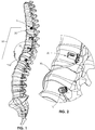
- a spinal correction system in accordance with an embodiment of the present disclosure is generally shown as a spinal correction system 100.
- Spinal correction system 100 may be utilized on, e.g., a scoliotic patient.
- Spinal correction system 100 may safely and reliably correct deformities of vertebral rotation and restore sagittal and coronal balance.
- Spinal correction system 100 includes a fixation member 10, a fulcrum tensioner device 20, and a tensioning member 30.
- fixation member 10 may be, e.g., a cannulated monoaxial screw.
- fixation member 10 includes a head portion 18, a cannulated shank 16 extending distally from head portion 18, and a set screw 12.
- Cannulated shank 16 defines a passage 23 ( FIG. 8 ) configured to receive at least a portion of tensioning member 30 therein.
- Cannulated shank 16 includes threads 16a configured to threadably engage bone.
- Head portion 18 defines a slot 21 configured to receive set screw 12.
- Slot 21 may define a U-shape configured to receive tensioning member 30 therethrough.
- An inner wall 19 of head portion 18 includes threads 18a configured to threadably engage set screw 12.
- Set screw 12 is utilized to secure tensioning member 30 with fixation member 10.
- Set screw 12 includes a base portion 12a and a threaded portion 12b configured to threadably engage threads 18a of head portion 18.
- Base portion 12a is rotatably coupled with threaded portion 12b.
- base portion defines a recess 12f configured to receive a neck portion 12d of threaded portion 12b.
- Base portion further defines a bore 12g dimensioned to receive a pin 12e configured to rotatably secure neck portion 12d of threaded portion 12b.
- base portion 12a may include a planar surface 12c ( FIG. 8 ) configured to engage tensioning member 30.
- base portion 12a is positioned in slot 21 of head portion 18 and in contact with tensioning member 30.
- Base portion 12a maintains its orientation, while threaded portion 12b of set screw 12 is rotated to threadably secure set screw 12 with head portion 18.
- Set screw 12 includes a proximal portion 12c defining a cavity 12h having, e.g., a hex, key feature for non-slip engagement with a driver or other instrument (not shown) to drive set screw 12 into head portion 18. It is contemplated that cavity 12h may have any suitable configuration such as, e.g., slotted, square, star fitting, or a Phillips head, for engagement with the driver.
- cannulated shank 16 includes a distal end 14a defining a distal opening 14c and a proximal end 14b defining a proximal opening 14d.
- a first end of tensioning member 30 may extend through slot 21 of head portion 18 via proximal opening 14d.
- a second end of tensioning member 30 may extend through distal opening 14c.
- a portion of tensioning member 30 extending through proximal opening 14d is secured to proximal end 14b of cannulated shank 16 by set screw 12.
- fulcrum tensioner device 20 includes a housing 24 including a chamber 25 configured to receive a biasing member or spring 21.
- a cap 23 is used to retain spring 21 in chamber 25.
- Cap 23 includes a camming pin 22 configured to slidably engage slots or camming slots 24a defined in housing 24.
- Housing 24 further includes a securing portion 27 defining bores 27a dimensioned to receive bone anchors 26 ( FIG. 13 ).
- tensioning member 30 may be received through spring 21 disposed in chamber 25 of fulcrum tensioner device 20 and may be looped around pin 22. In this manner, the biasing force of spring 21 provides tension in tensioning member 30.
- fulcrum tensioner device 20 may further include a release tab 25 removably received in camming slot 24a of housing 24.
- release tab 25 When release tab 25 is placed in camming slot 24a, spring 21 is compressed and pin 22 is positioned closer to securing portion 27. Under such a configuration, release tab 25 positioned in camming slot 24a inhibits spring 21 from applying tension to tensioning member 30.
- Tensioning member 30 may be, e.g., a flat, flexible tether.
- the flexible nature of tensioning member 30 may enable applications in various surgical procedures.
- tensioning member 30 may be wrapped around a vertebral body "VB".
- Tensioning member 30 may have a thickness that provides a desired amount of flexibility or malleability for a selected application.
- the material of construction e.g., polymeric or metallic, may be selectively chosen to provide the desired amount of flexibility.
- Tensioning member 30 may have a flat rectangular cross-section that enables, e.g., a surface contact, with set screw 12 ( FIG. 8 ).
- tensioning member 30 may be dimensioned to be received in groove 27a ( FIG. 16 ) of securing portion 27 to facilitate or guide placement of tensioning member 30 around securing portion 27.
- tensioning member 30 may include a guide wire, e.g., embedded therein.
- the guide wire may be a stiffening wire to increase the stiffness of tensioning member 30.
- the stiffening wire may be embedded in tensioning member 30 or may be externally bonded (i.e., bonded on an external surface of the body).
- the stiffening wire may be bonded along the entire length of the body or only a portion of the length of the body.
- Tensioning member may be, e.g., a spring or a band.
- Tensioning member 30 may be made from various polymers including, e.g., nylon, Dacron®, Ultra-High-Molecular-Weight Polyethylene (UHMWPE), polypropylene, polyester, polyether ether ketone (PEEK), polyphenylsulfone (PPSU), polyetherimide (PEI), polyacetal, or any combinations thereof. It is also envisioned that tensioning member 30 may be formed from stainless steel, titanium, titanium alloys, cobalt chrome, nitinol, and other suitable biocompatible materials.
- spinal correction system 100 may further include an insertion instrument 40 configured to insert fixation member 10 to the surgical site of interest.
- insertion instrument 40 may be used to insert fixation member 10, e.g., laterally to obtain bi-cortical fixation of fixation member 10.
- Insertion instrument 40 includes a handle 43, a shaft 45 extending from handle 40, and an engaging portion 47 attached to a distal end of shaft 45.
- Engaging portion 47 defines a groove 61 configured to detachably receive a lip 18a ( FIG. 7 ) of head portion 18 of fixation member 10.
- Engaging portion 47 may include, e.g., a snap fit, configuration.
- Engaging portion 47 further defines a notch 44a dimensioned to receive tensioning member 30 therethrough.
- insertion instrument 40 may define a passage 41 extending between proximal and distal ends 42, 44 of insertion instrument 40. Passage 41 may be dimensioned to receive set screw 12 such that set screw 12 may be positioned in slot 21 of head portion 18 of fixation device 10, while head portion 18 is detachably connected to engaging portion 47. In this manner, the use of insertion instrument 40 may facilitate alignment of threaded portion 12b of set screw 12 with threads 18a on inner wall 19 of fixation member 10.
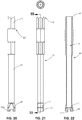
- spinal correction system 100 may include a tensioning instrument 550 configured to apply tension to tensioning member 30 ( FIG. 1 ) coupled with fixation member 10 ( FIG. 1 ).
- Tensioning instrument 550 includes a tensioning mechanism 551 and a clamping mechanism 560.
- Tensioning mechanism 551 includes a tensioning body 552 defining a longitudinal axis "A-A.”
- Tensioning body 552 includes arms 553 extending parallel to the longitudinal axis "A-A.” Arms 553 terminate in fingers 554 that are configured to engage a portion of head portion 18 ( FIG. 3 ) of fixation member 10. Arms 553 may be pivotable towards and away from longitudinal axis "A-A".
- Arms 553 are pivoted away from longitudinal axis "A-A” and out of the parallel arrangement to engage head portion 18 of fixation member 10 and are pivoted towards longitudinal axis "A-A” into the parallel arrangement when engaged with head portion 18.
- Tensioning body 552 further defines a threaded hole 555 along longitudinal axis "A-A.” Threaded hole 555 receives a tensioning screw 556.
- Tensioning screw 556 includes a head 557 adjacent a proximal end thereof and a tensioning disc 558 adjacent a distal end thereof.
- clamping mechanism 560 includes a receiver 562, a clamp base 564, and a clamp arm 566.
- Receiver 562 defines openings 562a sized to permit the arms 553 to pass through the receiver 562.
- a pair of disc pins 563 is received within receiver 562 about tensioning screw 556 such that tensioning screw 556 is retained within threaded hole 555 and fixed relative to receiver 562.
- Clamp base 564 is coupled to receiver 562 by a base screw 565.
- Clamp base 564 may include a protrusion 564a configured to align clamp base 564 with receiver 562.
- Clamp base 564 includes an arm mount 564b configured to pivotally retain clamp arm 566.
- a pivot screw 569 passes through arm mount 564b and clamp arm 566 to retain clamp arm 566 to clamp base 564.
- Clamp arm 566 includes an engagement portion 567 to capture tensioning member 30 between clamp arm 566 and clamp base 564.
- fingers 554 of arms 553 engage head portion 18 of fixation member 10 ( FIG. 3 ) to longitudinally fix tensioning body 552 relative to fixation member 10.
- a portion of tensioning member 30 is passed through passage 23 ( FIG. 8 ) and distal opening 14c of cannulated shank 16 and out of slot 21 ( FIG. 7 ) of head portion 18. Thereafter, the portion of tensioning member 30 is passed between clamp arm 566 and clamp base 564 with clamp arm 566 in a free position, in which tensioning member 30 is freely slidable between clamp base 564 and clamp arm 566.
- Tensioning screw 556 is rotated until receiver 562 is adjacent head portion 18 and head 557 is adjacent tensioning body 552.
- tensioning screw 556 When head 557 of tensioning screw 556 is adjacent tensioning body 552, the portion of tensioning member 30 is held or partially tensioned as clamp arm 566 is moved to the clamped position, in which engagement portion 567 captures tensioning member 30 disposed between clamp arm 566 and clamp base 564 to inhibit tensioning member 30 from moving relative to head portion 18 of fixation member 10.
- tensioning screw 556 With clamp arm 566 in the clamped position, tensioning screw 556 is rotated within tensioning body 552 to move clamping mechanism 560 away from head portion 18 of fixation member 10.
- Tensioning disc 558 of tensioning screw 556 is fixed relative to receiver 562 to move receiver 562 away from fixation member 10.
- the clinician may initially perform various spinal procedures including a thoracotomy, e.g., on the convex side of the spinal deformity.
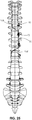
- the clinician may determine the degree of correction needed for the spinal deformity ( FIG. 23 ) of the particular patient and select the optimal placement of spinal correction system 100.
- Fixation members 10 may be placed, e.g., bi-cortically, into two or more vertebral bodies "VB” using insertion instrument 40.
- a first fixation member 10 may be affixed to a cranial vertebral body "VB” and a second fixation member 10 may be affixed to a caudal vertebral body "VB.”
- a number of fulcrum tensioner devices 20 may be selected based on the desired amount of tension applied to tensioning member 30.
- Fulcrum tensioner devices 20 may be affixed to vertebral bodies "VB” at or adjacent, e.g., the apex of the spinal curve or inflection points. Fulcrum tensioner devices 20 are affixed to vertebral bodies "VB” with the use of screws 26.
- Tensioning member 30 may be placed through spring 21 disposed in chamber 25 of fulcrum tensioner device 20 and looped around pin 22 prior to or during the procedure.
- a first end portion of tensioning member 30 may be wrapped around a vertebral body "VB” adjacent cranial vertebral body “VB” having the first fixation member 10 affixed thereto and thereafter inserted into passage 23 ( FIG. 8 ) of cannulated shank 16 of the first fixation member 10.
- tensioning instrument 550 may be used on the first fixation member 10 to apply tension to tensioning member 30.
- Set screw 12 is utilized to secure tensioning member 30 with the first fixation member 10.
- a second end of tensioning member 30 is wrapped around a vertebral body "VB” adjacent caudal vertebral body “VB” having the second fixation member 10 affixed thereto and thereafter inserted into passage 23 of cannulated shank 16 of the second fixation member 10.
- tensioning instrument 550 may be used on the second fixation member 10 to apply tension to tensioning member 30.
- Set screw 12 is utilized to secure tensioning member 30 to the second fixation member 10.
- tensioning member 30 may be removed from camming slot 24a of housing 24 of fulcrum tensioner devices 20 to apply tension to tensioning member 30 for desired correction or re-alignment of the spine. Thereafter, tensioning member 30 may further be manipulated to provide, e.g., proper alignment or tension, with respect to vertebral bodies "VB". To this end, release tab 25 may be re-inserted into camming slots 24a ( FIG. 19 ) of fulcrum tensioner device 20 to inhibit application of tension to tensioning member 30 by spring 21 in order to facilitate re-adjustment of fixation member 10 and/or fulcrum tensioner devices 20.
- a fulcrum tensioner device in accordance with another embodiment of the present disclosure is generally shown as a fulcrum tensioner device 600 configured to be embedded in vertebral body "VB" such that fulcrum tensioner device 600 provides a reduced profile.
- Fulcrum tensioner device 600 includes a housing 624 defining a chamber 625 ( FIG. 32 ) configured to receive a biasing member or spring 621, a divider 655, and a cap 623.
- Divider 655 defines a pair of slits 655a configured to receive tensioning member 30 therethrough such that tensioning member 30 is looped through slots or openings in divider 655.
- Cap 623 is used to retain spring 621 and divider 655 in chamber 625.
- cap 623 may be threadably coupled to an inner wall 624a ( FIG. 32 ) of chamber 625.
- Spring 621 is positioned between a surface of cap 623 and a shoulder defined at an opposed end of chamber 625.
- Housing 624 further includes a flange portion 627 defining bores 627a dimensioned to engage a driver instrument (not shown) to drive fulcrum tensioner device 600 into vertebral body "VB.”
- housing 624 of fulcrum tensioner device 600 includes threads 624b ( FIG. 29B ) configured to engage vertebral body "VB.”
- Flange portion 627 extends radially outward from housing 624 such that flange portion 627 inhibits complete insertion of fulcrum tensioner device 600 in vertebral body "VB.”
- Flange portion 627 has a reduced profile such that when fulcrum tensioner device 600 is received in vertebral body "VB,” flange portion 627 is substantially flush with vertebral body "VB.”
- tensioning member 30 may be received through spring 621 disposed in chamber 625 of fulcrum tensioner device 600 and may be looped through divider 655. In this manner, the biasing force of spring 621 provides tension in tensioning member 30 due to the biasing force of spring 621 being applied to divider 655.
- a pre-drilled bore 601 in vertebral body "VB” may facilitate the insertion process of fulcrum tensioner device 600 into vertebral body "VB.”
- the method of use of fulcrum tensioner device 600 is substantially identical to the method of use described hereinabove with respect to fulcrum tensioner device 20, and thus will not be described herein.
- spinal correction system 100 may be use with other bony elements in a patient. It is within the scope of the present disclosure that a plurality of spinal correction systems 100 may be used to provide a plurality of mounting points along a bony element of a patient's anatomy. It is also contemplated that tensioning member 30 may be coupled to a plurality of fixation member 10 and fulcrum tensioner devices 20 without looping around a bony element.
- spinal correction system 100 may be used with one or more spinal staples.
- the spinal staples may have barbs or other engaging structures on a surface of the spinal staple for positive engagement with the bone while inhibiting relative displacement between the spinal staple and the bone.
- An example of a spinal staple is described in U.S. Patent Application Publication No. 2010/0094358, filed on October 13, 2009 .
- spinal correction system 100 may include a bone screw with barbs or other retention structures located on a distal surface of the bone screw for positive engagement with the bone while inhibiting relative movement between the bone screw and the bone.
Landscapes
- Health & Medical Sciences (AREA)
- Orthopedic Medicine & Surgery (AREA)
- Life Sciences & Earth Sciences (AREA)
- Surgery (AREA)
- Neurology (AREA)
- Heart & Thoracic Surgery (AREA)
- Engineering & Computer Science (AREA)
- Biomedical Technology (AREA)
- Nuclear Medicine, Radiotherapy & Molecular Imaging (AREA)
- Medical Informatics (AREA)
- Molecular Biology (AREA)
- Animal Behavior & Ethology (AREA)
- General Health & Medical Sciences (AREA)
- Public Health (AREA)
- Veterinary Medicine (AREA)
- Surgical Instruments (AREA)
Claims (14)
- Wirbelsäulenkorrektursystem (100), umfassend:ein Spannelement (30); undeine Gelenkpunktspannungsvorrichtung (20), umfassend:ein Gehäuse (24), welches eine Kammer (25) mit einem Vorspannelement (21) darin definiert; undeinen Nockenstift (22), welcher mit dem Vorspannelement funktional gekoppelt ist,wobei das Spannelement konfiguriert ist, um in dem Vorspannelement aufgenommen und rund um den Nockenstift geschlungen zu werden, sodass ein erstes Ende des Spannelements in eine erste Richtung ausgerichtet ist, und ein zweites Ende des Spannelements in einer zweite Richtung ausgerichtet ist, wobei der Nockenstift zwischen einer ausgefahrenen Position, in welcher das Vorspannelement Spannung auf das Spannelement anwendet, und einer eingefahrenen Position, in welcher das Spannelement komprimiert ist, um Anwendung von Spannung auf das Spannelement zu unterbinden, verschiebbar ist.
- Wirbelsäulenkorrektursystem nach Anspruch 1, wobei der Nockenstift zu der ausgefahrenen Position hin vorgespannt ist.
- Wirbelsäulenkorrektursystem nach Anspruch 1, wobei die Gelenkpunktspannungsvorrichtung einen Sicherungsabschnitt (27) beinhaltet, welcher eine Bohrung (27a) definiert, welche konfiguriert ist, um eine Schraube (26) zur Sicherung der Gelenkpunktspannungsvorrichtung an einem Wirbelkörper aufzunehmen.
- Wirbelsäulenkorrektursystem nach Anspruch 3, wobei der Sicherungsabschnitt eine Schraube (26) beinhaltet, welche konfiguriert ist, um die Gelenkpunktspannungsvorrichtung an einem Wirbelkörper zu sichern.
- Wirbelsäulenkorrektursystem nach einem der vorstehenden Ansprüche, wobei das Gehäuse eine Längsachse und einen Schlitz (24a), welcher sich entlang der Längsachse erstreckt, definiert, wobei der Schlitz konfiguriert ist, um den Nockenstift verschiebbar aufzunehmen.
- Wirbelsäulenkorrektursystem nach einem der vorstehenden Ansprüche, wobei die Gelenkpunktspannungsvorrichtung weiter eine Kappe (23) beinhaltet, welche eine Bohrung definiert, welche zur Aufnahme des Nockenstifts dimensioniert ist, wobei die Kappe konfiguriert ist, um das Vorspannelement innerhalb der Kammer des Gehäuses zu halten.
- Wirbelsäulenkorrektursystem nach einem der vorstehenden Ansprüche, weiter ein Fixierelement beinhaltend, welches eine kanülierte Schraube (10) beinhaltet, welche einen für die Aufnahme des Spannelements dimensionierten Korridor (23) definiert;
wobei die kanülierte Schraube ein Gehäuse (18) und eine Welle (16) beinhalten kann, welche sich distal von dem Gehäuse erstreckt, wobei das Gehäuse eine zur Aufnahme des Spannelements dimensionierten Aussparung beinhaltet; und
wobei das Fixierelement weiter eine Einstellungsschraube (12) mit einem Basisabschnitt (12a) und einem Gewindeabschnitt (12b), welcher drehbar mit dem Basisabschnitt gekoppelt ist, beinhalten kann, wobei der Gewindeabschnitt konfiguriert ist, um mittels Gewinde in eine Innenfläche des Gehäuses der kanülierten Schraube einzugreifen, und falls dem so ist,
wobei der Basisabschnitt eine ebene Fläche beinhalten kann, welche adaptiert ist, um in das Spannelement einzugreifen, und
wobei der Basisabschnitt einen nicht kreisförmigen Querschnitt aufweisen kann, um Drehung des Basisabschnitts zu unterbinden, wenn er sich in dem Gehäuse der kanülierten Schraube befindet. - Wirbelsäulenkorrektursystem nach einem der vorstehenden Ansprüche, wobei das Sicherungselement eine Nut (27a) definiert, welche konfiguriert ist, um das Spannelement zu führen.
- Wirbelsäulenkorrektursystem nach einem der vorstehenden Ansprüche, wobei die Gelenkpunktspannungsvorrichtung weiter eine Freigabelasche (25) beinhaltet, welche zur abnehmbaren Aufnahme in dem Nockenschlitz dimensioniert ist, um den Nockenstift in der eingefahrenen Position zu halten.
- Ein Wirbelsäulenkonstrukt (100) zur Korrektur einer Wirbelsäulendeformierung, wobei das Wirbelsäulenkonstrukt umfasst:erste und zweite Fixierelemente (10), wobei das erste Fixierelement an einen ersten Wirbel befestigbar ist und das zweite Fixierelement an einem zweiten Wirbel befestigbar ist;eine Gelenkpunktspannungsvorrichtung (20), welche an einem dritten Wirbel befestigbar ist, wobei die Gelenkpunktspannungsvorrichtung beinhaltet:ein Gehäuse (24);ein Vorspannelement (21), welches sich in dem Gehäuse befindet, undeinen Nockenstift (22), welcher mit dem Vorspannelement funktional gekoppelt und zwischen einer ausgefahrenen Position und einer eingefahrenen Position verschiebbar ist; undein Spannelement (30), welches mit dem ersten Fixierelement, dem zweiten Fixierelement und der Gelenkpunktspannungsvorrichtung funktional gekoppelt ist, wobei ein erstes Ende des Spannelements an dem ersten Fixierelement gesichert werden kann, ein zweites Ende des Spannelements an dem zweiten Fixierelement gesichert werden kann, und ein Zwischenabschnitt des Spannelements rund um den Nockenstift geschlungen ist.
- Wirbelsäulenkonstrukt nach Anspruch 10, wobei die Gelenkpunktspannungsvorrichtung weiter einen Sicherungsabschnitt (27) mit einer Bohrung beinhaltet und unter Verwendung einer durch die Bohrung eingeführten Schraube an dem dritten Wirbel befestigbar ist.
- Wirbelsäulenkonstrukt nach Anspruch 10, wobei die Gelenkpunktspannungsvorrichtung weiter einen Nockenschlitz (24a) und eine Freigabelasche (25) beinhaltet, wobei die Freigabelasche in dem Nockenschlitz aufgenommen wird, um den Nockenstift in der eingefahrenen Position zu halten.
- Wirbelsäulenkonstrukt nach einem der vorstehenden Ansprüche und weiter ein Spanninstrument (550) umfassend, welches konfiguriert ist, um Spannung auf das Spannelement anzuwenden, wobei das Spanninstrument eine Spannschraube (556) und einen Klemmmechanismus (560) beinhaltet, wobei der Klemmmechanismus einen Klemmarm (566) mit einer freien Position, in welcher das Spannelement frei durch den Klemmmechanismus gleiten kann, und einer gesperrten Position, in welcher das Spannelement relativ zu dem Klemmmechanismus fixiert ist, beinhaltet, wobei die Spannschraube konfiguriert ist, um den Klemmmechanismus von einem von dem ersten und zweiten Fixierelement weg zu bewegen, um Spannung auf das Spannelement anzuwenden, wenn der Klemmmechanismus sich in der gesperrten Position befindet.
- Wirbelsäulenkorrektursystem nach Anspruch 1, wobei das Gehäuse einen Korpus und einen Flansch, welcher sich von dem Korpus radial nach außen erstreckt, beinhaltet, wobei der Korpus konfiguriert ist, um in einem Wirbelkörper aufgenommen zu werden; und weiter wobei optional der Nockenstift zu der ausgefahrenen Position hin vorgespannt ist.
Applications Claiming Priority (2)
| Application Number | Priority Date | Filing Date | Title |
|---|---|---|---|
| US201662280202P | 2016-01-19 | 2016-01-19 | |
| PCT/US2017/014114 WO2017127532A1 (en) | 2016-01-19 | 2017-01-19 | Spinal correction system and method of use thereof |
Publications (3)
| Publication Number | Publication Date |
|---|---|
| EP3405129A1 EP3405129A1 (de) | 2018-11-28 |
| EP3405129A4 EP3405129A4 (de) | 2019-09-18 |
| EP3405129B1 true EP3405129B1 (de) | 2021-06-23 |
Family
ID=59362106
Family Applications (1)
| Application Number | Title | Priority Date | Filing Date |
|---|---|---|---|
| EP17741917.3A Active EP3405129B1 (de) | 2016-01-19 | 2017-01-19 | Wirbelsäulenkorrektursystem |
Country Status (3)
| Country | Link |
|---|---|
| US (1) | US10869693B2 (de) |
| EP (1) | EP3405129B1 (de) |
| WO (1) | WO2017127532A1 (de) |
Families Citing this family (12)
| Publication number | Priority date | Publication date | Assignee | Title |
|---|---|---|---|---|
| WO2017201437A1 (en) | 2016-05-19 | 2017-11-23 | Auctus Surgical, Llc | Spinal curvature modulation systems |
| US12262917B2 (en) | 2016-05-19 | 2025-04-01 | Auctus Surgical, Inc. | Spinal curvature modulation systems and methods |
| WO2019118844A1 (en) * | 2017-12-14 | 2019-06-20 | K2M, Inc. | Band tensioning system |
| US11020149B2 (en) * | 2018-02-28 | 2021-06-01 | Globus Medical Inc. | Scoliosis correction systems, methods, and instruments |
| US11648000B2 (en) | 2018-07-30 | 2023-05-16 | Braunvest Llc | Vertebral probes and related surgical methods |
| US12232781B2 (en) | 2018-07-30 | 2025-02-25 | BraunVest, LLC | Cortical/cancellous bone probes and related surgical methods |
| US11246636B2 (en) | 2019-04-26 | 2022-02-15 | Braunvest Llc | Systems, methods, and apparatus for spinal deformity correction |
| US12329429B2 (en) | 2019-04-26 | 2025-06-17 | Braunvest Llc | Systems, methods, and apparatus for spinal deformity correction |
| US12419670B2 (en) | 2019-04-26 | 2025-09-23 | BraunVest, LLC | Methods for bone compression and/or fixation |
| US12193711B2 (en) * | 2020-12-17 | 2025-01-14 | Md Antonacci Family Trust | Method for improved spinal correction surgery implementing non-fusion anterior scoliosis correction techniques |
| US20240108381A1 (en) * | 2022-10-04 | 2024-04-04 | The Board Of Regents Of The University Of Texas System | Systems and methods for applying tension to the spine |
| US12343055B1 (en) | 2024-08-02 | 2025-07-01 | Institute For Spine & Scoliosis, P.A. | Anchor device for bone implantation during surgical procedures |
Family Cites Families (17)
| Publication number | Priority date | Publication date | Assignee | Title |
|---|---|---|---|---|
| US6296643B1 (en) * | 1999-04-23 | 2001-10-02 | Sdgi Holdings, Inc. | Device for the correction of spinal deformities through vertebral body tethering without fusion |
| US6783527B2 (en) * | 2001-10-30 | 2004-08-31 | Sdgi Holdings, Inc. | Flexible spinal stabilization system and method |
| US7887482B2 (en) | 2002-10-25 | 2011-02-15 | K2M, Inc. | Minimal access lumbar diskectomy instrumentation and method |
| US7806914B2 (en) * | 2003-12-31 | 2010-10-05 | Spine Wave, Inc. | Dynamic spinal stabilization system |
| US20080140202A1 (en) | 2006-12-08 | 2008-06-12 | Randall Noel Allard | Energy-Storing Spinal Implants and Methods of Use |
| US8470002B2 (en) * | 2007-02-20 | 2013-06-25 | Warsaw Orthopedic, Inc. | Resorbable release mechanism for a surgical tether and methods of use |
| US7942910B2 (en) * | 2007-05-16 | 2011-05-17 | Ortho Innovations, Llc | Polyaxial bone screw |
| US20100036424A1 (en) * | 2007-06-22 | 2010-02-11 | Simpirica Spine, Inc. | Methods and systems for increasing the bending stiffness and constraining the spreading of a spinal segment |
| US20100094358A1 (en) | 2008-10-10 | 2010-04-15 | K2M, Inc. | Spinal staple |
| US20100292736A1 (en) * | 2009-05-15 | 2010-11-18 | Warsaw Orthopedic, Inc. | Linkage for Connection of Fusion and Non-Fusion Systems |
| EP2316363A1 (de) * | 2009-10-27 | 2011-05-04 | Zimmer Spine | Knochenhaltevorrichtung |
| WO2012154265A1 (en) * | 2011-02-22 | 2012-11-15 | Simpirica Spine, Inc. | Spinous process cerclage for bone graft containment |
| GB201220042D0 (en) * | 2012-11-07 | 2012-12-19 | Murray David W | Adjusting spinal curvature |
| EP2777569B1 (de) | 2013-03-11 | 2019-12-25 | K2M, Inc. | Flexibles Befestigungssystem |
| US20150039029A1 (en) * | 2013-08-01 | 2015-02-05 | Dallen Medical, Inc. | Implant device and system for stabilized fixation of bone and soft tissue |
| US9433442B2 (en) * | 2014-01-23 | 2016-09-06 | Warsaw Orthopedic, Inc. | Spinal correction system and method |
| US9757167B2 (en) * | 2015-03-11 | 2017-09-12 | K2M, Inc. | Inserter and method for securing an implant to a spinal process with a flexible fastening system |
-
2017
- 2017-01-19 EP EP17741917.3A patent/EP3405129B1/de active Active
- 2017-01-19 US US16/071,212 patent/US10869693B2/en active Active
- 2017-01-19 WO PCT/US2017/014114 patent/WO2017127532A1/en not_active Ceased
Also Published As
| Publication number | Publication date |
|---|---|
| WO2017127532A1 (en) | 2017-07-27 |
| US20200085471A1 (en) | 2020-03-19 |
| US10869693B2 (en) | 2020-12-22 |
| EP3405129A1 (de) | 2018-11-28 |
| EP3405129A4 (de) | 2019-09-18 |
Similar Documents
| Publication | Publication Date | Title |
|---|---|---|
| US10869693B2 (en) | Spinal correction system and method of use thereof | |
| US12171465B2 (en) | Device and method for treatment of spinal deformity | |
| EP2645949B1 (de) | Stangenhaltevorrichtung | |
| US10470803B2 (en) | Flexible fastening system | |
| US9204908B2 (en) | Segmental orthopedic device for spinal elongation and for treatment of scoliosis | |
| US7776070B2 (en) | Occipital plating systems and methods | |
| US8523922B2 (en) | Dynamic multi-axial fastener | |
| EP2422728B1 (de) | Anker zur Befestigung an eine Knochenstruktur | |
| US20090093843A1 (en) | Dynamic spine stabilization system | |
| US20050277920A1 (en) | Non-fusion spinal correction systems and methods | |
| US8591551B2 (en) | Linked spinal stabilization elements for spinal fixation | |
| WO2018022769A1 (en) | Orthopedic tethered implants and system | |
| US20100292736A1 (en) | Linkage for Connection of Fusion and Non-Fusion Systems | |
| WO2014062942A1 (en) | Spinal correction adjustment systems and methods | |
| EP3606451B1 (de) | Querstecker |
Legal Events
| Date | Code | Title | Description |
|---|---|---|---|
| STAA | Information on the status of an ep patent application or granted ep patent |
Free format text: STATUS: THE INTERNATIONAL PUBLICATION HAS BEEN MADE |
|
| PUAI | Public reference made under article 153(3) epc to a published international application that has entered the european phase |
Free format text: ORIGINAL CODE: 0009012 |
|
| STAA | Information on the status of an ep patent application or granted ep patent |
Free format text: STATUS: REQUEST FOR EXAMINATION WAS MADE |
|
| 17P | Request for examination filed |
Effective date: 20180709 |
|
| AK | Designated contracting states |
Kind code of ref document: A1 Designated state(s): AL AT BE BG CH CY CZ DE DK EE ES FI FR GB GR HR HU IE IS IT LI LT LU LV MC MK MT NL NO PL PT RO RS SE SI SK SM TR |
|
| AX | Request for extension of the european patent |
Extension state: BA ME |
|
| DAV | Request for validation of the european patent (deleted) | ||
| DAX | Request for extension of the european patent (deleted) | ||
| A4 | Supplementary search report drawn up and despatched |
Effective date: 20190821 |
|
| RIC1 | Information provided on ipc code assigned before grant |
Ipc: A61B 17/68 20060101ALI20190815BHEP Ipc: A61B 17/86 20060101ALI20190815BHEP Ipc: A61B 17/04 20060101ALI20190815BHEP Ipc: A61B 17/70 20060101AFI20190815BHEP Ipc: A61B 17/88 20060101ALI20190815BHEP Ipc: A61B 17/08 20060101ALI20190815BHEP Ipc: A61B 17/84 20060101ALI20190815BHEP |
|
| GRAP | Despatch of communication of intention to grant a patent |
Free format text: ORIGINAL CODE: EPIDOSNIGR1 |
|
| STAA | Information on the status of an ep patent application or granted ep patent |
Free format text: STATUS: GRANT OF PATENT IS INTENDED |
|
| INTG | Intention to grant announced |
Effective date: 20210121 |
|
| GRAS | Grant fee paid |
Free format text: ORIGINAL CODE: EPIDOSNIGR3 |
|
| GRAA | (expected) grant |
Free format text: ORIGINAL CODE: 0009210 |
|
| STAA | Information on the status of an ep patent application or granted ep patent |
Free format text: STATUS: THE PATENT HAS BEEN GRANTED |
|
| AK | Designated contracting states |
Kind code of ref document: B1 Designated state(s): AL AT BE BG CH CY CZ DE DK EE ES FI FR GB GR HR HU IE IS IT LI LT LU LV MC MK MT NL NO PL PT RO RS SE SI SK SM TR |
|
| REG | Reference to a national code |
Ref country code: GB Ref legal event code: FG4D |
|
| REG | Reference to a national code |
Ref country code: CH Ref legal event code: EP |
|
| REG | Reference to a national code |
Ref country code: AT Ref legal event code: REF Ref document number: 1403605 Country of ref document: AT Kind code of ref document: T Effective date: 20210715 Ref country code: DE Ref legal event code: R096 Ref document number: 602017040798 Country of ref document: DE |
|
| REG | Reference to a national code |
Ref country code: IE Ref legal event code: FG4D |
|
| REG | Reference to a national code |
Ref country code: NL Ref legal event code: FP |
|
| REG | Reference to a national code |
Ref country code: LT Ref legal event code: MG9D |
|
| PG25 | Lapsed in a contracting state [announced via postgrant information from national office to epo] |
Ref country code: HR Free format text: LAPSE BECAUSE OF FAILURE TO SUBMIT A TRANSLATION OF THE DESCRIPTION OR TO PAY THE FEE WITHIN THE PRESCRIBED TIME-LIMIT Effective date: 20210623 Ref country code: BG Free format text: LAPSE BECAUSE OF FAILURE TO SUBMIT A TRANSLATION OF THE DESCRIPTION OR TO PAY THE FEE WITHIN THE PRESCRIBED TIME-LIMIT Effective date: 20210923 Ref country code: LT Free format text: LAPSE BECAUSE OF FAILURE TO SUBMIT A TRANSLATION OF THE DESCRIPTION OR TO PAY THE FEE WITHIN THE PRESCRIBED TIME-LIMIT Effective date: 20210623 Ref country code: FI Free format text: LAPSE BECAUSE OF FAILURE TO SUBMIT A TRANSLATION OF THE DESCRIPTION OR TO PAY THE FEE WITHIN THE PRESCRIBED TIME-LIMIT Effective date: 20210623 |
|
| REG | Reference to a national code |
Ref country code: AT Ref legal event code: MK05 Ref document number: 1403605 Country of ref document: AT Kind code of ref document: T Effective date: 20210623 |
|
| PG25 | Lapsed in a contracting state [announced via postgrant information from national office to epo] |
Ref country code: LV Free format text: LAPSE BECAUSE OF FAILURE TO SUBMIT A TRANSLATION OF THE DESCRIPTION OR TO PAY THE FEE WITHIN THE PRESCRIBED TIME-LIMIT Effective date: 20210623 Ref country code: GR Free format text: LAPSE BECAUSE OF FAILURE TO SUBMIT A TRANSLATION OF THE DESCRIPTION OR TO PAY THE FEE WITHIN THE PRESCRIBED TIME-LIMIT Effective date: 20210924 Ref country code: RS Free format text: LAPSE BECAUSE OF FAILURE TO SUBMIT A TRANSLATION OF THE DESCRIPTION OR TO PAY THE FEE WITHIN THE PRESCRIBED TIME-LIMIT Effective date: 20210623 Ref country code: SE Free format text: LAPSE BECAUSE OF FAILURE TO SUBMIT A TRANSLATION OF THE DESCRIPTION OR TO PAY THE FEE WITHIN THE PRESCRIBED TIME-LIMIT Effective date: 20210623 Ref country code: NO Free format text: LAPSE BECAUSE OF FAILURE TO SUBMIT A TRANSLATION OF THE DESCRIPTION OR TO PAY THE FEE WITHIN THE PRESCRIBED TIME-LIMIT Effective date: 20210923 |
|
| PG25 | Lapsed in a contracting state [announced via postgrant information from national office to epo] |
Ref country code: AT Free format text: LAPSE BECAUSE OF FAILURE TO SUBMIT A TRANSLATION OF THE DESCRIPTION OR TO PAY THE FEE WITHIN THE PRESCRIBED TIME-LIMIT Effective date: 20210623 Ref country code: CZ Free format text: LAPSE BECAUSE OF FAILURE TO SUBMIT A TRANSLATION OF THE DESCRIPTION OR TO PAY THE FEE WITHIN THE PRESCRIBED TIME-LIMIT Effective date: 20210623 Ref country code: EE Free format text: LAPSE BECAUSE OF FAILURE TO SUBMIT A TRANSLATION OF THE DESCRIPTION OR TO PAY THE FEE WITHIN THE PRESCRIBED TIME-LIMIT Effective date: 20210623 Ref country code: ES Free format text: LAPSE BECAUSE OF FAILURE TO SUBMIT A TRANSLATION OF THE DESCRIPTION OR TO PAY THE FEE WITHIN THE PRESCRIBED TIME-LIMIT Effective date: 20210623 Ref country code: RO Free format text: LAPSE BECAUSE OF FAILURE TO SUBMIT A TRANSLATION OF THE DESCRIPTION OR TO PAY THE FEE WITHIN THE PRESCRIBED TIME-LIMIT Effective date: 20210623 Ref country code: PT Free format text: LAPSE BECAUSE OF FAILURE TO SUBMIT A TRANSLATION OF THE DESCRIPTION OR TO PAY THE FEE WITHIN THE PRESCRIBED TIME-LIMIT Effective date: 20211025 Ref country code: SM Free format text: LAPSE BECAUSE OF FAILURE TO SUBMIT A TRANSLATION OF THE DESCRIPTION OR TO PAY THE FEE WITHIN THE PRESCRIBED TIME-LIMIT Effective date: 20210623 Ref country code: SK Free format text: LAPSE BECAUSE OF FAILURE TO SUBMIT A TRANSLATION OF THE DESCRIPTION OR TO PAY THE FEE WITHIN THE PRESCRIBED TIME-LIMIT Effective date: 20210623 |
|
| PG25 | Lapsed in a contracting state [announced via postgrant information from national office to epo] |
Ref country code: PL Free format text: LAPSE BECAUSE OF FAILURE TO SUBMIT A TRANSLATION OF THE DESCRIPTION OR TO PAY THE FEE WITHIN THE PRESCRIBED TIME-LIMIT Effective date: 20210623 |
|
| REG | Reference to a national code |
Ref country code: DE Ref legal event code: R097 Ref document number: 602017040798 Country of ref document: DE |
|
| PG25 | Lapsed in a contracting state [announced via postgrant information from national office to epo] |
Ref country code: DK Free format text: LAPSE BECAUSE OF FAILURE TO SUBMIT A TRANSLATION OF THE DESCRIPTION OR TO PAY THE FEE WITHIN THE PRESCRIBED TIME-LIMIT Effective date: 20210623 |
|
| PLBE | No opposition filed within time limit |
Free format text: ORIGINAL CODE: 0009261 |
|
| STAA | Information on the status of an ep patent application or granted ep patent |
Free format text: STATUS: NO OPPOSITION FILED WITHIN TIME LIMIT |
|
| 26N | No opposition filed |
Effective date: 20220324 |
|
| PG25 | Lapsed in a contracting state [announced via postgrant information from national office to epo] |
Ref country code: AL Free format text: LAPSE BECAUSE OF FAILURE TO SUBMIT A TRANSLATION OF THE DESCRIPTION OR TO PAY THE FEE WITHIN THE PRESCRIBED TIME-LIMIT Effective date: 20210623 |
|
| PG25 | Lapsed in a contracting state [announced via postgrant information from national office to epo] |
Ref country code: IT Free format text: LAPSE BECAUSE OF FAILURE TO SUBMIT A TRANSLATION OF THE DESCRIPTION OR TO PAY THE FEE WITHIN THE PRESCRIBED TIME-LIMIT Effective date: 20210623 |
|
| PG25 | Lapsed in a contracting state [announced via postgrant information from national office to epo] |
Ref country code: MC Free format text: LAPSE BECAUSE OF FAILURE TO SUBMIT A TRANSLATION OF THE DESCRIPTION OR TO PAY THE FEE WITHIN THE PRESCRIBED TIME-LIMIT Effective date: 20210623 |
|
| REG | Reference to a national code |
Ref country code: CH Ref legal event code: PL |
|
| REG | Reference to a national code |
Ref country code: BE Ref legal event code: MM Effective date: 20220131 |
|
| PG25 | Lapsed in a contracting state [announced via postgrant information from national office to epo] |
Ref country code: LU Free format text: LAPSE BECAUSE OF NON-PAYMENT OF DUE FEES Effective date: 20220119 |
|
| PG25 | Lapsed in a contracting state [announced via postgrant information from national office to epo] |
Ref country code: BE Free format text: LAPSE BECAUSE OF NON-PAYMENT OF DUE FEES Effective date: 20220131 |
|
| PG25 | Lapsed in a contracting state [announced via postgrant information from national office to epo] |
Ref country code: LI Free format text: LAPSE BECAUSE OF NON-PAYMENT OF DUE FEES Effective date: 20220131 Ref country code: CH Free format text: LAPSE BECAUSE OF NON-PAYMENT OF DUE FEES Effective date: 20220131 |
|
| PG25 | Lapsed in a contracting state [announced via postgrant information from national office to epo] |
Ref country code: IE Free format text: LAPSE BECAUSE OF NON-PAYMENT OF DUE FEES Effective date: 20220119 |
|
| P01 | Opt-out of the competence of the unified patent court (upc) registered |
Effective date: 20230522 |
|
| PG25 | Lapsed in a contracting state [announced via postgrant information from national office to epo] |
Ref country code: HU Free format text: LAPSE BECAUSE OF FAILURE TO SUBMIT A TRANSLATION OF THE DESCRIPTION OR TO PAY THE FEE WITHIN THE PRESCRIBED TIME-LIMIT; INVALID AB INITIO Effective date: 20170119 |
|
| PG25 | Lapsed in a contracting state [announced via postgrant information from national office to epo] |
Ref country code: MK Free format text: LAPSE BECAUSE OF FAILURE TO SUBMIT A TRANSLATION OF THE DESCRIPTION OR TO PAY THE FEE WITHIN THE PRESCRIBED TIME-LIMIT Effective date: 20210623 Ref country code: CY Free format text: LAPSE BECAUSE OF FAILURE TO SUBMIT A TRANSLATION OF THE DESCRIPTION OR TO PAY THE FEE WITHIN THE PRESCRIBED TIME-LIMIT Effective date: 20210623 |
|
| PG25 | Lapsed in a contracting state [announced via postgrant information from national office to epo] |
Ref country code: TR Free format text: LAPSE BECAUSE OF FAILURE TO SUBMIT A TRANSLATION OF THE DESCRIPTION OR TO PAY THE FEE WITHIN THE PRESCRIBED TIME-LIMIT Effective date: 20210623 |
|
| PG25 | Lapsed in a contracting state [announced via postgrant information from national office to epo] |
Ref country code: MT Free format text: LAPSE BECAUSE OF FAILURE TO SUBMIT A TRANSLATION OF THE DESCRIPTION OR TO PAY THE FEE WITHIN THE PRESCRIBED TIME-LIMIT Effective date: 20210623 |
|
| REG | Reference to a national code |
Ref country code: NL Ref legal event code: PD Owner name: VB SPINE US OPCO LLC; US Free format text: DETAILS ASSIGNMENT: CHANGE OF OWNER(S), ASSIGNMENT; FORMER OWNER NAME: STRYKER CORPORATION Effective date: 20250612 |
|
| REG | Reference to a national code |
Ref country code: DE Ref legal event code: R081 Ref document number: 602017040798 Country of ref document: DE Owner name: VB SPINE US OPCO LLC, WILMINGTON, US Free format text: FORMER OWNER: STRYKER CORPORATION, PORTAGE, MI, US Ref country code: DE Ref legal event code: R081 Ref document number: 602017040798 Country of ref document: DE Owner name: VB SPINE US OPCO LLC, WILMINGTON, US Free format text: FORMER OWNER: K2M, INC., LEESBURG, VA, US |
|
| REG | Reference to a national code |
Ref country code: GB Ref legal event code: 732E Free format text: REGISTERED BETWEEN 20250626 AND 20250702 |
|
| PGFP | Annual fee paid to national office [announced via postgrant information from national office to epo] |
Ref country code: GB Payment date: 20251127 Year of fee payment: 10 |
|
| PGFP | Annual fee paid to national office [announced via postgrant information from national office to epo] |
Ref country code: NL Payment date: 20251215 Year of fee payment: 10 Ref country code: FR Payment date: 20251124 Year of fee payment: 10 |
|
| PGFP | Annual fee paid to national office [announced via postgrant information from national office to epo] |
Ref country code: DE Payment date: 20251126 Year of fee payment: 10 |