EP3405287B1 - Verschleissschutzelement für eine zerkleinerungseinrichtung - Google Patents
Verschleissschutzelement für eine zerkleinerungseinrichtung Download PDFInfo
- Publication number
- EP3405287B1 EP3405287B1 EP17700339.9A EP17700339A EP3405287B1 EP 3405287 B1 EP3405287 B1 EP 3405287B1 EP 17700339 A EP17700339 A EP 17700339A EP 3405287 B1 EP3405287 B1 EP 3405287B1
- Authority
- EP
- European Patent Office
- Prior art keywords
- wear
- area
- region
- fastening
- resistant element
- Prior art date
- Legal status (The legal status is an assumption and is not a legal conclusion. Google has not performed a legal analysis and makes no representation as to the accuracy of the status listed.)
- Active
Links
Images


Classifications
-
- B—PERFORMING OPERATIONS; TRANSPORTING
- B02—CRUSHING, PULVERISING, OR DISINTEGRATING; PREPARATORY TREATMENT OF GRAIN FOR MILLING
- B02C—CRUSHING, PULVERISING, OR DISINTEGRATING IN GENERAL; MILLING GRAIN
- B02C4/00—Crushing or disintegrating by roller mills
- B02C4/28—Details
- B02C4/30—Shape or construction of rollers
- B02C4/305—Wear resistant rollers
-
- B—PERFORMING OPERATIONS; TRANSPORTING
- B02—CRUSHING, PULVERISING, OR DISINTEGRATING; PREPARATORY TREATMENT OF GRAIN FOR MILLING
- B02C—CRUSHING, PULVERISING, OR DISINTEGRATING IN GENERAL; MILLING GRAIN
- B02C2210/00—Codes relating to different types of disintegrating devices
- B02C2210/02—Features for generally used wear parts on beaters, knives, rollers, anvils, linings and the like
Definitions
- the invention relates to a wear protection element for partial insertion into a recess on the surface of a wear surface of a comminution device and a comminution device with such a wear protection element.
- comminution devices such as grinding rollers
- the surface of a wear surface is subject to high wear when the comminution device is in operation.
- this wear it is, for example, from the DE 2006 010 042 A1 known to apply additional wear protection elements to the surface of the grinding roller.
- roll mills or roll crushers for comminuting materials for cement production are known, which have a wear protection element which is mounted in a recess in the surface of the roller mill or the roller crusher.
- the WO 2016/150719 A1 also discloses wear protection elements for a mill or a crusher, which are exemplarily sleeve-shaped.
- a wear protection element for a mill or a crusher is known, a fastening area of the wear protection element extending in the form of a sleeve around a wear area of the wear protection element.
- a drill bit of a rock drill is known.
- the drill bit has wear protection elements which are inserted into a recess in the surface of the wear surface.
- the US 2008/142272 A1 also relates to wear protection for comminution devices, such as, for example, crushers, grinding rollers and drills, the wear protection element being arranged in a recess in a wear surface.
- the invention comprises a wear protection element for partial insertion into a recess on the surface of a wear surface of a comminution device, the wear protection element having a fastening area that can be connected to the recess in the surface of the wear surface and a wear area that is at least partially from the Surface of the wear surface protrudes.
- the fastening area comprises a material that has a lower wear resistance than the material of the wear area, the wear area extending at the level of the wear protection element beyond the fastening area.
- the fastening area also has a lower cylindrical area on which the wear area rests and an upper sleeve-shaped area which at least partially surrounds the wear area.
- the fastening area has a receiving area for receiving the wear area, which is designed such that it centers the wear area relative to the fastening area, the receiving area having at least one recess and the wear area having a projection that interacts with the recess or the receiving area having a projection and the wear area has a recess that cooperates with the projection.
- the crushing device is, for example, a roller mill, a roller crusher, a hammer mill or a vertical roller mill, the wear surface in particular the surface of a grinding roller exposed to high wear during operation of the crushing device, the hammer tools and the surface of the grinding track of a hammer mill or the surface of the Rolls and the grinding table of a vertical roller mill is.
- the wear protection element is, for example, cylindrical or has a square cross section.
- one end of the wear protection elements is designed in such a way that it can be fastened to the surface of the wear surface, in particular in a recess in the surface of the wear surface.
- the wear protection element is designed in the form of a plate. This is particularly advantageous when such a wear protection element is used on, for example, a grinding track of a hammer mill or a vertical roller mill.
- the fastening area is preferably arranged in such a way that it is exposed to no or only very little wear during operation of the shredding device. In particular, the fastening area is used to fasten the wear protection element to the surface of the wear surface.
- the wear area is arranged on the fastening area and extends at the level of the wear protection element beyond the fastening area, so that the wear area is exposed to the majority of the wear acting on the wear protection element.
- Such a wear protection element can be produced much more economically, since it is possible to dispense with the formation of the entire wear protection element from the more expensive, more wear-resistant material.
- the area of the wear protection element that is exposed to no or only very little wear has a less wear-resistant material, which results in lower material costs.
- a sleeve-shaped fastening area offers the advantage of being particularly easy to manufacture.
- Sleeve-shaped is to be understood in particular as the fact that the fastening area is cylindrical with a central, coaxial recess facing the wear area.
- the fastening area has a lower cylindrical area on which the wear area rests and an upper, for example, thin-walled, sleeve-shaped area which at least partially surrounds the wear area.
- the sleeve-shaped area in particular has at least the same or a greater longitudinal extent than the cylindrical area.
- the wear area preferably has a cylindrical area which is designed in such a way that it interacts with the sleeve-shaped area of the fastening area in a precisely fitting manner. In particular, the wear area is designed entirely as a cylinder.
- the material of the wear area comprises a ceramic material, such as, for example, tungsten carbide WC, titanium carbide TiC, titanium carbonitride TiCN, vanadium carbide VC, chromium carbide CrC, tantalum carbide TaC, boron carbide BC, niobium carbide NbC, molybdenum carbide, molybdenum carbide Mo2C, aluminum oxide Al2O3, aluminum oxide Al2O3, aluminum oxide Al2O3 SiC.
- particles of industrial diamonds, in particular high-strength ceramics are preferably embedded in a ceramic or metallic matrix in the wear area.
- the material of the fastening area comprises a steel, such as, for example, tempered structural steel.
- the attachment area has a receiving area for receiving the wear area, which is designed such that it centers the wear area relative to the attachment area.
- the receiving area is preferably formed on the side surface of the fastening area facing the wear area.
- the surface of the wear area facing the fastening area is designed in such a way that it interacts with the receiving area.
- the receiving area has, for example, at least one recess and the wear area has a projection which interacts with the recess.
- the receiving area has a projection and the wear area has a corresponding recess.
- the wear protection element has a frontal recess, in particular a bore, which points in the direction of the wear surface of the comminution device.
- the fastening area preferably has the frontal recess.
- the recess is designed in particular coaxially to the wear protection element. Such a recess results in a material saving of the fastening area and thus a cost reduction of the wear protection element.
- the wear area is arranged at least partially within the sleeve-shaped area of the fastening area.
- the sleeve-shaped fastening area arranged at least partially around the wear area offers the advantage of a simple arrangement of the wear area on the fastening area and simple reworking of the casing of the wear protection element.
- the fastening area and the wear area are materially connected to one another, in particular glued or soldered.
- a screw connection of the wear area and the fastening area is also conceivable.
- a material connection offers a simple possibility of fastening the wear area to the fastening area, the wear area preferably being detachably attached to the fastening area, so that if the wear area is worn, it can be exchanged in a simple manner. An exchange of the fastening area is therefore not necessary in the event of wear of the wear area.
- the fastening area comprises less than 45%, preferably less than 30%, most preferably less than 20% of the wear protection element.
- the invention further comprises a comminution device having a wear surface and a wear protection element as described above, the wear protection element being at least partially attached in a recess in the surface wear surface, in particular a grinding roller.
- the fastening area of the wear protection element is materially connected to the grinding roller, in particular welded, glued or soldered.
- the fastening area is preferably soldered, glued or welded to the recess in the wear surface.
- the comminution device is, for example, a grinding roller for comminuting the bed of material or a vertical roller mill.
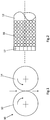
- a comminution device 10 in particular a roller mill, is shown schematically.
- the comminution device 10 comprises two grinding rollers, shown schematically as circles, with wear surfaces 12, 14, which have the same diameter and are arranged next to one another.
- a grinding gap is formed between the wear surfaces 12, 14 of the grinding rollers, the size of which is adjustable, for example.
- the grinding rollers rotate in the opposite direction to one another in the direction of rotation shown by the arrows, with ground material running through the grinding gap in the direction of fall and being ground.
- Fig. 2 shows an end region of a grinding roller which has a wear surface 12 to which wear protection elements 16 are attached.
- the wear protection elements 16 are mounted in the outer periphery of the surface of the grinding roller.
- the wear protection elements 16, which are spaced apart from one another and arranged next to one another have Fig. 2 a circular cross-section. It is also conceivable that the wear protection elements 16 vary over the surface of the grinding roller in terms of size, number, cross-sectional shape and arrangement in relation to one another, for example to compensate for local differences in wear during operation of the comminution device 10.
- the grinding roller has wear protection corner elements 17 attached to its end, which for example have a rectangular cross section and are arranged in a row next to one another in such a way that they form a ring over the circumference of the grinding roller.
- wear protection corner elements 17 There are also other cross-sectional shapes of the wear protection corner elements 17 conceivable, which are from the in Fig. 2 shown cross-sectional shape. An arrangement of the wear protection corner elements 17 at a distance from one another is also possible.
- Fig. 2 only the left end of the grinding roller with the wear surface 12 is shown by way of example, the right end not shown advantageously being identical in structure.
- FIG. 4 shows a wear protection element 16a not included in the invention, which is located in a recess 26 in with the wear surface 12 of the grinding roller according to FIG Figs. 1 and 2 is arranged.
- the wear protection element 16a has an attachment area 24 and a wear area 22, the attachment area being arranged in the recess 26 on the surface of the wear surface 12 of the grinding roller and being connected to the wear surface 12 of the grinding roller.
- the wear protection element 16a is materially bonded to the fastening area 24 with the recess in the surface of the wear surface 12 of the grinding roller, in particular welded, soldered or glued or positively connected, in particular screwed or wedged.
- the wear area 22 of the wear protection element 16a is arranged at least partially outside the recess 26 in the wear surface 12, so that it protrudes from the surface of the wear surface 12 in the radial direction of the grinding roller (not shown).
- the fastening area 24 comprises approximately one third of the entire wear protection element 16a, the wear area 22 approximately comprising the other two thirds.
- the fastening region 24 has a receiving region 18 which comprises the surface of the fastening region facing the wear region 22.
- the receiving area 18 is arranged between the wear area 22 and the fastening area 24 and is in particular arched so that the fastening area 24 of the wear protection element 16a has an inwardly pointing arch at the end facing the wear area 22. This curvature is used to position the wear area 22 on the fastening area 24.
- the wear area 22 of the wear protection element 16a has a material with a higher wear resistance than the material of the fastening area 24.
- the wear area 22 has a ceramic material, such as tungsten carbide, titanium carbide, titanium carbonitride, vanadium carbide, chromium carbide, tantalum carbide, boron carbide, niobium carbide, molybdenum carbide , Aluminum oxide, zirconium oxide, or silicon carbide.
- particles made from industrial diamonds or high-strength ceramics can also be embedded in a ceramic or metallic matrix.
- the wear area has a matrix material in which a plurality of particles are arranged.
- the particles are in particular a highly wear-resistant material that includes, for example, diamond, ceramic or titanium.
- the matrix material includes, for example, tungsten carbide.
- the particles are in particular materially connected to the matrix material, for example by sintering.
- the wear protection elements 16a are exposed to a high level of wear, in particular the wear area 22 of FIG Wear protection elements 16a wears out.
- the wear-resistant material of the wear area 22 considerably reduces the wear of the wear protection elements 16a.
- the fastening area which is exposed to no or only very little wear, is not made of the more expensive, more wear-resistant material.
- Fig. 4 shows an exemplary embodiment according to the invention of a wear protection element 16b, the wear surface with the recess 26 in which the wear protection element 16b is arranged not being shown.
- Fig. 4 shows a wear protection element 16b, which is essentially the wear protection element 16a of Fig. 1
- the receiving area in particular the area of the fastening area 24 of the wear protection element 16b facing the wear area 22, has a recess which interacts with a projection in the area of the wear protection area 22 facing the fastening area 24.
- a recess in the fastening area 24 is used in particular to position the wear area 22 on the fastening area 24, the wear area being centered relative to the fastening area 24.
- the recess is, for example, cylindrical and centered.
- Fig. 5 shows a wear protection element 16c not covered by the invention, which has an essentially sleeve-shaped fastening area 24, this extending along the lateral surface of the wear area 22 and the wear area 22 being at least partially arranged within the sleeve-shaped fastening area 24.
- the sleeve-shaped fastening area 24 is made of a softer, less wear-resistant material than the wear area 22.
- the wear area 22 of the wear protection element 16c extends in the longitudinal direction of the wear protection element 16c beyond the sleeve-shaped fastening area 24 so that the wear area 22 protrudes from the sleeve-shaped fastening area 24.
- the wear area 22 extends in particular in the radial direction of the grinding roller beyond the fastening area 24.
- the fastening area 24 of Fig. 5 has a lower, radially inwardly pointing, fully cylindrical area on which the wear area 22 rests and a Radially outwardly facing, for example thin-walled, sleeve-shaped area which at least partially surrounds the wear area 22.
- FIG. 16 shows a wear protection element 16d not included in the invention, which essentially corresponds to the wear protection element 16c of FIG Fig. 5 corresponds with the difference that the wear protection element 16d has a recess 20 in its fastening area 24.
- the recess 20 is attached to the end face in the fastening area 24 and is, for example, cylindrical or conical.
- the recess is designed to be particularly coaxial with the wear protection element 16d and is used, for example, to fasten the wear protection element 16d in the recess 26 in the wear surface of the comminution device 10. Furthermore, the recess 20 saves a considerable amount of material in the fastening area 24.
- FIG 8 shows a wear protection element 16e not included in the invention, which essentially corresponds to the wear protection element 16a of FIG Fig. 3 corresponds with the difference that the wear protection element 16e in the fastening area 24 has a recess 20 according to FIG Fig. 6 having.
- the receiving area 18 of the wear protection element 16e is essentially flat. A curved design is also conceivable.
Landscapes
- Engineering & Computer Science (AREA)
- Food Science & Technology (AREA)
- Crushing And Grinding (AREA)
- Working Measures On Existing Buildindgs (AREA)
- Crushing And Pulverization Processes (AREA)
Applications Claiming Priority (2)
| Application Number | Priority Date | Filing Date | Title |
|---|---|---|---|
| DE102016200912.5A DE102016200912A1 (de) | 2016-01-22 | 2016-01-22 | Verschleißschutzelement für eine Zerkleinerungseinrichtung |
| PCT/EP2017/050558 WO2017125309A1 (de) | 2016-01-22 | 2017-01-12 | VERSCHLEIßSCHUTZELEMENT FÜR EINE ZERKLEINERUNGSEINRICHTUNG |
Publications (2)
| Publication Number | Publication Date |
|---|---|
| EP3405287A1 EP3405287A1 (de) | 2018-11-28 |
| EP3405287B1 true EP3405287B1 (de) | 2020-09-16 |
Family
ID=57796359
Family Applications (1)
| Application Number | Title | Priority Date | Filing Date |
|---|---|---|---|
| EP17700339.9A Active EP3405287B1 (de) | 2016-01-22 | 2017-01-12 | Verschleissschutzelement für eine zerkleinerungseinrichtung |
Country Status (11)
| Country | Link |
|---|---|
| US (1) | US10695766B2 (da) |
| EP (1) | EP3405287B1 (da) |
| CN (1) | CN108472657B (da) |
| AU (1) | AU2017208399B2 (da) |
| CA (1) | CA3011769C (da) |
| CL (1) | CL2018001964A1 (da) |
| DE (1) | DE102016200912A1 (da) |
| DK (1) | DK3405287T3 (da) |
| PE (1) | PE20181395A1 (da) |
| WO (1) | WO2017125309A1 (da) |
| ZA (1) | ZA201804907B (da) |
Families Citing this family (6)
| Publication number | Priority date | Publication date | Assignee | Title |
|---|---|---|---|---|
| EP3476521B1 (en) * | 2017-10-26 | 2020-08-05 | Newfrey LLC | Method for the manufacture of a welding stud |
| GB201720212D0 (en) * | 2017-12-05 | 2018-01-17 | Element Six Gmbh | High pressure grinding roller stud |
| WO2021105237A1 (de) * | 2019-11-26 | 2021-06-03 | Thyssenkrupp Industrial Solutions Ag | VERSCHLEIßSCHUTZELEMENT FÜR EINE ZERKLEINERUNGSEINRICHTUNG |
| EP4065281B1 (de) * | 2019-11-26 | 2024-03-06 | FLSmidth A/S | Verschleissschutzelement für eine zerkleinerungseinrichtung |
| BE1027797B1 (de) * | 2019-11-26 | 2021-06-23 | Thyssenkrupp Ind Solutions Ag | Verschleißschutzelement für eine Zerkleinerungseinrichtung |
| DE102020133970A1 (de) | 2020-12-17 | 2022-06-23 | Brose Fahrzeugteile Se & Co. Kommanditgesellschaft, Bamberg | Radaranordnung für ein Kraftfahrzeug |
Family Cites Families (40)
| Publication number | Priority date | Publication date | Assignee | Title |
|---|---|---|---|---|
| US412558A (en) * | 1889-10-08 | Surface for grinding and crushing | ||
| US3805364A (en) | 1969-09-04 | 1974-04-23 | Mission Mfg Co | Method of mounting cutter inserts in bit bodies and removing the same therefrom |
| US4347988A (en) * | 1980-06-18 | 1982-09-07 | Spokane Crusher Mfg. Co. | Anvil assembly for vertical shaft centrifugal impact crushing machine |
| US5054702A (en) * | 1989-06-12 | 1991-10-08 | Krupp Polysius Ag | Rotary crushing roll |
| DE4036040C2 (de) * | 1990-02-22 | 2000-11-23 | Deutz Ag | Verschleißfeste Oberflächenpanzerung für die Walzen von Walzenmaschinen, insbesondere von Hochdruck-Walzenpressen |
| US5238046A (en) * | 1990-09-20 | 1993-08-24 | Magotteaux International | Method of manufacturing a bimetal casting and wearing part produced by this method |
| DE4132474A1 (de) * | 1991-05-28 | 1992-12-03 | Kloeckner Humboldt Deutz Ag | Verschleissfeste mahlwalze fuer die verwendung in walzenmaschinen, insbesondere in hochdruckwalzenpressen |
| FR2718469B1 (fr) * | 1994-04-08 | 1996-03-29 | Arte | Garniture pour raffineur de pâte. |
| DE4431563A1 (de) * | 1994-09-05 | 1996-03-07 | Kloeckner Humboldt Deutz Ag | Verschleißfeste Oberflächenpanzerung für die Walzen von Hochdruck-Walzenpressen zur Druckzerkleinerung körnigen Gutes (Unterlagen zu P 44 44 337.4 gegeben) |
| DE10335115A1 (de) * | 2003-07-31 | 2005-02-24 | Polysius Ag | Mahlwalze |
| DE10354679A1 (de) * | 2003-11-22 | 2005-06-30 | Khd Humboldt Wedag Ag | Mahlwalze für die Druckzerkleinerung körnigen Gutes |
| EP1570905A1 (fr) * | 2004-03-03 | 2005-09-07 | Magotteaux International S.A. | Galets de broyage pour broyeur vertical |
| DE102005027729A1 (de) * | 2005-06-16 | 2006-12-28 | Khd Humboldt Wedag Gmbh | Walzenbrecher zum Brechen von heißem Zementklinker |
| DE102006010042A1 (de) | 2006-03-04 | 2007-09-06 | Khd Humboldt Wedag Gmbh | Hartkörper für den autogenen Verschleißschutz von Walzenoberflächen |
| AU2007312928B2 (en) * | 2006-10-19 | 2012-10-25 | H-E Parts International Crushing Solutions Pty Ltd | A jaw assembly for a jaw crusher |
| US7523794B2 (en) | 2006-12-18 | 2009-04-28 | Hall David R | Wear resistant assembly |
| FI20070040L (fi) * | 2007-01-17 | 2008-07-18 | Metso Materials Technology Oy | Monimateriaalinen keskipakomurskaimen kulutusosa |
| CA2759422A1 (en) * | 2009-04-20 | 2010-10-28 | Hofmann Engineering Pty Ltd. | Pressure roller |
| WO2011006134A1 (en) * | 2009-07-09 | 2011-01-13 | Scoperta, Inc. | Wear-resistant attachments for high-wear applications |
| DE102009050636B4 (de) * | 2009-10-24 | 2011-07-07 | Siempelkamp Giesserei GmbH, 47803 | Mahlwalze und Ringbandage für eine Mahlwalze |
| US20110248550A1 (en) * | 2010-04-13 | 2011-10-13 | Brook Hugh Knotts | Weld-on cast carbon steel roll crusher tooth having silver-brazed tungsten carbide inserts on wear surfaces |
| US8281473B2 (en) * | 2010-04-23 | 2012-10-09 | Flsmidth A/S | Wearable surface for a device configured for material comminution |
| DE202010013735U1 (de) * | 2010-09-29 | 2012-01-13 | Maschinenfabrik Köppern GmbH & Co KG | Walzenpresse |
| US8336180B2 (en) * | 2010-09-29 | 2012-12-25 | Flsmidth A/S | Method of forming or repairing devices configured to comminute material |
| PE20141153A1 (es) * | 2010-12-29 | 2014-09-16 | Smidth As F L | Elemento de trituracion y metodo para hacer el mismo |
| DE102011104854B4 (de) * | 2011-06-21 | 2015-06-11 | Khd Humboldt Wedag Gmbh | Mahlwalze mit in die Oberfläche eingesetzten Hartkörpern |
| EP2572793B1 (en) * | 2011-09-23 | 2017-04-26 | Sandvik Intellectual Property AB | A wear tip holder for a VSI crusher, a kit comprising a wear tip holder, and a method of reducing the wear rate of a wear tip holder |
| US20150034750A1 (en) * | 2011-10-07 | 2015-02-05 | Flsmidth A/S | Edge wear components for roller presses |
| CN202272489U (zh) * | 2011-10-26 | 2012-06-13 | 刘涛 | 组合式抗冲击弹性耐磨衬板 |
| CN202460732U (zh) * | 2011-12-21 | 2012-10-03 | 常熟市电力耐磨合金铸造有限公司 | 超高锰镶块锤头 |
| DE102012102199A1 (de) * | 2012-03-15 | 2013-09-19 | Maschinenfabrik Köppern GmbH & Co KG | Presswalze |
| CN203316191U (zh) * | 2013-06-21 | 2013-12-04 | 眉山市鑫元机械有限公司 | 一种超微粉碎机用镶嵌式合金耐磨板 |
| DE102013107100A1 (de) | 2013-07-05 | 2015-01-08 | Thyssenkrupp Steel Europe Ag | Verschleißfestes, zumindest teilweise unbeschichtetes Stahlteil |
| WO2015123770A1 (en) * | 2014-02-19 | 2015-08-27 | Cast Steel Products Lp, By Its General Partner Cast Steel Products Gp Ltd. | Segmented roller and method of reconditioning same |
| BE1021839B1 (fr) * | 2014-04-23 | 2016-01-21 | Magotteaux International S.A. | Galet de broyage comportant des inserts a massivite elevee |
| EP2940169A1 (en) * | 2014-04-30 | 2015-11-04 | Sandvik Intellectual Property AB | A wear resistant component and a device for mechanical decomposition of material provided with such a component |
| CN203853119U (zh) * | 2014-05-19 | 2014-10-01 | 韶关市浈江区华粤机械厂 | 一种破碎机转子盘 |
| WO2016150719A1 (en) * | 2015-03-25 | 2016-09-29 | Flsmidth A/S | A wear-resistant body and a method for producing the same |
| DE102015207927A1 (de) * | 2015-04-29 | 2016-11-03 | Takraf Gmbh | Seitenverschleißschutz für die Rolle einer Rollenpresse |
| DE102016200911A1 (de) | 2016-01-22 | 2017-07-27 | Thyssenkrupp Ag | Verschleißschutzelement für eine Zerkleinerungseinrichtung |
-
2016
- 2016-01-22 DE DE102016200912.5A patent/DE102016200912A1/de not_active Ceased
-
2017
- 2017-01-12 CA CA3011769A patent/CA3011769C/en active Active
- 2017-01-12 CN CN201780007672.7A patent/CN108472657B/zh active Active
- 2017-01-12 EP EP17700339.9A patent/EP3405287B1/de active Active
- 2017-01-12 DK DK17700339.9T patent/DK3405287T3/da active
- 2017-01-12 PE PE2018001334A patent/PE20181395A1/es unknown
- 2017-01-12 WO PCT/EP2017/050558 patent/WO2017125309A1/de not_active Ceased
- 2017-01-12 US US16/071,354 patent/US10695766B2/en active Active
- 2017-01-12 AU AU2017208399A patent/AU2017208399B2/en active Active
-
2018
- 2018-07-20 ZA ZA2018/04907A patent/ZA201804907B/en unknown
- 2018-07-20 CL CL2018001964A patent/CL2018001964A1/es unknown
Non-Patent Citations (1)
| Title |
|---|
| None * |
Also Published As
| Publication number | Publication date |
|---|---|
| ZA201804907B (en) | 2019-06-26 |
| DK3405287T3 (da) | 2020-12-21 |
| CA3011769A1 (en) | 2017-07-27 |
| US10695766B2 (en) | 2020-06-30 |
| AU2017208399B2 (en) | 2019-08-15 |
| PE20181395A1 (es) | 2018-09-07 |
| CA3011769C (en) | 2020-03-31 |
| EP3405287A1 (de) | 2018-11-28 |
| CN108472657B (zh) | 2020-06-26 |
| WO2017125309A1 (de) | 2017-07-27 |
| CN108472657A (zh) | 2018-08-31 |
| CL2018001964A1 (es) | 2018-11-30 |
| US20190344282A1 (en) | 2019-11-14 |
| AU2017208399A1 (en) | 2018-08-09 |
| DE102016200912A1 (de) | 2017-07-27 |
| BR112018014874A2 (pt) | 2018-12-11 |
Similar Documents
| Publication | Publication Date | Title |
|---|---|---|
| EP3405287B1 (de) | Verschleissschutzelement für eine zerkleinerungseinrichtung | |
| DE4039217C2 (de) | Rundschaftmeißel | |
| EP3405286B1 (de) | Verschleissschutzelement für eine zerkleinerungseinrichtung | |
| EP0405518A2 (de) | Mahlfläche von Wälzmühlen | |
| EP3990190B1 (de) | Walzenmühle mit randelementen und verfahren zum einstellen eines stirnseitigen spalts der walzenmühle | |
| EP2825316B1 (de) | Presswalze | |
| DE102012102192A1 (de) | Presswalze für eine Walzenpresse | |
| EP3781785B1 (de) | Fräsmeissel | |
| EP3658286B1 (de) | Brecher mit einem verschleisselement und ein verfahren zum herstellen eines verschleisselements eines brechers | |
| WO2019020525A1 (de) | Brechwalze mit einem brechwerkzeug | |
| DE60012320T2 (de) | Drehendes werkzeug mit kombinierter schleif- und bruchwirkung zum erzeugen von profilen oder schnitten auf platten aus zerbrechlichen materialen sowie marmor, granit, stein | |
| DE69609478T2 (de) | Schneideinsatz eines monoblockbohrwerkzeuges | |
| EP3700675B1 (de) | Brechwalze eines walzenbrechers und verfahren zum herstellen einer brechwalze | |
| EP3370495A1 (de) | Werkzeug mit einem hartstoffmaterial | |
| EP4065282B1 (de) | Verschleissschutzelement für eine zerkleinerungseinrichtung | |
| DE102016212239B4 (de) | Mahlwalze mit einer Kantenschutzvorrichtung | |
| DE102019218219A1 (de) | Verschleißschutzelement für eine Zerkleinerungseinrichtung | |
| BE1027797B1 (de) | Verschleißschutzelement für eine Zerkleinerungseinrichtung | |
| EP4065281B1 (de) | Verschleissschutzelement für eine zerkleinerungseinrichtung | |
| BE1027796A1 (de) | Verschleißschutzelement für eine Zerkleinerungseinrichtung | |
| DE102019201098B4 (de) | Verschleißschutzelement für eine Zerkleinerungsvorrichtung | |
| DE9016655U1 (de) | Rundschaftmeißel | |
| DE102019218217A1 (de) | Verschleißschutzelement für eine Zerkleinerungseinrichtung | |
| WO2015165942A1 (de) | Walze mit verschleissschicht für eine rollenpresse |
Legal Events
| Date | Code | Title | Description |
|---|---|---|---|
| STAA | Information on the status of an ep patent application or granted ep patent |
Free format text: STATUS: UNKNOWN |
|
| STAA | Information on the status of an ep patent application or granted ep patent |
Free format text: STATUS: THE INTERNATIONAL PUBLICATION HAS BEEN MADE |
|
| PUAI | Public reference made under article 153(3) epc to a published international application that has entered the european phase |
Free format text: ORIGINAL CODE: 0009012 |
|
| STAA | Information on the status of an ep patent application or granted ep patent |
Free format text: STATUS: REQUEST FOR EXAMINATION WAS MADE |
|
| 17P | Request for examination filed |
Effective date: 20180822 |
|
| AK | Designated contracting states |
Kind code of ref document: A1 Designated state(s): AL AT BE BG CH CY CZ DE DK EE ES FI FR GB GR HR HU IE IS IT LI LT LU LV MC MK MT NL NO PL PT RO RS SE SI SK SM TR |
|
| AX | Request for extension of the european patent |
Extension state: BA ME |
|
| DAV | Request for validation of the european patent (deleted) | ||
| DAX | Request for extension of the european patent (deleted) | ||
| STAA | Information on the status of an ep patent application or granted ep patent |
Free format text: STATUS: EXAMINATION IS IN PROGRESS |
|
| 17Q | First examination report despatched |
Effective date: 20190828 |
|
| GRAP | Despatch of communication of intention to grant a patent |
Free format text: ORIGINAL CODE: EPIDOSNIGR1 |
|
| STAA | Information on the status of an ep patent application or granted ep patent |
Free format text: STATUS: GRANT OF PATENT IS INTENDED |
|
| INTG | Intention to grant announced |
Effective date: 20200525 |
|
| RIN1 | Information on inventor provided before grant (corrected) |
Inventor name: BANNERT, MARCEL Inventor name: NEITEMEIER, INGO Inventor name: IRMAK, BARIS |
|
| GRAS | Grant fee paid |
Free format text: ORIGINAL CODE: EPIDOSNIGR3 |
|
| GRAA | (expected) grant |
Free format text: ORIGINAL CODE: 0009210 |
|
| STAA | Information on the status of an ep patent application or granted ep patent |
Free format text: STATUS: THE PATENT HAS BEEN GRANTED |
|
| AK | Designated contracting states |
Kind code of ref document: B1 Designated state(s): AL AT BE BG CH CY CZ DE DK EE ES FI FR GB GR HR HU IE IS IT LI LT LU LV MC MK MT NL NO PL PT RO RS SE SI SK SM TR |
|
| REG | Reference to a national code |
Ref country code: GB Ref legal event code: FG4D Free format text: NOT ENGLISH |
|
| REG | Reference to a national code |
Ref country code: CH Ref legal event code: EP |
|
| REG | Reference to a national code |
Ref country code: DE Ref legal event code: R096 Ref document number: 502017007282 Country of ref document: DE |
|
| REG | Reference to a national code |
Ref country code: IE Ref legal event code: FG4D Free format text: LANGUAGE OF EP DOCUMENT: GERMAN |
|
| REG | Reference to a national code |
Ref country code: AT Ref legal event code: REF Ref document number: 1313662 Country of ref document: AT Kind code of ref document: T Effective date: 20201015 |
|
| REG | Reference to a national code |
Ref country code: FI Ref legal event code: FGE |
|
| REG | Reference to a national code |
Ref country code: DK Ref legal event code: T3 Effective date: 20201216 |
|
| PG25 | Lapsed in a contracting state [announced via postgrant information from national office to epo] |
Ref country code: GR Free format text: LAPSE BECAUSE OF FAILURE TO SUBMIT A TRANSLATION OF THE DESCRIPTION OR TO PAY THE FEE WITHIN THE PRESCRIBED TIME-LIMIT Effective date: 20201217 Ref country code: NO Free format text: LAPSE BECAUSE OF FAILURE TO SUBMIT A TRANSLATION OF THE DESCRIPTION OR TO PAY THE FEE WITHIN THE PRESCRIBED TIME-LIMIT Effective date: 20201216 Ref country code: BG Free format text: LAPSE BECAUSE OF FAILURE TO SUBMIT A TRANSLATION OF THE DESCRIPTION OR TO PAY THE FEE WITHIN THE PRESCRIBED TIME-LIMIT Effective date: 20201216 Ref country code: HR Free format text: LAPSE BECAUSE OF FAILURE TO SUBMIT A TRANSLATION OF THE DESCRIPTION OR TO PAY THE FEE WITHIN THE PRESCRIBED TIME-LIMIT Effective date: 20200916 Ref country code: SE Free format text: LAPSE BECAUSE OF FAILURE TO SUBMIT A TRANSLATION OF THE DESCRIPTION OR TO PAY THE FEE WITHIN THE PRESCRIBED TIME-LIMIT Effective date: 20200916 |
|
| REG | Reference to a national code |
Ref country code: NL Ref legal event code: MP Effective date: 20200916 |
|
| PG25 | Lapsed in a contracting state [announced via postgrant information from national office to epo] |
Ref country code: LV Free format text: LAPSE BECAUSE OF FAILURE TO SUBMIT A TRANSLATION OF THE DESCRIPTION OR TO PAY THE FEE WITHIN THE PRESCRIBED TIME-LIMIT Effective date: 20200916 Ref country code: RS Free format text: LAPSE BECAUSE OF FAILURE TO SUBMIT A TRANSLATION OF THE DESCRIPTION OR TO PAY THE FEE WITHIN THE PRESCRIBED TIME-LIMIT Effective date: 20200916 |
|
| REG | Reference to a national code |
Ref country code: LT Ref legal event code: MG4D |
|
| PG25 | Lapsed in a contracting state [announced via postgrant information from national office to epo] |
Ref country code: SM Free format text: LAPSE BECAUSE OF FAILURE TO SUBMIT A TRANSLATION OF THE DESCRIPTION OR TO PAY THE FEE WITHIN THE PRESCRIBED TIME-LIMIT Effective date: 20200916 Ref country code: CZ Free format text: LAPSE BECAUSE OF FAILURE TO SUBMIT A TRANSLATION OF THE DESCRIPTION OR TO PAY THE FEE WITHIN THE PRESCRIBED TIME-LIMIT Effective date: 20200916 Ref country code: PT Free format text: LAPSE BECAUSE OF FAILURE TO SUBMIT A TRANSLATION OF THE DESCRIPTION OR TO PAY THE FEE WITHIN THE PRESCRIBED TIME-LIMIT Effective date: 20210118 Ref country code: RO Free format text: LAPSE BECAUSE OF FAILURE TO SUBMIT A TRANSLATION OF THE DESCRIPTION OR TO PAY THE FEE WITHIN THE PRESCRIBED TIME-LIMIT Effective date: 20200916 Ref country code: LT Free format text: LAPSE BECAUSE OF FAILURE TO SUBMIT A TRANSLATION OF THE DESCRIPTION OR TO PAY THE FEE WITHIN THE PRESCRIBED TIME-LIMIT Effective date: 20200916 Ref country code: EE Free format text: LAPSE BECAUSE OF FAILURE TO SUBMIT A TRANSLATION OF THE DESCRIPTION OR TO PAY THE FEE WITHIN THE PRESCRIBED TIME-LIMIT Effective date: 20200916 |
|
| PG25 | Lapsed in a contracting state [announced via postgrant information from national office to epo] |
Ref country code: ES Free format text: LAPSE BECAUSE OF FAILURE TO SUBMIT A TRANSLATION OF THE DESCRIPTION OR TO PAY THE FEE WITHIN THE PRESCRIBED TIME-LIMIT Effective date: 20200916 Ref country code: AL Free format text: LAPSE BECAUSE OF FAILURE TO SUBMIT A TRANSLATION OF THE DESCRIPTION OR TO PAY THE FEE WITHIN THE PRESCRIBED TIME-LIMIT Effective date: 20200916 Ref country code: IS Free format text: LAPSE BECAUSE OF FAILURE TO SUBMIT A TRANSLATION OF THE DESCRIPTION OR TO PAY THE FEE WITHIN THE PRESCRIBED TIME-LIMIT Effective date: 20210116 Ref country code: PL Free format text: LAPSE BECAUSE OF FAILURE TO SUBMIT A TRANSLATION OF THE DESCRIPTION OR TO PAY THE FEE WITHIN THE PRESCRIBED TIME-LIMIT Effective date: 20200916 |
|
| REG | Reference to a national code |
Ref country code: DE Ref legal event code: R097 Ref document number: 502017007282 Country of ref document: DE |
|
| PG25 | Lapsed in a contracting state [announced via postgrant information from national office to epo] |
Ref country code: SK Free format text: LAPSE BECAUSE OF FAILURE TO SUBMIT A TRANSLATION OF THE DESCRIPTION OR TO PAY THE FEE WITHIN THE PRESCRIBED TIME-LIMIT Effective date: 20200916 |
|
| PLBE | No opposition filed within time limit |
Free format text: ORIGINAL CODE: 0009261 |
|
| STAA | Information on the status of an ep patent application or granted ep patent |
Free format text: STATUS: NO OPPOSITION FILED WITHIN TIME LIMIT |
|
| 26N | No opposition filed |
Effective date: 20210617 |
|
| PG25 | Lapsed in a contracting state [announced via postgrant information from national office to epo] |
Ref country code: MC Free format text: LAPSE BECAUSE OF FAILURE TO SUBMIT A TRANSLATION OF THE DESCRIPTION OR TO PAY THE FEE WITHIN THE PRESCRIBED TIME-LIMIT Effective date: 20200916 Ref country code: SI Free format text: LAPSE BECAUSE OF FAILURE TO SUBMIT A TRANSLATION OF THE DESCRIPTION OR TO PAY THE FEE WITHIN THE PRESCRIBED TIME-LIMIT Effective date: 20200916 |
|
| REG | Reference to a national code |
Ref country code: CH Ref legal event code: PL |
|
| GBPC | Gb: european patent ceased through non-payment of renewal fee |
Effective date: 20210112 |
|
| PG25 | Lapsed in a contracting state [announced via postgrant information from national office to epo] |
Ref country code: LU Free format text: LAPSE BECAUSE OF NON-PAYMENT OF DUE FEES Effective date: 20210112 |
|
| REG | Reference to a national code |
Ref country code: BE Ref legal event code: MM Effective date: 20210131 |
|
| PG25 | Lapsed in a contracting state [announced via postgrant information from national office to epo] |
Ref country code: FR Free format text: LAPSE BECAUSE OF NON-PAYMENT OF DUE FEES Effective date: 20210131 Ref country code: IT Free format text: LAPSE BECAUSE OF FAILURE TO SUBMIT A TRANSLATION OF THE DESCRIPTION OR TO PAY THE FEE WITHIN THE PRESCRIBED TIME-LIMIT Effective date: 20200916 |
|
| PG25 | Lapsed in a contracting state [announced via postgrant information from national office to epo] |
Ref country code: CH Free format text: LAPSE BECAUSE OF NON-PAYMENT OF DUE FEES Effective date: 20210131 Ref country code: GB Free format text: LAPSE BECAUSE OF NON-PAYMENT OF DUE FEES Effective date: 20210112 Ref country code: LI Free format text: LAPSE BECAUSE OF NON-PAYMENT OF DUE FEES Effective date: 20210131 |
|
| PG25 | Lapsed in a contracting state [announced via postgrant information from national office to epo] |
Ref country code: IE Free format text: LAPSE BECAUSE OF NON-PAYMENT OF DUE FEES Effective date: 20210112 |
|
| PG25 | Lapsed in a contracting state [announced via postgrant information from national office to epo] |
Ref country code: IS Free format text: LAPSE BECAUSE OF FAILURE TO SUBMIT A TRANSLATION OF THE DESCRIPTION OR TO PAY THE FEE WITHIN THE PRESCRIBED TIME-LIMIT Effective date: 20210116 |
|
| PG25 | Lapsed in a contracting state [announced via postgrant information from national office to epo] |
Ref country code: BE Free format text: LAPSE BECAUSE OF NON-PAYMENT OF DUE FEES Effective date: 20210131 |
|
| REG | Reference to a national code |
Ref country code: AT Ref legal event code: MM01 Ref document number: 1313662 Country of ref document: AT Kind code of ref document: T Effective date: 20220112 |
|
| PG25 | Lapsed in a contracting state [announced via postgrant information from national office to epo] |
Ref country code: AT Free format text: LAPSE BECAUSE OF NON-PAYMENT OF DUE FEES Effective date: 20220112 |
|
| P01 | Opt-out of the competence of the unified patent court (upc) registered |
Effective date: 20230507 |
|
| PG25 | Lapsed in a contracting state [announced via postgrant information from national office to epo] |
Ref country code: NL Free format text: LAPSE BECAUSE OF NON-PAYMENT OF DUE FEES Effective date: 20200923 Ref country code: CY Free format text: LAPSE BECAUSE OF FAILURE TO SUBMIT A TRANSLATION OF THE DESCRIPTION OR TO PAY THE FEE WITHIN THE PRESCRIBED TIME-LIMIT Effective date: 20200916 |
|
| REG | Reference to a national code |
Ref country code: DE Ref legal event code: R081 Ref document number: 502017007282 Country of ref document: DE Owner name: FLSMIDTH A/S, DK Free format text: FORMER OWNERS: THYSSENKRUPP AG, 45143 ESSEN, DE; THYSSENKRUPP INDUSTRIAL SOLUTIONS AG, 45143 ESSEN, DE |
|
| PG25 | Lapsed in a contracting state [announced via postgrant information from national office to epo] |
Ref country code: HU Free format text: LAPSE BECAUSE OF FAILURE TO SUBMIT A TRANSLATION OF THE DESCRIPTION OR TO PAY THE FEE WITHIN THE PRESCRIBED TIME-LIMIT; INVALID AB INITIO Effective date: 20170112 |
|
| PG25 | Lapsed in a contracting state [announced via postgrant information from national office to epo] |
Ref country code: MK Free format text: LAPSE BECAUSE OF FAILURE TO SUBMIT A TRANSLATION OF THE DESCRIPTION OR TO PAY THE FEE WITHIN THE PRESCRIBED TIME-LIMIT Effective date: 20200916 |
|
| PG25 | Lapsed in a contracting state [announced via postgrant information from national office to epo] |
Ref country code: MT Free format text: LAPSE BECAUSE OF FAILURE TO SUBMIT A TRANSLATION OF THE DESCRIPTION OR TO PAY THE FEE WITHIN THE PRESCRIBED TIME-LIMIT Effective date: 20200916 |
|
| PGFP | Annual fee paid to national office [announced via postgrant information from national office to epo] |
Ref country code: DE Payment date: 20260127 Year of fee payment: 10 Ref country code: DK Payment date: 20260123 Year of fee payment: 10 |
|
| PGFP | Annual fee paid to national office [announced via postgrant information from national office to epo] |
Ref country code: FI Payment date: 20260122 Year of fee payment: 10 |
|
| PGFP | Annual fee paid to national office [announced via postgrant information from national office to epo] |
Ref country code: TR Payment date: 20260106 Year of fee payment: 10 |