EP3405419B1 - Système comprenant un engin de chantier, un véhicule de transport doté d'un espace de chargement et un dispositif de prise de vue, et procédé pour afficher un courant d'images lors du chargement ou du déchargement d'un véhicule de transport - Google Patents
Système comprenant un engin de chantier, un véhicule de transport doté d'un espace de chargement et un dispositif de prise de vue, et procédé pour afficher un courant d'images lors du chargement ou du déchargement d'un véhicule de transport Download PDFInfo
- Publication number
- EP3405419B1 EP3405419B1 EP17701464.4A EP17701464A EP3405419B1 EP 3405419 B1 EP3405419 B1 EP 3405419B1 EP 17701464 A EP17701464 A EP 17701464A EP 3405419 B1 EP3405419 B1 EP 3405419B1
- Authority
- EP
- European Patent Office
- Prior art keywords
- transport vehicle
- image
- construction machine
- data
- loading
- Prior art date
- Legal status (The legal status is an assumption and is not a legal conclusion. Google has not performed a legal analysis and makes no representation as to the accuracy of the status listed.)
- Active
Links
Images
Classifications
-
- E—FIXED CONSTRUCTIONS
- E01—CONSTRUCTION OF ROADS, RAILWAYS, OR BRIDGES
- E01C—CONSTRUCTION OF, OR SURFACES FOR, ROADS, SPORTS GROUNDS, OR THE LIKE; MACHINES OR AUXILIARY TOOLS FOR CONSTRUCTION OR REPAIR
- E01C19/00—Machines, tools or auxiliary devices for preparing or distributing paving materials, for working the placed materials, or for forming, consolidating, or finishing the paving
- E01C19/48—Machines, tools or auxiliary devices for preparing or distributing paving materials, for working the placed materials, or for forming, consolidating, or finishing the paving for laying-down the materials and consolidating them, or finishing the surface, e.g. slip forms therefor, forming kerbs or gutters in a continuous operation in situ
-
- B—PERFORMING OPERATIONS; TRANSPORTING
- B65—CONVEYING; PACKING; STORING; HANDLING THIN OR FILAMENTARY MATERIAL
- B65G—TRANSPORT OR STORAGE DEVICES, e.g. CONVEYORS FOR LOADING OR TIPPING, SHOP CONVEYOR SYSTEMS OR PNEUMATIC TUBE CONVEYORS
- B65G67/00—Loading or unloading vehicles
- B65G67/02—Loading or unloading land vehicles
- B65G67/04—Loading land vehicles
- B65G67/22—Loading moving vehicles
-
- E—FIXED CONSTRUCTIONS
- E01—CONSTRUCTION OF ROADS, RAILWAYS, OR BRIDGES
- E01C—CONSTRUCTION OF, OR SURFACES FOR, ROADS, SPORTS GROUNDS, OR THE LIKE; MACHINES OR AUXILIARY TOOLS FOR CONSTRUCTION OR REPAIR
- E01C23/00—Auxiliary devices or arrangements for constructing, repairing, reconditioning, or taking-up road or like surfaces
- E01C23/06—Devices or arrangements for working the finished surface; Devices for repairing or reconditioning the surface of damaged paving; Recycling in place or on the road
- E01C23/08—Devices or arrangements for working the finished surface; Devices for repairing or reconditioning the surface of damaged paving; Recycling in place or on the road for roughening or patterning; for removing the surface down to a predetermined depth high spots or material bonded to the surface, e.g. markings; for maintaining earth roads, clay courts or like surfaces by means of surface working tools, e.g. scarifiers, levelling blades
- E01C23/085—Devices or arrangements for working the finished surface; Devices for repairing or reconditioning the surface of damaged paving; Recycling in place or on the road for roughening or patterning; for removing the surface down to a predetermined depth high spots or material bonded to the surface, e.g. markings; for maintaining earth roads, clay courts or like surfaces by means of surface working tools, e.g. scarifiers, levelling blades using power-driven tools, e.g. vibratory tools
- E01C23/088—Rotary tools, e.g. milling drums
-
- G—PHYSICS
- G05—CONTROLLING; REGULATING
- G05D—SYSTEMS FOR CONTROLLING OR REGULATING NON-ELECTRIC VARIABLES
- G05D1/00—Control of position, course, altitude or attitude of land, water, air or space vehicles, e.g. using automatic pilots
- G05D1/02—Control of position or course in two dimensions
- G05D1/021—Control of position or course in two dimensions specially adapted to land vehicles
- G05D1/0231—Control of position or course in two dimensions specially adapted to land vehicles using optical position detecting means
- G05D1/0246—Control of position or course in two dimensions specially adapted to land vehicles using optical position detecting means using a video camera in combination with image processing means
-
- G—PHYSICS
- G05—CONTROLLING; REGULATING
- G05D—SYSTEMS FOR CONTROLLING OR REGULATING NON-ELECTRIC VARIABLES
- G05D1/00—Control of position, course, altitude or attitude of land, water, air or space vehicles, e.g. using automatic pilots
- G05D1/02—Control of position or course in two dimensions
- G05D1/021—Control of position or course in two dimensions specially adapted to land vehicles
- G05D1/0287—Control of position or course in two dimensions specially adapted to land vehicles involving a plurality of land vehicles, e.g. fleet or convoy travelling
- G05D1/0291—Fleet control
- G05D1/0293—Convoy travelling
-
- G—PHYSICS
- G05—CONTROLLING; REGULATING
- G05D—SYSTEMS FOR CONTROLLING OR REGULATING NON-ELECTRIC VARIABLES
- G05D1/00—Control of position, course, altitude or attitude of land, water, air or space vehicles, e.g. using automatic pilots
- G05D1/20—Control system inputs
- G05D1/24—Arrangements for determining position or orientation
- G05D1/247—Arrangements for determining position or orientation using signals provided by artificial sources external to the vehicle, e.g. navigation beacons
- G05D1/249—Arrangements for determining position or orientation using signals provided by artificial sources external to the vehicle, e.g. navigation beacons from positioning sensors located off-board the vehicle, e.g. from cameras
-
- G—PHYSICS
- G05—CONTROLLING; REGULATING
- G05D—SYSTEMS FOR CONTROLLING OR REGULATING NON-ELECTRIC VARIABLES
- G05D1/00—Control of position, course, altitude or attitude of land, water, air or space vehicles, e.g. using automatic pilots
- G05D1/60—Intended control result
- G05D1/69—Coordinated control of the position or course of two or more vehicles
- G05D1/695—Coordinated control of the position or course of two or more vehicles for maintaining a fixed relative position of the vehicles, e.g. for convoy travelling or formation flight
-
- G—PHYSICS
- G08—SIGNALLING
- G08G—TRAFFIC CONTROL SYSTEMS
- G08G1/00—Traffic control systems for road vehicles
- G08G1/16—Anti-collision systems
- G08G1/161—Decentralised systems, e.g. inter-vehicle communication
- G08G1/163—Decentralised systems, e.g. inter-vehicle communication involving continuous checking
-
- H—ELECTRICITY
- H04—ELECTRIC COMMUNICATION TECHNIQUE
- H04N—PICTORIAL COMMUNICATION, e.g. TELEVISION
- H04N7/00—Television systems
- H04N7/18—Closed-circuit television [CCTV] systems, i.e. systems in which the video signal is not broadcast
- H04N7/181—Closed-circuit television [CCTV] systems, i.e. systems in which the video signal is not broadcast for receiving images from a plurality of remote sources
-
- H—ELECTRICITY
- H04—ELECTRIC COMMUNICATION TECHNIQUE
- H04N—PICTORIAL COMMUNICATION, e.g. TELEVISION
- H04N7/00—Television systems
- H04N7/18—Closed-circuit television [CCTV] systems, i.e. systems in which the video signal is not broadcast
- H04N7/183—Closed-circuit television [CCTV] systems, i.e. systems in which the video signal is not broadcast for receiving images from a single remote source
-
- B—PERFORMING OPERATIONS; TRANSPORTING
- B60—VEHICLES IN GENERAL
- B60R—VEHICLES, VEHICLE FITTINGS, OR VEHICLE PARTS, NOT OTHERWISE PROVIDED FOR
- B60R2300/00—Details of viewing arrangements using cameras and displays, specially adapted for use in a vehicle
- B60R2300/10—Details of viewing arrangements using cameras and displays, specially adapted for use in a vehicle characterised by the type of camera system used
- B60R2300/105—Details of viewing arrangements using cameras and displays, specially adapted for use in a vehicle characterised by the type of camera system used using multiple cameras
-
- B—PERFORMING OPERATIONS; TRANSPORTING
- B60—VEHICLES IN GENERAL
- B60R—VEHICLES, VEHICLE FITTINGS, OR VEHICLE PARTS, NOT OTHERWISE PROVIDED FOR
- B60R2300/00—Details of viewing arrangements using cameras and displays, specially adapted for use in a vehicle
- B60R2300/50—Details of viewing arrangements using cameras and displays, specially adapted for use in a vehicle characterised by the display information being shared, e.g. external display, data transfer to other traffic participants or centralised traffic controller
-
- B—PERFORMING OPERATIONS; TRANSPORTING
- B60—VEHICLES IN GENERAL
- B60R—VEHICLES, VEHICLE FITTINGS, OR VEHICLE PARTS, NOT OTHERWISE PROVIDED FOR
- B60R2300/00—Details of viewing arrangements using cameras and displays, specially adapted for use in a vehicle
- B60R2300/80—Details of viewing arrangements using cameras and displays, specially adapted for use in a vehicle characterised by the intended use of the viewing arrangement
-
- B—PERFORMING OPERATIONS; TRANSPORTING
- B65—CONVEYING; PACKING; STORING; HANDLING THIN OR FILAMENTARY MATERIAL
- B65G—TRANSPORT OR STORAGE DEVICES, e.g. CONVEYORS FOR LOADING OR TIPPING, SHOP CONVEYOR SYSTEMS OR PNEUMATIC TUBE CONVEYORS
- B65G2203/00—Indexing code relating to control or detection of the articles or the load carriers during conveying
- B65G2203/04—Detection means
- B65G2203/041—Camera
Definitions
- the invention relates to a system comprising a construction machine, a transport vehicle with a loading space, and an image recording device. Furthermore, the invention relates to a method for displaying an image stream during loading or unloading of a transport vehicle.
- Transport vehicles are loaded using a variety of different loading methods. For example, bulk material is loaded onto transport vehicles using a conveyor belt. This loading process is particularly common with construction machinery, whose primary function is not to load transport vehicles.
- the construction machine could, for example, be a front-loading milling machine, where the milled material is dropped forward onto the preceding transport vehicle.
- the transport vehicle's speed is generally higher than that of the road milling machine. Consequently, the drop point moves from front to rear above the transport vehicle's loading area. This can be observed by the road milling machine operator.
- the road milling machine operator sounds the horn to request the transport vehicle driver to stop the transport vehicle.
- the drop point moves to the front end of the loading area.
- the road milling machine operator sounds the horn again to request the transport vehicle driver to start moving. In this way, the transport vehicle moves forward intermittently, whereas the construction machine moves forward continuously.
- Using horn signals to prompt the transport vehicle to start and stop can be problematic in some situations. This can be problematic if the transport vehicle driver fails to hear the horn signal, or if another passing vehicle sounds its horn, causing the transport vehicle driver to mistakenly believe they need to move their vehicle forward. If the driver fails to hear the horn signal, the construction machine may collide with the transport vehicle, or the milling machine operator may have to stop continuous milling operations.
- Transport vehicles also transport bulk material to construction sites, where it is then further used.
- the bulk material is often unloaded directly from the transport vehicle onto the construction machinery.
- the construction machinery then transports this material via conveyor belt for direct installation or for filling other construction machinery. This is common among construction machinery whose primary function is to install material.
- the transport vehicle driver is often forced to approach the construction machine precisely and dock there before the dump truck is emptied. This can easily lead to collisions between the dump truck and the construction machine.
- the road paver In a construction machine that is a road paver, the road paver is loaded with material while the road paver slowly moves forward. The transport vehicle slowly reverses towards the road paver until contact is established between the road paver and the transport vehicle. The transport vehicle is then pushed in front of the road paver by the road paver, and the material is unloaded.
- the invention is therefore based on the object of providing a system and a method with which the coordination between transport vehicle and construction machine is improved.
- an image recording device is arranged on the construction machine and is aligned at least towards the loading space of the transport vehicle, wherein a receiving and display device is arranged on or in the transport vehicle, wherein the data recorded by the image recording device are transmitted to the receiving and display device by means of a transmitting device arranged on the construction machine.
- the transport vehicle can be a dump truck or a truck with a loading area or loading space.
- the advantage of arranging the image recording device on the construction machine is that, when multiple transport vehicles are used to transport materials to and from the site, only one image recording device is required on the construction machine, rather than a separate image recording device for each vehicle.
- it is essential that the image recording device is optimally aligned with the loading area of the transport vehicle.
- the driver of the transport vehicle in particular, requires optimal images for moving the transport vehicle, the invention arranges the image recording device on the construction machine, not on the transport vehicle.
- the data can be transmitted wirelessly to the driver of the transport vehicle, for example, via the internet, Wi-Fi, Bluetooth, or similar devices. Transmission media are also sufficient for shorter distances, as the driver of the transport vehicle only needs information from the image recording device on the construction machine when he has moved his transport vehicle into proximity with the construction machine.
- the same receiving and display device in the transport vehicle driver's vicinity can therefore communicate with different image recording devices on different construction machines.
- a defined format allows the transport vehicle driver to receive images from the construction machine in whose vicinity the transport vehicle driver is located. The transport vehicle driver thus requires only one receiving and display device, while the construction machine requires an image recording device and a transmitting device.
- the recorded data is image data.
- the data can be transmitted encrypted or unencrypted.
- the amount of data to be transmitted can also be adjusted to the connection quality.
- the construction machine has a conveyor system, and the image recording device is also aligned with the conveyor system. This allows the loading area of the transport vehicle and the conveyor system to be monitored simultaneously. While the focus of the monitoring of the loading area is on ensuring uniform loading, the focus of monitoring the conveyor system is on avoiding a collision between the conveyor system and the transport vehicle.
- the user can see the loading area in the direction of travel of the transport vehicle in a first image and the loading device of the construction machine in a separate second image on a split image of the monitoring display.
- the user can see the potential collision points to avoid a collision between the transport vehicle and the conveyor or loading device.
- the image recording device be mounted on the conveyor. This allows for a relatively high positioning on the one hand, and also for positioning close to the transport vehicle during loading and unloading on the other. Another advantage is that the image recording device can be pivoted together with the conveyor belt.
- the image recording device still remains directed towards the transport vehicle and in particular the loading area to be loaded.
- the image recording device can be pivotably mounted around a cross member relative to the direction of travel of a conveyor belt above the conveyor's center of gravity.
- a drive or weight can be used to ensure that the alignment of the image recording device relative to the surface remains unchanged, even when the conveyor belt is adjusted in angle.
- Such a suspended, pivoting mount also protects the image pickup device, which can yield in the event of a collision by pivoting around the mounting point.
- protection can also be achieved by elastically mounting the image pickup device on the construction machine, and in particular on a conveyor device of the construction machine, so that it can pivot in the event of a collision and then return to its original position.
- the described system thus makes it easier for the driver of the transport vehicle and/or construction machine to maintain an overview of the loading process and effectively control the loading process by positioning the transport vehicle precisely at the point where the load is loaded onto a specific location in the transport vehicle's cargo area.
- Mounting the image recording device on the construction machine has the advantage that the drop point remains constant in relation to the monitoring image, thereby simplifying the setup of the transport vehicle.
- a high position for the image recording device on the construction machine has the advantage that the monitoring image can provide a complete overview.
- a system is proposed in which the construction machine has a receiving container and the image recording device is also aligned with the receiving container.
- This allows a monitoring image to be displayed on the user's display. to be displayed in a split manner, i.e. the loading space in the direction of travel of the transport vehicle in one image and the receiving device of the construction machine, i.e. the receiving container, in a separate image.
- the image of the receiving container can show the user potential collision points between the receiving container and the transport vehicle.
- a picture of the loading space and the receiving container enables the user to keep an overview of the unloading process in order to control it safely and effectively.
- the driver of the transport vehicle can position the transport vehicle at the point where the load can be safely unloaded into the receiving container after the docking procedure.
- the image recording device be located in the uppermost third of the construction machine.
- the image recording device can have one or more cameras for recording individual images.
- the cameras can be designed differently and, for example, capture different wavelength ranges and/or have different recording techniques.
- conventional optical cameras that capture the visible range of light or infrared cameras can be used.
- recording devices such as PMD cameras can be used, which can provide additional distance information via time-of-flight measurement.
- PMD cameras can be used, which can provide additional distance information via time-of-flight measurement.
- different recording methods can be used simultaneously, or different wavelength ranges can be captured.
- an infrared camera and a camera for wavelength ranges corresponding to visible light or an optical camera with a CCD sensor and a camera with a PMD sensor can be used.
- the image recording device has at least one camera for recording an image stream.
- Such an image stream continuously shows any changes in the positions of the transport vehicle and construction machine, as well as any changes in the loading area during loading and unloading of the dump truck.
- a video camera with a wide-angle lens and/or an infrared camera and/or a stereoscopic camera and/or a PMD camera is particularly suitable for this purpose.
- a wide-angle lens allows for alignment with the loading space and the conveyor system or a receiving container.
- two cameras can be provided, each aligned accordingly. Therefore, it is proposed that the image recording device have two cameras or one camera with two viewing angles to generate two subset image streams.
- Additional distance information can be recorded using a stereoscopic camera and/or a PMD camera.
- the two subset image streams can also be calculated from an original image stream.
- At least one light source and/or at least one mirror can be provided, wherein the light source is preferably arranged on or next to the camera, and the mirror is preferably positioned in the camera's field of view in such a way that the viewable area can be enlarged.
- the camera can be mounted on an unmanned aerial vehicle.
- the image recording device can also capture a license plate number, such as the license plate number of the transport vehicle.
- the license plate number can also be transmitted to the receiving and display device via the transmitting device.
- the transmitting device sends further data to the receiving and display device in addition to the data recorded by the image recording device.
- the additional data may include other machine information, in particular data concerning the milled material and/or with an evaluation unit from the image information determined data and/or messages from the driver of the construction machine to the driver of the transport vehicle, preferably start or stop signals given by the driver of the construction machine to the driver of the transport vehicle.
- Milled material is the material removed by a milling machine.
- Data relating to the milled material may include data relating to the material properties of the milled material, in particular the material of the milled material and/or location data of the milled section of the floor covering.
- the location data of the milled section of the floor covering can also be data concerning the material properties of the milled material. For example, it can be determined which section of the motorway is being milled. It can be known which material was used in the motorway section, so that the material used can be determined based on the motorway section.
- the pavement typically consists of a surface layer, a binder layer, and a base layer.
- the known information regarding the material can be stored in a database (e.g., locally on the milling machine or externally), or this information can be entered by a milling machine operator. Location data can also be determined using GPS coordinates.
- samples of the milled material can also be taken and evaluated immediately or later.
- the data relating to the material properties of the milled material can also be data signals relating to the number or name of such a sample.
- the data relating to the milled material can be operating parameters of the milling machine or data or data signals determined using the operating parameters, location data, or input information. Thus, both directly determined or input data or data signals and data derived from them can be recorded as data relating to the milled material.
- Operating parameters can include, in particular, milling depth, milled volume removed, feed rate, milling drum speed, the ratio between feed rate and milling drum speed, the milling drum used, the torque/power output of the milling machine's drive motor, or the amount of water supplied to cool the milling tools during the milling process. Furthermore, it can be recorded whether the milling machine is operating in down-cut or up-cut mode (rotation direction of the milling drum in the same or opposite direction to the rotation direction of the drives). Data relating to the milled material can also include the mass and/or volume of the milled material loaded onto the transport vehicle.
- the transport vehicle can be loaded efficiently without overloading or underloading.
- These operating parameters can be used to determine data. These can include material properties of the milled material, such as the grain size distribution in the milled material and the fine/coarse fraction.
- the physical properties can be derived, for example, from the relationship between feed rate and milling drum speed or the milling drum used.
- operating parameters such as the milling depth
- the floor covering may have a surface layer, a binder layer, and a base layer, which typically have different layer thicknesses.
- location data recorded by the milling machine can also be taken into account to determine whether milling has already taken place at a particular location. This information can be correlated to allow more precise conclusions to be drawn about the layer just milled.
- the receiving and display device can have a second transmitting device, and a second receiving device can be arranged on the construction machine, so that messages can be sent from the second transmitting device from the driver of the transport vehicle to the driver of the construction machine. Messages can thus be exchanged between the transport vehicle driver and the construction machine driver.
- the second transmitting device and the receiving and display device can be designed as a unit.
- the second receiving device and the transmitting device of the construction machine can also be designed as a unit.
- the system may include an evaluation unit.
- the evaluation unit may include an image analysis program that extracts additional data from the image information.
- the evaluation unit can determine the fill level in the loading space and/or the distance between the construction machine and the transport vehicle and/or the point of impact of material in the loading space.
- the distance between the construction machine and the transport vehicle can be used to determine an impending collision between the construction machine and the transport vehicle.
- the impact point of the material can be the actual impact point of the material in the loading space or, when the conveyor system is switched off, the potential impact point in the loading space when the conveyor belt is driven again. Other parameters, such as the inclination of the conveyor belt, can also be taken into account to determine the potential impact point.
- the further data which are sent from the transmitting device to the receiving and display device in addition to the data recorded by the image recording device can be data determined by the evaluation unit, in particular start or stop signals for the driver of the transport vehicle and/or mass of the milled material loaded and/or collision warning.
- the evaluation unit can determine a start or stop signal that is sent via the transmitting device to the receiving and display device.
- the evaluation unit can also adjust the contrast or brightness of the image stream captured by the image recording device, or, for example, highlight visible edges (e.g., the loading edges of the loading area and/or the outer boundary of the conveyor system) in the image stream. This facilitates the optical evaluation of the transmitted image stream for the transport vehicle driver.
- the image analysis program can, for example, display partial image streams on different displays or on different display areas and it can assign structures of the construction machine, the transport vehicle or the loading area to the image streams in order to provide early warning of collisions.
- the image recording device comprise at least one camera that is controllably pivoted.
- the control allows a wide viewing angle to be covered.
- the at least one camera can also be positioned or aligned, for example, depending on the position and inclination of the conveyor device. For example, if the inclination of the conveyor device changes, the camera attached to the conveyor device can maintain its alignment with a point, such as the loading area of the transport vehicle, constant.
- the camera can be mounted behind metal brackets.
- the metal brackets are arranged in such a way that the camera's viewing angle is as is minimally affected, but damage to the camera behind the metal brackets is prevented.
- the camera can be elastically mounted to allow it to deflect in the event of a collision with an object and then return to its original position.
- the receiving and display device is a portable computer, preferably a mobile phone.
- This portable computer can capture, process, and display data from the image capture device, either wired or, more specifically, wirelessly. It can be located in the cab of the transport vehicle or nearby to improve collaboration between the transport vehicle and the construction machine.
- the transport vehicle can also be identified, for example, by a unique user ID (e.g., the vehicle's license plate number).
- the receiving and display device associated with the transport vehicle can be provided with a scope of information adapted to the current task. This allows adjustments to be made as to whether and in what quality an image stream is provided and/or whether and to what extent additional data is transmitted.
- a personal digital assistant is particularly suitable as a portable computer.
- This is already known in various versions, particularly as a mobile phone, and preferably contains, among other programs, calendars and address programs.
- These computers can have processors and/or computer-readable memories and/or databases. They can also have a user interface.
- Such portable computers can be equipped with a special program that is specifically programmed as an application for use with the system comprising construction machinery, transport vehicles, and image capture devices. This makes it possible to use a known display device as a monitor and input unit to optimize the control of the construction machinery, transport vehicles, and image capture devices.
- a first storage device can be arranged on the construction machine and/or the receiving and display device can have a second storage device wherein the data recorded by the image recording device and/or the further data which are transmitted to the receiving and display device in addition to the data recorded by the image recording device can be stored in the first and/or the second storage device.
- the evaluation unit, the transmitting device, the receiving device, and the storage device can also individually or together constitute a computer system.
- a computer system can have one or more processors and/or one or more computer-readable memories and/or one or more databases. It can also have one or more user interfaces.
- the data recorded by the image recording device can be an image stream.
- the image recording device can be a camera.
- At least two subset image streams are displayed on the monitor simultaneously, with each subset image stream containing a separate subset of images from the original image stream. This makes it possible to monitor not only one location but different To monitor locations such as the loading area and the loading device or the loading area and a receiving container simultaneously in order to optimize the loading or unloading process by controlling the transport vehicle and construction machine.
- the camera is aligned away from the construction machine. This alignment allows a large work area to be observed around the construction machine, especially with a wide-angle lens. Part of the image stream can also capture parts or boundaries of the construction machine, particularly to avoid collisions.
- a special design variant provides for the camera's position and/or orientation to be determined, and the image stream is displayed according to the original orientation when the position or orientation changes. This means that even if the camera's orientation changes due to panning or camera shake, the image processing ensures that the monitor displays an image that corresponds to a non-panned or non-shaked camera.
- At least one illuminating means and/or at least one mirror can be provided, wherein the illuminating means is preferably arranged on or next to the camera and the mirror is preferably placed in the field of view of the camera in such a way that the viewable area is enlarged.
- the camera can be mounted on an unmanned aerial vehicle.
- the unmanned aerial vehicle could be a drone, for example.
- the license plate number of the transport vehicle can be recorded.
- the additional data may be data concerning the milled material and/or data determined by an evaluation unit from the data of the image recording device and/or messages from the driver of the construction machine to the driver of the Transport vehicle, preferably start or stop signals given by the construction machine driver for the transport vehicle driver. Data concerning the milled material has been explained in more detail above.
- Messages can be sent from the driver of the transport vehicle to the driver of the construction machine.
- the evaluation unit can monitor the loading area of the transport vehicle and, if the cone of material exceeds a specified level, trigger a signal indicating to the driver that the loading area needs to be adjusted. If the evaluation unit detects the boundaries of a transport vehicle and the boundaries of the construction machine and distinguishes them from the transport vehicle, it can issue a signal indicating a potential collision if the transport vehicle and the construction machine approach too closely.
- the receiving and display device can be arranged in the cockpit of the transport vehicle.
- the image stream be displayed on at least two monitors.
- the surveillance images are made available via a mobile application.
- a password-protected wireless connection can be set up between the computer with the monitor and the image recording device, which a user can access, for example, via such an application in order to receive the surveillance image.
- the information can then be displayed on several registered devices.
- the individual users of the application can also be identified, for example, by a unique user ID (e.g., the license plate number of the transport vehicle). Each user can then be provided with a scope of information tailored to their current task. This makes it possible to adapt whether and in what quality an image stream is made available and/or whether and to what extent additional data is transmitted.
- the data recorded by the image recording device and/or the further data transmitted to the receiving and display device in addition to the data recorded by the image recording device can be stored.
- the storage can take place in a first storage device arranged on the construction machine and/or in a second storage device arranged on the receiving and display device.
- the image stream and/or the message stream be stored. This makes it possible to trace even after a collision, whether the collision was caused by the driver of the transport vehicle or the driver of the construction machine.
- a reference image be displayed on the monitor of the compact computer and that a signal be triggered if the image stream deviates from the reference image by a specified amount.
- a signal indicating a deviation from a specified value can be a sound, a color change, or, for example, a vibration of the display device.
- the reference image can, for example, be a representation of an optimized position of the transport vehicle and construction machine relative to one another or a maximum load on the loading area of the transport vehicle.
- the monitoring image can be provided with an animated image border, which can be adjusted by the user of the mobile application so that they have an independent reference point, for example to maneuver safely onto the construction machine during each docking procedure.
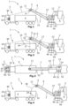
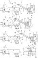
- the Figure 1 shows the system 1 comprising construction machine 2, transport vehicle 3 with loading space 4 and image recording device 5.
- the image recording device 5 is arranged on the construction machine 2 and aligned at least with the loading space 4 of the transport vehicle 3.
- the construction machine 2 has, as a conveyor device 6, a conveyor belt 7 which is pivotably arranged on the machine frame 8 of the construction machine 2.
- the image recording device 5 has one or more cameras 11 for recording data .
- the image recording device 5 is arranged at the uppermost end of the conveyor belt 7 such that the camera lens 9 of the camera 11 is directed downwards such that the viewing angle 10 covers the entire loading space 4 of the transport vehicle 3 and part of the construction machine 2.
- the milling machine or the machine frame 8 can be adjusted in height relative to the floor covering.
- the machine frame 8 is adjusted in height and thus the milling drum mounted in the machine frame 8 and not shown is also adjusted in height.
- the milling drum can be adjustable in height relative to the machine frame 8.
- the image recording device 5 can also capture a license plate, for example, the license plate number of the transport vehicle. Information about the license plate can also be sent to the receiving and display device via the transmitting device 46.
- the transmitting device 46 can send further data to the receiving and display device 18 in addition to the data recorded by the image recording device.
- the further data may be other machine information, in particular data concerning the milled material and/or messages from the driver of the construction machine 2 to the driver of the transport vehicle 3, preferably start or stop signals specified by the driver of the construction machine 2 for the driver of the transport vehicle 3.
- the receiving and display device 18 can have a second transmitting device 50 and a second receiving device 51 can be arranged on the construction machine 2 so that messages can be sent from the driver of the transport vehicle 3 to the driver of the construction machine 2 by the second transmitting device 50. Messages can thus be exchanged between the transport vehicle driver and the construction machine driver.
- the second transmitting device 50 and the receiving and display device can be configured as a unit.
- the second receiving device and the transmitting device 46 can also be configured as a unit.
- the system 1 can have an evaluation unit 13 for evaluating the data recorded with the image recording device 5, for example with an image analysis unit 14.
- the evaluation unit 13 can determine the fill level in the loading space and/or the distance between the construction machine 2 and the transport vehicle 3 and/or the point of impact of material in the loading space 4 by evaluating the image data.
- an impending collision between construction machine 2 and transport vehicle 3 can be determined.
- the impact point of the material can be the actual impact point of the material in the loading space 4 or, when the conveyor system is switched off, the potential impact point in the loading space 4 when the conveyor belt 6 is driven again.
- Other parameters such as the inclination of the conveyor belt 6, can also be taken into account.
- the further data which are sent from the transmitting device 46 to the receiving and display device 18 in addition to the data recorded by the image recording device 5 can be determined by the evaluation unit 13 Data, in particular start or stop signals for the driver of the transport vehicle 3 and/or mass of the milled material loaded and/or collision warning.
- the evaluation unit 13 can determine a start or stop signal which is sent via the transmitting device 45 to the receiving and display device 18.
- the camera lens 9 is preferably a wide-angle lens of a camera 11, which acts as a video camera and records an original image stream 12.
- the recorded data can be transmitted to the evaluation unit 13.
- an infrared camera and/or a stereoscopic camera and/or a PMD camera can also be used.
- the camera 11 is attached to the conveyor belt 7 of the conveyor device 6 in such a way that the orientation always points directly downwards, regardless of the inclination angle 27 of the conveyor belt relative to the machine frame 8 of the construction machine 2. This ensures that the camera always covers the loading area and the Part of the conveyor belt where the loading space 4 of the transport vehicle 3 could collide with the conveyor device 6.
- a first storage device 52 can be arranged on the construction machine 2, and/or the receiving and display device 18 can have a second storage device 53.
- the data recorded by the image recording device 5 and/or the further data transmitted to the receiving and display device 18 in addition to the data recorded by the image recording device 5 can be stored in the first and/or second storage devices 52, 53.
- a preferred embodiment provides for the receiving and display device 18 to be a portable computer, preferably a mobile phone.
- a mobile phone has the advantage that it can be carried by every transport vehicle driver, eliminating the need to provide a separate receiving and display device 18 for each transport vehicle.
- An application program can be installed on such a mobile phone, with the aid of which the data from the transmitting device can be received and displayed on the mobile phone monitor.
- the transport vehicle driver receives the information whether he must move or stop the vehicle via the receiving and display device 18.
- the transport vehicle driver receives information from the construction machine operator or from the evaluation unit 13 as to whether the transport vehicle should be moved or not, for example in the form of start/stop signals. He can also receive information about what type of material has been loaded, whether the maximum weight has been reached, and whether a collision with the construction machine is imminent. In this way, coordination between the transport vehicle and the construction machine can be significantly improved.
- signaling can be provided acoustically, for example by a horn 15.
- the Figure 2 shows how the camera 11 can be used to observe both the loading space 4 and the particularly critical point on the conveyor device 6, in order to, on the one hand, check that the loading area is properly filled and, on the other hand, to avoid a collision between the side wall 33 and the conveyor device 6.
- the loading process is particularly difficult when not only the transport vehicle 3 but also the construction machine 2 is movable.
- the construction machine 2 can pivot the conveyor 6, and the construction machine can be moved back and forth in alignment with the transport vehicle 3.
- Proper loading of the transport vehicle 3 therefore depends not only on the absolute position of the transport vehicle 3, but also on the relative position of the transport vehicle 3 to the conveyor 6 and the machine frame 8 of the construction machine 2.
- the vehicle driver always receives an image of the situation via the camera, which shows the transport vehicle 3 and in particular its loading area 4 in relation to the construction machine 2 and from the direction of the construction machine 2, in order to move the transport vehicle 3 into the correct position relative to the construction machine 2.
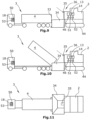
- FIGs 8 to 11 show the unloading of a transport vehicle3, in which the loading area 4 is first moved towards the construction machine 2, so that the loading area 4, as in Figure 9 shown, is positioned in front of a receiving container 34. The loading area 4 is then tilted so that bulk material flows into the receiving container 34.
- a camera 35 is positioned in the upper third of the construction machine 2 in such a way that it acts as an image recording device 36. with a wide-angle lens or multiple cameras that can display one or more image streams, as in Figure 3 shown, to an evaluation unit 13.
- a construction machine 2 For a construction machine 2 according to Figures 8 to 11 It is preferably a road paver.
- the road paver When the road paver is loaded with material, it moves slowly forward.
- the transport vehicle 3 slowly reverses towards the road paver until contact is established between the road paver and the transport vehicle 3.
- the transport vehicle 3 is then pushed in front of the road paver by the road paver, and the emptying takes place.
- the camera can also monitor both the loading area and the receiving container 34, in order to avoid a strong collision during the docking phase, particularly when the construction machine 2 and the transport vehicle 3 are moving, and to allow the material to slide into the trough of the receiving container 34 at different speeds. This is particularly advantageous when the construction machine transports the material at different speeds.
- the construction machine 2 according to the Figures 8 - 11 also preferably has an evaluation unit 13 with an image analysis program 14. Furthermore, a transmitting device 46, a receiving device 51 and a storage device 52 are preferably provided. These have the same functions as already for the construction machine according to Figures 1 to 7 described.
- the transport vehicle 3 can be used in the same way as the transport vehicle 3 according to the Figures 1 to 7 a receiving and display device 18, which may also have a transmitting device 50 and a storage device 53.
- the functions are the same as those according to Figures 1 to 7 described functions.
- message streams can be transmitted via the receiving and display device 18 and/or the second transmitting device 50 and the transmitting and receiving devices 46, 51 arranged on the construction machine. It is also advantageous if the message streams can be stored in one or both storage devices 52, 53.
- Reference images can be displayed on the monitor 19, at least on one image 20, 21, showing, for example, the optimal position of the transport vehicle 3 relative to the construction machine 2. This optimal position remains unchanged even when the transport vehicle 3 and the construction machine 2 are moving, since the optimal position of the transport vehicle remains unchanged from the perspective of the camera arranged on the construction machine 2, for example when docking with the construction machine 2. If the image 20, 21 deviates significantly from the displayed reference image, information can be sent to the receiving and display device 18 or a signal can be triggered, so that, for example, the horn 15 sounds.
Landscapes
- Engineering & Computer Science (AREA)
- Physics & Mathematics (AREA)
- Aviation & Aerospace Engineering (AREA)
- General Physics & Mathematics (AREA)
- Radar, Positioning & Navigation (AREA)
- Remote Sensing (AREA)
- Automation & Control Theory (AREA)
- Multimedia (AREA)
- Mechanical Engineering (AREA)
- Civil Engineering (AREA)
- Architecture (AREA)
- Structural Engineering (AREA)
- Signal Processing (AREA)
- Mining & Mineral Resources (AREA)
- Computer Vision & Pattern Recognition (AREA)
- Electromagnetism (AREA)
- Traffic Control Systems (AREA)
- Road Repair (AREA)
- Management, Administration, Business Operations System, And Electronic Commerce (AREA)
- Component Parts Of Construction Machinery (AREA)
Claims (10)
- Système (1) constitué d'une machine de chantier (2), d'un véhicule de transport (3) comportant un espace de chargement (4) et d'un dispositif de prise d'images (5, 36),dans lequel le dispositif de prise d'images (5, 36) est disposé sur la machine de chantier (2) et est orienté au moins vers l'espace de chargement (4) du véhicule de transport (3),dans lequelun dispositif de réception et d'affichage (18) est disposé sur le véhicule de transport (3) ou dans celui-ci, dans lequel les données enregistrées par le dispositif de prise d'images (5, 36) sont transmises au dispositif de réception et d'affichage (18) au moyen d'un dispositif d'émission (46) disposé sur la machine de chantier (2), dans lequel la machine de chantier (2) présente un dispositif d'acheminement (6),caractérisé en ce queles données enregistrées et transmises sont des données d'image et le dispositif de prise d'images (5, 36) présente au moins une caméra (11, 35) permettant d'enregistrer un flux d'images (12), dans lequelle dispositif de prise d'images (5, 36) est également orienté vers le dispositif d'acheminement (6), dans lequel tant l'espace de chargement (4) que le point particulièrement critique sur le dispositif d'acheminement (6) peuvent être observés avec la caméra (11) afin, d'une part, de contrôler le remplissage approprié de la plateforme de chargement et, d'autre part, d'éviter une collision entre un hayon (33) et le dispositif d'acheminement (6).
- Système (1) selon la revendication 1, caractérisé en ce que le système (1) présente une unité d'évaluation (13) comportant un programme d'analyse d'image (14) déterminant des données supplémentaires à partir des informations d'image.
- Système (1) selon la revendication 2, caractérisé en ce que l'unité d'évaluation (13) détermine le niveau de remplissage dans l'espace de chargement (4) et/ou la distance entre la machine de chantier (2) et le véhicule de transport (3) et/ou le point d'impact de matériau dans l'espace de chargement (4) en évaluant les données d'image.
- Système (1) selon la revendication 3, caractérisé en ce que d'autres données, lesquelles sont envoyées par le dispositif d'émission (46) au dispositif de réception et d'affichage (18) outre les données enregistrées par le dispositif de prise d'images (5, 36), sont des données déterminées par l'unité d'évaluation (13), en particulier des signaux de démarrage ou d'arrêt pour le conducteur du véhicule de transport et/ou une masse du fraisat chargé et/ou le volume du fraisat chargé sur le véhicule de transport et/ou le niveau de remplissage de l'espace de chargement (4) et/ou un avertissement de collision.
- Système selon la revendication 3 ou 4, caractérisé en ce que l'unité d'évaluation (13) détermine, en fonction du point d'impact du matériau dans l'espace de chargement (4) et/ou en fonction de la distance entre la machine de chantier et le véhicule de transport, un signal de démarrage ou d'arrêt qui est envoyé au dispositif de réception et d'affichage (18) par l'intermédiaire du dispositif d'émission.
- Procédé permettant l'affichage d'un flux d'images (12, 24, 25) dans un système selon l'une des revendications 1 à 5, dans lequel le procédé comprend les étapes suivantes lors du chargement ou du déchargement du véhicule de transport (3) :- enregistrement d'images (20, 21) avec un dispositif de prise d'images (5, 36), en particulier une caméra (11, 35), monté sur la machine de chantier (2) et orienté au moins vers l'espace de chargement (4) du véhicule de transport (3) ;- émission, réception et affichage des données enregistrées avec le dispositif de prise d'images sur un dispositif de réception et d'affichage (18) disposé sur le véhicule de transport (3) ou dans celui-ci.
- Procédé selon la revendication 6, caractérisé en ce qu'il présente l'étape suivante :- affichage simultané d'au moins deux flux d'images de sous-ensembles (24, 25) sur un moniteur (19) du dispositif de réception et d'affichage, dans lequel chaque flux d'images de sous-ensembles (24, 25) contient un sous-ensemble séparé d'images (20, 21) provenant du flux d'images (12).
- Procédé selon la revendication 6 ou 7, caractérisé en ce que les données enregistrées avec la caméra sont analysées avec une unité d'évaluation (13).
- Procédé selon la revendication 8, caractérisé en ce que le niveau de remplissage dans l'espace de chargement (4) et/ou la distance entre la machine de chantier (2) et le véhicule de transport (3) et/ou le point d'impact de matériau dans l'espace de chargement (4) sont déterminés au moyen de l'unité d'évaluation (13) en évaluant les données d'image.
- Procédé selon la revendication 8 ou 9, caractérisé en ce que d'autres données, lesquelles sont transmises au dispositif de réception et d'affichage (18) outre les données enregistrées par le dispositif de prise d'images (5, 36), en particulier par la caméra (11, 35), sont des données déterminées par l'unité d'évaluation (13), en particulier des signaux de démarrage ou d'arrêt pour le conducteur du véhicule de transport et/ou une masse du fraisat chargé et/ou un volume du fraisat chargé et/ou le niveau de remplissage dans l'espace de chargement (4) et/ou un avertissement de collision.
Applications Claiming Priority (3)
| Application Number | Priority Date | Filing Date | Title |
|---|---|---|---|
| DE102016000535 | 2016-01-21 | ||
| DE102016006303 | 2016-05-27 | ||
| PCT/EP2017/051340 WO2017125607A1 (fr) | 2016-01-21 | 2017-01-23 | Système comprenant un engin de chantier, un véhicule de transport doté d'un espace de chargement et un dispositif de prise de vue, et procédé pour afficher un courant d'images lors du chargement ou du déchargement d'un véhicule de transport |
Publications (3)
| Publication Number | Publication Date |
|---|---|
| EP3405419A1 EP3405419A1 (fr) | 2018-11-28 |
| EP3405419C0 EP3405419C0 (fr) | 2025-07-02 |
| EP3405419B1 true EP3405419B1 (fr) | 2025-07-02 |
Family
ID=57890801
Family Applications (1)
| Application Number | Title | Priority Date | Filing Date |
|---|---|---|---|
| EP17701464.4A Active EP3405419B1 (fr) | 2016-01-21 | 2017-01-23 | Système comprenant un engin de chantier, un véhicule de transport doté d'un espace de chargement et un dispositif de prise de vue, et procédé pour afficher un courant d'images lors du chargement ou du déchargement d'un véhicule de transport |
Country Status (4)
| Country | Link |
|---|---|
| US (4) | US11242003B2 (fr) |
| EP (1) | EP3405419B1 (fr) |
| CN (1) | CN108473260B (fr) |
| WO (1) | WO2017125607A1 (fr) |
Families Citing this family (18)
| Publication number | Priority date | Publication date | Assignee | Title |
|---|---|---|---|---|
| EP3405419B1 (fr) * | 2016-01-21 | 2025-07-02 | Wirtgen GmbH | Système comprenant un engin de chantier, un véhicule de transport doté d'un espace de chargement et un dispositif de prise de vue, et procédé pour afficher un courant d'images lors du chargement ou du déchargement d'un véhicule de transport |
| DE102016223454A1 (de) | 2016-11-25 | 2018-05-30 | Wirtgen Gmbh | System und Verfahren zum Nachverfolgen von Fräsgut |
| DE102016222145A1 (de) | 2016-11-11 | 2018-05-17 | Wirtgen Gmbh | System und Verfahren zum Nachverfolgen von Fräsgut |
| US10927513B2 (en) | 2016-11-11 | 2021-02-23 | Wirtgen Gmbh | System and method for the tracking of milling material |
| DE102016222589B4 (de) | 2016-11-16 | 2020-01-16 | Wirtgen Gmbh | Selbstfahrende Fräsmaschine, sowie Verfahren zum Steuern einer selbstfahrenden Fräsmaschine |
| CN108221610A (zh) * | 2018-03-14 | 2018-06-29 | 徐州徐工筑路机械有限公司 | 一种基于视觉识别的铣刨机自动输料系统 |
| US11001991B2 (en) * | 2019-01-11 | 2021-05-11 | Caterpillar Inc. | Optimizing loading of a payload carrier of a machine |
| DE102019104218A1 (de) | 2019-02-19 | 2020-08-20 | Wirtgen Gmbh | Arbeitszug, umfassend eine Bodenbearbeitungsmaschine und ein weiteres Fahrzeug sowie eine automatisierte Abstandsüberwachung |
| US11286123B2 (en) * | 2019-06-20 | 2022-03-29 | Dcl, Inc. | Camera-enabled loader system and method |
| CN111301259B (zh) * | 2020-04-10 | 2025-02-07 | 贵刚 | 一种运输车与载货车的自动对接装填系统、方法及计算机存储介质 |
| DE102020206370B4 (de) | 2020-05-20 | 2022-10-06 | Robert Bosch Gesellschaft mit beschränkter Haftung | Verfahren zum Ausgeben eines Signals in Abhängigkeit einer ermittelten maximalen Ladekapazität eines Transportfahrzeugs für Schüttgut |
| DE102020206374A1 (de) | 2020-05-20 | 2021-11-25 | Robert Bosch Gesellschaft mit beschränkter Haftung | Verfahren zur Steuerung eines Beladevorgangs einer Ladefläche eines Transportfahrzeugs zum Transport von Schüttgut |
| US11730328B2 (en) | 2020-08-14 | 2023-08-22 | Irobot Corporation | Visual fiducial for behavior control zone |
| TWI804962B (zh) * | 2021-08-27 | 2023-06-11 | 林德誠 | 運輸車之行車影像系統、行車影像處理裝置及其方法 |
| CN116086577A (zh) * | 2023-01-09 | 2023-05-09 | 山西明洋易自动化设备有限公司 | 一种基于激光雷达和摄像装置的挖掘机称重系统 |
| DE102023201764A1 (de) * | 2023-02-27 | 2024-08-29 | Bomag Gmbh | Verfahren zur zählung von transportfahrzeugen, die in eine beladeposition relativ zu einer bodenfräsmaschine gelangen, sowie bodenfräsmaschine |
| US12540834B2 (en) | 2023-04-12 | 2026-02-03 | Deere & Company | Automated recognition and performance of vehicle to camera calibration |
| US12596384B2 (en) | 2024-03-05 | 2026-04-07 | Deere & Company | System and method for mapping obstructions in a work area to corresponding locations |
Citations (1)
| Publication number | Priority date | Publication date | Assignee | Title |
|---|---|---|---|---|
| DE19647522A1 (de) * | 1996-11-16 | 1998-05-20 | Claas Ohg | Vorrichtung zur Überwachung der Überladung von Gütern von einer Arbeitsmaschine auf ein Transportfahrzeug |
Family Cites Families (25)
| Publication number | Priority date | Publication date | Assignee | Title |
|---|---|---|---|---|
| JPH04122711A (ja) | 1990-09-14 | 1992-04-23 | Ube Ind Ltd | ポリブタジエンの重合方法 |
| JPH0747446Y2 (ja) * | 1991-04-18 | 1995-11-01 | 株式会社新潟鉄工所 | アスファルトフィニッシャにおけるダンプカーの誘導装置 |
| DE9402324U1 (de) * | 1994-02-11 | 1995-06-14 | Joseph Vögele AG, 68163 Mannheim | Straßenfertiger |
| WO1999051789A1 (fr) | 1998-04-01 | 1999-10-14 | Nkk Corporation | Procede de zingage par immersion a chaud et dispositif afferent |
| DE102006055344A1 (de) * | 2006-11-23 | 2008-05-29 | Vdo Automotive Ag | Verfahren zur drahtlosen Kommunikation zwischen Fahrzeugen |
| DE202007005756U1 (de) | 2007-04-19 | 2008-08-28 | Wirtgen Gmbh | Selbstfahrende Baumaschine |
| EP2020174B1 (fr) * | 2007-08-03 | 2012-02-29 | AGROCOM GmbH & Co. Agrarsystem KG | Machine de travail agricole |
| US8099218B2 (en) * | 2007-11-30 | 2012-01-17 | Caterpillar Inc. | Paving system and method |
| DE102008008260B4 (de) | 2008-02-08 | 2010-09-09 | Wirtgen Gmbh | Steuerung einer Gewinnungsmaschine und Gewinnungsmaschine |
| PL2311307T3 (pl) * | 2009-09-07 | 2012-09-28 | Claas E Systems Gmbh | Wskaźnik stopnia napełnienia, pojazd rolniczy zawierający taki wskaźnik oraz sposób kontroli napełniania obszaru docelowego |
| DE102011002071A1 (de) * | 2011-04-15 | 2012-10-18 | Claas Selbstfahrende Erntemaschinen Gmbh | System und Verfahren zur Steuerung der Erntegutüberladung |
| EP2515255A1 (fr) * | 2011-04-18 | 2012-10-24 | Joseph Vögele AG | Appareil de lecture portable pour la caractérisation d'un engin de chantier |
| DE102011114183A1 (de) * | 2011-09-22 | 2013-03-28 | Bomag Gmbh | Verfahren zur Steuerung eines Beladungsvorgangs eines Transportfahrzeugs mit Fräsgut, Vorrichtung zur Durchführung eines solchen Verfahrens und Fräsvorrichtung |
| JP5938222B2 (ja) * | 2012-02-07 | 2016-06-22 | 日立建機株式会社 | 運搬車両の周囲監視装置 |
| DE102012215005A1 (de) | 2012-08-23 | 2014-02-27 | Wirtgen Gmbh | Selbstfahrende Fräsmaschine, sowie Verfahren zum Lenken einer selbstfahrenden Fräsmaschine |
| DE102012215013A1 (de) | 2012-08-23 | 2014-02-27 | Wirtgen Gmbh | Selbstfahrende Fräsmaschine, sowie Verfahren zum Abladen von Fräsgut |
| DE102014216603B4 (de) | 2014-08-21 | 2018-02-22 | Wirtgen Gmbh | Selbstfahrende Fräsmaschine, sowie Verfahren zum Abladen von Fräsgut |
| DE102014216763B4 (de) | 2014-08-22 | 2018-07-26 | Wirtgen Gmbh | Selbstfahrende Fräsmaschine, sowie Verfahren zum Abladen von Fräsgut |
| DE102014216713B4 (de) | 2014-08-22 | 2018-09-06 | Wirtgen Gmbh | Selbstfahrende Fräsmaschine, sowie Verfahren zum Abladen von Fräsgut |
| US9957675B2 (en) * | 2015-07-10 | 2018-05-01 | Caterpillar Paving Products Inc. | Cold planer loading and transport control system |
| EP3405419B1 (fr) * | 2016-01-21 | 2025-07-02 | Wirtgen GmbH | Système comprenant un engin de chantier, un véhicule de transport doté d'un espace de chargement et un dispositif de prise de vue, et procédé pour afficher un courant d'images lors du chargement ou du déchargement d'un véhicule de transport |
| DE102016223454A1 (de) * | 2016-11-25 | 2018-05-30 | Wirtgen Gmbh | System und Verfahren zum Nachverfolgen von Fräsgut |
| DE102016222145A1 (de) * | 2016-11-11 | 2018-05-17 | Wirtgen Gmbh | System und Verfahren zum Nachverfolgen von Fräsgut |
| US10386866B2 (en) * | 2017-11-20 | 2019-08-20 | Caterpillar Paving Products Inc. | Automatic control of plunge velocity based on depth of cut |
| US20240351809A1 (en) * | 2023-04-21 | 2024-10-24 | Deere & Company | Perception system and method for fill level sensing and decision support |
-
2017
- 2017-01-23 EP EP17701464.4A patent/EP3405419B1/fr active Active
- 2017-01-23 CN CN201780007676.5A patent/CN108473260B/zh active Active
- 2017-01-23 WO PCT/EP2017/051340 patent/WO2017125607A1/fr not_active Ceased
- 2017-01-23 US US16/070,834 patent/US11242003B2/en active Active
-
2022
- 2022-02-01 US US17/590,425 patent/US11787337B2/en active Active
-
2023
- 2023-08-21 US US18/452,763 patent/US12227906B2/en active Active
-
2025
- 2025-02-12 US US19/051,610 patent/US20250250748A1/en active Pending
Patent Citations (1)
| Publication number | Priority date | Publication date | Assignee | Title |
|---|---|---|---|---|
| DE19647522A1 (de) * | 1996-11-16 | 1998-05-20 | Claas Ohg | Vorrichtung zur Überwachung der Überladung von Gütern von einer Arbeitsmaschine auf ein Transportfahrzeug |
Also Published As
| Publication number | Publication date |
|---|---|
| US20250250748A1 (en) | 2025-08-07 |
| US11787337B2 (en) | 2023-10-17 |
| WO2017125607A1 (fr) | 2017-07-27 |
| CN108473260A (zh) | 2018-08-31 |
| US20190061623A1 (en) | 2019-02-28 |
| EP3405419C0 (fr) | 2025-07-02 |
| US20220324382A1 (en) | 2022-10-13 |
| EP3405419A1 (fr) | 2018-11-28 |
| CN108473260B (zh) | 2022-08-12 |
| US12227906B2 (en) | 2025-02-18 |
| US11242003B2 (en) | 2022-02-08 |
| US20240042929A1 (en) | 2024-02-08 |
Similar Documents
| Publication | Publication Date | Title |
|---|---|---|
| EP3405419B1 (fr) | Système comprenant un engin de chantier, un véhicule de transport doté d'un espace de chargement et un dispositif de prise de vue, et procédé pour afficher un courant d'images lors du chargement ou du déchargement d'un véhicule de transport | |
| EP2573267B1 (fr) | Train de traveaux avec un dispositif de fraisage et une installation de transport et un dispositif de capteur pour la surveillance à distance, dispositif de fraisage avec un dispositif de capteur et procédé de surveillance à distance avec un train de traveaux | |
| EP2573266B1 (fr) | Procédé de commande d'un procédé de chargement d'un véhicule de transport avec des produits de fraisage, dispositif destiné à réaliser un tel procédé et dispositif de fraisage | |
| EP1302076B1 (fr) | Dispositif et procede pour surveiller l'environnement d'un objet | |
| EP3135822B1 (fr) | Engin automobile et procede d'affichage de l'environnement d'un engin automobile | |
| DE102007033808B4 (de) | Selbstfahrende Großfräse | |
| DE102005018773B4 (de) | Vorrichtung zur Sicht der Umgebung eines Fahrzeugs | |
| EP3323940B1 (fr) | Fraiseuse automotrice et procédé de commande d'une fraiseuse automotrice | |
| EP4001507B1 (fr) | Procédé de commande du fonctionnement d'une bande transporteuse de chargement pour marchandises en vrac disposée sur une machine autonome de construction de route ou d'exploitation minière de surface par rapport à un benne d'un véhicule de transport, ainsi que machine de construction de route ou d'exploitation minière de surface destinée à la mise en oeuvre du procédé | |
| EP3543402B1 (fr) | Engin de construction permettant de construire ou de travailler une route | |
| EP0843960A1 (fr) | Dispositif pour contrÔler le transbordement de marchandises d'une machine de travail à un véhicule de transport | |
| DE102022203042A1 (de) | System und verfahren zur beladungsunterstützung für arbeitsmaschinen | |
| DE102014216763A1 (de) | Selbstfahrende Fräsmaschine, sowie Verfahren zum Abladen von Fräsgut | |
| DE112016004648T5 (de) | Lastkraftwagenpositionskontrollsystem für fräsvorgänge | |
| DE112013000873T5 (de) | Peripherieüberwachungsvorrichtung für Transportfahrzeug | |
| EP3872258B1 (fr) | Transfert de matière sans contact entre un poids lourd et un véhicule mobile pour travaux routiers | |
| DE102023113630A1 (de) | Erweitertes maschinenbenutzeroberflächensystem | |
| EP3064646A1 (fr) | Machine de construction de routes et procédé de fonctionnement d'une machine de construction de routes | |
| DE102017220869A1 (de) | Selbstfahrende Fräsmaschine, Verfahren zum automatischen Beladen eines Transportmittels mit Fräsgut, sowie Straßen- oder Bodenbearbeitungseinheit | |
| EP3260606B1 (fr) | Équipement interchangeable pour une machine de travail et machine de travail comprenant un tel équipement | |
| EP3858670A1 (fr) | Machine de construction pourvue de dispositif d'éclairage | |
| DE102023201764A1 (de) | Verfahren zur zählung von transportfahrzeugen, die in eine beladeposition relativ zu einer bodenfräsmaschine gelangen, sowie bodenfräsmaschine | |
| DE102017011159A1 (de) | Straßenbaumaschine und Verfahren zum Betreiben einer Straßenbaumaschine | |
| DE112023004057T5 (de) | Strassenmaschine und strassenoberflächenpflastersystem | |
| DE102022205561A1 (de) | VERFAHREN ZUM BEFÜLLEN EINES TRANSPORTBEHÄLTERS MIT FRÄSGUT IN EINEM ARBEITSZUG MIT EINER STRAßENFRÄSMASCHINE UND EINEM TRANSPORTFAHRZEUG, ARBEITZUG, STRAßENFRÄSMASCHINE, TRANSPORTFAHRZEUG UND NACHRÜSTSATZ |
Legal Events
| Date | Code | Title | Description |
|---|---|---|---|
| STAA | Information on the status of an ep patent application or granted ep patent |
Free format text: STATUS: UNKNOWN |
|
| STAA | Information on the status of an ep patent application or granted ep patent |
Free format text: STATUS: THE INTERNATIONAL PUBLICATION HAS BEEN MADE |
|
| PUAI | Public reference made under article 153(3) epc to a published international application that has entered the european phase |
Free format text: ORIGINAL CODE: 0009012 |
|
| STAA | Information on the status of an ep patent application or granted ep patent |
Free format text: STATUS: REQUEST FOR EXAMINATION WAS MADE |
|
| 17P | Request for examination filed |
Effective date: 20180816 |
|
| AK | Designated contracting states |
Kind code of ref document: A1 Designated state(s): AL AT BE BG CH CY CZ DE DK EE ES FI FR GB GR HR HU IE IS IT LI LT LU LV MC MK MT NL NO PL PT RO RS SE SI SK SM TR |
|
| AX | Request for extension of the european patent |
Extension state: BA ME |
|
| DAV | Request for validation of the european patent (deleted) | ||
| DAX | Request for extension of the european patent (deleted) | ||
| STAA | Information on the status of an ep patent application or granted ep patent |
Free format text: STATUS: EXAMINATION IS IN PROGRESS |
|
| 17Q | First examination report despatched |
Effective date: 20201223 |
|
| P01 | Opt-out of the competence of the unified patent court (upc) registered |
Effective date: 20230527 |
|
| GRAP | Despatch of communication of intention to grant a patent |
Free format text: ORIGINAL CODE: EPIDOSNIGR1 |
|
| STAA | Information on the status of an ep patent application or granted ep patent |
Free format text: STATUS: GRANT OF PATENT IS INTENDED |
|
| RIC1 | Information provided on ipc code assigned before grant |
Ipc: E01C 19/48 20060101ALI20250127BHEP Ipc: G05D 1/00 20060101ALI20250127BHEP Ipc: E01C 23/088 20060101ALI20250127BHEP Ipc: B65G 67/22 20060101AFI20250127BHEP |
|
| INTG | Intention to grant announced |
Effective date: 20250220 |
|
| GRAS | Grant fee paid |
Free format text: ORIGINAL CODE: EPIDOSNIGR3 |
|
| GRAA | (expected) grant |
Free format text: ORIGINAL CODE: 0009210 |
|
| STAA | Information on the status of an ep patent application or granted ep patent |
Free format text: STATUS: THE PATENT HAS BEEN GRANTED |
|
| AK | Designated contracting states |
Kind code of ref document: B1 Designated state(s): AL AT BE BG CH CY CZ DE DK EE ES FI FR GB GR HR HU IE IS IT LI LT LU LV MC MK MT NL NO PL PT RO RS SE SI SK SM TR |
|
| REG | Reference to a national code |
Ref country code: GB Ref legal event code: FG4D Free format text: NOT ENGLISH |
|
| REG | Reference to a national code |
Ref country code: CH Ref legal event code: EP |
|
| REG | Reference to a national code |
Ref country code: DE Ref legal event code: R096 Ref document number: 502017016931 Country of ref document: DE |
|
| REG | Reference to a national code |
Ref country code: IE Ref legal event code: FG4D Free format text: LANGUAGE OF EP DOCUMENT: GERMAN |
|
| U01 | Request for unitary effect filed |
Effective date: 20250730 |
|
| U07 | Unitary effect registered |
Designated state(s): AT BE BG DE DK EE FI FR IT LT LU LV MT NL PT RO SE SI Effective date: 20250805 |
|
| PG25 | Lapsed in a contracting state [announced via postgrant information from national office to epo] |
Ref country code: IS Free format text: LAPSE BECAUSE OF FAILURE TO SUBMIT A TRANSLATION OF THE DESCRIPTION OR TO PAY THE FEE WITHIN THE PRESCRIBED TIME-LIMIT Effective date: 20251102 |
|
| PG25 | Lapsed in a contracting state [announced via postgrant information from national office to epo] |
Ref country code: NO Free format text: LAPSE BECAUSE OF FAILURE TO SUBMIT A TRANSLATION OF THE DESCRIPTION OR TO PAY THE FEE WITHIN THE PRESCRIBED TIME-LIMIT Effective date: 20251002 |
|
| PG25 | Lapsed in a contracting state [announced via postgrant information from national office to epo] |
Ref country code: HR Free format text: LAPSE BECAUSE OF FAILURE TO SUBMIT A TRANSLATION OF THE DESCRIPTION OR TO PAY THE FEE WITHIN THE PRESCRIBED TIME-LIMIT Effective date: 20250702 |
|
| PG25 | Lapsed in a contracting state [announced via postgrant information from national office to epo] |
Ref country code: GR Free format text: LAPSE BECAUSE OF FAILURE TO SUBMIT A TRANSLATION OF THE DESCRIPTION OR TO PAY THE FEE WITHIN THE PRESCRIBED TIME-LIMIT Effective date: 20251003 |
|
| PG25 | Lapsed in a contracting state [announced via postgrant information from national office to epo] |
Ref country code: CZ Free format text: LAPSE BECAUSE OF FAILURE TO SUBMIT A TRANSLATION OF THE DESCRIPTION OR TO PAY THE FEE WITHIN THE PRESCRIBED TIME-LIMIT Effective date: 20250702 |
|
| PG25 | Lapsed in a contracting state [announced via postgrant information from national office to epo] |
Ref country code: PL Free format text: LAPSE BECAUSE OF FAILURE TO SUBMIT A TRANSLATION OF THE DESCRIPTION OR TO PAY THE FEE WITHIN THE PRESCRIBED TIME-LIMIT Effective date: 20250702 |
|
| PG25 | Lapsed in a contracting state [announced via postgrant information from national office to epo] |
Ref country code: RS Free format text: LAPSE BECAUSE OF FAILURE TO SUBMIT A TRANSLATION OF THE DESCRIPTION OR TO PAY THE FEE WITHIN THE PRESCRIBED TIME-LIMIT Effective date: 20251002 |
|
| PG25 | Lapsed in a contracting state [announced via postgrant information from national office to epo] |
Ref country code: ES Free format text: LAPSE BECAUSE OF FAILURE TO SUBMIT A TRANSLATION OF THE DESCRIPTION OR TO PAY THE FEE WITHIN THE PRESCRIBED TIME-LIMIT Effective date: 20250702 |
|
| U20 | Renewal fee for the european patent with unitary effect paid |
Year of fee payment: 10 Effective date: 20260128 |
|
| PG25 | Lapsed in a contracting state [announced via postgrant information from national office to epo] |
Ref country code: SM Free format text: LAPSE BECAUSE OF FAILURE TO SUBMIT A TRANSLATION OF THE DESCRIPTION OR TO PAY THE FEE WITHIN THE PRESCRIBED TIME-LIMIT Effective date: 20250702 |
|
| PG25 | Lapsed in a contracting state [announced via postgrant information from national office to epo] |
Ref country code: SK Free format text: LAPSE BECAUSE OF FAILURE TO SUBMIT A TRANSLATION OF THE DESCRIPTION OR TO PAY THE FEE WITHIN THE PRESCRIBED TIME-LIMIT Effective date: 20250702 |