EP3405656B1 - Bläsermodul eines luftfahrzeug-turbinentriebs mit einer vorrichtung zum enteisen eines splitters und eintrittsleitschaufeln - Google Patents
Bläsermodul eines luftfahrzeug-turbinentriebs mit einer vorrichtung zum enteisen eines splitters und eintrittsleitschaufeln Download PDFInfo
- Publication number
- EP3405656B1 EP3405656B1 EP17702678.8A EP17702678A EP3405656B1 EP 3405656 B1 EP3405656 B1 EP 3405656B1 EP 17702678 A EP17702678 A EP 17702678A EP 3405656 B1 EP3405656 B1 EP 3405656B1
- Authority
- EP
- European Patent Office
- Prior art keywords
- hook
- annular wall
- hot air
- guide vanes
- inlet guide
- Prior art date
- Legal status (The legal status is an assumption and is not a legal conclusion. Google has not performed a legal analysis and makes no representation as to the accuracy of the status listed.)
- Active
Links
Images

Classifications
-
- F—MECHANICAL ENGINEERING; LIGHTING; HEATING; WEAPONS; BLASTING
- F01—MACHINES OR ENGINES IN GENERAL; ENGINE PLANTS IN GENERAL; STEAM ENGINES
- F01D—NON-POSITIVE DISPLACEMENT MACHINES OR ENGINES, e.g. STEAM TURBINES
- F01D25/00—Component parts, details, or accessories, not provided for in, or of interest apart from, other groups
- F01D25/02—De-icing means for engines having icing phenomena
-
- F—MECHANICAL ENGINEERING; LIGHTING; HEATING; WEAPONS; BLASTING
- F01—MACHINES OR ENGINES IN GENERAL; ENGINE PLANTS IN GENERAL; STEAM ENGINES
- F01D—NON-POSITIVE DISPLACEMENT MACHINES OR ENGINES, e.g. STEAM TURBINES
- F01D25/00—Component parts, details, or accessories, not provided for in, or of interest apart from, other groups
- F01D25/24—Casings; Casing parts, e.g. diaphragms, casing fastenings
- F01D25/246—Fastening of diaphragms or stator-rings
-
- F—MECHANICAL ENGINEERING; LIGHTING; HEATING; WEAPONS; BLASTING
- F02—COMBUSTION ENGINES; HOT-GAS OR COMBUSTION-PRODUCT ENGINE PLANTS
- F02C—GAS-TURBINE PLANTS; AIR INTAKES FOR JET-PROPULSION PLANTS; CONTROLLING FUEL SUPPLY IN AIR-BREATHING JET-PROPULSION PLANTS
- F02C7/00—Features, components parts, details or accessories, not provided for in, or of interest apart form groups F02C1/00 - F02C6/00; Air intakes for jet-propulsion plants
- F02C7/04—Air intakes for gas-turbine plants or jet-propulsion plants
- F02C7/047—Heating to prevent icing
-
- F—MECHANICAL ENGINEERING; LIGHTING; HEATING; WEAPONS; BLASTING
- F02—COMBUSTION ENGINES; HOT-GAS OR COMBUSTION-PRODUCT ENGINE PLANTS
- F02K—JET-PROPULSION PLANTS
- F02K3/00—Plants including a gas turbine driving a compressor or a ducted fan
- F02K3/02—Plants including a gas turbine driving a compressor or a ducted fan in which part of the working fluid by-passes the turbine and combustion chamber
- F02K3/04—Plants including a gas turbine driving a compressor or a ducted fan in which part of the working fluid by-passes the turbine and combustion chamber the plant including ducted fans, i.e. fans with high volume, low pressure outputs, for augmenting the jet thrust, e.g. of double-flow type
- F02K3/06—Plants including a gas turbine driving a compressor or a ducted fan in which part of the working fluid by-passes the turbine and combustion chamber the plant including ducted fans, i.e. fans with high volume, low pressure outputs, for augmenting the jet thrust, e.g. of double-flow type with front fan
-
- B—PERFORMING OPERATIONS; TRANSPORTING
- B64—AIRCRAFT; AVIATION; COSMONAUTICS
- B64D—EQUIPMENT FOR FITTING IN OR TO AIRCRAFT; FLIGHT SUITS; PARACHUTES; ARRANGEMENT OR MOUNTING OF POWER PLANTS OR PROPULSION TRANSMISSIONS IN AIRCRAFT
- B64D33/00—Arrangement in aircraft of power plant parts or auxiliaries not otherwise provided for
- B64D33/02—Arrangement in aircraft of power plant parts or auxiliaries not otherwise provided for of combustion air intakes
- B64D2033/0233—Arrangement in aircraft of power plant parts or auxiliaries not otherwise provided for of combustion air intakes comprising de-icing means
-
- F—MECHANICAL ENGINEERING; LIGHTING; HEATING; WEAPONS; BLASTING
- F05—INDEXING SCHEMES RELATING TO ENGINES OR PUMPS IN VARIOUS SUBCLASSES OF CLASSES F01-F04
- F05D—INDEXING SCHEME FOR ASPECTS RELATING TO NON-POSITIVE-DISPLACEMENT MACHINES OR ENGINES, GAS-TURBINES OR JET-PROPULSION PLANTS
- F05D2240/00—Components
- F05D2240/10—Stators
- F05D2240/12—Fluid guiding means, e.g. vanes
- F05D2240/121—Fluid guiding means, e.g. vanes related to the leading edge of a stator vane
Definitions
- the present invention relates to the general field of turbomachinery.
- the invention relates more particularly to a system for defrosting a separation nozzle and fixed inlet vanes of the primary stream of the turbomachine.
- the flow streams of the primary flow and the secondary flow are separated downstream of the fan by a separation nozzle.
- a separation nozzle Within the primary stream, at the inlet of the low pressure compressor (also commonly called a “booster"), there is a set of fixed inlet guide vanes (also called IGV for "Inlet Guide Vane”).
- icing atmospheric conditions may be encountered by the turbomachine, in particular when the ambient temperature is sufficiently low and in the presence of high humidity.
- ice may form on the separation spout and the inlet guide vanes.
- An obstruction of the primary vein causes the combustion chamber to be underpowered, which can then shut down or prevent the engine from accelerating. If ice blocks are detached, they can damage the downstream compressor and also lead to the combustion chamber being extinguished.
- the main object of the present invention is therefore to propose a device for defrosting a separation spout and inlet guide vanes which allows improved defrosting of the separation spout and inlet guide vanes for the primary vein.
- the hook comprises an external surface facing the external annular wall forming an angle of less than 90 ° with the axis of an injection orifice so that the external surface of the hook progressively approaches the annular wall outside by moving away from said injection orifice, the external surface of the hook having a minimum clearance J with the external annular wall such that: 0.2 ⁇ J / D ⁇ 0.6; where D is the hydraulic diameter of the injection orifice.
- upstream and downstream are defined with respect to the direction of flow of the air inside the turbomachine; the terms “interior” and “exterior”, “axial” and “radial”, and their derivatives, are defined with respect to the longitudinal axis of the turbomachine.
- the device according to the invention makes it possible to simultaneously and with the same flow of hot air, defrost the separation nozzle and the inlet guide vanes.
- the angle less than 90 ° between the external surface of the hook and the axis of an injection orifice, and the orientation of said surface allows the existence of a minimum clearance between the hook and the external annular wall of the separation spout.
- This minimal clearance makes it possible to accelerate the flow of hot air which arrives inside the separation nozzle upstream.
- This acceleration of the hot air flow inside the spout increases the speed of impact of the hot air flow on the end of the separation spout, which improves its defrosting.
- the shape of the hook according to the invention allows a better distribution of the hot air flow in azimuth, that is to say along the separation nozzle and around the longitudinal axis of the turbomachine.
- the flow of hot air is generally concentrated around the holes, which causes inhomogeneous defrosting of the separation spout.
- the bores can be separated and distant from the hook and can thus be positioned more upstream of the inlet guide vanes than in the devices of the prior art.
- the hot air jets have more distance to enter the vein and defrost the inlet guide vanes to a greater depth in the vein.
- the device according to the invention makes it possible, for the same flow of hot air taken from the engine, to obtain better defrosting of the separation nozzle and better penetration of the hot air jets into the vein than with the devices of the prior art.
- studies have notably shown an increase in the penetration of jets into the vein up to 50% more than with the devices of the prior art based on hot air jets.
- the hook is axisymmetric around a longitudinal axis of the turbomachine.
- the external surface of the hook forms an angle between 40 ° and 70 ° with the axis of an injection orifice.
- the angle with which each jet of hot air enters the primary vein is such that the jet is more inclined upstream than with an angle outside this range of values. This arrangement further increases the penetration of the hot air jet into the vein and improves the defrosting of the inlet guide vanes.
- the hydraulic diameter D of an injection orifice respects the following inequality: 2% ⁇ D / H ⁇ 6%, where H is the distance between the injection orifice and an interior wall of the channel d flow of the primary flow.
- the distance H also corresponds to the height of the flow stream of the primary flow at the injection orifices.
- This range of values ensures that the jet of hot air in the flow is adapted to the dimensions of the compressor. Indeed, for values of D / H ⁇ 2%, the flow of hot air leaving the orifice is too low to ensure correct defrosting.
- D / H> 6% the section of an orifice is larger and the jet generated is characterized by a low Mach number, which causes rapid shearing of the jet by the flow of the primary flow in the vein.
- each injection orifice can have a circular section.
- the device may further comprise means for conveying hot air configured to deliver hot air upstream inside the separation spout.
- the invention also relates to an aeronautical turbomachine blower module comprising: a blower, a low pressure compressor, inlet guide vanes located upstream of the compressor low pressure and downstream of the blower, and a defrosting device such as that presented above, the injection orifices being positioned on the inner annular wall of the separation nozzle so that in operation, the hot air delivered through each injection orifice in the flow channel of the primary flow is ejected towards a leading edge of an inlet guide vane.
- the invention also relates to an aeronautical turbomachine comprising a fan module such as that presented above.
- the figure 1 partially represents an aeronautical turbomachine 1 of the double-body and double-flow type to which the invention can be applied.
- the turbomachine 1 is axisymmetric with respect to a longitudinal axis XX and comprises an inlet at its upstream end which receives outside air, this air coming to supply a fan 2. Downstream of the fan 2, l air is distributed between a flow stream (or channel) of a primary flow 4 (or hot flow) and a flow stream of a secondary flow 6 (or cold flow). These two veins 4, 6 are separated from each other at their entry by a separation nozzle 8.
- a low pressure compressor 3 or "booster”
- boost high pressure compressor
- combustion chamber and turbines these latter elements are not shown in the figures
- the separation spout 8 has a U or V-shaped longitudinal section rounded at its upstream end, and comprises an inner annular wall 10 delimiting the entry of the flow stream of the primary flow 4, and an outer annular wall 12 delimiting inside the flow stream of the secondary flow 6.
- the outer annular wall 12 has a dimension in the longitudinal direction greater than that of the inner annular wall 10.
- the inner annular wall 12 of the separation spout 8 includes holes forming hot air injection holes 14 in the flow stream of the primary flow 4 having a drilling axis A.
- the injection holes 14 are distributed circumferentially around the inner annular wall 10.
- the axis A of each orifice 14 is here substantially radial with respect to the axis XX of the turbomachine, that is to say that the axis A is substantially perpendicular to the axis XX.
- the injection orifices 14 are separated by a distance H from the wall 15 delimiting the flow stream of the primary flow inside (the distance H also corresponds to the height of the stream at the right of the injection orifices 14 ).
- the injection orifices 14 may be circular, as in the example illustrated, or for example oval. In all cases, they can have a hydraulic diameter D respecting the inequality 0.02 ⁇ D / H ⁇ 0.06.
- the hydraulic diameter is, in a manner known per se, defined for air as the ratio between four times the area of the passage section of an orifice and the perimeter of this orifice. In the case of an injection orifice 14 of circular section, the hydraulic diameter is equal to the diameter of the orifice.
- the inner annular wall 10 of the separation spout 8 is extended downstream by an internal ferrule 16.
- the internal ferrule 16 carries the fixed inlet guide vanes 18 of the turbomachine. It will be noted that the position of the injection orifices 14 can be chosen so that in operation, the hot air jets delivered by said orifices 14 impact the leading edge of the inlet guide vanes 18 in the flow stream of the primary flow.
- the inner 10 and outer 12 annular walls, and the inner ferrule 16, define an annular cavity 20 to inside the separation spout 8.
- the internal ferrule 16 is mounted and blocked upstream on the internal annular wall 10 of the separation spout 8 by a hook 22 integrated into said ferrule 16, and downstream on a casing structural 24 of the turbomachine.
- the structural casing 24 comprises an internal casing 26 extending the internal ferrule 16 downstream, and on which the internal ferrule 16 comes to bear; and an external casing 28 provided with a flange 30 intended to cooperate with a flange 32 present at the downstream end of the internal ferrule 16.
- the internal 26 and external 28 casings define between them an annular channel for conveying hot air 34 opening into the cavity 20 of the separation spout 8 by means of openings 36 present in the flange 32 of the internal shroud 16.
- Hot air injectors (not shown) make it possible to introduce hot air taken off for example in a compressor of the turbomachine inside the annular hot air channel 34.
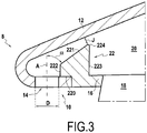
- the hook 22 upstream of the internal ferrule 16 is shown in more detail on the figure 3 .
- the hook 22 comprises an internal surface 220 resting on the internal annular wall 10 of the separation spout 8, and an external surface 221 facing the external annular wall 12 of the spout 8.
- the hook 22 further comprises an upstream surface 222 and a downstream surface 223 which are here substantially parallel to one another, and which here extend in a substantially radial direction.
- the upstream surface 222 of the hook 22 provides the connection between the interior surface 220 and the exterior surface 221 upstream.
- the upstream surface 222 is here smaller than the downstream surface 223.
- the surfaces 220, 221, 222 and 223 of the hook 22 are here substantially straight.
- the hook 22 is preferably axisymmetric around the axis XX, and positioned downstream of the injection orifices 14 without obstructing them, that is to say that the hook 22 is not located radially above the orifices 14.
- the hook 22 is offset from the injection orifices 14 so that the upstream surface 222 corresponding to the upstream end of the hook is located downstream of the injection orifices 14.
- the external surface 221 of the hook 22 opposite the external annular wall 12 of the separation nozzle 8 forms an angle ⁇ less than 90 ° with the axis A of an injection orifice ( figure 3 ).
- the angle ⁇ can be between 40 ° and 70 ° so improve the penetration of the hot air jet into the flow stream of the primary flow.
- the outer surface 221 of the hook 22 is inclined and gradually approaches the outer annular wall 12 of the spout 8 when one moves from upstream to downstream on the outer surface 221, that is to say in s moving away from the injection orifice 14.
- the inclination of the external surface 221 also makes it possible to define a variable clearance between this surface 221 and the external annular wall 12 having a minimum value J.
- the minimum clearance J is the distance taken between a point located on the circular edge 224 between the surfaces 221 and 223, and the outer annular wall 12. According to the invention, the minimum clearance J and the diameter hydraulic D of the injection orifices verify the inequality: 0.2 ⁇ J / D ⁇ 0.6.
- hot air is supplied, for example through the channel 34, into the cavity 20 inside the separation nozzle.
- the possible exits for this hot air flow are constituted by the injection orifices 14.
- the flow of hot air thus goes upstream of the separation nozzle 8 in the direction of the hook 22.
- the air flow approaches the hook 22 it is deflected towards the outside by the downstream surface 223 of the hook 22. It must then travel above the hook by the narrowing where the clearance J is minimal between the outer surface 221 of the hook 22 and the outer annular wall 12 of the spout 8. Passing through level of the narrowing, the flow of hot air accelerates to impact the end of the separation nozzle 8 and heat it.
- the air flow can run along the wall of the nozzle 8 at its upstream end and reach the injection orifices 14 which will project it into the vein in the form of hot air jets.
- the hot air jets thus generated can impact the inlet guide vanes at their leading edge to defrost them.
- the studies carried out have shown a good distribution of the hot air flow in azimuth direction along the separation nozzle, but also a uniformity of the penetration depth of the jets created by the injection orifices in the vein.
- the device according to the invention thus makes it possible to more effectively ensure the two defrosting functions of the separation nozzle 8 and of the inlet guide vanes 18, without requiring increase the hot air intake in the compressor compared to the devices of the prior art.
Landscapes
- Engineering & Computer Science (AREA)
- Chemical & Material Sciences (AREA)
- Combustion & Propulsion (AREA)
- Mechanical Engineering (AREA)
- General Engineering & Computer Science (AREA)
- Structures Of Non-Positive Displacement Pumps (AREA)
- Aviation & Aerospace Engineering (AREA)
Claims (6)
- Gebläsemodul (1) einer Luftfahrtturbomaschine, umfassend: ein Gebläse (2), einen Niederdruckkompressor (3), Eintrittsleitschaufeln (18), die stromaufwärts des Niederdruckkompressors und stromabwärts des Gebläses (2) angeordnet sind, sowie eine Vorrichtung zum Enteisen eines Trennschnabels (8) und von Eintrittsleitschaufeln (18) der Turbomaschine, wobei die Enteisungsvorrichtung umfasst:einen Trennschnabel (8), der dazu bestimmt ist, stromabwärts des Gebläses (2) der Turbomaschine positioniert zu werden, um eine Trennung zwischen ringförmigen Strömungskanälen eines Primärstroms (4) und eines Sekundärstroms (6), die aus dem Gebläse kommen, zu bilden, wobei der Schnabel eine äußere ringförmige Wand (12), die den Innenraum des Strömungskanals des Sekundärstroms (6) begrenzt, und eine innere ringförmige Wand (10), die einen Eingang des Strömungskanals des Primärstroms (4) begrenzt, aufweist, wobei die innere ringförmige Wand (10) mit Einspritzöffnungen (14) versehen ist, die stromaufwärts der Eintrittsleitschaufeln angeordnet sind und durch die heiße Luft geblasen werden soll, undeinen Innenring (16), an dem Eintrittsleitschaufeln (18) befestigt sind und der einen Haken (22) aufweist, welcher um eine Längsachse (X-X) der Turbomaschine achsensymmetrisch ist, wobei der Innenring (16) stromaufwärts an der inneren ringförmigen Wand (10) durch den Haken (22) axial festgelegt ist,dadurch gekennzeichnet, dass der Haken (22) eine der äußeren ringförmigen Wand (12) gegenüberliegende Außenfläche (221) aufweist, die einen Winkel (α) von weniger als 90° mit der Achse (A) einer Einspritzöffnung (14) bildet, so dass sich die Außenfläche (221) des Hakens (22) unter Entfernen von der Einspritzöffnung (14) schrittweise der äußeren ringförmigen Wand (12) nähert, wobei die Außenfläche (221) des Hakens (22) mit der äußeren ringförmigen Wand (12) ein minimales Spiel J aufweist, derart, dass:

- Gebläsemodul nach Anspruch 1, bei dem die Außenfläche (221) des Hakens (22) einen Winkel (α) zwischen 40° und 70° mit der Achse (A) einer Einspritzöffnung (14) bildet.
- Gebläsemodul nach einem der Ansprüche 1 und 2, bei dem der hydraulische Durchmesser D einer Einspritzöffnung (14) die folgende Ungleichung berücksichtigt: 2 % ≤ D/H ≤ 6 %, worin H der Abstand zwischen der Einspritzöffnung (14) und einer Innenwand (15) des Strömungskanals des Primärstroms (4) ist.
- Gebläsemodul nach einem der Ansprüche 1 bis 3, bei dem jede Einspritzöffnung (14) einen kreisförmigen Querschnitt aufweist.
- Gebläsemodul nach einem der Ansprüche 1 bis 4, das ferner Mittel zur Beförderung von heißer Luft (34, 36) umfasst, die dazu ausgelegt sind, heiße Luft innerhalb des Trennschnabels (8) stromaufwärts zu liefern.
- Luftfahrtturbomaschine (1), die ein Gebläsemodul nach einem der Ansprüche 1 bis 5 umfasst.
Applications Claiming Priority (2)
| Application Number | Priority Date | Filing Date | Title |
|---|---|---|---|
| FR1650510A FR3047042B1 (fr) | 2016-01-22 | 2016-01-22 | Dispositif de degivrage d'un bec de separation et d'aubes directrices d'entree d'une turbomachine aeronautique |
| PCT/FR2017/050048 WO2017125663A1 (fr) | 2016-01-22 | 2017-01-10 | Module de soufflante de turbomachine aeronautique avec un dispositif de degivrage d'un bec de separation et d'aubes directrices d'entree |
Publications (2)
| Publication Number | Publication Date |
|---|---|
| EP3405656A1 EP3405656A1 (de) | 2018-11-28 |
| EP3405656B1 true EP3405656B1 (de) | 2019-12-25 |
Family
ID=55411685
Family Applications (1)
| Application Number | Title | Priority Date | Filing Date |
|---|---|---|---|
| EP17702678.8A Active EP3405656B1 (de) | 2016-01-22 | 2017-01-10 | Bläsermodul eines luftfahrzeug-turbinentriebs mit einer vorrichtung zum enteisen eines splitters und eintrittsleitschaufeln |
Country Status (5)
| Country | Link |
|---|---|
| US (1) | US10738650B2 (de) |
| EP (1) | EP3405656B1 (de) |
| CN (1) | CN108495977B (de) |
| FR (1) | FR3047042B1 (de) |
| WO (1) | WO2017125663A1 (de) |
Families Citing this family (13)
| Publication number | Priority date | Publication date | Assignee | Title |
|---|---|---|---|---|
| US10683805B2 (en) * | 2015-07-30 | 2020-06-16 | Safran Aircraft Engines | Anti-icing system for a turbine engine vane |
| GB201705734D0 (en) * | 2017-04-10 | 2017-05-24 | Rolls Royce Plc | Flow splitter |
| FR3078101B1 (fr) * | 2018-02-16 | 2020-11-27 | Safran Aircraft Engines | Turbomachine a bec de separation de flux a profil en serrations |
| FR3087477B1 (fr) * | 2018-10-22 | 2025-05-23 | Safran Aircraft Engines | Dispositif de degivrage d'un bec de turbomachine |
| CN109653816B (zh) * | 2019-01-23 | 2024-05-10 | 江苏核电有限公司 | 一种用于汽轮机自带围带叶片的撑顶工具及其撑顶方法 |
| US11156093B2 (en) | 2019-04-18 | 2021-10-26 | Pratt & Whitney Canada Corp. | Fan blade ice protection using hot air |
| US11118457B2 (en) * | 2019-10-21 | 2021-09-14 | Pratt & Whitney Canada Corp. | Method for fan blade heating using coanda effect |
| CN113047961B (zh) * | 2019-12-26 | 2022-05-24 | 中国航发商用航空发动机有限责任公司 | 分流环、核心机以及航空发动机 |
| FR3111393B1 (fr) * | 2020-06-12 | 2022-07-22 | Safran Aircraft Engines | Turbomachine comprenant un organe de séparation d’un flux d’air amovible |
| CN115898637A (zh) * | 2021-08-16 | 2023-04-04 | 中国航发商用航空发动机有限责任公司 | 航空发动机分流环及航空发动机 |
| CN117662299A (zh) * | 2022-08-29 | 2024-03-08 | 中国航发商用航空发动机有限责任公司 | 分流环及包含其的航空发动机和飞行器 |
| DE102022132856A1 (de) * | 2022-12-09 | 2024-06-20 | Rolls-Royce Deutschland Ltd & Co Kg | Flugzeugtriebwerk und Verfahren zur Temperierung einer Fan-Schaufel und / oder eines Einlaufkonus |
| CN116331498B (zh) * | 2023-04-11 | 2025-12-30 | 中国直升机设计研究所 | 一种可调流量的直升机进气道热气防冰系统 |
Family Cites Families (10)
| Publication number | Priority date | Publication date | Assignee | Title |
|---|---|---|---|---|
| US6561760B2 (en) * | 2001-08-17 | 2003-05-13 | General Electric Company | Booster compressor deicer |
| US8015788B2 (en) * | 2006-12-27 | 2011-09-13 | General Electric Company | Heat transfer system for turbine engine using heat pipes |
| US8764387B2 (en) * | 2011-01-25 | 2014-07-01 | Rolls-Royce Corporation | Aggregate vane assembly |
| FR3004485B1 (fr) * | 2013-04-11 | 2015-05-08 | Snecma | Dispositif de degivrage d'un bec de separation de turbomachine aeronautique |
| CN105408589B (zh) | 2013-05-07 | 2017-12-26 | 通用电气公司 | 防冰分流器头部 |
| BE1022482B1 (fr) * | 2014-10-21 | 2016-05-02 | Techspace Aero S.A. | Bec de separation a degivrage plasma pour compresseur de turbomachine axiale |
| US10683805B2 (en) * | 2015-07-30 | 2020-06-16 | Safran Aircraft Engines | Anti-icing system for a turbine engine vane |
| BE1023354B1 (fr) * | 2015-08-13 | 2017-02-13 | Safran Aero Boosters S.A. | Bec de separation degivrant de compresseur de turbomachine axiale |
| BE1023531B1 (fr) * | 2015-10-15 | 2017-04-25 | Safran Aero Boosters S.A. | Dispositif degivrant de bec de separation de compresseur de turbomachine axiale |
| FR3051016B1 (fr) * | 2016-05-09 | 2020-03-13 | Safran Aircraft Engines | Dispositif de degivrage d'un bec de separation de turbomachine aeronautique |
-
2016
- 2016-01-22 FR FR1650510A patent/FR3047042B1/fr active Active
-
2017
- 2017-01-10 WO PCT/FR2017/050048 patent/WO2017125663A1/fr not_active Ceased
- 2017-01-10 EP EP17702678.8A patent/EP3405656B1/de active Active
- 2017-01-10 CN CN201780007734.4A patent/CN108495977B/zh active Active
- 2017-01-10 US US16/071,524 patent/US10738650B2/en active Active
Non-Patent Citations (1)
| Title |
|---|
| None * |
Also Published As
| Publication number | Publication date |
|---|---|
| FR3047042A1 (fr) | 2017-07-28 |
| US10738650B2 (en) | 2020-08-11 |
| US20190024533A1 (en) | 2019-01-24 |
| WO2017125663A1 (fr) | 2017-07-27 |
| CN108495977B (zh) | 2020-10-02 |
| EP3405656A1 (de) | 2018-11-28 |
| CN108495977A (zh) | 2018-09-04 |
| FR3047042B1 (fr) | 2018-02-16 |
Similar Documents
| Publication | Publication Date | Title |
|---|---|---|
| EP3405656B1 (de) | Bläsermodul eines luftfahrzeug-turbinentriebs mit einer vorrichtung zum enteisen eines splitters und eintrittsleitschaufeln | |
| EP3312391B1 (de) | Enteisungseinlass eines kompressors einer axialen turbomaschine | |
| EP3329101B1 (de) | Enteisungssystem für eine turbinentriebwerksschaufel | |
| EP2414655B1 (de) | Drehbare Einlasskonus für ein Turbotriebwerk mit einem exzentrischen Vorderende und zugehöriges Turbotriebwerk | |
| FR3051016A1 (fr) | Dispositif de degivrage d'un bec de separation de turbomachine aeronautique | |
| EP2984302B1 (de) | Vorrichtung zur enteisung eines aeronautischen turbomaschinenseparators | |
| FR3051219B1 (fr) | Aube de turbomachine, telle par exemple qu'un turboreacteur ou un turbopropulseur d'avion | |
| EP1849983A1 (de) | Anordnung zum Ausstoßen von Treibgasen in einem Luftfahrzeug, die einen Bogen bildet | |
| EP2344381B1 (de) | Lufteinlass für einen flugzeugmotor mit mantellosen propellern | |
| EP3295009B1 (de) | Blütenmischer mit schöpfern | |
| CA2980688A1 (fr) | Conduit de veine de decharge d'une turbomachine comprenant une grille vbv a calage variable | |
| EP3039341A1 (de) | Turbomaschinenbrennkammer mit luftableitungsvorrichtung zur reduzierung des von einer zündkerze erzeugten nachlaufs | |
| EP2569527B1 (de) | Vorrichtung zur reduzierung des lärms der düse eines flugzeugtriebswerks | |
| EP3274578B1 (de) | Vorrichtung mit gittern zum ausstossen von mikrostrahlen zur minderung des strahllärms eines turbinenmotors | |
| FR2973479A1 (fr) | Paroi pour chambre de combustion de turbomachine comprenant un agencement optimise d'orifices d'entree d'air et de passage de bougie d'allumage | |
| FR3009747A1 (fr) | Chambre de combustion de turbomachine pourvue d'un passage d'entree d'air ameliore en aval d'un orifice de passage de bougie | |
| EP3870826B1 (de) | Vorrichtung zur enteisung einer turbomaschinendüse | |
| EP4327022B1 (de) | Kraftstoffeinspritzvorrichtung für nachbrenner eines turbostrahltriebwerks | |
| FR2998330A1 (fr) | Moyeu de carter pour turbomachine d'aeronef comprenant une piece de fonderie compacte a deflecteur integre au flasque aval | |
| FR3039590B1 (fr) | Systeme d'antigivrage d'une aube de turbomachine | |
| CA3048800A1 (fr) | Moyeu de carter intermediaire comprenant des canaux de guidage du flux de decharge formes par les ailettes de decharge | |
| EP3262348B1 (de) | Gasturbinenbrennkammer eines turbinenmotors mit einem durchgangsteil mit einer öffnung | |
| FR3021628A1 (fr) | Dispositif de degivrage et/ou d'antigivrage de recepteur de turbomachine comportant des moyens de passage d'air chaud entre deux parties de recepteur de turbomachine | |
| FR3034141A1 (fr) | Dispositif a microjets pour la reduction du bruit de jet d'une turbomachine | |
| FR3074847A1 (fr) | Module de soufflante |
Legal Events
| Date | Code | Title | Description |
|---|---|---|---|
| STAA | Information on the status of an ep patent application or granted ep patent |
Free format text: STATUS: UNKNOWN |
|
| STAA | Information on the status of an ep patent application or granted ep patent |
Free format text: STATUS: THE INTERNATIONAL PUBLICATION HAS BEEN MADE |
|
| PUAI | Public reference made under article 153(3) epc to a published international application that has entered the european phase |
Free format text: ORIGINAL CODE: 0009012 |
|
| STAA | Information on the status of an ep patent application or granted ep patent |
Free format text: STATUS: REQUEST FOR EXAMINATION WAS MADE |
|
| 17P | Request for examination filed |
Effective date: 20180712 |
|
| AK | Designated contracting states |
Kind code of ref document: A1 Designated state(s): AL AT BE BG CH CY CZ DE DK EE ES FI FR GB GR HR HU IE IS IT LI LT LU LV MC MK MT NL NO PL PT RO RS SE SI SK SM TR |
|
| AX | Request for extension of the european patent |
Extension state: BA ME |
|
| DAV | Request for validation of the european patent (deleted) | ||
| DAX | Request for extension of the european patent (deleted) | ||
| GRAP | Despatch of communication of intention to grant a patent |
Free format text: ORIGINAL CODE: EPIDOSNIGR1 |
|
| STAA | Information on the status of an ep patent application or granted ep patent |
Free format text: STATUS: GRANT OF PATENT IS INTENDED |
|
| INTG | Intention to grant announced |
Effective date: 20190814 |
|
| GRAS | Grant fee paid |
Free format text: ORIGINAL CODE: EPIDOSNIGR3 |
|
| GRAA | (expected) grant |
Free format text: ORIGINAL CODE: 0009210 |
|
| STAA | Information on the status of an ep patent application or granted ep patent |
Free format text: STATUS: THE PATENT HAS BEEN GRANTED |
|
| AK | Designated contracting states |
Kind code of ref document: B1 Designated state(s): AL AT BE BG CH CY CZ DE DK EE ES FI FR GB GR HR HU IE IS IT LI LT LU LV MC MK MT NL NO PL PT RO RS SE SI SK SM TR |
|
| REG | Reference to a national code |
Ref country code: GB Ref legal event code: FG4D Free format text: NOT ENGLISH |
|
| REG | Reference to a national code |
Ref country code: CH Ref legal event code: EP |
|
| REG | Reference to a national code |
Ref country code: AT Ref legal event code: REF Ref document number: 1217346 Country of ref document: AT Kind code of ref document: T Effective date: 20200115 |
|
| REG | Reference to a national code |
Ref country code: DE Ref legal event code: R096 Ref document number: 602017010106 Country of ref document: DE |
|
| REG | Reference to a national code |
Ref country code: IE Ref legal event code: FG4D Free format text: LANGUAGE OF EP DOCUMENT: FRENCH |
|
| REG | Reference to a national code |
Ref country code: SE Ref legal event code: TRGR |
|
| REG | Reference to a national code |
Ref country code: NL Ref legal event code: MP Effective date: 20191225 |
|
| PG25 | Lapsed in a contracting state [announced via postgrant information from national office to epo] |
Ref country code: GR Free format text: LAPSE BECAUSE OF FAILURE TO SUBMIT A TRANSLATION OF THE DESCRIPTION OR TO PAY THE FEE WITHIN THE PRESCRIBED TIME-LIMIT Effective date: 20200326 Ref country code: NO Free format text: LAPSE BECAUSE OF FAILURE TO SUBMIT A TRANSLATION OF THE DESCRIPTION OR TO PAY THE FEE WITHIN THE PRESCRIBED TIME-LIMIT Effective date: 20200325 Ref country code: FI Free format text: LAPSE BECAUSE OF FAILURE TO SUBMIT A TRANSLATION OF THE DESCRIPTION OR TO PAY THE FEE WITHIN THE PRESCRIBED TIME-LIMIT Effective date: 20191225 Ref country code: BG Free format text: LAPSE BECAUSE OF FAILURE TO SUBMIT A TRANSLATION OF THE DESCRIPTION OR TO PAY THE FEE WITHIN THE PRESCRIBED TIME-LIMIT Effective date: 20200325 Ref country code: LV Free format text: LAPSE BECAUSE OF FAILURE TO SUBMIT A TRANSLATION OF THE DESCRIPTION OR TO PAY THE FEE WITHIN THE PRESCRIBED TIME-LIMIT Effective date: 20191225 Ref country code: LT Free format text: LAPSE BECAUSE OF FAILURE TO SUBMIT A TRANSLATION OF THE DESCRIPTION OR TO PAY THE FEE WITHIN THE PRESCRIBED TIME-LIMIT Effective date: 20191225 |
|
| REG | Reference to a national code |
Ref country code: LT Ref legal event code: MG4D |
|
| PG25 | Lapsed in a contracting state [announced via postgrant information from national office to epo] |
Ref country code: HR Free format text: LAPSE BECAUSE OF FAILURE TO SUBMIT A TRANSLATION OF THE DESCRIPTION OR TO PAY THE FEE WITHIN THE PRESCRIBED TIME-LIMIT Effective date: 20191225 Ref country code: RS Free format text: LAPSE BECAUSE OF FAILURE TO SUBMIT A TRANSLATION OF THE DESCRIPTION OR TO PAY THE FEE WITHIN THE PRESCRIBED TIME-LIMIT Effective date: 20191225 |
|
| PG25 | Lapsed in a contracting state [announced via postgrant information from national office to epo] |
Ref country code: AL Free format text: LAPSE BECAUSE OF FAILURE TO SUBMIT A TRANSLATION OF THE DESCRIPTION OR TO PAY THE FEE WITHIN THE PRESCRIBED TIME-LIMIT Effective date: 20191225 |
|
| PG25 | Lapsed in a contracting state [announced via postgrant information from national office to epo] |
Ref country code: PT Free format text: LAPSE BECAUSE OF FAILURE TO SUBMIT A TRANSLATION OF THE DESCRIPTION OR TO PAY THE FEE WITHIN THE PRESCRIBED TIME-LIMIT Effective date: 20200520 Ref country code: EE Free format text: LAPSE BECAUSE OF FAILURE TO SUBMIT A TRANSLATION OF THE DESCRIPTION OR TO PAY THE FEE WITHIN THE PRESCRIBED TIME-LIMIT Effective date: 20191225 Ref country code: CZ Free format text: LAPSE BECAUSE OF FAILURE TO SUBMIT A TRANSLATION OF THE DESCRIPTION OR TO PAY THE FEE WITHIN THE PRESCRIBED TIME-LIMIT Effective date: 20191225 Ref country code: NL Free format text: LAPSE BECAUSE OF FAILURE TO SUBMIT A TRANSLATION OF THE DESCRIPTION OR TO PAY THE FEE WITHIN THE PRESCRIBED TIME-LIMIT Effective date: 20191225 Ref country code: RO Free format text: LAPSE BECAUSE OF FAILURE TO SUBMIT A TRANSLATION OF THE DESCRIPTION OR TO PAY THE FEE WITHIN THE PRESCRIBED TIME-LIMIT Effective date: 20191225 |
|
| PG25 | Lapsed in a contracting state [announced via postgrant information from national office to epo] |
Ref country code: SM Free format text: LAPSE BECAUSE OF FAILURE TO SUBMIT A TRANSLATION OF THE DESCRIPTION OR TO PAY THE FEE WITHIN THE PRESCRIBED TIME-LIMIT Effective date: 20191225 Ref country code: SK Free format text: LAPSE BECAUSE OF FAILURE TO SUBMIT A TRANSLATION OF THE DESCRIPTION OR TO PAY THE FEE WITHIN THE PRESCRIBED TIME-LIMIT Effective date: 20191225 Ref country code: IS Free format text: LAPSE BECAUSE OF FAILURE TO SUBMIT A TRANSLATION OF THE DESCRIPTION OR TO PAY THE FEE WITHIN THE PRESCRIBED TIME-LIMIT Effective date: 20200425 |
|
| REG | Reference to a national code |
Ref country code: CH Ref legal event code: PL |
|
| REG | Reference to a national code |
Ref country code: DE Ref legal event code: R097 Ref document number: 602017010106 Country of ref document: DE |
|
| PG25 | Lapsed in a contracting state [announced via postgrant information from national office to epo] |
Ref country code: MC Free format text: LAPSE BECAUSE OF FAILURE TO SUBMIT A TRANSLATION OF THE DESCRIPTION OR TO PAY THE FEE WITHIN THE PRESCRIBED TIME-LIMIT Effective date: 20191225 |
|
| REG | Reference to a national code |
Ref country code: BE Ref legal event code: MM Effective date: 20200131 |
|
| PG25 | Lapsed in a contracting state [announced via postgrant information from national office to epo] |
Ref country code: DK Free format text: LAPSE BECAUSE OF FAILURE TO SUBMIT A TRANSLATION OF THE DESCRIPTION OR TO PAY THE FEE WITHIN THE PRESCRIBED TIME-LIMIT Effective date: 20191225 Ref country code: ES Free format text: LAPSE BECAUSE OF FAILURE TO SUBMIT A TRANSLATION OF THE DESCRIPTION OR TO PAY THE FEE WITHIN THE PRESCRIBED TIME-LIMIT Effective date: 20191225 Ref country code: LU Free format text: LAPSE BECAUSE OF NON-PAYMENT OF DUE FEES Effective date: 20200110 |
|
| PLBE | No opposition filed within time limit |
Free format text: ORIGINAL CODE: 0009261 |
|
| STAA | Information on the status of an ep patent application or granted ep patent |
Free format text: STATUS: NO OPPOSITION FILED WITHIN TIME LIMIT |
|
| REG | Reference to a national code |
Ref country code: AT Ref legal event code: MK05 Ref document number: 1217346 Country of ref document: AT Kind code of ref document: T Effective date: 20191225 |
|
| PG25 | Lapsed in a contracting state [announced via postgrant information from national office to epo] |
Ref country code: SI Free format text: LAPSE BECAUSE OF FAILURE TO SUBMIT A TRANSLATION OF THE DESCRIPTION OR TO PAY THE FEE WITHIN THE PRESCRIBED TIME-LIMIT Effective date: 20191225 Ref country code: LI Free format text: LAPSE BECAUSE OF NON-PAYMENT OF DUE FEES Effective date: 20200131 Ref country code: CH Free format text: LAPSE BECAUSE OF NON-PAYMENT OF DUE FEES Effective date: 20200131 Ref country code: BE Free format text: LAPSE BECAUSE OF NON-PAYMENT OF DUE FEES Effective date: 20200131 |
|
| 26N | No opposition filed |
Effective date: 20200928 |
|
| PG25 | Lapsed in a contracting state [announced via postgrant information from national office to epo] |
Ref country code: IE Free format text: LAPSE BECAUSE OF NON-PAYMENT OF DUE FEES Effective date: 20200110 Ref country code: AT Free format text: LAPSE BECAUSE OF FAILURE TO SUBMIT A TRANSLATION OF THE DESCRIPTION OR TO PAY THE FEE WITHIN THE PRESCRIBED TIME-LIMIT Effective date: 20191225 |
|
| PG25 | Lapsed in a contracting state [announced via postgrant information from national office to epo] |
Ref country code: PL Free format text: LAPSE BECAUSE OF FAILURE TO SUBMIT A TRANSLATION OF THE DESCRIPTION OR TO PAY THE FEE WITHIN THE PRESCRIBED TIME-LIMIT Effective date: 20191225 |
|
| PG25 | Lapsed in a contracting state [announced via postgrant information from national office to epo] |
Ref country code: TR Free format text: LAPSE BECAUSE OF FAILURE TO SUBMIT A TRANSLATION OF THE DESCRIPTION OR TO PAY THE FEE WITHIN THE PRESCRIBED TIME-LIMIT Effective date: 20191225 Ref country code: MT Free format text: LAPSE BECAUSE OF FAILURE TO SUBMIT A TRANSLATION OF THE DESCRIPTION OR TO PAY THE FEE WITHIN THE PRESCRIBED TIME-LIMIT Effective date: 20191225 Ref country code: CY Free format text: LAPSE BECAUSE OF FAILURE TO SUBMIT A TRANSLATION OF THE DESCRIPTION OR TO PAY THE FEE WITHIN THE PRESCRIBED TIME-LIMIT Effective date: 20191225 |
|
| PG25 | Lapsed in a contracting state [announced via postgrant information from national office to epo] |
Ref country code: MK Free format text: LAPSE BECAUSE OF FAILURE TO SUBMIT A TRANSLATION OF THE DESCRIPTION OR TO PAY THE FEE WITHIN THE PRESCRIBED TIME-LIMIT Effective date: 20191225 |
|
| PGFP | Annual fee paid to national office [announced via postgrant information from national office to epo] |
Ref country code: SE Payment date: 20260121 Year of fee payment: 10 |
|
| PGFP | Annual fee paid to national office [announced via postgrant information from national office to epo] |
Ref country code: GB Payment date: 20260122 Year of fee payment: 10 |
|
| PGFP | Annual fee paid to national office [announced via postgrant information from national office to epo] |
Ref country code: DE Payment date: 20260120 Year of fee payment: 10 |
|
| PGFP | Annual fee paid to national office [announced via postgrant information from national office to epo] |
Ref country code: IT Payment date: 20260130 Year of fee payment: 10 |
|
| PGFP | Annual fee paid to national office [announced via postgrant information from national office to epo] |
Ref country code: FR Payment date: 20260121 Year of fee payment: 10 |