EP3405695B1 - Drehschwingungsdämpfungsanordnung für einen antriebsstrang eines fahrzeugs - Google Patents
Drehschwingungsdämpfungsanordnung für einen antriebsstrang eines fahrzeugs Download PDFInfo
- Publication number
- EP3405695B1 EP3405695B1 EP16819058.5A EP16819058A EP3405695B1 EP 3405695 B1 EP3405695 B1 EP 3405695B1 EP 16819058 A EP16819058 A EP 16819058A EP 3405695 B1 EP3405695 B1 EP 3405695B1
- Authority
- EP
- European Patent Office
- Prior art keywords
- arrangement
- damping arrangement
- vibration damping
- working chamber
- slave cylinder
- Prior art date
- Legal status (The legal status is an assumption and is not a legal conclusion. Google has not performed a legal analysis and makes no representation as to the accuracy of the status listed.)
- Active
Links
- 238000013016 damping Methods 0.000 title claims description 46
- 239000006096 absorbing agent Substances 0.000 claims description 26
- 230000009471 action Effects 0.000 claims description 6
- 230000008859 change Effects 0.000 claims description 3
- 230000001105 regulatory effect Effects 0.000 claims description 3
- 238000006073 displacement reaction Methods 0.000 description 24
- 239000012530 fluid Substances 0.000 description 22
- 239000007789 gas Substances 0.000 description 13
- 229910000831 Steel Inorganic materials 0.000 description 5
- 230000000694 effects Effects 0.000 description 5
- 239000010959 steel Substances 0.000 description 5
- 238000002485 combustion reaction Methods 0.000 description 4
- 238000004146 energy storage Methods 0.000 description 4
- 239000007788 liquid Substances 0.000 description 4
- 239000003921 oil Substances 0.000 description 4
- MWUXSHHQAYIFBG-UHFFFAOYSA-N Nitric oxide Chemical compound O=[N] MWUXSHHQAYIFBG-UHFFFAOYSA-N 0.000 description 3
- 230000000737 periodic effect Effects 0.000 description 3
- 230000009467 reduction Effects 0.000 description 3
- 230000008901 benefit Effects 0.000 description 2
- 230000005540 biological transmission Effects 0.000 description 2
- 239000010720 hydraulic oil Substances 0.000 description 2
- 230000004044 response Effects 0.000 description 2
- 230000002269 spontaneous effect Effects 0.000 description 2
- 230000002411 adverse Effects 0.000 description 1
- 238000001514 detection method Methods 0.000 description 1
- 230000005489 elastic deformation Effects 0.000 description 1
- 230000002349 favourable effect Effects 0.000 description 1
- 230000005484 gravity Effects 0.000 description 1
- 230000000750 progressive effect Effects 0.000 description 1
- 238000005086 pumping Methods 0.000 description 1
- 230000004936 stimulating effect Effects 0.000 description 1
Images


Classifications
-
- F—MECHANICAL ENGINEERING; LIGHTING; HEATING; WEAPONS; BLASTING
- F16—ENGINEERING ELEMENTS AND UNITS; GENERAL MEASURES FOR PRODUCING AND MAINTAINING EFFECTIVE FUNCTIONING OF MACHINES OR INSTALLATIONS; THERMAL INSULATION IN GENERAL
- F16F—SPRINGS; SHOCK-ABSORBERS; MEANS FOR DAMPING VIBRATION
- F16F15/00—Suppression of vibrations in systems; Means or arrangements for avoiding or reducing out-of-balance forces, e.g. due to motion
- F16F15/02—Suppression of vibrations of non-rotating, e.g. reciprocating systems; Suppression of vibrations of rotating systems by use of members not moving with the rotating systems
-
- F—MECHANICAL ENGINEERING; LIGHTING; HEATING; WEAPONS; BLASTING
- F16—ENGINEERING ELEMENTS AND UNITS; GENERAL MEASURES FOR PRODUCING AND MAINTAINING EFFECTIVE FUNCTIONING OF MACHINES OR INSTALLATIONS; THERMAL INSULATION IN GENERAL
- F16F—SPRINGS; SHOCK-ABSORBERS; MEANS FOR DAMPING VIBRATION
- F16F15/00—Suppression of vibrations in systems; Means or arrangements for avoiding or reducing out-of-balance forces, e.g. due to motion
- F16F15/10—Suppression of vibrations in rotating systems by making use of members moving with the system
- F16F15/16—Suppression of vibrations in rotating systems by making use of members moving with the system using a fluid or pasty material
- F16F15/161—Suppression of vibrations in rotating systems by making use of members moving with the system using a fluid or pasty material characterised by the fluid damping devices, e.g. passages, orifices
-
- F—MECHANICAL ENGINEERING; LIGHTING; HEATING; WEAPONS; BLASTING
- F16—ENGINEERING ELEMENTS AND UNITS; GENERAL MEASURES FOR PRODUCING AND MAINTAINING EFFECTIVE FUNCTIONING OF MACHINES OR INSTALLATIONS; THERMAL INSULATION IN GENERAL
- F16F—SPRINGS; SHOCK-ABSORBERS; MEANS FOR DAMPING VIBRATION
- F16F15/00—Suppression of vibrations in systems; Means or arrangements for avoiding or reducing out-of-balance forces, e.g. due to motion
- F16F15/10—Suppression of vibrations in rotating systems by making use of members moving with the system
- F16F15/16—Suppression of vibrations in rotating systems by making use of members moving with the system using a fluid or pasty material
- F16F15/162—Suppression of vibrations in rotating systems by making use of members moving with the system using a fluid or pasty material with forced fluid circulation
-
- F—MECHANICAL ENGINEERING; LIGHTING; HEATING; WEAPONS; BLASTING
- F16—ENGINEERING ELEMENTS AND UNITS; GENERAL MEASURES FOR PRODUCING AND MAINTAINING EFFECTIVE FUNCTIONING OF MACHINES OR INSTALLATIONS; THERMAL INSULATION IN GENERAL
- F16F—SPRINGS; SHOCK-ABSORBERS; MEANS FOR DAMPING VIBRATION
- F16F15/00—Suppression of vibrations in systems; Means or arrangements for avoiding or reducing out-of-balance forces, e.g. due to motion
- F16F15/20—Suppression of vibrations of rotating systems by favourable grouping or relative arrangements of the moving members of the system or systems
-
- F—MECHANICAL ENGINEERING; LIGHTING; HEATING; WEAPONS; BLASTING
- F16—ENGINEERING ELEMENTS AND UNITS; GENERAL MEASURES FOR PRODUCING AND MAINTAINING EFFECTIVE FUNCTIONING OF MACHINES OR INSTALLATIONS; THERMAL INSULATION IN GENERAL
- F16F—SPRINGS; SHOCK-ABSORBERS; MEANS FOR DAMPING VIBRATION
- F16F7/00—Vibration-dampers; Shock-absorbers
- F16F7/10—Vibration-dampers; Shock-absorbers using inertia effect
- F16F7/104—Vibration-dampers; Shock-absorbers using inertia effect the inertia member being resiliently mounted
Definitions
- the present invention relates to a torsional vibration damping arrangement for a drive train of a vehicle, comprising a primary side to be driven for rotation about an axis of rotation and a secondary side coupled to one another via an active medium with the primary side for rotation about the axis of rotation and for relative rotation.
- Such a torsional vibration damping arrangement in which a primary side and a secondary side coupled via a damper fluid arrangement with the primary side for rotation about an axis of rotation and for relative rotation with respect to one another, wherein the damper fluid arrangement has a first damper fluid with a lower compressibility which transmits a torque between the primary side and the secondary side comprises a first damper fluid chamber arrangement and comprises a second damper fluid loaded with increased pressure of the first damper fluid in the first damper fluid chamber arrangement with a higher compressibility in a second damper fluid chamber arrangement, the second damper fluid chamber arrangement comprising a plurality of preferably substantially cylindrical chamber units which are radially outer or / and / or with respect to the first damper fluid chamber arrangement are arranged radially on the inside and in succession in the circumferential direction, with assignment to each Chamber unit is provided a separating element separating the first damper fluid from the second damper fluid and essentially radially displaceable when the pressure in the chamber unit changes
- a torsional vibration damping arrangement for a drive train of a vehicle comprising a torsion mass arrangement which can be rotated about an axis of rotation A and a damping arrangement which is arranged outside the torsion mass arrangement and is operatively connected to the torsion mass arrangement and is rotationally fixed to the axis of rotation A, the torsion mass arrangement being a primary inertial element which can be rotated about the axis of rotation A.
- the displacement unit being operatively connected on the one hand to the primary inertia element and on the other hand to the secondary inertia element, the displacement unit comprising a working space and wherein a volume from a rest inertia element due to a relative rotation of the primary inertia element V1 of the work area is changed, the damping arrangement being a slave cylinder comprises a working space with a volume V2 and wherein the working space of the slave cylinder is operatively connected to the working space of the displacement unit, the damping arrangement comprising a stiffness arrangement and a damper mass, the slave cylinder of the damping arrangement being operatively connected to the damper mass by means of a stiffness arrangement.
- the rotating mass arrangement By separating the rotating mass arrangement, i.e. the rotating system, and the damping arrangement, the rotationally fixed system, the rotating mass arrangement can be made compact and consequently with a low moment of inertia, which can have an advantageous effect on a spontaneous response behavior of the drive unit.
- the displacement unit can consist, for example, of a tangentially arranged pressure cylinder or a rotary piston displacer, such as a vane displacer or a gear displacer. Vane displacers have a finite twist angle and gear displacers have an infinite twist angle.
- the function of the torsional vibration damping arrangement is like follows.
- a drive unit primarily an internal combustion engine, transmits a torque with torsional vibrations contained therein to the primary inertia.
- the displacement unit When transmitting the torque with the contained torsional vibrations to the secondary inertia, the displacement unit, which primarily consists of a housing element, a displacement piston and a working space with a volume V1, converts the torque into primarily fluid pressure if a liquid is used as an active medium.
- the fluid pressure is passed on from the rotating torsion mass arrangement to the non-rotatable damping arrangement, more precisely here to a slave cylinder, consisting primarily of a housing element, a displacement piston and a working space with a volume V2, via a connecting line and a rotary feedthrough.
- the slave cylinder can be connected to an absorber mass via a rigidity arrangement.
- the fluid pressure now causes the displacement piston to be moved with the direction of action of the fluid pressure.
- a supply pump such as an oil pressure pump and a pressure accumulator, can be connected to the fluid pressure in order to compensate for leakage on the one hand or on the other hand to achieve a load point adjustment and thus an active superimposition of a periodic pressure curve by changing the pressure.
- a control device and a regulating device are required which are to be put into operative connection with the fluid pressure.
- the stiffness arrangement of the damping arrangement comprises an energy store, the energy store being an elastically deformable element or a gas-compressible element.
- the energy store being an elastically deformable element or a gas-compressible element.
- a steel spring can be used as the elastically deformable element
- a gas spring can be used as the gas-compressible element, for example a nitrogen oxide gas.
- the gas spring is advantageous because its force-travel characteristic is progressive and has variable stiffness over the travel.
- an active medium consisting of a viscous medium or a gas or a combination of a viscous medium and a gas is located in the working space (61) of the displacement unit and in the working space of the slave cylinder.
- a viscous medium such as a hydraulic fluid
- liquids are not compressible and are advantageously suitable as active medium for transmission in the form of pressure pulses.
- the alternating torques from the drive unit which are converted by the displacement unit as alternating pressures, can be passed on directly to the slave cylinder via the active medium, in this case a hydraulic fluid. Since the slave cylinder is in operative connection with the damper mass arrangement, an advantageous vibration reduction can be achieved.
- the torsion mass arrangement has a fixed stiffness with an energy store, the primary inertia element being rotatable relative to the secondary inertia element contrary to the effect of the energy store.
- a gas spring or an elastically deformable element such as a steel spring, a plastic spring or a known comparable elastically deformable element can be used as the energy store.
- the energy store which is installed between the primary inertia element and the secondary inertia element, can be arranged in parallel or in series with the displacement unit.
- an elastically deformable element or a gas-compressible element can be used as the energy store of the rigidity arrangement, which is arranged between the primary inertia element and the secondary inertia element.
- the working space of the displacement unit is operatively connected to a working space 71 of the slave cylinder by means of a connecting line.
- the connecting line must be designed so that it is the active medium, i.e. the liquid, or the gas or a combination of liquid and absorbs gas with little pumping loss. This means that the alternating pressures of the active medium should not cause an elastic deformation of the connecting line, which could have an adverse effect on the control behavior of the absorber mass arrangement and can therefore also be disadvantageous for the vibration damping.
- the connecting line comprises a rotary feedthrough, the rotary feedthrough connecting the work space of the displacement unit that can be rotated about the axis of rotation A and the work space of the slave cylinder that is rotatable about the axis of rotation A in a liquid-tight and or gas-tight manner and rotatable relative to one another.
- the damping arrangement comprises a supply pump and or a pressure accumulator and or a control control unit, the supply pump and or the pressure accumulator and or the control control unit being operatively connected to the working space of the slave cylinder.
- the pressure of the active medium can be changed by the supply pump and the pressure accumulator.
- control control unit is also advantageous, which can regulate the necessary pressure of the active medium.
- the supply pump can advantageously be an oil pressure pump or a compressor.
- the control control unit advantageously includes sensors for pressure detection, pressure control valves and pressure switching valves.
- the slave cylinder can comprise a load spring element, the load spring element acting counter to a direction of action of a change in volume V2 of the working space of the slave cylinder.
- This load spring can be designed as a steel spring or as a gas spring. Due to the alternating torque on the displacer, the damper mass arrangement, which is non-rotatable with respect to the axis of rotation A, is created via the alternating pressure on the slave cylinder consisting of the damper mass and the damper stiffness arrangement. With a suitable coordination, the damper mass arrangement acts in phase opposition and thus at least partially eliminates the vibrations.
- the torsional mass arrangement comprises an absorber assembly, the absorber assembly being operatively connected to the primary inertia element or to the secondary inertia element.
- the absorber assembly can be designed as a pendulum in the centrifugal force field. This can be done according to the well-known principle of Salomon. However, a mass pendulum based on the known principle of Sarazin or any functionally suitable mass pendulum can also be used. Basically, the known mass pendulums according to the Salomon or Sarazin principle are the same in terms of their function. It can also be spoken of a Saracin and Solomon erasers. Both mass pendulums are based on the principle of mass shifting relative to its carrier part due to changing speeds.
- the Solomontilger is cheaper in terms of radial space requirements.
- Another advantage of the Salomontilger is the simple adjustment of the tuning order by appropriate design of a track geometry in which the mass pendulum moves.
- the center of gravity of the mass body must be changed, for example by a spring-loaded mass that moves radially outwards with increasing speed.
- any other type of centrifugal pendulum for example a deflection mass pendulum unit, consisting of a deflection mass and an elastic restoring element with or without variable clamping length, which can also change under the influence of centrifugal force, can be used.
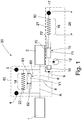
- the Figure 1 shows a torsional vibration damping arrangement 30, which is installed between a drive unit 1 and a gear unit 2.
- the torsional vibration damping arrangement 30 consists primarily of a torsional mass arrangement 40, which is rotatable about the axis of rotation A and a damping arrangement 50, which is not rotatable about the axis of rotation A, but is fixed in position, for example in a trunk of a motor vehicle, not shown here.
- the torsional mass arrangement 40 here consists of a primary inertia element 4 and a secondary inertia element 5, both of which can be rotated relative to one another against the direction of action of a displacement unit 6 and a fixed rigidity 14 connected in parallel therewith.
- the displacer here consists, among other things, of a housing element 60, a displacer piston 62 and a working space with a volume V1.
- the displacement piston 62 is connected to the primary inertia element 4 and the housing element 60 to the secondary inertia element 5. Now rotates the primary inertia element 4 to the secondary inertia element 5, the displacer 62 moves into the working space 61 and displaces an active medium 63 located in the working space 61, which is primarily a fluid, such as hydraulic oil, or a gas, or a combination of hydraulic oil and gas , is executed.
- That displaced Active medium 63 is conducted through a connecting line 8 connected to the working space 61 of the displacement unit 6 to a working space 71 with a volume V2 of a slave cylinder 15 of the damping arrangement 50.
- the connecting line 8 is divided into a rotatable part and a fixed part by a rotary leadthrough 9, since the displacement unit 6 can be rotated about the axis of rotation A, but the slave cylinder 15 is stationary and therefore cannot be rotated about the axis of rotation A.
- the slave cylinder here consists, among other things, of a housing element 70 and a displacer piston 72.
- the displacer piston 72 is connected to an absorber mass 17 by means of a stiffness arrangement 16, which is designed here as an energy store 21 in the form of a steel spring.
- This arrangement of stiffness arrangement 16 and absorber mass can also be referred to as an absorber mass arrangement 28, here in the form of a fixed frequency absorber. If the active medium 63 is now displaced in the working space 61, it reaches the working space 71 of the slave cylinder 15 via the connecting line 8 and displaces the displacement piston 72, which in turn controls the absorber mass arrangement 28.
- This arrangement is particularly advantageous since the actual absorber function is outsourced from the rotating torsional mass arrangement, so that the moment of inertia of the torsional mass arrangement can be kept low, which in turn can have an advantageous effect on a spontaneous response behavior of the drive unit.
- a supply pump 12 for example an oil pressure pump or a compressor, serves for leakage compensation or also for an active superimposition of a periodic pressure curve, which preferably acts in opposite phase.
- a control regulation unit 10 is required which is in operative connection with the active medium 63 and can influence the pressure of the active medium.
- the Figure 2 13 shows a torsional vibration damping arrangement 30 as in FIG Figure 1 shown, but with a load spring 18, which acts on the displacement piston 72 against the direction of action of the active medium 63 in the working space 71 of the slave cylinder 15.
- the load spring 18 can be designed as an elastically deformable element, such as a steel spring, shown here, or as a gas spring, not shown here.
- an additional operating point shift of the effective stiffness arrangement 16 of the absorber mass 17 can be achieved by changing an effective pressure of the active medium 63 against the load spring 18 by the supply pump 12.
- this alternating torque is converted at the displacer unit 6 into an alternating pressure and transmitted to the slave cylinder 15, which in turn comprises the absorber mass arrangement 28, here consisting of the Stiffness arrangement 16 and the damper mass 17 stimulates.
- the absorber mass arrangement 28 acts in opposite phase and thus at least partially extinguishes the vibrations.
- the Figure 3 shows a torsional vibration damping arrangement 30, as in Figure 2 shown, however, with a series connection of the displacer unit 6 and the fixed stiffness 14.
- the series connection of the displacer unit 6 to the fixed stiffness 14 means that the damper mass arrangement 28 has an extinguishing effect on the alternating torque which is introduced via the fixed stiffness 14.
- the supply pump 12, primarily designed as an oil pressure pump, serves to compensate for leaks or to actively overlay a periodic pressure curve, which preferably acts in opposite phases. An operating point shift is also possible here, since the slave cylinder 15 has a load spring element 18.
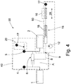
- the Figure 4 shows a torsional vibration damping arrangement 30, as in Figure 3 shown, but only with the displacer 6 between the primary inertia element 4 and the secondary inertia element 5, ie without the fixed rigidity 14, but with an absorber assembly 20 on the secondary inertia element 5, which is designed here as a centrifugal pendulum.
- This embodiment is only to be understood as an example. All known centrifugal pendulums, but also fixed frequency absorbers, consisting of a stiffness and a mass, are possible for this.
- an absorber mass 17 with a stiffness arrangement 16 which is rotatable with respect to the axis of rotation A and is attached to the slave cylinder 15, impresses the stiffness of the load spring element 18 with an opposing pressure curve and at least partially extinguishes the vibrations.
- the control effort of the system is minimal to the main stimulating order or frequency of the drive unit 1, here the internal combustion engine. Due to the low rigidity, a damper mass 29 of the damper assembly can be selected to be smaller since the pre-decoupling by the external spring 18 is very good due to the low rigidity.
Landscapes
- Engineering & Computer Science (AREA)
- General Engineering & Computer Science (AREA)
- Mechanical Engineering (AREA)
- Physics & Mathematics (AREA)
- Acoustics & Sound (AREA)
- Aviation & Aerospace Engineering (AREA)
- Vibration Prevention Devices (AREA)
Description
- Die vorliegende Erfindung betrifft eine Drehschwingungsdämpfungsanordnung für einen Antriebsstrang eines Fahrzeugs, umfassend eine zur Drehung um eine Drehachse anzutreibenden Primärseite und eine über ein Wirkmedium mit der Primärseite zur Drehung um die Drehachse und zur Relativdrehung bezüglich einander gekoppelte Sekundärseite.
- Aus der
DE 10 2006 061 342 A1 ist eine derartige Drehschwingungsdämpfungsanordnung bekannt, bei der eine Primärseite und eine über eine Dämpferfluidanordnung mit der Primärseite zur Drehung um eine Drehachse und zur Relativdrehung bezüglich einander gekoppelte Sekundärseite, wobei die Dämpferfluidanordnung ein ein Drehmoment zwischen der Primärseite und der Sekundärseite übertragendes erstes Dämpferfluid mit geringerer Kompressibilität in einer ersten Dämpferfluidkammeranordnung umfasst sowie ein bei Druckerhöhung des ersten Dämpferfluids in der ersten Dämpferfluidkammeranordnung belastetes zweites Dämpferfluid mit höherer Kompressibilität in einer zweiten Dämpferfluidkammeranordnung umfasst, wobei die zweite Dämpferfluidkammeranordnung eine Mehrzahl vorzugsweise im Wesentlichen zylindrischer Kammereinheiten umfasst, die bezüglich der ersten Dämpferfluidkammeranordnung radial außen oder/und radial innen und in Umfangsrichtung aufeinander folgend angeordnet sind, wobei in Zuordnung zu jeder Kammereinheit ein das erste Dämpferfluid von dem zweiten Dämpferfluid trennendes und bei Druckveränderung in der Kammereinheit im Wesentlichen radial verlagerbares Trennelement vorgesehen ist. Der Vorteil dieses Schwingungsreduzierungssystems ist die weitgehend beliebig niedrig einstellbare Steifigkeit, die eine sehr gute Entkopplung der Drehschwingungen des Verbrennungsmotors ermöglicht. Jedoch ergibt sich der Nachteil, dass in einem unverzweigten Kettenschwinger trotz niedrigster Steifigkeit die Drehschwingungen nicht hinreichend reduziert werden können, da selbst bei einem Absenken nahe 0 eine Seitenwellensteifigkeit des Fahrzeuges, die zum Restantriebsstrang gehört, das Schwingungsverhalten des gesamten Antriebsstrangs definiert. - Es ist die Aufgabe der vorliegenden Erfindung, eine Drehschwingungsdämpfungsanordnung für einen Antriebsstrang eines Fahrzeugs vorzusehen, mit welcher bei kompakter Bauart und geringem Masseträgheitsmoment eine effiziente Minderung von Drehschwingungen in dem in einem Antriebsstrang übertragenen Drehmoment erreicht werden kann.
- Erfindungsgemäß wird diese Aufgabe gelöst durch eine Drehschwingungsdämpfungsanordnung für einen Antriebsstrang eines Fahrzeugs, umfassend eine um eine Drehachse A drehbare Verdrehmassenanordnung und eine außerhalb der Verdrehmassenanordnung angeordnete und mit der Verdrehmassenanordnung wirkverbundene und zur Drehachse A drehfesten Dämpfungsanordnung, wobei die Verdrehmassenanordnung ein um die Drehachse A drehbares Primärträgheitselement und ein zu dem Primärträgheitselement relativ verdrehbares Sekundärträgheitselement und eine Verdrängereinheit umfasst, wobei die Verdrängereinheit einerseits mit dem Primärträgheitselement und andererseits mit dem Sekundärträgheitselement wirkverbunden ist, wobei die Verdrängereinheit einen Arbeitsraum umfasst und wobei durch eine relative Verdrehung des Primärträgheitselements zu dem Sekundärträgheitselement aus einer Ruhelage ein Volumen V1 des Arbeitsraum verändert wird, wobei die Dämpfungsanordnung einen Nehmerzylinder mit einem Arbeitsraum mit einem Volume V2 umfasst und wobei der Arbeitsraum des Nehmerzylinders mit dem Arbeitsraum der Verdrängereinheit wirkverbunden ist, wobei die Dämpfungsanordnung eine Steifigkeitsanordnung und eine Tilgermasse umfasst, wobei der Nehmerzylinder der Dämpfungsanordnung mittels einer Steifigkeitsanordnung mit der Tilgermasse wirkverbunden ist. Durch eine Trennung der Verdrehmassenanordnung, also dem rotierenden System, und der Dämpfungsanordnung, dem drehfesten System, kann die Verdrehmassenanordnung, kompakt und folglich mit einem geringen Massenträgheitsmoment ausgebildet werden, was sich vorteilhaft auf ein spontanes Ansprechverhalten des Antriebsaggregates auswirken kann. Dabei kann die Verdrängereinheit beispielsweise aus einem tangential angeordneten Druckzylinder oder einem Rotationskolbenverdränger, wie einem Flügelzellenverdränger oder einem Zahnradverdränger bestehen. Flügelzellenverdränger haben einen endlichen Verdrehwinkel und Zahnradverdränger einen unendlichen Verdrehwinkel. Dabei ist die Funktion der Drehschwingungsdämpfungsanordnung wie folgt. Von einem Antriebsaggregat, vornehmlich ein Verbrennungsmotor, wird ein Drehmoment mit darin enthaltenen Drehschwingungen an die Primärmassenträgheit weiter geleitet. Bei der Übertragung des Drehmomentes mit den enthaltenen Drehschwingungen an die Sekundärmassenträgheit wandelt die Verdrängereinheit, die vornehmlich aus einem Gehäuseelement, einem Verdrängerkolben und einem Arbeitsraum mit einem Volumen V1 besteht, das Drehmoment in vornehmlich Fluiddruck, wenn als ein Wirkmedium eine Flüssigkeit verwendet wird, um. Über eine Verbindungsleitung und eine Drehdurchführung wird der Fluiddruck von der rotierenden Verdrehmassenanordnung an die drehfeste Dämpfungsanordnung, genauer hier an einen Nehmerzylinder, vornehmlich bestehend aus einem Gehäuseelement, einem Verdrängerkolben und einem Arbeitsraum mit einem Volumen V2 weiter geleitet. Der Nehmerzylinder kann dabei über eine Steifigkeitsanordnung mit einer Tilgermasse verbunden sein. Der Fluiddruck bewirkt nun, dass der Verdrängerkolben mit der Wirkrichtung des Fluiddruckes bewegt wird. Da der Verdrängerkolben wiederum über die Steifigkeitsanordnung mit der Tilgermasse verbunden ist, erfolgt je nach Abstimmung eine gegenphasige Dämpfung der Drehschwingungen und es werden die Drehschwingungen zumindest teilweise ausgelöscht. Weiter kann eine Versorgungspumpe, wie eine Öldruckpumpe und ein Druckspeicher an den Fluiddruck angeschlossen werden um zum einen Leckageausgleich zu tätigen oder auch zum anderen um durch eine Druckänderung eine Lastpunktverstellung und damit eine aktive Überlagerung eines periodischen Druckverlaufes zu erreichen. Hierzu ist eine Steuereinrichtung und eine Regelungseinrichtung erforderlich, die mit dem Fluiddruck in Wirkverbindung zu setzen ist.
- Eine weitere vorteilhafte Ausführungsform sieht vor, dass die Steifigkeitsanordnung der Dämpfungsanordnung einen Energiespeicher umfasst, wobei der Energiespeicher ein elastisch verformbares Element oder ein gaskompressibles Element ist. Dabei kann als elastisch verformbares Element beispielsweise eine Stahlfeder oder als gaskompressibles Element, beispielsweise ein Stickoxidgas als Gasfeder verwendet werden. Dabei ist die Gasfeder vorteilhaft, da ihre Kraft-Weg Kennlinie progressiv ist und über den Weg eine veränderliche Steifigkeit besitzt.
- Eine weitere günstige Ausführungsform sieht vor, dass sich im Arbeitsraum (61) der Verdrängereinheit und im Arbeitsraum des Nehmerzylinders ein Wirkmedium aus einem viskosem Medium oder ein Gas oder eine Kombination aus einem viskosem Medium und einem Gas befindet. Hierbei ist ein viskoses Medium, wie beispielsweise eine Hydraulikflüssigkeit besonders vorteilhaft, da Flüssigkeiten nicht kompressibel sind und sich als Wirkmedium zur Weiterleitung in Form von Druckimpulsen vorteilhaft eignen. Somit können die Wechselmomente vom Antriebsaggregat, die von der Verdrängereinheit als Wechseldrücke umgewandelt werden über das Wirkmedium, hier also eine Hydraulikflüssigkeit, direkt an den Nehmerzylinder weitergeleitet werden können. Da der Nehmerzylinder wiederum in Wirkverbindung mit der Tilgermassenanordnung steht, kann hierdurch eine vorteilhafte Schwingungsreduzierung erzielt werden.
- Eine weitere günstige Ausgestaltung sieht vor, dass die Verdrehmassenanordnung eine feste Steifigkeit mit einem Energiespeicher umfasst, wobei das Primärträgheitselement entgegen der Wirkung des Energiespeichers relativ zu dem Sekundärträgheitselement verdrehbar ist. Dabei kann als Energiespeicher eine Gasfeder oder ein elastisch verformbares Element, wie eine Stahlfeder, eine Kunststofffeder oder ein bekanntes vergleichbares elastisch verformbares Element verwendet werden.
- Dabei kann der Energiespeicher, der zwischen dem Primärträgheitselement und dem Sekundärträgheitselement verbaut ist, parallel oder seriell zu der Verdrängereinheit angeordnet werden.
- Wie bereits vorangehend beschrieben kann als Energiespeicher der Steifigkeitsanordnung, die zwischen dem Primärträgheitselement und dem Sekundärträgheitselement angeordnet ist ein elastisch verformbares Element oder ein gaskompressibles Element verwendet werden.
- Eine weitere Ausführungsform sieht vor, dass der Arbeitsraum der Verdrängereinheit mittels einer Verbindungsleitung mit einem Arbeitsraum 71 des Nehmerzylinders wirkverbunden ist. Dabei ist die Verbindungsleitung so auszuführen, dass diese das Wirkmedium, also die Flüssigkeit, oder das Gas oder eine Kombination aus Flüssigkeit und Gas mit einem geringen Pumpverlust aufnimmt. Dies bedeutet, dass die Wechseldrücke des Wirkmediums nicht eine elastische Verformung der Verbindungsleitung verursachen sollen, was sich nachteilig auf das Ansteuerverhalten der Tilgermassenanordnung auswirken könnte und somit auch nachteilig für die Schwingungsdämpfungs sein kann.
- Eine weitere vorteilhafte Ausgestaltung sieht vor, dass die Verbindungsleitung eine Drehdurchführung umfasst, wobei die Drehdurchführung den um die Drehachse A drehbaren Arbeitsraum der Verdrängereinheit und den zur Drehachse A drehfesten Arbeitsraum des Nehmerzylinders flüssigkeitsdicht und oder gasdicht und zueinander verdrehbar verbindet.
- Weiter kann es vorteilhaft sein, dass die Dämpfungsanordnung eine Versorgungspumpe und oder einen Druckspeicher und oder eine Steuerregelungseinheit umfasst, wobei die Versorgungspumpe und oder der Druckspeicher und oder die Steuerregelungseinheit mit dem Arbeitsraum des Nehmerzylinders wirkverbunden ist. Dies kann zum einen vorteilhaft sein um eine Leckage auszugleichen und oder um eine Lastpunktverschiebung der Tilgermassenanordnung zu erreichen. Hierzu kann der Druck des Wirkmediums durch die Versorgungspumpe und den Druckspeicher verändert werden. Hierzu ist auch Steuerregelungseinheit vorteilhaft, die den notwendigen Druck des Wirkmediums regeln kann. Dabei kann die Versorgungspumpe vorteilhaft eine Öldruckpumpe oder ein Kompressor sein. Die Steuerregelungseinheit umfasst vorteilhaft Sensoren zur Druckerkennung, Druckregelventile und Druckschaltventile.
- Weiter kann der Nehmerzylinder ein Lastfederelement umfassen, wobei das Lastfederelement entgegen einer Wirkungsrichtung einer Volumenänderung V2 des Arbeitsraumes des Nehmerzylinders wirkt. Hierdurch kann eine zusätzlich Betriebspunktverschiebung der wirksamen Tilgersteifigkeit ermöglicht werden, indem der Fluiddruck des Wirkmediums in der Verdrängereinheit und im Nehmerzylinder entgegen der Lastfeder erhöht wird. Diese Lastfeder kann als eine Stahlfeder oder auch als eine Gasfeder ausgeführt sein. Durch das Wechselmoment an dem Verdränger wird über den Wechseldruck auf den Nehmerzylinder die zur Drehachse A drehfeste Tilgermassenanordnung bestehend aus der Tilgermasse und der Tilgersteifigkeitsanordnung angeregt. Bei geeigneter Abstimmung wirkt die Tilgermassenanordnung gegenphasig und löscht so die Schwingungen zumindest teilweise aus.
- In einer weiteren vorteilhaften Ausführungsform umfasst die Verdrehmassenanordnung eine Tilgerbaugruppe, wobei die Tilgerbaugruppe mit dem Primärträgheitselement oder mit dem Sekundärträgheitselement wirkverbunden ist. Dabei kann die Tilgerbaugruppe als Pendel im Fliehkraftfeld ausgeführt sein. Das kann nach dem bekannten Prinzip von Salomon ausgeführt sein. Es kann aber auch ein Massependel nach dem bekannten Prinzip von Sarazin oder jedes funktional geeignete Massependel verwendet werden. Grundsätzlich sind die bekannten Massependel nach dem Prinzip von Salomon oder Sarazin von ihrer funktionsweise gleich. Es kann hier auch von einem Sarazintilger und Salomontilger gesprochen werden. Beide Massependel beruhen auf dem Prinzip der Massenverlagerung gegenüber seinem Trägerteil auf Grund sich verändernder Drehzahlen. Der Salomontilger ist bezüglich des radialen Bauraumbedarfs günstiger. Ein weiterer Vorteil beim Salomontilger ist die einfache Anpassung der Abstimmordnung durch eine entsprechende Auslegung einer Bahngeometrie in der sich das Massependel bewegt. Beim Sarazintilger muss dazu der Schwerpunktradius der Massekörper verändert werden z.B. durch eine federnd gelagerte Masse die mit steigender Drehzahl nach radial außen wandert. Es kann aber auch jede andere Bauart an Fliehkraftpendel, beispielsweise eine Auslenkungsmassenpendeleinheit, bestehend aus einer Auslenkungsmasse und einem elastischen Rückstellelement mit oder ohne variable Einspannlänge, wobei sich diese auch unter Fliehkrafteinwirkung verändern kann, verwendet werden.
- Die vorliegende Erfindung wird nachfolgend mit Bezug auf die beiliegenden Figuren detailliert beschrieben. Es zeigt:
-
Fig. 1 eine Drehschwingungsdämpfungsanordnung mit einer Verdrehmassenanordnung und Dämpfungsanordnung -
Fig. 2 eine Drehschwingungsdämpfungsanordnung wie inFigur 1 , jedoch mit einer Lastfeder im Nehmerzylinder -
Fig. 3 eine Drehschwingungsdämpfungsanordnung wie inFigur 2 , jedoch mit einer Reihenschaltung von Verdrängereinheit und fester Steifigkeit -
Fig. 4 eine Drehschwingungsdämpfungsanordnung wie inFigur 3 , jedoch ohne die feste Steifigkeit, jedoch mit einem Fliehkraftpendel. - Die
Figur 1 zeigt eine Drehschwingungsdämpfungsanordnung 30, die zwischen einem Antriebsaggregat 1 und einem Getriebeaggregat 2 verbaut ist. Dabei besteht hier die Drehschwingungsdämpfungsanordnung 30 vornehmlich aus einer Verdrehmassenanordnung 40, die um die Drehachse A drehbar ist und einer Dämpfungsanordnung 50, die nicht um die Drehachse A drehbar ist, sondern ortsfest, beispielsweise in einem Kofferraum eines Kraftfahrzeuges, hier nicht dargestellt, positioniert ist. Die Verdrehmassenanordnung 40 besteht hier aus einem Primärträgheitselement 4 und einem Sekundärträgheitselement 5, die beide zueinander gegen die Wirkrichtung einer Verdrängereinheit 6 und einer parallel dazu geschalteten festen Steifigkeit 14 verdrehbar sind. Der Verdränger besteht hier unter anderem aus einem Gehäuseelement 60, einem Verdrängerkolben 62 und einem Arbeitsraum mit einem Volumen V1. Dabei ist der Verdrängerkolben 62 mit dem Primärträgheitselement 4 und das Gehäuseelement 60 mit dem Sekundärträgheitselement 5 verbunden. Verdreht sich nun das Primärträgheitselement 4 zu dem Sekundärträgheitselement 5, fährt der Verdrängerkolben 62 in den Arbeitsraum 61 ein und verdrängt ein im Arbeitsraum 61 befindliches Wirkmedium 63, das vornehmlich als ein Fluid, wie Hydrauliköl, oder ein Gas, oder eine Kombination aus Hydrauliköl und Gas, ausgeführt ist. Das verdrängte Wirkmedium 63 wird dabei durch eine mit dem Arbeitsraum 61 der Verdrängereinheit 6 verbundenen Verbindungsleitung 8 zu einem Arbeitsraum 71 mit einem Volumen V2 eines Nehmerzylinder 15 der Dämpfungsanordnung 50 geleitet. Dabei wird die Verbindungsleitung 8 durch eine Drehdurchführung 9 in einen drehbaren Teil und einen feststehenden Teil unterteilt, da die Verdrängereinheit 6 um die Drehachse A drehbar ist, jedoch der Nehmerzylinder 15 ortsfest und damit nicht um die Drehachse A drehbar ist. Der Nehmerzylinder besteht hier unter anderem aus einem Gehäuseelement 70 und einem Verdrängerkolben 72. Dabei ist der Verdrängerkolben 72 mittels einer Steifigkeitsanordnung 16, die hier als Energiespeicher 21 in Form einer Stahlfeder ausgeführt ist, mit einer Tilgermasse 17 verbunden. Diese Anordnung von Steifigkeitsanordnung 16 und Tilgermasse kann auch als eine Tilgermassenanordnung 28, hier in Form eines Festfrequenztilgers, bezeichnet werden. Wird nun im Arbeitsraum 61 das Wirkmedium 63 verdrängt, so gelangt dieses über die Verbindungsleitung 8 in den Arbeitsraum 71 des Nehmerzylinders 15 und verdrängt den Verdrängerkolben 72, der wiederum die Tilgermassenanordnung 28 ansteuert. Diese Anordnung ist besonders vorteilhaft, da die eigentliche Tilgerfunktion aus der rotierenden Verdrehmassenanordnung ausgelagert ist, so dass das Massenträgheitsmoment der Verdrehmassenanordnung gering gehalten werden kann, was sich wiederum vorteilhaft auf ein spontanes Ansprechverhalten des Antriebsaggregates auswirken kann. - Eine Versorgungspumpe 12, beispielsweise eine Öldruckpumpe oder ein Kompressor, dient für einen Leckageausgleich oder auch zu einer aktiven Überlagerung eines periodischen Druckverlaufes, der vorzugsweise gegenphasig wirkt. Hierzu sind jedoch eine Steuerregelungseinheit 10 erforderlich, die mit dem Wirkmedium 63 in Wirkverbindung steht und Einfluss auf den Druck des Wirkmediums nehmen kann.
- Die
Figur 2 zeigt eine Drehschwingungsdämpfungsanordnung 30 wie inFigur 1 gezeigt, jedoch mit einer Lastfeder 18, die auf den Verdrängerkolben 72 entgegen der Wirkrichtung des Wirkmediums 63 im Arbeitsraum 71 des Nehmerzylinders 15 wirkt. Dabei kann die Lastfeder 18 als ein elastisch verformbares Element, wie beispielsweise eine Stahlfeder, hier dargestellt, oder als eine Gasfeder, hier nicht dargestellt, ausgeführt sein. - Hierdurch kann eine zusätzliche Betriebspunktverschiebung der wirksamen Steifigkeitsanordnung 16 der Tilgermasse 17 erreicht werden, indem ein wirksamer Druck des Wirkmediums 63 entgegen der Lastfeder 18 durch die Versorgungspumpe 12 verändert wird. Liegt nun ein Wechselmoment an der Verdrehmassenanordnung 40, hervorgerufen durch das Antriebsaggregat 1, vornehmlich ein Verbrennungsmotor, an, so wird dieses Wechselmoment an der Verdrängereinheit 6 in einen Wechseldruck umgewandelt und auf den Nehmerzylinder 15 übertragen, der wiederum die Tilgermassenanordnung 28, hier bestehend aus der Steifigkeitsanordnung 16 und der Tilgermasse 17 anregt. Bei geeigneter Abstimmung wirkt die Tilgermassenanordnung 28 gegenphasig und löscht so die Schwingungen zumindest teilweise aus.
- Die
Figur 3 zeigt eine Drehschwingungsdämpfungsanordnung 30, wie inFigur 2 gezeigt jedoch mit einer Reihenschaltung von der Verdrängereinheit 6 und der festen Steifigkeit 14. Durch die Reihenschaltung der Verdrängereinheit 6 zu der festen Steifigkeit 14 wirkt die Tilgermassenanordnung 28 aus dem stehenden System auslöschend auf das Wechselmoment, das über die feste Steifigkeit 14 eingeleitet wird. Die Versorgungspumpe 12, vornehmlich hier als eine Öldruckpumpe ausgeführt, dient zum Leckageausgleich oder zur aktiven Überlagerung eines periodischen Druckverlaufes, der vorzugsweise gegenphasig wirkt.
Auch hier eine Betriebspunktverschiebung möglich, da der Nehmerzylinder 15 ein Lastfederelement 18 aufweist. - Die
Figur 4 zeigt eine Drehschwingungsdämpfungsanordnung 30, wie inFigur 3 dargestellt, jedoch nur mit dem Verdränger 6 zwischen dem Primärträgheitselement 4 und dem Sekundärträgheitselement 5, also ohne die feste Steifigkeit 14, jedoch mit einer Tilgerbaugruppe 20 an dem Sekundärträgheitselement 5, die hier als ein Fliehkraftpendel ausgeführt ist. Dabei soll diese Ausführungsform nur beispielhaft verstanden werden. Es sind hierfür alle bekannten Fliehkraftpendel, aber auch Festfrequenztilger, bestehend aus einer Steifigkeit und einer Masse möglich. Auch bei dieser Ausführungsform ist an dem Nehmerzylinder 15 eine zur Drehachse A drehfeste Tilgermasse 17 mit Steifigkeitsanordnung 16 angebracht, der der Steifigkeit des Lastfederelements 18 einen gegenphasigen Druckverlauf aufprägt und die Schwingungen zumindest teilweise auslöscht. Bei einer geeigneter Abstimmung, beispielsweise auf die hauptanregende Ordnung oder Frequenz des Antriebsaggregates 1, hier der Verbrennungsmotors, ist der Regelungsaufwand des Systems minimal. Aufgrund einer niedrigen Steifigkeit kann eine Tilgermasse 29 der Tilgerbaugruppe kleiner gewählt werden, da die Vorentkopplung durch die externe Feder 18 aufgrund der niedrigen Steifigkeit sehr gut ist. -
- 1
- Antriebsaggregat
- 2
- Getriebeaggregat
- 4
- Primärträgheitselement
- 5
- Sekundärträgheitselement
- 6
- Verdrängereinheit
- 8
- Verbindungsleitung
- 9
- Drehdurchführung
- 10
- Steuerregelungseinheit
- 11
- Druckspeicher
- 12
- Versorgungspumpe
- 14
- feste Steifigkeit
- 15
- Nehmerzylinder
- 16
- Steifigkeitsanordnung
- 17
- Tilgermasse
- 18
- Lastfederelement
- 20
- Tilgerbaugruppe
- 21
- Energiespeicher
- 22
- Energiespeicher
- 23
- Energiespeicher
- 24
- Energiespeicher
- 28
- Tilgermassenanordnung
- 29
- Tilgermasse
- 30
- Drehschwingungsdämpfungsanordnung
- 40
- Verdrehmassenanordnung
- 50
- Dämpfungsanordnung
- 60
- Gehäuseelement
- 61
- Arbeitsraum
- 62
- Verdrängerkolben
- 63
- Wirkmedium
- 70
- Gehäuseelement
- 71
- Arbeitsraum
- 72
- Verdrängerkolben
- 81
- Arbeitsraum
- 83
- gaskompressibles Element
- 84
- elastisch verformbares Element
- 90
- Federanordnung
- V1
- Volumen
- V2
- Volumen
- A
- Drehachse
Claims (11)
- Drehschwingungsdämpfungsanordnung (30) für einen Antriebsstrang eines Kraftfahrzeugs, umfassend
eine um eine Drehachse A drehbare Verdrehmassenanordnung (40) und eine außerhalb der Verdrehmassenanordnung (40) angeordnete und mit der Verdrehmassenanordnung (40) wirkverbundene und zur Drehachse A drehfesten Dämpfungsanordnung (50),
wobei die Verdrehmassenanordnung (40) ein um die Drehachse A drehbares Primärträgheitselement (4) und ein zu dem Primärträgheitselement (4) relativ verdrehbares Sekundärträgheitselement (5) und eine Verdrängereinheit (6) umfasst, wobei die Verdrängereinheit (6) einerseits mit dem Primärträgheitselement (4) und andererseits mit dem Sekundärträgheitselement (5) wirkverbunden ist,
wobei die Verdrängereinheit (6) einen Arbeitsraum 61 umfasst und wobei durch eine relative Verdrehung des Primärträgheitselements (4) zu dem Sekundärträgheitselement (5) aus einer Ruhelage ein Volumen V1 des Arbeitsraum (61) verändert wird,
wobei die Dämpfungsanordnung (50) einen Nehmerzylinder (15) mit einem Arbeitsraum (71) mit einem Volume V2 umfasst und wobei der Arbeitsraum (71) des Nehmerzylinders (15) mit dem Arbeitsraum (61) der Verdrängereinheit (6) wirkverbunden ist,
dadurch gekennzeichnet, dass
die Dämpfungsanordnung (50) eine Steifigkeitsanordnung (16) und eine Tilgermasse (17) umfasst, wobei der Nehmerzylinder (15) der Dämpfungsanordnung (50) mittels der Steifigkeitsanordnung (16) mit der Tilgermasse (17) wirkverbunden ist. - Drehschwingungsdämpfungsanordnung (30) nach Anspruch 1, dadurch gekennzeichnet, dass die Steifigkeitsanordnung (16) der Dämpfungsanordnung (50) einen Energiespeicher (21) umfasst, wobei der Energiespeicher (21) ein elastisch verformbares Element oder ein gaskompressibles Element ist.
- Drehschwingungsdämpfungsanordnung (30) nach Anspruch 1 oder 2, dadurch gekennzeichnet, dass sich im Arbeitsraum (61) der Verdrängereinheit (6) und im Arbeitsraum (71) des Nehmerzylinders (15) ein Wirkmedium (63) bestehend aus einem viskoses Medium oder einem Gas oder eine Kombination aus einem viskosem Medium und einem Gas befindet.
- Drehschwingungsdämpfungsanordnung (30) nach einem der vorangehenden Ansprüche, dadurch gekennzeichnet, dass die Verdrehmassenanordnung (40) eine feste Steifigkeit (14) mit einem Energiespeicher (22) umfasst, wobei das Primärträgheitselement (4) entgegen der Wirkung des Energiespeichers (22) relativ zu dem Sekundärträgheitselement (5) verdrehbar ist.
- Drehschwingungsdämpfungsanordnung (30) nach Anspruch 4, dadurch gekennzeichnet, dass der Energiespeicher (22) der Verdrehmassenanordnung (40) parallel oder seriell zu der Verdrängereinheit (6) angeordnet ist.
- Drehschwingungsdämpfungsanordnung (30) nach einem der Ansprüche 4 oder 5, dadurch gekennzeichnet, dass der Energiespeicher der Verdrehmassenanordnung (40) ein elastisch verformbares Element oder ein gaskompressibles Element ist.
- Drehschwingungsdämpfungsanordnung (30) nach einem der vorangehenden Ansprüche, dadurch gekennzeichnet, dass der Arbeitsraum (61) der Verdrängereinheit (6) mittels einer Verbindungsleitung (8) mit einem Arbeitsraum 71 des Nehmerzylinders (15) wirkverbunden ist.
- Drehschwingungsdämpfungsanordnung (30) nach einem der vorangehenden Ansprüche, dadurch gekennzeichnet, dass die Verbindungsleitung (8) eine Drehdurchführung (9) umfasst, wobei die Drehdurchführung (9) den um die Drehachse A drehbaren Arbeitsraum (61) der Verdrängereinheit (6) und den zur Drehachse A drehfesten Arbeitsraum (71) des Nehmerzylinders (15) flüssigkeitsdicht und oder gasdicht und zueinander verdrehbar verbindet.
- Drehschwingungsdämpfungsanordnung (30) nach einem der vorangehenden Ansprüche, dadurch gekennzeichnet, dass die Dämpfungsanordnung (50) eine Versorgungspumpe (12) und oder einen Druckspeicher (11) und / oder eine Steuerregelungseinheit (10) umfasst, umfasst, wobei die Versorgungspumpe (12) und oder der Druckspeicher (11) und / oder die Steuerregelungseinheit (10) mit dem Arbeitsraum (71) des Nehmerzylinders (15) wirkverbunden ist.
- Drehschwingungsdämpfungsanordnung (30) nach einem der vorangehenden Ansprüche, dadurch gekennzeichnet, dass der Nehmerzylinder (15) ein Lastfederelement (18) umfasst, wobei das Lastfederelement (18) entgegen einer Wirkungsrichtung einer Volumenänderung V2 des Arbeitsraumes (71) des Nehmerzylinders (15) wirkt.
- Drehschwingungsdämpfungsanordnung (30) nach einem der vorangehenden Ansprüche, dadurch gekennzeichnet, dass die Verdrehmassenanordnung (40) eine Tilgerbaugruppe (20) umfasst, wobei die Tilgerbaugruppe mit dem Primärträgheitselement (4) oder mit dem Sekundärträgheitselement (5) wirkverbunden ist.
Applications Claiming Priority (2)
| Application Number | Priority Date | Filing Date | Title |
|---|---|---|---|
| DE102016200888.9A DE102016200888A1 (de) | 2016-01-22 | 2016-01-22 | Drehschwingungsdämpfungsanordnung für einen Antriebsstrang eines Fahrzeugs |
| PCT/EP2016/081658 WO2017125221A1 (de) | 2016-01-22 | 2016-12-19 | Drehschwingungsdämpfungsanordnung für einen antriebsstrang eines fahrzeugs |
Publications (2)
| Publication Number | Publication Date |
|---|---|
| EP3405695A1 EP3405695A1 (de) | 2018-11-28 |
| EP3405695B1 true EP3405695B1 (de) | 2020-01-29 |
Family
ID=57614362
Family Applications (1)
| Application Number | Title | Priority Date | Filing Date |
|---|---|---|---|
| EP16819058.5A Active EP3405695B1 (de) | 2016-01-22 | 2016-12-19 | Drehschwingungsdämpfungsanordnung für einen antriebsstrang eines fahrzeugs |
Country Status (7)
| Country | Link |
|---|---|
| US (1) | US10690218B2 (de) |
| EP (1) | EP3405695B1 (de) |
| JP (1) | JP6791971B2 (de) |
| KR (1) | KR20180104689A (de) |
| CN (1) | CN108474437B (de) |
| DE (1) | DE102016200888A1 (de) |
| WO (1) | WO2017125221A1 (de) |
Families Citing this family (3)
| Publication number | Priority date | Publication date | Assignee | Title |
|---|---|---|---|---|
| DE102016200906A1 (de) * | 2016-01-22 | 2017-07-27 | Zf Friedrichshafen Ag | Drehschwingungsdämpfungsanordnung für einen Antriebsstrang eines Fahrzeugs |
| DE102016202178B4 (de) * | 2016-02-12 | 2024-04-25 | Bayerische Motoren Werke Aktiengesellschaft | Vorrichtung zum Reduzieren von Drehschwingungen in einem Antriebsstrang und Verfahren zum Betrieb einer solchen Vorrichtung |
| DE102017125690A1 (de) * | 2017-11-03 | 2019-05-09 | Hasse & Wrede Gmbh | Drehschwingungsdämpfer oder Drehschwingungstilger |
Family Cites Families (17)
| Publication number | Priority date | Publication date | Assignee | Title |
|---|---|---|---|---|
| US4148200A (en) * | 1978-06-05 | 1979-04-10 | General Motors Corporation | Torsional vibration damper for a lock-up clutch |
| JPH04211746A (ja) * | 1990-02-28 | 1992-08-03 | Atsugi Unisia Corp | 自動変速機の動力伝達装置 |
| JPH05202986A (ja) * | 1992-01-28 | 1993-08-10 | Mitsubishi Heavy Ind Ltd | 内燃機関用捩り振動ダンパ給油装置 |
| JPH07224850A (ja) * | 1994-02-10 | 1995-08-22 | Mitsubishi Heavy Ind Ltd | スプリング式弾性軸継手 |
| JP3669226B2 (ja) * | 1999-10-04 | 2005-07-06 | 日産自動車株式会社 | 内燃機関のロール振動低減装置 |
| DE102005018954A1 (de) * | 2005-04-23 | 2006-11-02 | Zf Friedrichshafen Ag | Torsionsschwingungsdämpfer |
| DE102005058531A1 (de) * | 2005-12-08 | 2007-06-14 | Zf Friedrichshafen Ag | Torsionsschwingungsdämpfer |
| DE102006059880A1 (de) * | 2006-12-19 | 2008-06-26 | Zf Friedrichshafen Ag | Torsionssschwingungsdämpferanordnung |
| DE102006061342A1 (de) | 2006-12-22 | 2008-06-26 | Zf Friedrichshafen Ag | Torsionsschwingungsdämpferanordnung |
| DE102007054567A1 (de) * | 2007-11-15 | 2009-05-20 | Zf Friedrichshafen Ag | Torsionsschwingungsdämpferanordnung |
| DE102008002632A1 (de) * | 2007-11-15 | 2009-05-20 | Zf Friedrichshafen Ag | Torsionsschwingungsdämpferanordnung |
| DE102008015817A1 (de) * | 2008-03-27 | 2009-10-01 | Zf Friedrichshafen Ag | Torsionsschwingungsdämpferanordnung, insbesondere für den Antriebsstrang eines Fahrzeugs |
| DE102008017402A1 (de) * | 2008-04-05 | 2009-10-08 | Zf Friedrichshafen Ag | Torsionsschwingungsdämpfer, insbesondere für den Antriebsstrang eines Fahrzeugs |
| DE102008047302A1 (de) * | 2008-09-16 | 2010-04-15 | Zf Friedrichshafen Ag | Torsionsschwingungsdämpferanordnung |
| EP2577105B1 (de) * | 2010-05-25 | 2017-10-25 | ZF Friedrichshafen AG | Hydrodynamische kopplungseinrichtung, insbesondere drehmomentwandler |
| US9068617B2 (en) * | 2013-01-16 | 2015-06-30 | Ford Global Technologies, Llc | Pendulum-absorber brake |
| DE102016200906A1 (de) * | 2016-01-22 | 2017-07-27 | Zf Friedrichshafen Ag | Drehschwingungsdämpfungsanordnung für einen Antriebsstrang eines Fahrzeugs |
-
2016
- 2016-01-22 DE DE102016200888.9A patent/DE102016200888A1/de not_active Withdrawn
- 2016-12-19 JP JP2018538131A patent/JP6791971B2/ja not_active Expired - Fee Related
- 2016-12-19 WO PCT/EP2016/081658 patent/WO2017125221A1/de not_active Ceased
- 2016-12-19 US US16/070,792 patent/US10690218B2/en not_active Expired - Fee Related
- 2016-12-19 CN CN201680079491.0A patent/CN108474437B/zh not_active Expired - Fee Related
- 2016-12-19 EP EP16819058.5A patent/EP3405695B1/de active Active
- 2016-12-19 KR KR1020187024010A patent/KR20180104689A/ko not_active Abandoned
Non-Patent Citations (1)
| Title |
|---|
| None * |
Also Published As
| Publication number | Publication date |
|---|---|
| DE102016200888A1 (de) | 2017-07-27 |
| JP2019507295A (ja) | 2019-03-14 |
| CN108474437A (zh) | 2018-08-31 |
| EP3405695A1 (de) | 2018-11-28 |
| WO2017125221A1 (de) | 2017-07-27 |
| US20190032748A1 (en) | 2019-01-31 |
| JP6791971B2 (ja) | 2020-11-25 |
| KR20180104689A (ko) | 2018-09-21 |
| CN108474437B (zh) | 2020-03-10 |
| US10690218B2 (en) | 2020-06-23 |
Similar Documents
| Publication | Publication Date | Title |
|---|---|---|
| DE112008002980B4 (de) | Drehmomentwandler mit Turbinen-Massentilger | |
| DE3800566C2 (de) | Schwungrad | |
| DE3610127C2 (de) | Drehelastische, schwingungsdämpfende Schwungscheibe | |
| EP1715216B1 (de) | Torsionsschwingungsdämpfer | |
| WO2007065569A1 (de) | Torsionsschwingungsdämpfer | |
| EP2981734A1 (de) | Drehmomentübertragungseinrichtung | |
| WO2008074397A1 (de) | Torsionsschwingungsdämpferanordnung | |
| EP2060824B1 (de) | Torsionsschwingungsdämpferanordnung | |
| EP1953411A2 (de) | Torsionsschwingungsdämpfer | |
| EP3405697B1 (de) | Drehschwingungsdämpfungsanordnung für einen antriebsstrang eines fahrzeugs | |
| EP3405695A1 (de) | Drehschwingungsdämpfungsanordnung für einen antriebsstrang eines fahrzeugs | |
| DE102016202178B4 (de) | Vorrichtung zum Reduzieren von Drehschwingungen in einem Antriebsstrang und Verfahren zum Betrieb einer solchen Vorrichtung | |
| EP1985887B1 (de) | Frequenzabhängiger Schwingungsdämpfer | |
| WO2019086258A1 (de) | Drehschwingungsdämpfer oder drehschwingungstilger | |
| WO2020069933A1 (de) | Elastische kupplung | |
| DE102007026429A1 (de) | Torsionsschwingungsdämpfer | |
| DE102009027219B4 (de) | Torsionsschwingungsdämpferanordnung | |
| DE102005006232B3 (de) | Sperrkupplung mit Steuerung durch magnetorheologisches Fluid | |
| EP0922881B1 (de) | Elastische Kupplung, insbesondere Zweimassenschwungrad für eine Brennkraftmaschine | |
| EP3405696B1 (de) | Drehschwingungsdämpfungsanordnung für einen antriebsstrang eines fahrzeugs | |
| DE19751752A1 (de) | Hydrodynamischer Leistungsüberträger | |
| DE102007034053A1 (de) | Hydrodynamische Kupplungsvorrichtung und Verfahren zu deren Betreiben | |
| EP2146111B1 (de) | Drehelastische Kupplungseinrichtung | |
| EP0446774A1 (de) | Torsionsschwingungsdämpfer | |
| DE102014209570A1 (de) | Drehschwingungsdämpfer |
Legal Events
| Date | Code | Title | Description |
|---|---|---|---|
| STAA | Information on the status of an ep patent application or granted ep patent |
Free format text: STATUS: UNKNOWN |
|
| STAA | Information on the status of an ep patent application or granted ep patent |
Free format text: STATUS: THE INTERNATIONAL PUBLICATION HAS BEEN MADE |
|
| PUAI | Public reference made under article 153(3) epc to a published international application that has entered the european phase |
Free format text: ORIGINAL CODE: 0009012 |
|
| STAA | Information on the status of an ep patent application or granted ep patent |
Free format text: STATUS: REQUEST FOR EXAMINATION WAS MADE |
|
| 17P | Request for examination filed |
Effective date: 20180620 |
|
| AK | Designated contracting states |
Kind code of ref document: A1 Designated state(s): AL AT BE BG CH CY CZ DE DK EE ES FI FR GB GR HR HU IE IS IT LI LT LU LV MC MK MT NL NO PL PT RO RS SE SI SK SM TR |
|
| AX | Request for extension of the european patent |
Extension state: BA ME |
|
| DAV | Request for validation of the european patent (deleted) | ||
| DAX | Request for extension of the european patent (deleted) | ||
| GRAP | Despatch of communication of intention to grant a patent |
Free format text: ORIGINAL CODE: EPIDOSNIGR1 |
|
| STAA | Information on the status of an ep patent application or granted ep patent |
Free format text: STATUS: GRANT OF PATENT IS INTENDED |
|
| INTG | Intention to grant announced |
Effective date: 20190722 |
|
| RIN1 | Information on inventor provided before grant (corrected) |
Inventor name: DIECKHOFF, TOBIAS Inventor name: SIEMENS, KYRILL Inventor name: DOEGEL, THOMAS Inventor name: REISCH, MATTHIAS Inventor name: LORENZ, DANIEL Inventor name: ORLAMUENDER, ANDREAS Inventor name: WACK, ERWIN Inventor name: TERWART, MARKUS Inventor name: ARZNER, MATTHIAS |
|
| GRAS | Grant fee paid |
Free format text: ORIGINAL CODE: EPIDOSNIGR3 |
|
| GRAA | (expected) grant |
Free format text: ORIGINAL CODE: 0009210 |
|
| STAA | Information on the status of an ep patent application or granted ep patent |
Free format text: STATUS: THE PATENT HAS BEEN GRANTED |
|
| AK | Designated contracting states |
Kind code of ref document: B1 Designated state(s): AL AT BE BG CH CY CZ DE DK EE ES FI FR GB GR HR HU IE IS IT LI LT LU LV MC MK MT NL NO PL PT RO RS SE SI SK SM TR |
|
| REG | Reference to a national code |
Ref country code: GB Ref legal event code: FG4D Free format text: NOT ENGLISH |
|
| REG | Reference to a national code |
Ref country code: CH Ref legal event code: EP |
|
| REG | Reference to a national code |
Ref country code: AT Ref legal event code: REF Ref document number: 1228717 Country of ref document: AT Kind code of ref document: T Effective date: 20200215 |
|
| REG | Reference to a national code |
Ref country code: IE Ref legal event code: FG4D Free format text: LANGUAGE OF EP DOCUMENT: GERMAN |
|
| REG | Reference to a national code |
Ref country code: DE Ref legal event code: R096 Ref document number: 502016008588 Country of ref document: DE |
|
| REG | Reference to a national code |
Ref country code: NL Ref legal event code: MP Effective date: 20200129 |
|
| PG25 | Lapsed in a contracting state [announced via postgrant information from national office to epo] |
Ref country code: NO Free format text: LAPSE BECAUSE OF FAILURE TO SUBMIT A TRANSLATION OF THE DESCRIPTION OR TO PAY THE FEE WITHIN THE PRESCRIBED TIME-LIMIT Effective date: 20200429 Ref country code: PT Free format text: LAPSE BECAUSE OF FAILURE TO SUBMIT A TRANSLATION OF THE DESCRIPTION OR TO PAY THE FEE WITHIN THE PRESCRIBED TIME-LIMIT Effective date: 20200621 Ref country code: FI Free format text: LAPSE BECAUSE OF FAILURE TO SUBMIT A TRANSLATION OF THE DESCRIPTION OR TO PAY THE FEE WITHIN THE PRESCRIBED TIME-LIMIT Effective date: 20200129 Ref country code: RS Free format text: LAPSE BECAUSE OF FAILURE TO SUBMIT A TRANSLATION OF THE DESCRIPTION OR TO PAY THE FEE WITHIN THE PRESCRIBED TIME-LIMIT Effective date: 20200129 |
|
| REG | Reference to a national code |
Ref country code: LT Ref legal event code: MG4D |
|
| PG25 | Lapsed in a contracting state [announced via postgrant information from national office to epo] |
Ref country code: LV Free format text: LAPSE BECAUSE OF FAILURE TO SUBMIT A TRANSLATION OF THE DESCRIPTION OR TO PAY THE FEE WITHIN THE PRESCRIBED TIME-LIMIT Effective date: 20200129 Ref country code: IS Free format text: LAPSE BECAUSE OF FAILURE TO SUBMIT A TRANSLATION OF THE DESCRIPTION OR TO PAY THE FEE WITHIN THE PRESCRIBED TIME-LIMIT Effective date: 20200529 Ref country code: SE Free format text: LAPSE BECAUSE OF FAILURE TO SUBMIT A TRANSLATION OF THE DESCRIPTION OR TO PAY THE FEE WITHIN THE PRESCRIBED TIME-LIMIT Effective date: 20200129 Ref country code: HR Free format text: LAPSE BECAUSE OF FAILURE TO SUBMIT A TRANSLATION OF THE DESCRIPTION OR TO PAY THE FEE WITHIN THE PRESCRIBED TIME-LIMIT Effective date: 20200129 Ref country code: BG Free format text: LAPSE BECAUSE OF FAILURE TO SUBMIT A TRANSLATION OF THE DESCRIPTION OR TO PAY THE FEE WITHIN THE PRESCRIBED TIME-LIMIT Effective date: 20200429 Ref country code: GR Free format text: LAPSE BECAUSE OF FAILURE TO SUBMIT A TRANSLATION OF THE DESCRIPTION OR TO PAY THE FEE WITHIN THE PRESCRIBED TIME-LIMIT Effective date: 20200430 |
|
| PG25 | Lapsed in a contracting state [announced via postgrant information from national office to epo] |
Ref country code: NL Free format text: LAPSE BECAUSE OF FAILURE TO SUBMIT A TRANSLATION OF THE DESCRIPTION OR TO PAY THE FEE WITHIN THE PRESCRIBED TIME-LIMIT Effective date: 20200129 |
|
| PG25 | Lapsed in a contracting state [announced via postgrant information from national office to epo] |
Ref country code: LT Free format text: LAPSE BECAUSE OF FAILURE TO SUBMIT A TRANSLATION OF THE DESCRIPTION OR TO PAY THE FEE WITHIN THE PRESCRIBED TIME-LIMIT Effective date: 20200129 Ref country code: CZ Free format text: LAPSE BECAUSE OF FAILURE TO SUBMIT A TRANSLATION OF THE DESCRIPTION OR TO PAY THE FEE WITHIN THE PRESCRIBED TIME-LIMIT Effective date: 20200129 Ref country code: ES Free format text: LAPSE BECAUSE OF FAILURE TO SUBMIT A TRANSLATION OF THE DESCRIPTION OR TO PAY THE FEE WITHIN THE PRESCRIBED TIME-LIMIT Effective date: 20200129 Ref country code: DK Free format text: LAPSE BECAUSE OF FAILURE TO SUBMIT A TRANSLATION OF THE DESCRIPTION OR TO PAY THE FEE WITHIN THE PRESCRIBED TIME-LIMIT Effective date: 20200129 Ref country code: RO Free format text: LAPSE BECAUSE OF FAILURE TO SUBMIT A TRANSLATION OF THE DESCRIPTION OR TO PAY THE FEE WITHIN THE PRESCRIBED TIME-LIMIT Effective date: 20200129 Ref country code: SK Free format text: LAPSE BECAUSE OF FAILURE TO SUBMIT A TRANSLATION OF THE DESCRIPTION OR TO PAY THE FEE WITHIN THE PRESCRIBED TIME-LIMIT Effective date: 20200129 Ref country code: EE Free format text: LAPSE BECAUSE OF FAILURE TO SUBMIT A TRANSLATION OF THE DESCRIPTION OR TO PAY THE FEE WITHIN THE PRESCRIBED TIME-LIMIT Effective date: 20200129 Ref country code: SM Free format text: LAPSE BECAUSE OF FAILURE TO SUBMIT A TRANSLATION OF THE DESCRIPTION OR TO PAY THE FEE WITHIN THE PRESCRIBED TIME-LIMIT Effective date: 20200129 |
|
| REG | Reference to a national code |
Ref country code: DE Ref legal event code: R097 Ref document number: 502016008588 Country of ref document: DE |
|
| PLBE | No opposition filed within time limit |
Free format text: ORIGINAL CODE: 0009261 |
|
| STAA | Information on the status of an ep patent application or granted ep patent |
Free format text: STATUS: NO OPPOSITION FILED WITHIN TIME LIMIT |
|
| 26N | No opposition filed |
Effective date: 20201030 |
|
| PG25 | Lapsed in a contracting state [announced via postgrant information from national office to epo] |
Ref country code: IT Free format text: LAPSE BECAUSE OF FAILURE TO SUBMIT A TRANSLATION OF THE DESCRIPTION OR TO PAY THE FEE WITHIN THE PRESCRIBED TIME-LIMIT Effective date: 20200129 |
|
| PG25 | Lapsed in a contracting state [announced via postgrant information from national office to epo] |
Ref country code: PL Free format text: LAPSE BECAUSE OF FAILURE TO SUBMIT A TRANSLATION OF THE DESCRIPTION OR TO PAY THE FEE WITHIN THE PRESCRIBED TIME-LIMIT Effective date: 20200129 Ref country code: SI Free format text: LAPSE BECAUSE OF FAILURE TO SUBMIT A TRANSLATION OF THE DESCRIPTION OR TO PAY THE FEE WITHIN THE PRESCRIBED TIME-LIMIT Effective date: 20200129 |
|
| REG | Reference to a national code |
Ref country code: CH Ref legal event code: PL |
|
| GBPC | Gb: european patent ceased through non-payment of renewal fee |
Effective date: 20201219 |
|
| PG25 | Lapsed in a contracting state [announced via postgrant information from national office to epo] |
Ref country code: MC Free format text: LAPSE BECAUSE OF FAILURE TO SUBMIT A TRANSLATION OF THE DESCRIPTION OR TO PAY THE FEE WITHIN THE PRESCRIBED TIME-LIMIT Effective date: 20200129 |
|
| REG | Reference to a national code |
Ref country code: BE Ref legal event code: MM Effective date: 20201231 |
|
| PG25 | Lapsed in a contracting state [announced via postgrant information from national office to epo] |
Ref country code: IE Free format text: LAPSE BECAUSE OF NON-PAYMENT OF DUE FEES Effective date: 20201219 Ref country code: LU Free format text: LAPSE BECAUSE OF NON-PAYMENT OF DUE FEES Effective date: 20201219 |
|
| PG25 | Lapsed in a contracting state [announced via postgrant information from national office to epo] |
Ref country code: CH Free format text: LAPSE BECAUSE OF NON-PAYMENT OF DUE FEES Effective date: 20201231 Ref country code: GB Free format text: LAPSE BECAUSE OF NON-PAYMENT OF DUE FEES Effective date: 20201219 Ref country code: LI Free format text: LAPSE BECAUSE OF NON-PAYMENT OF DUE FEES Effective date: 20201231 |
|
| PGFP | Annual fee paid to national office [announced via postgrant information from national office to epo] |
Ref country code: DE Payment date: 20211027 Year of fee payment: 6 |
|
| PG25 | Lapsed in a contracting state [announced via postgrant information from national office to epo] |
Ref country code: TR Free format text: LAPSE BECAUSE OF FAILURE TO SUBMIT A TRANSLATION OF THE DESCRIPTION OR TO PAY THE FEE WITHIN THE PRESCRIBED TIME-LIMIT Effective date: 20200129 Ref country code: MT Free format text: LAPSE BECAUSE OF FAILURE TO SUBMIT A TRANSLATION OF THE DESCRIPTION OR TO PAY THE FEE WITHIN THE PRESCRIBED TIME-LIMIT Effective date: 20200129 Ref country code: CY Free format text: LAPSE BECAUSE OF FAILURE TO SUBMIT A TRANSLATION OF THE DESCRIPTION OR TO PAY THE FEE WITHIN THE PRESCRIBED TIME-LIMIT Effective date: 20200129 |
|
| PG25 | Lapsed in a contracting state [announced via postgrant information from national office to epo] |
Ref country code: MK Free format text: LAPSE BECAUSE OF FAILURE TO SUBMIT A TRANSLATION OF THE DESCRIPTION OR TO PAY THE FEE WITHIN THE PRESCRIBED TIME-LIMIT Effective date: 20200129 Ref country code: AL Free format text: LAPSE BECAUSE OF FAILURE TO SUBMIT A TRANSLATION OF THE DESCRIPTION OR TO PAY THE FEE WITHIN THE PRESCRIBED TIME-LIMIT Effective date: 20200129 |
|
| PG25 | Lapsed in a contracting state [announced via postgrant information from national office to epo] |
Ref country code: BE Free format text: LAPSE BECAUSE OF NON-PAYMENT OF DUE FEES Effective date: 20201231 |
|
| PGFP | Annual fee paid to national office [announced via postgrant information from national office to epo] |
Ref country code: FR Payment date: 20221010 Year of fee payment: 7 |
|
| REG | Reference to a national code |
Ref country code: AT Ref legal event code: MM01 Ref document number: 1228717 Country of ref document: AT Kind code of ref document: T Effective date: 20211219 |
|
| PG25 | Lapsed in a contracting state [announced via postgrant information from national office to epo] |
Ref country code: AT Free format text: LAPSE BECAUSE OF NON-PAYMENT OF DUE FEES Effective date: 20211219 |
|
| REG | Reference to a national code |
Ref country code: DE Ref legal event code: R119 Ref document number: 502016008588 Country of ref document: DE |
|
| P01 | Opt-out of the competence of the unified patent court (upc) registered |
Effective date: 20230528 |
|
| PG25 | Lapsed in a contracting state [announced via postgrant information from national office to epo] |
Ref country code: DE Free format text: LAPSE BECAUSE OF NON-PAYMENT OF DUE FEES Effective date: 20230701 |
|
| PG25 | Lapsed in a contracting state [announced via postgrant information from national office to epo] |
Ref country code: FR Free format text: LAPSE BECAUSE OF NON-PAYMENT OF DUE FEES Effective date: 20231231 |
|
| PG25 | Lapsed in a contracting state [announced via postgrant information from national office to epo] |
Ref country code: FR Free format text: LAPSE BECAUSE OF NON-PAYMENT OF DUE FEES Effective date: 20231231 |