EP3405820B1 - Fibre optique de maintien de polarisation dans un système de réalité virtuelle/augmentée - Google Patents
Fibre optique de maintien de polarisation dans un système de réalité virtuelle/augmentée Download PDFInfo
- Publication number
- EP3405820B1 EP3405820B1 EP17741926.4A EP17741926A EP3405820B1 EP 3405820 B1 EP3405820 B1 EP 3405820B1 EP 17741926 A EP17741926 A EP 17741926A EP 3405820 B1 EP3405820 B1 EP 3405820B1
- Authority
- EP
- European Patent Office
- Prior art keywords
- display
- end user
- display subsystem
- subsystem
- fiber section
- Prior art date
- Legal status (The legal status is an assumption and is not a legal conclusion. Google has not performed a legal analysis and makes no representation as to the accuracy of the status listed.)
- Active
Links
Images


Classifications
-
- G—PHYSICS
- G02—OPTICS
- G02B—OPTICAL ELEMENTS, SYSTEMS OR APPARATUS
- G02B27/00—Optical systems or apparatus not provided for by any of the groups G02B1/00 - G02B26/00, G02B30/00
- G02B27/01—Head-up displays
- G02B27/017—Head mounted
- G02B27/0172—Head mounted characterised by optical features
-
- G—PHYSICS
- G02—OPTICS
- G02B—OPTICAL ELEMENTS, SYSTEMS OR APPARATUS
- G02B26/00—Optical devices or arrangements for the control of light using movable or deformable optical elements
- G02B26/08—Optical devices or arrangements for the control of light using movable or deformable optical elements for controlling the direction of light
- G02B26/10—Scanning systems
- G02B26/103—Scanning systems having movable or deformable optical fibres, light guides or waveguides as scanning elements
-
- G—PHYSICS
- G02—OPTICS
- G02B—OPTICAL ELEMENTS, SYSTEMS OR APPARATUS
- G02B6/00—Light guides; Structural details of arrangements comprising light guides and other optical elements, e.g. couplings
- G02B6/0001—Light guides; Structural details of arrangements comprising light guides and other optical elements, e.g. couplings specially adapted for lighting devices or systems
- G02B6/0005—Light guides; Structural details of arrangements comprising light guides and other optical elements, e.g. couplings specially adapted for lighting devices or systems the light guides being of the fibre type
- G02B6/0008—Light guides; Structural details of arrangements comprising light guides and other optical elements, e.g. couplings specially adapted for lighting devices or systems the light guides being of the fibre type the light being emitted at the end of the fibre
-
- G—PHYSICS
- G02—OPTICS
- G02B—OPTICAL ELEMENTS, SYSTEMS OR APPARATUS
- G02B6/00—Light guides; Structural details of arrangements comprising light guides and other optical elements, e.g. couplings
- G02B6/0001—Light guides; Structural details of arrangements comprising light guides and other optical elements, e.g. couplings specially adapted for lighting devices or systems
- G02B6/0011—Light guides; Structural details of arrangements comprising light guides and other optical elements, e.g. couplings specially adapted for lighting devices or systems the light guides being planar or of plate-like form
-
- G—PHYSICS
- G02—OPTICS
- G02B—OPTICAL ELEMENTS, SYSTEMS OR APPARATUS
- G02B6/00—Light guides; Structural details of arrangements comprising light guides and other optical elements, e.g. couplings
- G02B6/02—Optical fibres with cladding with or without a coating
- G02B6/024—Optical fibres with cladding with or without a coating with polarisation maintaining properties
-
- G—PHYSICS
- G06—COMPUTING OR CALCULATING; COUNTING
- G06T—IMAGE DATA PROCESSING OR GENERATION, IN GENERAL
- G06T19/00—Manipulating three-dimensional [3D] models or images for computer graphics
- G06T19/006—Mixed reality
-
- H—ELECTRICITY
- H04—ELECTRIC COMMUNICATION TECHNIQUE
- H04N—PICTORIAL COMMUNICATION, e.g. TELEVISION
- H04N13/00—Stereoscopic video systems; Multi-view video systems; Details thereof
- H04N13/30—Image reproducers
- H04N13/332—Displays for viewing with the aid of special glasses or head-mounted displays [HMD]
- H04N13/337—Displays for viewing with the aid of special glasses or head-mounted displays [HMD] using polarisation multiplexing
-
- H—ELECTRICITY
- H04—ELECTRIC COMMUNICATION TECHNIQUE
- H04N—PICTORIAL COMMUNICATION, e.g. TELEVISION
- H04N13/00—Stereoscopic video systems; Multi-view video systems; Details thereof
- H04N13/30—Image reproducers
- H04N13/332—Displays for viewing with the aid of special glasses or head-mounted displays [HMD]
- H04N13/344—Displays for viewing with the aid of special glasses or head-mounted displays [HMD] with head-mounted left-right displays
-
- H—ELECTRICITY
- H04—ELECTRIC COMMUNICATION TECHNIQUE
- H04N—PICTORIAL COMMUNICATION, e.g. TELEVISION
- H04N13/00—Stereoscopic video systems; Multi-view video systems; Details thereof
- H04N13/30—Image reproducers
- H04N13/363—Image reproducers using image projection screens
-
- H—ELECTRICITY
- H04—ELECTRIC COMMUNICATION TECHNIQUE
- H04N—PICTORIAL COMMUNICATION, e.g. TELEVISION
- H04N13/00—Stereoscopic video systems; Multi-view video systems; Details thereof
- H04N13/30—Image reproducers
- H04N13/366—Image reproducers using viewer tracking
-
- H—ELECTRICITY
- H04—ELECTRIC COMMUNICATION TECHNIQUE
- H04N—PICTORIAL COMMUNICATION, e.g. TELEVISION
- H04N13/00—Stereoscopic video systems; Multi-view video systems; Details thereof
- H04N13/30—Image reproducers
- H04N13/366—Image reproducers using viewer tracking
- H04N13/383—Image reproducers using viewer tracking for tracking with gaze detection, i.e. detecting the lines of sight of the viewer's eyes
-
- H—ELECTRICITY
- H04—ELECTRIC COMMUNICATION TECHNIQUE
- H04N—PICTORIAL COMMUNICATION, e.g. TELEVISION
- H04N9/00—Details of colour television systems
- H04N9/12—Picture reproducers
- H04N9/31—Projection devices for colour picture display, e.g. using electronic spatial light modulators [ESLM]
- H04N9/3129—Projection devices for colour picture display, e.g. using electronic spatial light modulators [ESLM] scanning a light beam on the display screen
-
- G—PHYSICS
- G02—OPTICS
- G02B—OPTICAL ELEMENTS, SYSTEMS OR APPARATUS
- G02B27/00—Optical systems or apparatus not provided for by any of the groups G02B1/00 - G02B26/00, G02B30/00
- G02B27/01—Head-up displays
- G02B27/017—Head mounted
- G02B2027/0178—Eyeglass type
Definitions
- the present invention generally relates to systems and methods configured to facilitate interactive virtual or augmented reality environments for one or more users.
- a virtual reality (VR) scenario typically involves presentation of digital or virtual image information without transparency to other actual real-world visual input
- AR augmented reality
- a virtual reality (VR) scenario typically involves presentation of digital or virtual image information as an augmentation to visualization of the actual world around the end user.
- an augmented reality scene 4 is depicted wherein a user of an AR technology sees a real-world park-like setting 6 featuring people, trees, buildings in the background, and a concrete platform 8.
- the end user of the AR technology also perceives that he "sees" a robot statue 10 standing upon the real-world platform 8, and a cartoon-like avatar character 12 flying by which seems to be a personification of a bumble bee, even though these elements 10, 12 do not exist in the real world.
- the human visual perception system is very complex, and producing a VR or AR technology that facilitates a comfortable, natural-feeling, rich presentation of virtual image elements amongst other virtual or real-world imagery elements is challenging.
- VR and AR systems typically employ head-worn displays (or helmet-mounted displays, or smart glasses) that are at least loosely coupled to a user's head, and thus move when the end user's head moves. If the end user's head motions are detected by the display subsystem, the data being displayed can be updated to take the change in head pose (i.e., the orientation and/or location of user's head) into account.
- head-worn displays or helmet-mounted displays, or smart glasses
- a user wearing a head-worn display views a virtual representation of a three-dimensional (3D) object on the display and walks around the area where the 3D object appears, that 3D object can be re-rendered for each viewpoint, giving the end user the perception that he or she is walking around an object that occupies real space.
- the head-worn display is used to present multiple objects within a virtual space (for instance, a rich virtual world)
- measurements of head pose can be used to re-render the scene to match the end user's dynamically changing head location and orientation and provide an increased sense of immersion in the virtual space.
- Head-worn displays that enable AR (i.e., the concurrent viewing of real and virtual elements) can have several different types of configurations.
- a video see-through display a camera captures elements of a real scene
- a computing system superimposes virtual elements onto the captured real scene
- a non-transparent display presents the composite image to the eyes.
- Another configuration is often referred to as an "optical see-through” display, in which the end user can see through transparent (or semitransparent) elements in the display subsystem to view directly the light from real objects in the environment.
- the transparent element often referred to as a "combiner,” superimposes light from the display over the end user's view of the real world.
- VR and AR systems typically employ a display subsystem having a projection subsystem and a display surface positioned in front of the end user's field of view and on which the projection subsystem sequentially projects image frames.
- the depth of the display surface can be controlled at frame rates or sub-frame rates.
- the projection subsystem may include one or more optical fibers into which light from one or more light sources emit light of different colors in defined patterns, and a scanning device that scans the optical fiber(s) in a predetermined pattern to create the image frames that sequentially displayed to the end user.
- the display subsystem In a typical head-worn VR/AR system (such as in US 2015/0309264 ), it is desirable to design the display subsystem to be a light-weight as possible to maximize comfort to the user.
- various components of the VR/AR system may be physically contained in a distributed system that includes the display subsystem itself, and a control subsystem locatable remotely from the user's head.
- the control subsystem may be contained in a belt-pack medallion that can be affixed to the waist of the user. Because it is desirable to locate the light source(s) remotely from the head of the user (e.g., in the belt-pack medallion) due to weight, heat, and form factor considerations, the light source(s) must be located with the control subsystem away from the display.
- the optical fiber(s) must be routed from the remote light source(s) to the portion of the display subsystem located on the head of the user.
- a single-mode optical fiber 20 is used for performing both transmission and scanning functions by propagating the light from the remote light source(s) 22 (transmission function) to the scanning device 24, where it is manipulated thereby to scan light in a predetermined scanning pattern (scanning function).
- the polarization of the light injected into the optical fiber(s) from the light source(s) must be maintained through the entirety of the optical fiber(s).
- two polarization modes e.g., vertical and horizontal polarization
- tiny amounts of random birefringence in such a fiber, or bending in the fiber, will cause a tiny amount of crosstalk from the vertical to the horizontal polarization mode.
- the optical fiber(s) may be bent differently (due to user bodily motion, etc.) and thus strained, thereby drastically changing the polarization of the light traveling through the optical fiber(s).
- PM fiber polarization-maintaining optical fiber
- a polarization-maintaining optical fiber which is a single-mode optical fiber in which linearly polarized light, if properly launched into the fiber, maintains a linear polarization during propagation, exiting the fiber in a specific linear polarization state.
- PM fibers maintain linear polarization during propagation by intentionally introducing a systematic linear birefringence in the fiber, so that there are two well-defined polarization modes that propagate along the fiber with very distinct phase velocities.
- Several different PM fiber designs can be used to create birefringence in a fiber.
- the fiber may be geometrically asymmetric or have a refractive index profile that is asymmetric, such as the design using an elliptical cladding, a design using rods of another material within the cladding, or a design using structured-core fibers (e.g., photonic bandgap fibers) to permanently induce stress in the fiber.
- asymmetric such as the design using an elliptical cladding, a design using rods of another material within the cladding, or a design using structured-core fibers (e.g., photonic bandgap fibers) to permanently induce stress in the fiber.
- projection subsystems can be designed with PM fibers in mind
- pre-existing scanning devices are designed to operate with non-PM fibers, which exhibit different mechanical properties than do PM fibers.
- the scanning device will not operate in the same manner when the non-PM fiber(s) are substituted with the polarization maintaining optical fiber(s).
- a PM fiber with highly asymmetrical bending stiffness will have very different dynamics than a non-PM fiber with symmetrical bending stiffness. Consequently, the PM fiber would not achieve a resonant spiral scan, which is the default scanning mode for the display device.
- the distal ends of the optical fiber(s) are typically tapered to increase operating frequency and thus better resolution, thereby resulting in better performance.
- Embodiments of the present invention are directed to devices, systems and methods for facilitating virtual reality and/or augmented reality interaction for one or more users.
- a display subsystem for a virtual image generation system for use by an end user comprises a display (e.g., a planar waveguide apparatus).
- the display may be configured for being positioned in front of the eyes of the end user.
- the display may have a partially transparent display surface configured for being positioned in the field of view between the eyes of the end user and an ambient environment.
- the display subsystem further comprises an optical fiber having a polarization-maintaining (PM) transmission fiber section and a non-PM scanning fiber section.
- the transmission fiber section comprises a cladding having a circularly asymmetrical cross-section.
- the transmission fiber section comprises a circularly symmetrical cladding, and at least one additional element configured for inducing a strain in the cladding.
- the display subsystem further comprises a light source configured for injecting a linearly polarized light beam into the transmission fiber section, such that the linearly polarized light beam is emitted from the scanning fiber section, a mechanical scanning drive assembly in which the scanning fiber section is affixed, wherein the mechanical scanning drive assembly is configured for displacing the scanning optical fiber section is order to scan the emitted light beam, and a display configured for receiving the scanned light beam and generating an image to the end user.
- the proximal end of the scanning fiber section is entirely affixed within the mechanical scanning drive assembly.
- the mechanical scanning drive assembly may comprise a piezoelectric element in which the scanning fiber section is mounted.
- the mechanical scanning drive assembly and the display are integrated into a head-worn unit, and the light source is contained in a remote control unit configured for being worn by end user remotely from the head-worn unit.
- the control unit may be, e.g., worn on the torso or waist of the end user.
- the scanning fiber section may be routed between the remote control unit and the head-worn unit.
- a virtual image generation system for use by an end user, comprises memory storing a three-dimensional scene, a control subsystem (e.g., one comprising a graphics processing unit (GPU)) configured for rendering a plurality of synthetic image frames of the three-dimensional scene, and the display subsystem set forth above.
- the display subsystem is configured for sequentially displaying the plurality of image frames to the end user.
- the virtual image generation system 100 may be operated as an augmented reality subsystem, providing images of virtual objects intermixed with physical objects in a field of view of an end user 50.
- a first approach employs one or more imagers (e.g., cameras) to capture images of the ambient environment.
- the virtual image generation system 100 inter-mixes the virtual images into the data representing the images of the ambient environment.
- a second approach employs one or more at least partially transparent surfaces through which the ambient environment can be seen and on to which the virtual image generation system 100 produces images of virtual objects.
- the virtual image generation system 100 may be employed in applications other than augmented reality and virtual reality subsystems.
- various techniques may be applied to any projection or display subsystem, or may be applied to pico projectors where movement may be made by an end user's hand rather than the head.
- the teachings should not be limited to such subsystems of such uses.
- Virtual objects also referred to herein as virtual tags or tag or call outs, may take any of a large variety of forms, basically any variety of data, information, concept, or logical construct capable of being represented as an image.
- Non-limiting examples of virtual objects may include: a virtual text object, a virtual numeric object, a virtual alphanumeric object, a virtual tag object, a virtual field object, a virtual chart object, a virtual map object, a virtual instrumentation object, or a virtual visual representation of a physical object.
- the virtual image generation system 100 comprises a frame structure 102 worn by an end user 50, a display subsystem 104, at least a portion of which is carried by the frame structure 102, such that the display subsystem 104 is positioned in front of the eyes 52 of the end user 50, and a speaker 106 carried by the frame structure 102, such that the speaker 106 is positioned adjacent the ear canal of the end user 50 (optionally, another speaker (not shown) is positioned adjacent the other ear canal of the end user 50 to provide for stereo/shapeable sound control).
- the display subsystem 104 is designed to present the eyes 52 of the end user 50 with photo-based radiation patterns that can be comfortably perceived as augmentations to physical reality, with high-levels of image quality and three-dimensional perception, as well as being capable of presenting two-dimensional content.
- the display subsystem 104 presents a sequence of synthetic image frames at high frequency that provides the perception of a single coherent scene.
- the display subsystem 104 comprises a projection subsystem 108 and a partially transparent display screen 110 on which the projection subsystem 108 projects images.
- the display screen 110 is positioned in the end user's 50 field of view between the eyes 52 of the end user 50 and an ambient environment.
- the projection subsystem 108 takes the form of an optical fiber scan-based projection device
- the display screen 110 takes the form of a waveguide-based display into which the scanned light from the projection subsystem 108 is injected to produce, e.g., images at single optical viewing distance closer than infinity (e.g., arm's length), images at multiple, discrete optical viewing distances or focal planes, and/or image layers stacked at multiple viewing distances or focal planes to represent volumetric 3D objects.
- These layers in the light field may be stacked closely enough together to appear continuous to the human visual subsystem (i.e., one layer is within the cone of confusion of an adjacent layer).
- picture elements may be blended across two or more layers to increase perceived continuity of transition between layers in the light field, even if those layers are more sparsely stacked (i.e., one layer is outside the cone of confusion of an adjacent layer).
- the display subsystem 104 may be monocular or binocular.
- the projection subsystem 108 includes a scanning assembly 112 that generates and scans a light beam in a predetermined scan pattern in response to control signals, and an optical coupling subsystem 114 that couples the light beam from the scanning assembly 114 into the display screen 110.
- the scanning assembly 112 comprises one or more light sources 116 (only one shown for purposes of simplicity) that produces the light beam (e.g., emits light of different colors in defined patterns).
- the light source 116 may take any of a large variety of forms, for instance, a set of RGB lasers (e.g., laser diodes capable of outputting red, green, and blue light) operable to respectively produce red, green, and blue coherent collimated light according to defined pixel patterns specified in respective frames of pixel information or data.
- RGB lasers e.g., laser diodes capable of outputting red, green, and blue light
- Laser light provides high color saturation and is highly energy efficient.
- the scanning assembly 112 further comprises one or more optical fibers 118 (only one shown for purposes of simplicity), each of which has a proximal end 118a into which a light beam is received from the light source 116 and a distal end 118b from which the light beam is provided to the partially transparent display screen 110.
- the scanning assembly 112 further comprises a mechanical drive assembly 120 to which the optical fiber 118 is mounted.
- the drive assembly 120 is configured for displacing the distal end 118b of the optical fiber 118, and in the illustrated embodiment, comprises a piezoelectric element 122 to which the optical fiber 118 is mounted.
- the scanning assembly 112 further comprises drive electronics 124 configured for conveying electrical signals to the piezoelectric element 122, thereby causing the distal ends 118b of the optical fiber 118 to vibrate in accordance with the scan pattern.
- drive electronics 124 configured for conveying electrical signals to the piezoelectric element 122, thereby causing the distal ends 118b of the optical fiber 118 to vibrate in accordance with the scan pattern.
- the piezoelectric element 122 takes the form of a hollow tube, in which case, the distal end 118b of the optical fiber 118 is threaded or received through the piezoelectric tube 122.
- the distal end 118b of the optical fiber 118 protrudes from the piezoelectric tube 122 as a fixed-free flexible cantilever.
- the piezoelectric tube 122 is associated with four quadrant electrodes (not illustrated).
- the electrodes may, for example, be plated on the outside, outer surface or outer periphery or diameter of the piezoelectric tube 122.
- a core electrode (not illustrated) is also located in a core, center, inner periphery or inner diameter of the tube 122.
- the drive electronics 124 are electrical coupled via wires 126 to drive opposing pairs of electrodes (not shown) to bend the piezoelectric tube 122 in two axes independently.
- the protruding distal end 118b of the optical fiber 118 has mechanical modes of resonance. The frequencies of resonance depend upon a diameter, length, and material properties of the optical fiber 118.
- the piezoelectric tube 122 may be vibrated near a higher order mode (e.g., second order mode) of mechanical resonance, such that the fiber distal end 118b sweeps through smaller deflections about a fulcrum.
- the fiber distal end 118 By stimulating resonant vibration in two axes, the fiber distal end 118 is scanned biaxially in an area filling 2D scan. By modulating an intensity of the light source 116 in synchrony with the scan of the fiber distal end 118b, a light beam emerging from the optical fiber 118 forms an image. Descriptions of such a set up are provided in U.S. Patent Application Ser. No. 13/915,530 , entitled “Multiple Depth Plane Three-Dimensional Display Using A Wave Guide Reflector Array Projector,".
- the optical coupling subsystem 116 includes an optical waveguide input apparatus 128, for instance, one or more reflective surfaces, diffraction gratings, mirrors, dichroic mirrors, or prisms to optically couple light into the end of the display screen 110.
- the optical coupling subsystem 116 further includes a collimation element 130 that collimates light from the optical fiber 118.
- the optical coupling subsystem 116 comprises an optical modulation apparatus (not shown) configured for converging the light from the collimation element 130 towards a focal point in the center of the optical waveguide input apparatus 128, thereby allowing the size of the optical waveguide input apparatus 128 to be minimized, as discussed in further details in U.S. Provisional Patent Application Ser. No. 62/277,865 , entitled "Virtual/Augmented Reality System Having Reverse Angle Diffraction Grating,".
- each of the optical fibers 118 combines the advantages of polarization-maintaining (PM) optical fibers with those of non-PM optical fibers to ensure that the linearly polarization of the light beam propagating through the respective optical fiber 118 is maintained, while maintaining the mechanical properties of the portion of the optical fiber 118 associated with the scanning device 114.
- the optical fiber 118 comprises a non-PM fiber scanning section 132 and a PM transmission fiber section 134.
- Each of the transmission fiber section 132 and the scanning fiber section 134 conventionally includes a transparent core and a transparent cladding material surrounding the core and having a lower index of refraction that keeps light in the core via the phenomenon of total internal reflection, thereby causing the fiber to act as a waveguide.
- the scanning fiber section 132 comprises a transparent core 136 and a cylindrical cladding 138a surrounding the transparent core 136.
- the cladding 138a has a circularly symmetrical refractive index, such that light beam propagates through the scanning fiber section 132 without maintaining the linear polarization of the light beam in the presence of external stresses (see Fig. 7a ).
- the transmission fiber section 134 is similar to the scanning fiber section 132, with the exception that the transmission fiber section 134 comprises a cladding 138b having a geometrically asymmetrical cross-section (e.g., in this case, elliptical) or otherwise has a circularly asymmetrical refractive index to induce birefringence in the fiber, thereby maintaining the linearly polarization of the propagating light beam even in the presence of external stress (see Fig. 7b ).
- the transmission fiber section 134 is similar to the scanning fiber section 132, with the exception that the transmission fiber section 134 further comprises additional elements 140 composed of a different material than the cladding 136a, thereby permanently inducing stress in the fiber (see Fig. 7c ).
- the scanning fiber section 132 is relatively short and is affixed within the scanning device 114, whereas the transmission fiber section 134 is relatively long and is routed from the respective light source 112 to the scanning device 114.
- the transmission fiber section 134 is optically coupled to the respective light source 112, and the scanning fiber section 132 is coupled to the drive assembly 120 of the scanning device 112.
- the scanning fiber section 132 and transmission fiber section 134 are spliced together in any suitable manner that minimizes cladding laser transmission modes.
- the scanning fiber section 132 is affixed within, e.g., the piezoelectric tube 122 of the scanning device 114, stress on the scanning fiber section 132 is prevented, thereby maintaining the linear polarization of the light beam propagating through the scanning fiber section 132.
- linear polarization of the light beam propagating through the transmission fiber section 134 is maintained despite the bending forces applied to the transmission fiber section 134.
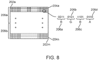
- the display subsystem 104 generates a series of synthetic image frames of pixel information that present an undistorted image of one or more virtual objects to the user.
- a synthetic image frame 200 is schematically illustrated with cells 202a-202m divided into horizontal rows or lines 204a-204n.
- Each cell 202 of the frame 200 may specify values for each of a plurality of colors for the respective pixel to which the cell 202 corresponds and/or intensities.
- the frame 200 may specify one or more values for red 206a, one or more values for green 206b, and one or more values for blue 206c for each pixel.
- the values 206 may be specified as binary representations for each of the colors, for instance, a respective 4-bit number for each color.
- Each cell 202 of the frame 200 may additionally include a value 206d that specifies an amplitude.
- the frame 200 may include one or more fields, collectively 208.
- the frame 200 may consist of a single field.
- the frame 200 may comprise two, or even more fields 208a-208b.
- the pixel information for a complete first field 208a of the frame 200 may be specified before the pixel information for the complete second field 208b, for example occurring before the pixel information for the second field 208b in an array, an ordered list or other data structure (e.g., record, linked list).
- a third or even a fourth field may follow the second field 208b, assuming a presentation subsystem is configured to handle more than two fields 208a-208b.
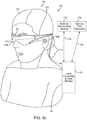
- the virtual image generation system 100 further comprises one or more sensors (not shown) mounted to the frame structure 102 for detecting the position and movement of the head 54 of the end user 50 and/or the eye position and inter-ocular distance of the end user 50.
- sensors may include image capture devices (such as cameras), microphones, inertial measurement units, accelerometers, compasses, GPS units, radio devices, and/or gyros).
- the virtual image generation system 100 comprises a head worn transducer subsystem 142 that includes one or more inertial transducers to capture inertial measures indicative of movement of the head 54 of the end user 50.
- a head worn transducer subsystem 142 that includes one or more inertial transducers to capture inertial measures indicative of movement of the head 54 of the end user 50.
- Such may be used to sense, measure, or collect information about the head movements of the end user 50. For instance, such may be used to detect measurement movements, speeds, acceleration, and/or positions of the head 54 of the end user 50.
- the virtual image generation system 100 further comprises one or more forward facing cameras 144, which may be used to capture information about the environment in which the end user 50 is located.
- the forward facing camera(s) 144 may be used to capture information indicative of distance and orientation of the end user 50 with respect to that environment and specific objects in that environment.
- the forward facing camera(s) 144 is particularly suited to capture information indicative of distance and orientation of the head 54 of the end user 50 with respect to the environment in which the end user 50 is located and specific objects in that environment.
- the forward facing camera(s) 144 may, for example, be employed to detect head movement, speed, and/or acceleration of head movements.
- the forward facing camera(s) 144 may, for example, be employed to detect or infer a center of attention of the end user 50, for example, based at least in part on an orientation of the head 54 of the end user 50. Orientation may be detected in any direction (e.g., up/down, left, right with respect to the reference frame of the end user 50).
- the virtual image generation system 100 further comprises a pair of rearward facing cameras 146 to track movement, blinking, and depth of focus of the eyes 52 of the end user 50.
- eye tracking information may, for example, be discerned by projecting light at the end user's eyes, and detecting the return or reflection of at least some of that projected light.
- Further details discussing eye tracking devices are provided in U.S. Patent Application Ser. No. 14/212,961 , entitled “Display System and Method," U.S. Patent Application Ser. No. 14/726,429 , entitled “Methods and Subsystem for Creating Focal Planes in Virtual and Augmented Reality," and U.S. Patent Application Ser. No. 14/205,126 , entitled “System and Method for Augmented and Virtual Reality,”.
- the virtual image generation system 100 further comprises a user orientation detection module 148.
- the user orientation module 148 detects the instantaneous position of the head 54 of the end user 50 and may predict the position of the head 54 of the end user 50 based on position data received from the sensor(s).
- the user orientation module 148 also tracks the eyes 52 of the end user 50 based on the tracking data received from the sensor(s).
- the virtual image generation system 100 further comprises a control subsystem that may take any of a large variety of forms.
- the control subsystem includes a number of controllers, for instance one or more microcontrollers, microprocessors or central processing units (CPUs), digital signal processors, graphics processing units (GPUs), other integrated circuit controllers, such as application specific integrated circuits (ASICs), programmable gate arrays (PGAs), for instance field PGAs (FPGAs), and/or programmable logic controllers (PLUs).
- controllers for instance one or more microcontrollers, microprocessors or central processing units (CPUs), digital signal processors, graphics processing units (GPUs), other integrated circuit controllers, such as application specific integrated circuits (ASICs), programmable gate arrays (PGAs), for instance field PGAs (FPGAs), and/or programmable logic controllers (PLUs).
- the virtual image generation system 100 comprises a central processing unit (CPU) 150, a graphics processing unit (GPU) 152, and one or more frame buffers 154.
- the CPU 150 controls overall operation, while the GPU 152 renders frames (i.e., translating a three-dimensional scene into a two-dimensional image) and stores these frames in the frame buffer(s) 154.
- one or more additional integrated circuits may control the reading into and/or reading out of frames from the frame buffer(s) 154 and operation of the scanning device of the display subsystem 104. Reading into and/or out of the frame buffer(s) 154 may employ dynamic addressing, for instance, where frames are over-rendered.
- the virtual image generation system 100 further comprises a read only memory (ROM) 156 and a random access memory (RAM) 158.
- the virtual image generation system 100 further comprises a three-dimensional data base 160 from which the GPU 152 can access three-dimensional data of one or more scenes for rendering frames.
- the various processing components of the virtual image generation system 100 may be physically contained in a distributed subsystem.
- the virtual image generation system 100 comprises a local processing and data module 170 operatively coupled, such as by a wired lead or wireless connectivity 172, to a portion of the display subsystem 104 (including the display screen 110 and mechanical drive assembly 120) and sensors.
- the light source(s) 116 and drive electronics 124 are contained in the local processing and data module 170, in which case, the connectivity 172 will include the optical fiber(s) 118.
- the local processing and data module 172 may be mounted in a variety of configurations, such as fixedly attached to the frame structure 102 ( Fig.
- the virtual image generation system 100 further comprises a remote processing module 174 and remote data repository 176 operatively coupled, such as by a wired lead or wireless connectivity 178, 180, to the local processing and data module 170, such that these remote modules 174, 176 are operatively coupled to each other and available as resources to the local processing and data module 170.
- the local processing and data module 170 may comprise a power-efficient processor or controller, as well as digital memory, such as flash memory, both of which may be utilized to assist in the processing, caching, and storage of data captured from the sensors and/or acquired and/or processed using the remote processing module 174 and/or remote data repository 176, possibly for passage to the display subsystem 104 after such processing or retrieval.
- the remote processing module 174 may comprise one or more relatively powerful processors or controllers configured to analyze and process data and/or image information.
- the remote data repository 176 may comprise a relatively large-scale digital data storage facility, which may be available through the internet or other networking configuration in a "cloud" resource configuration. In one embodiment, all data is stored and all computation is performed in the local processing and data module 170, allowing fully autonomous use from any remote modules.
- the couplings 172, 178, 180 between the various components described above may include one or more wired interfaces or ports for providing wires or optical communications, or one or more wireless interfaces or ports, such as via RF, microwave, and IR for providing wireless communications.
- all communications may be wired, while in other implementations all communications may be wireless, with the exception of the optical fiber(s) 118.
- the choice of wired and wireless communications may be different from that illustrated in Figs. 9a-9d . Thus, the particular choice of wired or wireless communications should not be considered limiting.
- the light source(s) 116 and drive electronics 124 of the display subsystem 104 are contained in the local processing and data module 170, in which case, the connectivity 172 will include the optical fiber(s) 118 for connecting these components to the mechanical drive assembly 120 located in close association with the display screen 110).
- the user orientation module 148 is contained in the local processing and data module 170, while the CPU 150 and GPU 152 are contained in the remote processing module 174, although in alternative embodiments, the CPU 150, GPU 152, or portions thereof may be contained in the local processing and data module 170.
- the three dimensional database 160 can be associated with the remote data repository 176.
Landscapes
- Physics & Mathematics (AREA)
- Engineering & Computer Science (AREA)
- Signal Processing (AREA)
- Multimedia (AREA)
- General Physics & Mathematics (AREA)
- Optics & Photonics (AREA)
- Software Systems (AREA)
- General Engineering & Computer Science (AREA)
- Theoretical Computer Science (AREA)
- Computer Hardware Design (AREA)
- Computer Graphics (AREA)
- Mechanical Optical Scanning Systems (AREA)
- Processing Or Creating Images (AREA)
- User Interface Of Digital Computer (AREA)
Claims (15)
- Sous-système d'affichage (104) destiné à un système de génération d'images virtuelles pour son utilisation par un utilisateur final, qui comprend :une fibre optique (118) qui possède une partie faisant office de fibre de balayage (132) non-PM ;une source de lumière (112, 116) ;un assemblage d'entraînement de balayage mécanique (120) dans lequel est fixée la partie de fibre faisant office de fibre de balayage (132) ; dans lequel l'assemblage d'entraînement de balayage mécanique (120) est configuré pour un déplacement de la partie de la fibre optique faisant office de fibre de balayage (132) dans le but de balayer le faisceau de lumière émis ; etun affichage (110) qui est configuré pour la réception du faisceau de lumière balayée et pour la génération d'une image destinée à l'utilisateur final ;caractérisé en ce que la fibre optique possède une partie de fibre faisant office de fibre de transmission qui maintient la polarisation (PM) ; etla source de lumière (112, 116) est configurée pour injecter un faisceau de lumière soumise à une polarisation linéaire dans la partie de fibre faisant office de fibre de transmission (134) d'une manière telle que le faisceau de lumière soumis à une polarisation linéaire est émis à partir de la partie de fibre faisant office de balayage (132).
- Sous-système d'affichage (104) selon la revendication 1, dans lequel l'affichage (110) comprend un appareil faisant office de guide d'onde planaire.
- Sous-système d'affichage (104) selon la revendication 1 ou 2, dans lequel la partie de fibre faisant office de fibre de transmission (134) comprend un gainage (138b) qui possède une section transversale asymétrique de configuration circulaire.
- Sous-système d'affichage (104) selon la revendication 1 ou 2, dans lequel la partie de fibre faisant office de fibre de transmission (134) comprend un gainage symétrique de configuration circulaire (138a), et au moins un élément supplémentaire (140) qui est configuré pour induire une déformation dans le gainage (138a).
- Sous-système d'affichage (104) selon l'une quelconque des revendications 1 à 4, dans lequel l'assemblage d'entraînement de balayage mécanique (120) et l'affichage (110) sont intégrés dans une unité portée sur la tête (102), et la source de lumière (112, 116) est contenue dans une unité de commande à distance (170) qui est configurée pour être portée par l'utilisateur final à distance par rapport à l'unité portée sur la tête (102).
- Sous-système d'affichage (104) selon la revendication 5, dans lequel l'unité de commande (170) est configurée pour être portée sur le torse de l'utilisateur final.
- Sous-système d'affichage (104) selon la revendication 5 ou 6, dans lequel l'unité de commande (170) est configurée pour être portée à la taille de l'utilisateur final.
- Sous-système d'affichage (104) selon l'une quelconque des revendications 5 à 7, dans lequel la partie de fibre faisant office de fibre de balayage (132) est acheminée entre l'unité de commande à distance (170) et l'unité portée sur la tête (102).
- Sous-système d'affichage (104) selon l'une quelconque des revendications 1 à 8, dans lequel une extrémité proximale de la partie de fibre faisant office de fibre de balayage (132) est entièrement fixée au sein de l'assemblage d'entraînement de balayage mécanique (120).
- Sous-système d'affichage (104) selon l'une quelconque des revendications 1 à 9, dans lequel l'assemblage d'entraînement de balayage mécanique (120) comprend un élément piézoélectrique (122) dans lequel est montée la partie de fibre faisant office de fibre de balayage (132).
- Sous-système d'affichage (104) selon l'une quelconque des revendications 1 à 10, dans lequel l'affichage (110) est configuré pour venir se disposer devant les yeux de l'utilisateur final.
- Sous-système d'affichage (104) selon la revendication 11, dans lequel l'affichage (110) possède une surface affichage partiellement transparente qui est configurée pour venir se disposer dans le champ de vision entre les yeux de l'utilisateur final et un environnement ambiant.
- Sous-système d'affichage (104) selon l'une quelconque des revendications 1 à 12, comprenant en outre une structure d'encadrement (102) qui est configurée pour être portée par l'utilisateur final, la structure d'encadrement supportant l'affichage (110) et l'assemblage d'entraînement de balayage mécanique (120).
- Système de génération d'images virtuelles (100) pour son utilisation par un utilisateur final, qui comprend :une mémoire (156, 158) dans laquelle est stockée une scène en trois dimensions ;un sous-système de commande (150, 152, 154) qui est configuré pour la restitution de plusieurs trames d'images de synthèse de la scène en trois dimensions ; etle sous-système d'affichage (104) selon l'une quelconque des revendications 1 à 13, le sous-système d'affichage (104) étant configuré pour afficher de manière séquentielle lesdites plusieurs trames d'images aux yeux de l'utilisateur final.
- Système de génération d'images virtuelles selon la revendication 14, dans lequel le sous-système de commande (150, 152, 154) comprend une unité de traitement d'éléments graphiques (GPU) (152).
Priority Applications (1)
| Application Number | Priority Date | Filing Date | Title |
|---|---|---|---|
| EP21150452.7A EP3825743A1 (fr) | 2016-01-20 | 2017-01-19 | Fibre optique de maintien de polarisation dans un système de réalité virtuelle/augmentée |
Applications Claiming Priority (2)
| Application Number | Priority Date | Filing Date | Title |
|---|---|---|---|
| US201662280992P | 2016-01-20 | 2016-01-20 | |
| PCT/US2017/014138 WO2017127547A1 (fr) | 2016-01-20 | 2017-01-19 | Fibre optique de maintien de polarisation dans un système de réalité virtuelle/augmentée |
Related Child Applications (2)
| Application Number | Title | Priority Date | Filing Date |
|---|---|---|---|
| EP21150452.7A Division-Into EP3825743A1 (fr) | 2016-01-20 | 2017-01-19 | Fibre optique de maintien de polarisation dans un système de réalité virtuelle/augmentée |
| EP21150452.7A Division EP3825743A1 (fr) | 2016-01-20 | 2017-01-19 | Fibre optique de maintien de polarisation dans un système de réalité virtuelle/augmentée |
Publications (3)
| Publication Number | Publication Date |
|---|---|
| EP3405820A1 EP3405820A1 (fr) | 2018-11-28 |
| EP3405820A4 EP3405820A4 (fr) | 2019-01-16 |
| EP3405820B1 true EP3405820B1 (fr) | 2021-02-24 |
Family
ID=59314281
Family Applications (2)
| Application Number | Title | Priority Date | Filing Date |
|---|---|---|---|
| EP17741926.4A Active EP3405820B1 (fr) | 2016-01-20 | 2017-01-19 | Fibre optique de maintien de polarisation dans un système de réalité virtuelle/augmentée |
| EP21150452.7A Ceased EP3825743A1 (fr) | 2016-01-20 | 2017-01-19 | Fibre optique de maintien de polarisation dans un système de réalité virtuelle/augmentée |
Family Applications After (1)
| Application Number | Title | Priority Date | Filing Date |
|---|---|---|---|
| EP21150452.7A Ceased EP3825743A1 (fr) | 2016-01-20 | 2017-01-19 | Fibre optique de maintien de polarisation dans un système de réalité virtuelle/augmentée |
Country Status (9)
| Country | Link |
|---|---|
| US (2) | US10587848B2 (fr) |
| EP (2) | EP3405820B1 (fr) |
| JP (2) | JP6907218B2 (fr) |
| KR (1) | KR102773443B1 (fr) |
| CN (2) | CN113406801B (fr) |
| AU (2) | AU2017209171B2 (fr) |
| CA (1) | CA3009365A1 (fr) |
| IL (2) | IL260064B (fr) |
| WO (1) | WO2017127547A1 (fr) |
Families Citing this family (15)
| Publication number | Priority date | Publication date | Assignee | Title |
|---|---|---|---|---|
| KR102177133B1 (ko) | 2014-01-31 | 2020-11-10 | 매직 립, 인코포레이티드 | 멀티-포컬 디스플레이 시스템 및 방법 |
| WO2017015302A1 (fr) | 2015-07-20 | 2017-01-26 | Magic Leap, Inc. | Conception de scanner à fibre de collimation avec des angles pointant vers l'intérieur dans un système de réalité virtuelle/augmentée |
| AU2016333970B2 (en) | 2015-10-05 | 2021-08-05 | Magic Leap, Inc. | Microlens collimator for scanning optical fiber in virtual/augmented reality system |
| KR102748808B1 (ko) | 2015-10-06 | 2024-12-30 | 매직 립, 인코포레이티드 | 역각 회절 격자를 가진 가상/증강 현실 시스템 |
| AU2017209171B2 (en) | 2016-01-20 | 2021-10-21 | Magic Leap, Inc. | Polarizing maintaining optical fiber in virtual/augmented reality system |
| US10338400B2 (en) | 2017-07-03 | 2019-07-02 | Holovisions LLC | Augmented reality eyewear with VAPE or wear technology |
| US10859834B2 (en) | 2017-07-03 | 2020-12-08 | Holovisions | Space-efficient optical structures for wide field-of-view augmented reality (AR) eyewear |
| CN108803010A (zh) * | 2017-12-07 | 2018-11-13 | 成都理想境界科技有限公司 | 一种提升光纤扫描图像画质的方法及装置 |
| WO2020069371A1 (fr) * | 2018-09-28 | 2020-04-02 | Magic Leap, Inc. | Procédé et système d'un projecteur à balayage à fibre doté d'un oculaire incliné |
| CN114624807B (zh) * | 2018-10-08 | 2024-05-28 | 成都理想境界科技有限公司 | 一种波导模组、基于波导的显示模组及近眼显示设备 |
| KR101982098B1 (ko) * | 2019-02-27 | 2019-05-24 | 주식회사 두리번 | 광섬유 모션 센서 및 이를 포함하는 가상/증강현실 시스템 |
| JP2020144190A (ja) * | 2019-03-05 | 2020-09-10 | 株式会社小糸製作所 | 画像表示装置 |
| US12078813B2 (en) * | 2019-12-13 | 2024-09-03 | Hamamatsu Photonics K.K. | Light source module |
| CN113495360A (zh) * | 2020-03-20 | 2021-10-12 | 宏碁股份有限公司 | 穿戴式显示装置 |
| US12326520B2 (en) * | 2021-03-04 | 2025-06-10 | Beijing Voyager Technology Co., Ltd. | Scanning fiber transmitter for distance detection |
Family Cites Families (102)
| Publication number | Priority date | Publication date | Assignee | Title |
|---|---|---|---|---|
| USRE18452E (en) | 1925-01-02 | 1932-05-03 | Spiral mounted lens disk | |
| US4274854A (en) * | 1978-01-13 | 1981-06-23 | Bell Telephone Laboratories, Incorporated | Polarization-preserving optical fiber |
| NL193330C (nl) * | 1978-01-13 | 1999-06-02 | Western Electric Co | Optische golfleider en werkwijze voor het vervaardigen daarvan. |
| US4472737A (en) | 1982-08-31 | 1984-09-18 | Tokyo Shibaura Denki Kabushiki Kaisha | Stereographic tomogram observing apparatus |
| US4955687A (en) | 1986-07-25 | 1990-09-11 | Pafford Thomas L | Fiber optic telescope |
| KR910002322B1 (ko) | 1986-09-20 | 1991-04-11 | 후지쓰 가부시끼가이샤 | 회절격자렌즈 조립체를 구비하고 있는 광학시스템 |
| US5033814A (en) | 1989-04-10 | 1991-07-23 | Nilford Laboratories, Inc. | Line light source |
| JPH03198022A (ja) | 1989-12-27 | 1991-08-29 | Matsushita Electric Ind Co Ltd | 光ビーム走査装置 |
| JPH05297313A (ja) | 1992-04-17 | 1993-11-12 | Canon Inc | 半導体レーザ偏向素子 |
| JP3252002B2 (ja) | 1993-02-06 | 2002-01-28 | 株式会社堀場製作所 | 多素子型焦電検出器における分岐・集光素子の製造方法 |
| US5764317A (en) | 1995-06-26 | 1998-06-09 | Physical Optics Corporation | 3-D volume visualization display |
| EP0785457A3 (fr) | 1996-01-17 | 1998-10-14 | Nippon Telegraph And Telephone Corporation | Dispositif optique et dispositif d'affichage à trois dimensions |
| US5729242A (en) | 1996-05-08 | 1998-03-17 | Hughes Electronics | Dual PDLC-projection head-up display |
| GB9623682D0 (en) | 1996-11-14 | 1997-01-08 | Philips Electronics Nv | Autostereoscopic display apparatus |
| US6046720A (en) | 1997-05-07 | 2000-04-04 | University Of Washington | Point source scanning apparatus and method |
| US5949941A (en) | 1997-11-21 | 1999-09-07 | Lucent Technologies Inc. | Cladding-pumped fiber structures |
| US6175669B1 (en) * | 1998-03-30 | 2001-01-16 | The Regents Of The Universtiy Of California | Optical coherence domain reflectometry guidewire |
| US6341118B1 (en) | 1998-06-02 | 2002-01-22 | Science Applications International Corporation | Multiple channel scanning device using oversampling and image processing to increase throughput |
| US6504629B1 (en) | 1999-03-23 | 2003-01-07 | Digilens, Inc. | Method and apparatus for illuminating a display |
| US6294775B1 (en) | 1999-06-08 | 2001-09-25 | University Of Washington | Miniature image acquistion system using a scanning resonant waveguide |
| US6525847B2 (en) | 1999-06-16 | 2003-02-25 | Digilens, Inc. | Three dimensional projection systems based on switchable holographic optics |
| US7555333B2 (en) | 2000-06-19 | 2009-06-30 | University Of Washington | Integrated optical scanning image acquisition and display |
| US6845190B1 (en) * | 2000-11-27 | 2005-01-18 | University Of Washington | Control of an optical fiber scanner |
| US6643065B1 (en) | 2001-01-18 | 2003-11-04 | Donn Michael Silberman | Variable spacing diffraction grating |
| US6832012B2 (en) * | 2001-07-06 | 2004-12-14 | Lg Electronics, Inc. | Polarization maintaining optical fiber and projection display of the same |
| JP3918487B2 (ja) | 2001-07-26 | 2007-05-23 | セイコーエプソン株式会社 | 立体表示装置及び投射型立体表示装置 |
| US6702442B2 (en) | 2002-03-08 | 2004-03-09 | Eastman Kodak Company | Monocentric autostereoscopic optical apparatus using resonant fiber-optic image generation |
| IL148804A (en) | 2002-03-21 | 2007-02-11 | Yaacov Amitai | Optical device |
| US7046888B2 (en) | 2002-12-18 | 2006-05-16 | The Regents Of The University Of Michigan | Enhancing fiber-optic sensing technique using a dual-core fiber |
| US7068878B2 (en) | 2003-01-24 | 2006-06-27 | University Of Washington | Optical beam scanning system for compact image display or image acquisition |
| US20040179764A1 (en) | 2003-03-14 | 2004-09-16 | Noureddine Melikechi | Interferometric analog optical modulator for single mode fibers |
| US20040258341A1 (en) * | 2003-06-19 | 2004-12-23 | Paolucci Dora M. | Optical waveguide with radiation-tuned birefringence |
| EP1702103A1 (fr) | 2003-08-18 | 2006-09-20 | Voith Patent GmbH | Procede de raffinage de fibres de papier ou de cellulose en suspension aqueuse |
| US7126693B2 (en) * | 2004-03-29 | 2006-10-24 | Carl Zeiss Meditec, Inc. | Simple high efficiency optical coherence domain reflectometer design |
| US7525541B2 (en) | 2004-04-05 | 2009-04-28 | Actuality Systems, Inc. | Data processing for three-dimensional displays |
| KR20070064319A (ko) | 2004-08-06 | 2007-06-20 | 유니버시티 오브 워싱톤 | 가변 응시 시거리 주사 광 디스플레이 |
| JP4213184B2 (ja) * | 2004-08-12 | 2009-01-21 | 三菱電機株式会社 | 基本波光源及び波長変換器 |
| US8929688B2 (en) | 2004-10-01 | 2015-01-06 | University Of Washington | Remapping methods to reduce distortions in images |
| US7784697B2 (en) | 2004-12-23 | 2010-08-31 | University Of Washington | Methods of driving a scanning beam device to achieve high frame rates |
| EP1834197A1 (fr) | 2004-12-27 | 2007-09-19 | Koninklijke Philips Electronics N.V. | Appareil de correction d'aberration |
| US7189961B2 (en) | 2005-02-23 | 2007-03-13 | University Of Washington | Scanning beam device with detector assembly |
| US7736006B2 (en) | 2005-11-21 | 2010-06-15 | Microvision, Inc. | Substrate-guided display with improved image quality |
| US7953308B2 (en) | 2005-12-30 | 2011-05-31 | General Electric Company | System and method for fiber optic bundle-based illumination for imaging system |
| US20080221388A1 (en) * | 2007-03-09 | 2008-09-11 | University Of Washington | Side viewing optical fiber endoscope |
| US7608842B2 (en) | 2007-04-26 | 2009-10-27 | University Of Washington | Driving scanning fiber devices with variable frequency drive signals |
| JP5228205B2 (ja) * | 2007-06-15 | 2013-07-03 | 独立行政法人情報通信研究機構 | 光波形整形装置 |
| US8437587B2 (en) | 2007-07-25 | 2013-05-07 | University Of Washington | Actuating an optical fiber with a piezoelectric actuator and detecting voltages generated by the piezoelectric actuator |
| JP5169253B2 (ja) | 2008-01-29 | 2013-03-27 | ブラザー工業株式会社 | 画像表示装置 |
| US8757812B2 (en) | 2008-05-19 | 2014-06-24 | University of Washington UW TechTransfer—Invention Licensing | Scanning laser projection display devices and methods for projecting one or more images onto a surface with a light-scanning optical fiber |
| JP2010008948A (ja) | 2008-06-30 | 2010-01-14 | Shinko Electric Ind Co Ltd | 走査型光投影装置 |
| JP5731389B2 (ja) * | 2008-10-22 | 2015-06-10 | コーニンクレッカ フィリップス エヌ ヴェ | 光学的な走査プローブのアセンブリ |
| JP2010152176A (ja) | 2008-12-25 | 2010-07-08 | Mitsubishi Electric Corp | 投写型表示装置 |
| DE102009017940A1 (de) | 2009-04-17 | 2010-10-21 | Storz Endoskop Produktions Gmbh | Endoskopisches System |
| US8184363B2 (en) | 2009-08-07 | 2012-05-22 | Northrop Grumman Systems Corporation | All-fiber integrated high power coherent beam combination |
| US11320571B2 (en) | 2012-11-16 | 2022-05-03 | Rockwell Collins, Inc. | Transparent waveguide display providing upper and lower fields of view with uniform light extraction |
| US9457412B2 (en) | 2009-12-28 | 2016-10-04 | The Board Of Trustees Of The University Of Alabama For And On Behalf Of The University Of Alabama | Fabrication method for diamond film coating of drill bit |
| US8472120B2 (en) | 2010-02-28 | 2013-06-25 | Osterhout Group, Inc. | See-through near-eye display glasses with a small scale image source |
| US8467133B2 (en) | 2010-02-28 | 2013-06-18 | Osterhout Group, Inc. | See-through display with an optical assembly including a wedge-shaped illumination system |
| US8725001B2 (en) | 2010-03-10 | 2014-05-13 | Ofs Fitel, Llc | Multicore fiber transmission systems and methods |
| WO2011123195A1 (fr) * | 2010-03-31 | 2011-10-06 | Sciaky, Inc. | Méthodologie de balayage, et appareil et système pour la fabrication de couches par faisceau d'électrons au moyen d'un système de commande en boucle fermée |
| US8681255B2 (en) | 2010-09-28 | 2014-03-25 | Microsoft Corporation | Integrated low power depth camera and projection device |
| US9292973B2 (en) | 2010-11-08 | 2016-03-22 | Microsoft Technology Licensing, Llc | Automatic variable virtual focus for augmented reality displays |
| US8744782B2 (en) * | 2010-11-16 | 2014-06-03 | Corning Incorporated | System and method for simultaneously determining strain and temperature characteristics of an object |
| FR2971640B1 (fr) * | 2011-02-16 | 2014-04-04 | Univ Bordeaux 1 | Dispositif de pompage optique. |
| US8870381B2 (en) * | 2011-08-10 | 2014-10-28 | Microvision, Inc. | Mixed polarization imaging system for three-dimensional projection and corresponding methods |
| US9373178B2 (en) | 2011-08-24 | 2016-06-21 | Dolby Laboratories Licensing Corporation | High dynamic range displays having wide color gamut and energy efficiency |
| JP5911238B2 (ja) | 2011-09-02 | 2016-04-27 | オリンパス株式会社 | 光走査デバイス及びこれを備えた内視鏡、顕微鏡、プロジェクター |
| US9675252B2 (en) * | 2011-09-27 | 2017-06-13 | British Columbia Cancer Agency Branch | Scanning optical systems |
| KR101524336B1 (ko) | 2011-11-15 | 2015-06-11 | 엘지디스플레이 주식회사 | 박막 평판형 수렴 렌즈 |
| CN102412898B (zh) * | 2011-11-16 | 2014-08-13 | 中国科学院上海光学精密机械研究所 | 无波面畸变自由空间远距离激光传输模拟装置 |
| US8950867B2 (en) | 2011-11-23 | 2015-02-10 | Magic Leap, Inc. | Three dimensional virtual and augmented reality display system |
| EP3798717B1 (fr) | 2012-02-16 | 2023-07-05 | University Of Washington Through Its Center For Commercialization | Profondeur étendue de foyer destinée au balayage d'image à haute résolution |
| US8888275B2 (en) | 2012-05-08 | 2014-11-18 | Microvision, Inc. | Scanned image projection system employing intermediate image plane |
| US9671566B2 (en) * | 2012-06-11 | 2017-06-06 | Magic Leap, Inc. | Planar waveguide apparatus with diffraction element(s) and system employing same |
| WO2013188464A1 (fr) | 2012-06-11 | 2013-12-19 | Magic Leap, Inc. | Affichage tridimensionnel à plans de profondeur multiples utilisant un projecteur à réseau réflecteur de guide d'ondes |
| WO2014005195A2 (fr) | 2012-07-05 | 2014-01-09 | Martin Russell Harris | Appareil et procédé de microscopie à éclairage structuré |
| JP5891131B2 (ja) | 2012-07-11 | 2016-03-22 | 株式会社ソニー・コンピュータエンタテインメント | 画像生成装置および画像生成方法 |
| WO2014015187A1 (fr) | 2012-07-18 | 2014-01-23 | Biological Dynamics, Inc. | Manipulation de microparticules dans des régions diélectrophorétiques de faible champ |
| CN103889301B (zh) | 2012-08-08 | 2016-04-20 | 奥林巴斯株式会社 | 光纤单元 |
| KR20140075163A (ko) | 2012-12-11 | 2014-06-19 | 한국전자통신연구원 | 구조광 방식을 활용한 패턴 프로젝팅 방법 및 장치 |
| JP2014126753A (ja) | 2012-12-27 | 2014-07-07 | Seiko Epson Corp | ヘッドマウントディスプレイ |
| KR102141992B1 (ko) | 2013-01-15 | 2020-08-06 | 매직 립, 인코포레이티드 | 초고해상도 스캐닝 섬유 디스플레이 |
| US8873149B2 (en) | 2013-01-28 | 2014-10-28 | David D. Bohn | Projection optical system for coupling image light to a near-eye display |
| IL308285B2 (en) | 2013-03-11 | 2024-11-01 | Magic Leap Inc | System and method for augmentation and virtual reality |
| WO2014151877A1 (fr) * | 2013-03-14 | 2014-09-25 | The Board Of Trustees Of The Leland Stanford Junior University | Visiocasque holographique |
| US9417452B2 (en) | 2013-03-15 | 2016-08-16 | Magic Leap, Inc. | Display system and method |
| US9874749B2 (en) | 2013-11-27 | 2018-01-23 | Magic Leap, Inc. | Virtual and augmented reality systems and methods |
| WO2015006784A2 (fr) | 2013-07-12 | 2015-01-15 | Magic Leap, Inc. | Appareil à guide d'ondes plan comportant un ou plusieurs éléments de diffraction, et système utilisant cet appareil |
| US9343020B2 (en) | 2013-08-05 | 2016-05-17 | Massachusetts Institute Of Technology | Methods and apparatus for visual display |
| US9763071B2 (en) | 2013-09-22 | 2017-09-12 | Ricoh Company, Ltd. | Mobile information gateway for use in emergency situations or with special equipment |
| US9857591B2 (en) | 2014-05-30 | 2018-01-02 | Magic Leap, Inc. | Methods and system for creating focal planes in virtual and augmented reality |
| CN107272199B (zh) * | 2013-11-27 | 2023-04-07 | 奇跃公司 | 虚拟和增强现实系统与方法 |
| CN106233189B (zh) | 2014-01-31 | 2020-06-26 | 奇跃公司 | 多焦点显示系统和方法 |
| KR102177133B1 (ko) | 2014-01-31 | 2020-11-10 | 매직 립, 인코포레이티드 | 멀티-포컬 디스플레이 시스템 및 방법 |
| JP6270674B2 (ja) * | 2014-02-27 | 2018-01-31 | シチズン時計株式会社 | 投影装置 |
| US10203762B2 (en) | 2014-03-11 | 2019-02-12 | Magic Leap, Inc. | Methods and systems for creating virtual and augmented reality |
| US9389424B1 (en) | 2014-04-02 | 2016-07-12 | Magic Leap, Inc. | Methods and systems for implementing a high resolution color micro-display |
| WO2017015302A1 (fr) | 2015-07-20 | 2017-01-26 | Magic Leap, Inc. | Conception de scanner à fibre de collimation avec des angles pointant vers l'intérieur dans un système de réalité virtuelle/augmentée |
| AU2016333970B2 (en) | 2015-10-05 | 2021-08-05 | Magic Leap, Inc. | Microlens collimator for scanning optical fiber in virtual/augmented reality system |
| KR102748808B1 (ko) | 2015-10-06 | 2024-12-30 | 매직 립, 인코포레이티드 | 역각 회절 격자를 가진 가상/증강 현실 시스템 |
| AU2017209171B2 (en) | 2016-01-20 | 2021-10-21 | Magic Leap, Inc. | Polarizing maintaining optical fiber in virtual/augmented reality system |
| CN109212771A (zh) | 2018-11-27 | 2019-01-15 | 上海天马微电子有限公司 | 一种三维显示装置及显示方法 |
-
2017
- 2017-01-19 AU AU2017209171A patent/AU2017209171B2/en active Active
- 2017-01-19 CA CA3009365A patent/CA3009365A1/fr active Pending
- 2017-01-19 CN CN202110689395.0A patent/CN113406801B/zh active Active
- 2017-01-19 JP JP2018537615A patent/JP6907218B2/ja active Active
- 2017-01-19 KR KR1020187023366A patent/KR102773443B1/ko active Active
- 2017-01-19 CN CN201780007235.5A patent/CN108474904B/zh active Active
- 2017-01-19 US US15/410,456 patent/US10587848B2/en active Active
- 2017-01-19 WO PCT/US2017/014138 patent/WO2017127547A1/fr not_active Ceased
- 2017-01-19 EP EP17741926.4A patent/EP3405820B1/fr active Active
- 2017-01-19 EP EP21150452.7A patent/EP3825743A1/fr not_active Ceased
-
2018
- 2018-06-17 IL IL260064A patent/IL260064B/en active IP Right Grant
-
2020
- 2020-01-08 US US16/737,789 patent/US11317064B2/en active Active
-
2021
- 2021-04-05 IL IL282078A patent/IL282078B/en unknown
- 2021-06-29 JP JP2021107432A patent/JP7121836B2/ja active Active
- 2021-12-23 AU AU2021290337A patent/AU2021290337A1/en not_active Abandoned
Non-Patent Citations (1)
| Title |
|---|
| None * |
Also Published As
| Publication number | Publication date |
|---|---|
| JP7121836B2 (ja) | 2022-08-18 |
| EP3405820A4 (fr) | 2019-01-16 |
| CN113406801B (zh) | 2023-05-30 |
| AU2021290337A1 (en) | 2022-02-03 |
| CN108474904B (zh) | 2021-07-06 |
| KR20180103986A (ko) | 2018-09-19 |
| JP2021165849A (ja) | 2021-10-14 |
| EP3405820A1 (fr) | 2018-11-28 |
| US10587848B2 (en) | 2020-03-10 |
| AU2017209171B2 (en) | 2021-10-21 |
| CA3009365A1 (fr) | 2017-07-27 |
| IL260064B (en) | 2021-04-29 |
| KR102773443B1 (ko) | 2025-02-27 |
| JP2019511734A (ja) | 2019-04-25 |
| CN108474904A (zh) | 2018-08-31 |
| IL260064A (en) | 2018-07-31 |
| AU2017209171A1 (en) | 2018-07-12 |
| US20200145625A1 (en) | 2020-05-07 |
| US11317064B2 (en) | 2022-04-26 |
| IL282078B (en) | 2022-06-01 |
| WO2017127547A1 (fr) | 2017-07-27 |
| EP3825743A1 (fr) | 2021-05-26 |
| US20170208297A1 (en) | 2017-07-20 |
| CN113406801A (zh) | 2021-09-17 |
| IL282078A (en) | 2021-05-31 |
| JP6907218B2 (ja) | 2021-07-21 |
Similar Documents
| Publication | Publication Date | Title |
|---|---|---|
| US11317064B2 (en) | Polarizing maintaining optical fiber in virtual/augmented reality system | |
| US11906739B2 (en) | Microlens collimator for scanning optical fiber in virtual/augmented reality system | |
| US11662585B2 (en) | Virtual/augmented reality system having reverse angle diffraction grating | |
| US10254536B2 (en) | Collimating fiber scanner design with inward pointing angles in virtual/augmented reality system | |
| NZ739170B2 (en) | Collimating fiber scanner design with inward pointing angles in virtual/augmented reality system |
Legal Events
| Date | Code | Title | Description |
|---|---|---|---|
| STAA | Information on the status of an ep patent application or granted ep patent |
Free format text: STATUS: THE INTERNATIONAL PUBLICATION HAS BEEN MADE |
|
| PUAI | Public reference made under article 153(3) epc to a published international application that has entered the european phase |
Free format text: ORIGINAL CODE: 0009012 |
|
| STAA | Information on the status of an ep patent application or granted ep patent |
Free format text: STATUS: REQUEST FOR EXAMINATION WAS MADE |
|
| 17P | Request for examination filed |
Effective date: 20180816 |
|
| AK | Designated contracting states |
Kind code of ref document: A1 Designated state(s): AL AT BE BG CH CY CZ DE DK EE ES FI FR GB GR HR HU IE IS IT LI LT LU LV MC MK MT NL NO PL PT RO RS SE SI SK SM TR |
|
| AX | Request for extension of the european patent |
Extension state: BA ME |
|
| A4 | Supplementary search report drawn up and despatched |
Effective date: 20181219 |
|
| RIC1 | Information provided on ipc code assigned before grant |
Ipc: G02B 26/10 20060101ALI20181213BHEP Ipc: F21V 8/00 20060101ALI20181213BHEP Ipc: G02B 6/024 20060101AFI20181213BHEP Ipc: H04N 13/337 20180101ALI20181213BHEP Ipc: G02B 27/01 20060101ALI20181213BHEP Ipc: G06T 19/00 20110101ALI20181213BHEP |
|
| DAV | Request for validation of the european patent (deleted) | ||
| DAX | Request for extension of the european patent (deleted) | ||
| GRAP | Despatch of communication of intention to grant a patent |
Free format text: ORIGINAL CODE: EPIDOSNIGR1 |
|
| STAA | Information on the status of an ep patent application or granted ep patent |
Free format text: STATUS: GRANT OF PATENT IS INTENDED |
|
| RIC1 | Information provided on ipc code assigned before grant |
Ipc: G06T 19/00 20110101ALI20200727BHEP Ipc: G02B 27/01 20060101ALI20200727BHEP Ipc: G02B 6/024 20060101AFI20200727BHEP Ipc: G02B 26/10 20060101ALI20200727BHEP Ipc: H04N 13/337 20180101ALI20200727BHEP Ipc: F21V 8/00 20060101ALI20200727BHEP |
|
| INTG | Intention to grant announced |
Effective date: 20200826 |
|
| RIN1 | Information on inventor provided before grant (corrected) |
Inventor name: YEOH, IVAN Inventor name: EDWIN, LIONEL ERNEST Inventor name: TINCH, DAVID |
|
| GRAS | Grant fee paid |
Free format text: ORIGINAL CODE: EPIDOSNIGR3 |
|
| GRAA | (expected) grant |
Free format text: ORIGINAL CODE: 0009210 |
|
| STAA | Information on the status of an ep patent application or granted ep patent |
Free format text: STATUS: THE PATENT HAS BEEN GRANTED |
|
| AK | Designated contracting states |
Kind code of ref document: B1 Designated state(s): AL AT BE BG CH CY CZ DE DK EE ES FI FR GB GR HR HU IE IS IT LI LT LU LV MC MK MT NL NO PL PT RO RS SE SI SK SM TR |
|
| REG | Reference to a national code |
Ref country code: CH Ref legal event code: EP |
|
| REG | Reference to a national code |
Ref country code: AT Ref legal event code: REF Ref document number: 1365204 Country of ref document: AT Kind code of ref document: T Effective date: 20210315 |
|
| REG | Reference to a national code |
Ref country code: IE Ref legal event code: FG4D |
|
| REG | Reference to a national code |
Ref country code: DE Ref legal event code: R096 Ref document number: 602017033289 Country of ref document: DE |
|
| REG | Reference to a national code |
Ref country code: NL Ref legal event code: FP |
|
| REG | Reference to a national code |
Ref country code: LT Ref legal event code: MG9D |
|
| PG25 | Lapsed in a contracting state [announced via postgrant information from national office to epo] |
Ref country code: LT Free format text: LAPSE BECAUSE OF FAILURE TO SUBMIT A TRANSLATION OF THE DESCRIPTION OR TO PAY THE FEE WITHIN THE PRESCRIBED TIME-LIMIT Effective date: 20210224 Ref country code: BG Free format text: LAPSE BECAUSE OF FAILURE TO SUBMIT A TRANSLATION OF THE DESCRIPTION OR TO PAY THE FEE WITHIN THE PRESCRIBED TIME-LIMIT Effective date: 20210524 Ref country code: HR Free format text: LAPSE BECAUSE OF FAILURE TO SUBMIT A TRANSLATION OF THE DESCRIPTION OR TO PAY THE FEE WITHIN THE PRESCRIBED TIME-LIMIT Effective date: 20210224 Ref country code: GR Free format text: LAPSE BECAUSE OF FAILURE TO SUBMIT A TRANSLATION OF THE DESCRIPTION OR TO PAY THE FEE WITHIN THE PRESCRIBED TIME-LIMIT Effective date: 20210525 Ref country code: FI Free format text: LAPSE BECAUSE OF FAILURE TO SUBMIT A TRANSLATION OF THE DESCRIPTION OR TO PAY THE FEE WITHIN THE PRESCRIBED TIME-LIMIT Effective date: 20210224 Ref country code: PT Free format text: LAPSE BECAUSE OF FAILURE TO SUBMIT A TRANSLATION OF THE DESCRIPTION OR TO PAY THE FEE WITHIN THE PRESCRIBED TIME-LIMIT Effective date: 20210624 Ref country code: NO Free format text: LAPSE BECAUSE OF FAILURE TO SUBMIT A TRANSLATION OF THE DESCRIPTION OR TO PAY THE FEE WITHIN THE PRESCRIBED TIME-LIMIT Effective date: 20210524 |
|
| REG | Reference to a national code |
Ref country code: AT Ref legal event code: MK05 Ref document number: 1365204 Country of ref document: AT Kind code of ref document: T Effective date: 20210224 |
|
| PG25 | Lapsed in a contracting state [announced via postgrant information from national office to epo] |
Ref country code: PL Free format text: LAPSE BECAUSE OF FAILURE TO SUBMIT A TRANSLATION OF THE DESCRIPTION OR TO PAY THE FEE WITHIN THE PRESCRIBED TIME-LIMIT Effective date: 20210224 Ref country code: LV Free format text: LAPSE BECAUSE OF FAILURE TO SUBMIT A TRANSLATION OF THE DESCRIPTION OR TO PAY THE FEE WITHIN THE PRESCRIBED TIME-LIMIT Effective date: 20210224 Ref country code: RS Free format text: LAPSE BECAUSE OF FAILURE TO SUBMIT A TRANSLATION OF THE DESCRIPTION OR TO PAY THE FEE WITHIN THE PRESCRIBED TIME-LIMIT Effective date: 20210224 Ref country code: SE Free format text: LAPSE BECAUSE OF FAILURE TO SUBMIT A TRANSLATION OF THE DESCRIPTION OR TO PAY THE FEE WITHIN THE PRESCRIBED TIME-LIMIT Effective date: 20210224 |
|
| PG25 | Lapsed in a contracting state [announced via postgrant information from national office to epo] |
Ref country code: IS Free format text: LAPSE BECAUSE OF FAILURE TO SUBMIT A TRANSLATION OF THE DESCRIPTION OR TO PAY THE FEE WITHIN THE PRESCRIBED TIME-LIMIT Effective date: 20210624 |
|
| PG25 | Lapsed in a contracting state [announced via postgrant information from national office to epo] |
Ref country code: SM Free format text: LAPSE BECAUSE OF FAILURE TO SUBMIT A TRANSLATION OF THE DESCRIPTION OR TO PAY THE FEE WITHIN THE PRESCRIBED TIME-LIMIT Effective date: 20210224 Ref country code: AT Free format text: LAPSE BECAUSE OF FAILURE TO SUBMIT A TRANSLATION OF THE DESCRIPTION OR TO PAY THE FEE WITHIN THE PRESCRIBED TIME-LIMIT Effective date: 20210224 Ref country code: EE Free format text: LAPSE BECAUSE OF FAILURE TO SUBMIT A TRANSLATION OF THE DESCRIPTION OR TO PAY THE FEE WITHIN THE PRESCRIBED TIME-LIMIT Effective date: 20210224 Ref country code: CZ Free format text: LAPSE BECAUSE OF FAILURE TO SUBMIT A TRANSLATION OF THE DESCRIPTION OR TO PAY THE FEE WITHIN THE PRESCRIBED TIME-LIMIT Effective date: 20210224 |
|
| REG | Reference to a national code |
Ref country code: DE Ref legal event code: R097 Ref document number: 602017033289 Country of ref document: DE |
|
| PG25 | Lapsed in a contracting state [announced via postgrant information from national office to epo] |
Ref country code: RO Free format text: LAPSE BECAUSE OF FAILURE TO SUBMIT A TRANSLATION OF THE DESCRIPTION OR TO PAY THE FEE WITHIN THE PRESCRIBED TIME-LIMIT Effective date: 20210224 Ref country code: DK Free format text: LAPSE BECAUSE OF FAILURE TO SUBMIT A TRANSLATION OF THE DESCRIPTION OR TO PAY THE FEE WITHIN THE PRESCRIBED TIME-LIMIT Effective date: 20210224 Ref country code: SK Free format text: LAPSE BECAUSE OF FAILURE TO SUBMIT A TRANSLATION OF THE DESCRIPTION OR TO PAY THE FEE WITHIN THE PRESCRIBED TIME-LIMIT Effective date: 20210224 |
|
| PLBE | No opposition filed within time limit |
Free format text: ORIGINAL CODE: 0009261 |
|
| STAA | Information on the status of an ep patent application or granted ep patent |
Free format text: STATUS: NO OPPOSITION FILED WITHIN TIME LIMIT |
|
| PG25 | Lapsed in a contracting state [announced via postgrant information from national office to epo] |
Ref country code: ES Free format text: LAPSE BECAUSE OF FAILURE TO SUBMIT A TRANSLATION OF THE DESCRIPTION OR TO PAY THE FEE WITHIN THE PRESCRIBED TIME-LIMIT Effective date: 20210224 Ref country code: AL Free format text: LAPSE BECAUSE OF FAILURE TO SUBMIT A TRANSLATION OF THE DESCRIPTION OR TO PAY THE FEE WITHIN THE PRESCRIBED TIME-LIMIT Effective date: 20210224 |
|
| 26N | No opposition filed |
Effective date: 20211125 |
|
| PG25 | Lapsed in a contracting state [announced via postgrant information from national office to epo] |
Ref country code: SI Free format text: LAPSE BECAUSE OF FAILURE TO SUBMIT A TRANSLATION OF THE DESCRIPTION OR TO PAY THE FEE WITHIN THE PRESCRIBED TIME-LIMIT Effective date: 20210224 |
|
| PG25 | Lapsed in a contracting state [announced via postgrant information from national office to epo] |
Ref country code: IT Free format text: LAPSE BECAUSE OF FAILURE TO SUBMIT A TRANSLATION OF THE DESCRIPTION OR TO PAY THE FEE WITHIN THE PRESCRIBED TIME-LIMIT Effective date: 20210224 |
|
| PG25 | Lapsed in a contracting state [announced via postgrant information from national office to epo] |
Ref country code: IS Free format text: LAPSE BECAUSE OF FAILURE TO SUBMIT A TRANSLATION OF THE DESCRIPTION OR TO PAY THE FEE WITHIN THE PRESCRIBED TIME-LIMIT Effective date: 20210624 |
|
| PG25 | Lapsed in a contracting state [announced via postgrant information from national office to epo] |
Ref country code: MC Free format text: LAPSE BECAUSE OF FAILURE TO SUBMIT A TRANSLATION OF THE DESCRIPTION OR TO PAY THE FEE WITHIN THE PRESCRIBED TIME-LIMIT Effective date: 20210224 |
|
| REG | Reference to a national code |
Ref country code: CH Ref legal event code: PL |
|
| PG25 | Lapsed in a contracting state [announced via postgrant information from national office to epo] |
Ref country code: LU Free format text: LAPSE BECAUSE OF NON-PAYMENT OF DUE FEES Effective date: 20220119 |
|
| PG25 | Lapsed in a contracting state [announced via postgrant information from national office to epo] |
Ref country code: LI Free format text: LAPSE BECAUSE OF NON-PAYMENT OF DUE FEES Effective date: 20220131 Ref country code: CH Free format text: LAPSE BECAUSE OF NON-PAYMENT OF DUE FEES Effective date: 20220131 |
|
| PG25 | Lapsed in a contracting state [announced via postgrant information from national office to epo] |
Ref country code: IE Free format text: LAPSE BECAUSE OF NON-PAYMENT OF DUE FEES Effective date: 20220119 |
|
| P01 | Opt-out of the competence of the unified patent court (upc) registered |
Effective date: 20230607 |
|
| PG25 | Lapsed in a contracting state [announced via postgrant information from national office to epo] |
Ref country code: HU Free format text: LAPSE BECAUSE OF FAILURE TO SUBMIT A TRANSLATION OF THE DESCRIPTION OR TO PAY THE FEE WITHIN THE PRESCRIBED TIME-LIMIT; INVALID AB INITIO Effective date: 20170119 |
|
| PG25 | Lapsed in a contracting state [announced via postgrant information from national office to epo] |
Ref country code: MK Free format text: LAPSE BECAUSE OF FAILURE TO SUBMIT A TRANSLATION OF THE DESCRIPTION OR TO PAY THE FEE WITHIN THE PRESCRIBED TIME-LIMIT Effective date: 20210224 Ref country code: CY Free format text: LAPSE BECAUSE OF FAILURE TO SUBMIT A TRANSLATION OF THE DESCRIPTION OR TO PAY THE FEE WITHIN THE PRESCRIBED TIME-LIMIT Effective date: 20210224 |
|
| PG25 | Lapsed in a contracting state [announced via postgrant information from national office to epo] |
Ref country code: TR Free format text: LAPSE BECAUSE OF FAILURE TO SUBMIT A TRANSLATION OF THE DESCRIPTION OR TO PAY THE FEE WITHIN THE PRESCRIBED TIME-LIMIT Effective date: 20210224 |
|
| PG25 | Lapsed in a contracting state [announced via postgrant information from national office to epo] |
Ref country code: MT Free format text: LAPSE BECAUSE OF FAILURE TO SUBMIT A TRANSLATION OF THE DESCRIPTION OR TO PAY THE FEE WITHIN THE PRESCRIBED TIME-LIMIT Effective date: 20210224 |
|
| PGFP | Annual fee paid to national office [announced via postgrant information from national office to epo] |
Ref country code: GB Payment date: 20251220 Year of fee payment: 10 |
|
| PGFP | Annual fee paid to national office [announced via postgrant information from national office to epo] |
Ref country code: NL Payment date: 20251217 Year of fee payment: 10 Ref country code: FR Payment date: 20251217 Year of fee payment: 10 |
|
| PGFP | Annual fee paid to national office [announced via postgrant information from national office to epo] |
Ref country code: BE Payment date: 20251217 Year of fee payment: 10 |
|
| PGFP | Annual fee paid to national office [announced via postgrant information from national office to epo] |
Ref country code: DE Payment date: 20251217 Year of fee payment: 10 |