EP3406024B1 - Procédé et appareil pour réaliser une commande à sécurité intégrée et à économies d'énergie électrique d'un frein électromécanique - Google Patents
Procédé et appareil pour réaliser une commande à sécurité intégrée et à économies d'énergie électrique d'un frein électromécanique Download PDFInfo
- Publication number
- EP3406024B1 EP3406024B1 EP17704126.6A EP17704126A EP3406024B1 EP 3406024 B1 EP3406024 B1 EP 3406024B1 EP 17704126 A EP17704126 A EP 17704126A EP 3406024 B1 EP3406024 B1 EP 3406024B1
- Authority
- EP
- European Patent Office
- Prior art keywords
- brake
- switching regulator
- switch
- control circuit
- control
- Prior art date
- Legal status (The legal status is an assumption and is not a legal conclusion. Google has not performed a legal analysis and makes no representation as to the accuracy of the status listed.)
- Active
Links
Images



Classifications
-
- F—MECHANICAL ENGINEERING; LIGHTING; HEATING; WEAPONS; BLASTING
- F16—ENGINEERING ELEMENTS AND UNITS; GENERAL MEASURES FOR PRODUCING AND MAINTAINING EFFECTIVE FUNCTIONING OF MACHINES OR INSTALLATIONS; THERMAL INSULATION IN GENERAL
- F16D—COUPLINGS FOR TRANSMITTING ROTATION; CLUTCHES; BRAKES
- F16D63/00—Brakes not otherwise provided for; Brakes combining more than one of the types of groups F16D49/00 - F16D61/00
- F16D63/002—Brakes with direct electrical or electro-magnetic actuation
-
- H—ELECTRICITY
- H02—GENERATION; CONVERSION OR DISTRIBUTION OF ELECTRIC POWER
- H02P—CONTROL OR REGULATION OF ELECTRIC MOTORS, ELECTRIC GENERATORS OR DYNAMO-ELECTRIC CONVERTERS; CONTROLLING TRANSFORMERS, REACTORS OR CHOKE COILS
- H02P29/00—Arrangements for regulating or controlling electric motors, appropriate for both AC and DC motors
- H02P29/04—Arrangements for regulating or controlling electric motors, appropriate for both AC and DC motors by means of a separate brake
-
- H—ELECTRICITY
- H01—ELECTRIC ELEMENTS
- H01F—MAGNETS; INDUCTANCES; TRANSFORMERS; SELECTION OF MATERIALS FOR THEIR MAGNETIC PROPERTIES
- H01F7/00—Magnets
- H01F7/06—Electromagnets; Actuators including electromagnets
- H01F7/064—Circuit arrangements for actuating electromagnets
-
- H—ELECTRICITY
- H02—GENERATION; CONVERSION OR DISTRIBUTION OF ELECTRIC POWER
- H02P—CONTROL OR REGULATION OF ELECTRIC MOTORS, ELECTRIC GENERATORS OR DYNAMO-ELECTRIC CONVERTERS; CONTROLLING TRANSFORMERS, REACTORS OR CHOKE COILS
- H02P3/00—Arrangements for stopping or slowing electric motors, generators, or dynamo-electric converters
- H02P3/02—Details of stopping control
- H02P3/04—Means for stopping or slowing by a separate brake, e.g. friction brake or eddy-current brake
-
- F—MECHANICAL ENGINEERING; LIGHTING; HEATING; WEAPONS; BLASTING
- F16—ENGINEERING ELEMENTS AND UNITS; GENERAL MEASURES FOR PRODUCING AND MAINTAINING EFFECTIVE FUNCTIONING OF MACHINES OR INSTALLATIONS; THERMAL INSULATION IN GENERAL
- F16D—COUPLINGS FOR TRANSMITTING ROTATION; CLUTCHES; BRAKES
- F16D2121/00—Type of actuator operation force
- F16D2121/18—Electric or magnetic
- F16D2121/20—Electric or magnetic using electromagnets
Definitions
- This invention is directed toward braking systems for an electric motor, and in particular, to embodiments of a controller for an electro-mechanical brake that provides fail-safe control and reduced power consumption when compared to prior art systems.
- Rotating shafts in general and, in particular, the output shaft of a servo motor may be fitted with an electromechanically operated brake.
- the optional brake permits the motor shaft to be held stationary when the motor coil is de-energized.
- Such a brake may also be used to bring a rotating shaft to a standstill.
- Electromechanically operated brakes may also be used in linear motion machines. Electromechanical brakes can greatly enhance operator safety. Thus, standards for such equipment have been adopted and include design criteria that call for high levels of performance.
- WO2010057605 discloses a motor with a brake, wherein the brake is deployed with a voltage, that is smaller than the intermediate circuit voltage.
- Examples of industrial standards for safety of machinery include International Standard IEC 62061, entitled “Safety of machinery - Functional safety of safety-related electrical, electronic and programmable electronic control systems," Edition 1.1 2012-11, published by the International Electrotechnical Commission (IEC) of Geneva Switzerl and; as well as International Standard ISO 13849-1, entitled “Safety of machinery -- Safety-related parts of control systemsPart 1: General principles for design," Second edition, 2006-11-01, published by the ISO (the International Organization for Standardization ); and also International Standard ISO 13849-2, entitled “Safety of machinery -- Safety-related parts of control systems -- Part 2: Validation,” Second edition, 2012-10-15, published by the ISO (the International Organization for Standardization) .
- “functional safety,” as described therein, generally refers to overall safety of a system or piece of equipment that depends on the system or equipment operating correctly in response to its inputs, including the safe management of likely operator errors, hardware failures and environmental changes.
- the objective of functional safety is to provide freedom from unacceptable risk of physical injury or of damage to the health of people either directly or indirectly (through damage to property or to the environment).
- the standards for functional safety related to electrical, electronic and programmable electronic control systems have been widely adopted. Among other things, requirements are included to demonstrate safety against injury through control of the brake in a fail-safe manner, generally referred to as "Safe Brake Control.”
- Process sub-system generally refers to that part of a drive not related to functional safety.
- Safe Torque Off', or simply “STO” generally refers to a safety control function that prevents the generation of torque in a motor-drive sub-system.
- Risk generally refers to a combination of the probability of occurrence of harm and the severity of that harm.
- N For a variable designation of N, “Hardware Fault Tolerance,” or simply “HFT,” generally means that N+1 faults could cause a loss of the safety-related control function.
- Safe Failure Fraction or simply “SFF,” generally refers to a fraction of the overall failure rate of a sub-system that does not result in a dangerous failure.
- PH D Performance of dangerous Failure per Hour
- SIL Safety Integrity Level
- a first step in designing a safety system is to evaluate the risks.
- a second step is to determine what Safety-Related Control Function is required to mitigate each respective risk.
- a third step is to determine what the required SIL is for each respective Safety-Related Control Function.
- the light curtain sends a signal to a safety PLC which in turns sends a signal to the six drives in the robot which place themselves in the STO state and applies the brake safely to each respective motor.
- the light curtain, safety PLC and six drives form what is termed a "safety chain.” That is, the overall safety function is dependent on each sub-system in the safety chain. Following the procedures described in IEC62061, it may be determined that SIL3 is required for this function. What this implies is that every sub-system in the safety chain must perform to the SIL3 criteria and that the overall safety chain itself must have a net PFH D in the SIL3 range of ⁇ 10 -8 to ⁇ 10 -7 .
- the net PFH D of the safety chain is the sum of the PFH D for each sub-system in the safety chain.
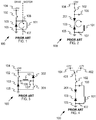
- a prior art control circuit (100) for a brake is shown in FIG. 1 .
- the brake includes an electro-mechanical assembly fitted to the motor, the mechanical construction of which is not illustrated herein.
- the brake includes a shoe held against a braking surface by a spring and an electric solenoid that pushes back against the spring and thus releases the brake.
- a brake coil (101) is a part of the brake.
- a switch (102) and a diode (103) are included in drive electronics. Two wires connect the brake coil (101) to the drive. In operation, the brake coil (101) is energized through switch (102) which is connected to voltage supply (104), in this case a supply of +24V DC.
- the switch (102) can be a normally open contact pair in a relay or alternatively a high-side semiconductor switch may be used.
- the diode (103) may be referred to as a "free-wheeling diode” and is provided in order to protect the switch (102) against excessive voltages when the switch (102) is opened. Under this condition, the current freewheels as indicated by the arrow.
- the prior art control circuit (100) of FIG. 1 can form part of a safe brake control, provided that additional measures are taken.
- the switch (102) must be of a particularly reliable construction and a means must be provided to monitor that the contact has been opened. If these measures are in place, then Safe Brake Control meeting SIL2 criteria set forth in IEC62061 can be achieved.
- the brake is shown as being energized from 24V because this is the standard control voltage used in industrial control systems but other control voltages may be used.
- the inductance of the brake coil (101), which is the wound portion of the electric solenoid of the brake, may be several millihenries, and therefore the time taken for the current to decay when circulating through diode (103) may be hundreds of milliseconds, thereby delaying the application of the brake. This delay may reduce the effectiveness of the brake in fulfilling a safety function. Attempts to reduce this delay have been made with other prior art designs.
- FIG. 2 Another prior art control circuit (100) designed for reducing this delay is illustrated in FIG. 2 .
- the application of the brake in the circuit of FIG. 2 is faster than that of FIG. 1 because when switch (102) opens the current free-wheels as shown through diode (103) and Zener diode (201) which is used to absorb a portion of the energy stored as current in the inductance of the brake coil (101), thereby causing the current in the brake (101) to decay faster.
- prior art control circuit (100) designed in this manner for SIL3 performance is depicted in FIG. 3 . Even if switch (102) fails closed the safety-related control sub-system in the drive will also open switch (301) and thereby apply the brake. Similarly if switch (301) fails closed then switch (102) can still be opened and thus apply the brake.
- This embodiment of prior art control circuit (100) also offers protection from the wire of the positive pole (106) of the brake coil (101) being shorted to +24V or the wire to the negative pole (107) of the brake coil (101) being shorted to ground.
- SIL3 will also require the safety sub-system to detect and report faults, for example by monitoring the voltage at each end of the brake coil (101) and comparing this voltage against the expected value when operating switches (102) and (301). In the terminology of functional safety, this is known as having "diagnostic coverage.” It is feasible to add diagnostic coverage to the circuit of FIG. 3 by, for example, monitoring the voltage across each switch (102) and (301) or by monitoring the voltages at each end of the brake coil (101).
- a further inadequacy in the prior art designs is that of the lack of brake coil power saving.
- a brake coil rated for 24V DC operation will release the brake and allow motion if the applied voltage is 24V within some margin stated by the manufacturer, such as ⁇ 10%.
- the minimum voltage to release the brake is commonly referred to as the "pick" voltage.
- the brake can be held in that state by applying a lower voltage to the brake coil (101) (referred to as the "hold-off voltage"), for example 17V. Since power loss in the brake coil (101) is proportional to the square of the applied voltage, then the reduction in power loss compared with using the 24V is 1-(17/24) 2 ⁇ 50%.
- switch (401) In order to open the brake, switch (401) initially connects switch (102) to 24V (104). After a delay, on the order of seconds, switch (401) changes over to the pole connected to the 17V rail (402).
- the prior art control circuit (100) retains Zener diode (201) (as used in the embodiment of FIG. 2 ). Therefore, this embodiment also features rapid demagnetization of the brake coil (101).
- 17V is a conservative estimate for the hold-off voltage that will work with almost any brake. If a better hold-off voltage for the particular brake is known, then further savings can be made by using that hold-off voltage. In some embodiments, this may be as low as 12V. Generally, it is desirable to make the voltage used in the power saving state be adjustable.
- an alternative means for reducing the voltage applied to the brake in the hold-off phase would be to pulse-width modulate switch (102) in FIG. 1 or switch (102) and/or switch (301) in FIG. 3 .
- switch (102) in FIG. 1 were pulse-width modulated with a duty cycle of 70% then an average of 17V would appear across the brake coil (101).
- direct pulse-width modulation (PWM) of the voltage across the brake coil (101) has two serious disadvantages.
- the first disadvantage is the difficulty and expense of suppressing the consequent switching noise to the level required by regulations on electromagnetic compatibility (EMC).
- a second disadvantage is that PWM cannot practically be applied to switch (102) in the fast demagnetization circuit of FIG. 2 because of the substantial steady-state losses that would arise in Zener diode (201).
- a further requirement or complication to consider is that a drive that includes Safe Brake Control must have two input ports for applying the brake.
- the process sub-system portion of the drive must be able to apply the brake in order to hold the shaft of the motor stationary when the servo amplifier is not holding the shaft by closed loop control and additionally the safety sub-system must be able to apply the brake whenever an unsafe condition has been detected - over-riding the process system when necessary.
- the requirement for two control ports has not been considered in FIGS. 1 - 4 .
- an ideal brake control circuit must perform to a number of criteria.
- the ideal brake control circuit must provide an input port through which the process system in the drive can release the brake using 24V.
- the circuit must subsequently hold the brake off with an adjustable hold-off voltage, and be capable of applying the brake rapidly by demagnetizing the brake coil quickly.
- the ideal brake control circuit must also provide at least one further control port through which the safety sub-system in the drive can independently apply the brake, over-riding the process sub-system if necessary and be able to detect faults in the safety-related parts of the brake control circuit. Further, there is also the ever present need to accomplish these goals at the minimum cost and using the minimum board area.
- a control circuit configured to control an electromechanical brake.
- the control circuit includes: a switching regulator configured to control a magnitude of voltage applied to a brake coil of the electromechanical brake; wherein said switching regulator includes at least one semiconductor switch, one diode, one capacitor and one inductor; the control circuit is configured such that, in operation, at least one signal from a process sub-system specifies the magnitude of the voltage for the brake coil; and at least one brake applying control signal from a safety sub-system can cause the brake coil voltage to be reduced to a level low enough to apply the brake by opening a switch and each brake applying control signal from the safety sub-system has a corresponding diagnostic feedback signal to the safety sub-system that indicates the state of the corresponding switch.
- the switching regulator may be an un-isolating buck regulator.
- a topology of the switching regulator may include a capacitor that is used to transfer power from an input to an output thereof.
- a topology of the switching regulator may include a transformer that is used to transfer power from an input to an output thereof.
- a duty cycle of a switch in the switching regulator may be controlled in an open-loop manner by a pulse width modulated (PWM) control signal from a process sub-system.
- PWM pulse width modulated
- the switching regulator may be coupled to a switching regulator IC that performs closed loop control of the voltage applied to the brake coil.
- the switching regulator may be coupled to a time-weighted feedback network whereby voltage applied to the brake coil can be varied by a control signal from a process system that specifies the time weighting of the time-weighted feedback network.
- a switch in the switching regulator may be configured to be opened by an over-riding first brake applying control signal from the safety sub-system.
- a switch in the switching regulator may be configured to be set to an open state by a first brake applying control signal from the safety sub-system that by-passes the switching regulator and acts on said switch directly.
- the brake coil may be controllable by a second, series connected, switch that is operable by a second control signal from the safety sub-system.
- the brake coil may be coupled to a freewheeling diode and a Zener diode arranged so that current in the brake coil will decay when the second switch is opened.
- a method for controlling an electric motor includes selecting an electric motor configured for control by a control circuit configured to control an electromechanical brake, the control circuit including: a switching regulator configured to control a magnitude of voltage applied to a brake coil of the electromechanical brake; wherein said switching regulator includes at least one semiconductor switch, one diode, one capacitor and one inductor; the control circuit is configured such that, in operation, at least one signal from a process sub-system specifies the magnitude of the voltage for the brake coil; and at least one brake applying control signal from a safety sub-system can cause the brake coil voltage to be reduced to a level low enough to apply the brake by opening a switch and each brake applying control signal from the safety sub-system has a corresponding diagnostic feedback signal to the safety sub-system that indicates the state of the corresponding switch; and, applying at least one control signal to cause the electromechanical brake to brake the electric motor.
- a system including an electric motor configured for control by a control circuit includes: an electric motor configured with an electromechanical brake, the electromechanical brake in communication with the control circuit, the control circuit including a switching regulator configured to control a magnitude of voltage applied to a brake coil of the electromechanical brake; wherein said switching regulator includes at least one semiconductor switch, one diode, one capacitor and one inductor; the control circuit is configured such that, in operation, at least one signal from a process sub-system specifies the magnitude of the voltage for the brake coil; and at least one brake applying control signal from a safety sub-system can cause the brake coil voltage to be reduced to a level low enough to apply the brake by opening a switch and each brake applying control signal from the safety sub-system has a corresponding diagnostic feedback signal to the safety sub-system that indicates the state of the corresponding switch; and apparatus configured to provide input to the safety sub-system and cause generation of the at least one brake applying signal.
- the brake coil may be controllable by a second, series connected, switch that is operable by a second control signal from the safety sub-system.
- the electric motor may include one of an induction motor; a synchronous motor; a shunt motor; a separately excited motor; a series motor; a permanent magnet motor; a compounded motor; a stepper motor; a brushless DC motor; a hysteresis motor; a reluctance motor; and a universal motor.
- the system may be configured for implementation in at least one of food and beverage; packaging and converting; pharmaceutical; material forming; medical laboratory and automation; robotics; printing; labeling; aerospace; tire and rubber; postal sorting; automated vehicles; oil and gas processing; cranes, hoist and elevators.
- the technology disclosed herein assures safe operation and power savings sought by associated standards for performance, such as IEC 62061, ISO 13849-1 and ISO 13849-2.
- FIGS. 5-13 depict embodiments of control circuits implementing designs that achieve the intended performance.
- the central elements of a first embodiment are shown in FIG. 5 .
- a switching regulator (507) is supplied 24V from voltage supply (104).
- the switching regulator (507) generates an output voltage at the positive pole (106) of the brake coil (101) that can be varied from a reduced voltage (for example, 12V), up to nearly 24V.
- signal RELEASE_H_PROCESS (501) is controlled by the process sub-system.
- Signal RELEASE_H_SAFE (502) is controlled by the safety sub-system. Release high process signal (501) and release high safe signal (502) must be true for the switching regulator (507) to operate, as otherwise the output voltage at the positive pole (106) will be zero.
- Signal STATUS_H_SAFE (503) informs the safety sub-system whether the switch in the regulator (507) has opened.
- a low-side switch (508) can be turned on by the safety sub-system using signal RELEASE_L_SAFE (505) and the status of the switch, namely whether the switch has opened, is indicated via signal STATUS_L_SAFE (506).
- Signal VOUT_PWM_PROCESS (504) controls the magnitude of the output of the buck regulator (507) at the positive pole (106).
- Signal VOUT_PWM_PROCESS (504) is a pulse-width modulated signal and higher duty cycles cause the output voltage at the positive pole (106) to be larger.
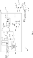
- the embodiment of the control circuit (500) depicted in FIG. 6 is the same as FIG. 5 but shows the switching regulator (507) in more detail.
- the high-side switch (102) is a MOSFET which, in combination with a free-wheeling diode (609) and a filter comprising inductor (601) and capacitor (602), forms a buck regulator (which may also be referred to as a "step-down regulator").
- This type of switching regulator (507) is well-known and the operating principle will not be described further.
- the buck regulator is controlled by a switching regulator control IC (604) such as type LM5085 from Texas Instruments.
- the switching regulator control IC (604) implements an inner current control loop and also over-current protection in conjunction with a resistor (610) to sense the current and a related signal (611) that is proportional to current but which is referred to +24V the voltage supply (104).
- Switching regulator control IC (604) is enabled when both signal RELEASE_H_PROCESS (501) and signal RELEASE_H_SAFE (502) are true by controlling the enable input of the switching regulator (604) using a wired-AND circuit (605).
- Block (606) sets signal STATUS_H_SAFE (503) when switch (102) is off; operation of this circuit is similar to block (508) which will be described with reference to FIG. 8 .
- Signals STATUS_H_SAFE (503) and STATUS_L_SAFE (506) are monitored by the safety control sub-system in the drive (not illustrated), which inserts short test pulses, or rather test notches, into signals RELEASE_H_SAFE (502) and RELEASE_L_SAFE (506) to verify the opening of the respective switches.
- the test pulses disconnect the brake coil (101) too briefly to have any significant mechanical effect on the brake.
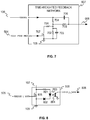
- R(705) in combination with C(706) are included to permit highfrequency feedback.
- C(703) filters the feedback fraction to prevent steps from appearing in the output voltage (106) when gain switch (707) is switched.
- signal VOUT_PWM_PROCESS (504) controls the output voltage at the positive pole (106) of the brake (101).
- the low side switch circuit (508) is depicted as a MOSFET (805) and in a practical implementation a self-protecting MOSFET is likely to be used.
- MOSFET (805) turns off, there is a voltage across it and current flows through R(801), the diode portion of opto-isolator (804) and backwards through Zener diode (802).
- the opto-isolator (804) sends a pulse to the safety control system, not shown, when the MOSFET (805) turns off and by this means diagnostic coverage may be achieved.
- the embodiment depicted in FIG. 5 achieves power saving control of the brake with a variable voltage using a switching regulator controlled by just one PWM signal (504) and secondly achieves two-channel safe brake control and power saving brake control using only two power switches whereby one of the switches also acts as the switch in the switching regulator.
- the drive need not contain a safety control sub-system but does allow safe brake control to be achieved in conjunction with an external safety control device such as a safety PLC.
- the switching regulator (507) is retained but now the low side switch circuit (508) is replaced by a relay (902) with two normally open contacts.
- a second similar relay (901) is inserted between the output of the switching regulator (507) and the positive pole (106) of the brake (101). Both signals RELEASE_SAFE_H (502) and RELEASE_SAFE_L (505), which are controlled by an external safety system, are driven for the brake to be released.
- each relay (901) and (902) is brought out to the external safety system as signals STATUS_H_SAFE (503) and STATUS_L_SAFE (506) so that the operation of the relays can be monitored, i.e. to provide diagnostic coverage.
- STATUS_H_SAFE 503
- STATUS_L_SAFE 506
- a "simple circuit” uses resistors, capacitors, diodes, transistors and relays but excludes integrated circuits.
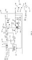
- the designer may additionally or alternatively arrange for the output of the wired-AND circuit (605) to act more directly on the high-side MOSFET (102), by for example, using a simple circuit to over-ride control of the gate of the high-side MOSFET (102). This is illustrated in FIG.
- MOSFET 10 which adds MOSFETS (1001), (1002), (1003) and resistors (1004), (1005), (1008), (1009).
- signals (501) and (502) are high then signal (1006) is high and this causes MOSFET (1001) to be ON thereby causing MOSFET (1002) to be OFF, thereby allowing the gate of MOSFET (1003) to be pulled to its source potential via resistor (1005) so that MOSFET (1003) is OFF and consequently switching regulator control IC (604) can control the gate of MOSFET (102).
- the output signal (1006) of the wired AND gate (605) is shown as being additionally connected to RT/ENABLE input of the switching regulator control IC (604) thereby activating the slow-start of IC (604) when signals (501) and (502) are high, this is desirable but not essential and therefore resistor (1008) could be omitted.
- FIG. 6 and FIG. 10 There are many advantages to using a closed-loop voltage regulator (507) as depicted in FIG. 6 and FIG. 10 .
- the closed loop action ensures that the hold-off value of the brake voltage at the positive pole (106) does not depend on how much current is drawn by the brake nor does it depend on the actual value of the 24V control supply and therefore this scheme is preferred in products that are sold on the general market. If, however, the current drawn by the brake and the value of control supply are known, fixed, values then it is possible to dispense with closed-loop regulation as shown in the fourth preferred embodiment of FIG. 11 . Comparing FIG. 11 with the first embodiment of FIG.
- the signal VOUT_PWM_PROCESS (504) is presented to a three-input wired AND gate (605) which controls the main high-side switch (102) directly using a level-translating network (1001), (1102), (1003), (1004), (1005) of FIG. 10 .
- the embodiment of FIG. 11 has no PWM regulator IC (604) nor does it have a time-weighted feedback network (607).
- the ratio of ⁇ ON time of high-side switch (102) ⁇ / ⁇ ON time of main switch (102) + OFF time of main switch (102) ⁇ is called the duty cycle.
- the output voltage at the positive pole (106) is approximately equal to the input voltage (104) multiplied by the duty cycle.
- the duty cycle of the high-side switch (102) is in turn controlled by and is essentially the same as the duty of the signal VOUT_PWM_PROCESS (504). For example if the duty cycle of signal VOUT_PWM_PROCESS (504) is 71% as sketched by signal (504) in FIG. 11 then the voltage at the positive pole (106) is equal to the 24V supply (104) multiplied by 0.71 which equals 17V.
- the first, second, third and fourth embodiments all apply the brake using switches of moderate intrinsic reliability but achieve low PFH D values for the safe brake control function by having two such switches in series with the brake combined with detection signals (503) and (506) of the failure of each switch (102) and (805). If the intrinsic reliability of either switch or of both switches could be increased then an even higher overall PFH D values could be obtained (see equation D.1 in IEC 62061 Edition 1.1 2012-11 ). The failure rates of capacitors are far lower than of semiconductor switches (102), (805) or relays (901), (902).
- the regulator (507) is be modified from the buck topology of FIG. 6 to the Zeta topology shown in FIG. 12 and also differs from FIG. 6 by the addition of capacitor (1201) and inductor (1202).
- the Zeta converter topology is formed from elements (102), (601), (602), (603), (1201) and (1202).
- signal (1203) is pulled to 24V and there can be no sustained power transfer through capacitor (1201) and therefore the brake coil (101) will be de-energized thereby applying said brake.
- the fifth embodiment allows the development of power-saving, safe brake control with increased PFH D by eliminating failure of the high-side switch (102) from PFH D calculations.
- FIG. 13 is derived from FIG. 6 by adding transformer (1301) and diodes (1302) and (1303).
- the essential elements of the single transistor forward converter are the high-side switch (102), transformer (1301), diodes (609), (1301), (1302), inductor (601) and capacitor (602).
- Forward converters are well-known circuits whose normal operation will not be described further.
- signal (1304) is pulled to 24V and there can be no sustained power transfer through transformer (1301) and therefore the brake coil (101) will be de-energized thereby applying said brake.
- the duty cycle of high-side switch (102) must be limited to 50% to allow the flux in transformer (1301) to be reset via diode (1302) at every switching cycle and therefore the turns ratio (1305) must step-up the output so that 24V can be applied to the brake, this also has the further advantage of permitting operation when the supply voltage (104) is less than the 24V nominal value.
- the sixth embodiment allows the development of power-saving, safe brake control with increased PFH D by eliminating failure of the high-side switch (102) from PFH D calculations.
- the two inductors (601) and (1202) of FIG. 12 could be combined into a single coupled inductor in order save cost.
- Further possible variants of the fifth embodiment could use the same or similar components to implement alternative capacitor-coupled converter circuits such as SEPIC or Cuk both of which are well-known and will not be described further.
- a more direct method, such as that shown in FIG. 10 of controlling the high side switch (102) could also be applied to FIG. 12 or FIG. 13 .
- the output of the switching regulator (507) is referred to ground
- a variant would be to disconnect the output winding of transformer (1301) so that the brake coil (101) is driven by a fully isolated source, this would be advantageous because accidental grounding of either side of the brake coil would have no effect on the safe control of the brake.
- the open loop control of the fourth preferred embodiment shown in FIG. 11 could be applied to fifth embodiment of FIG. 12 or sixth embodiment of FIG. 13 .
- the sixth embodiment of FIG. 13 uses a transformer isolated version of the buck topology but alternative topologies such as the fly-back circuit could be used.
- inductor (1202) with a two winding inductor; this principle also applies to SEPIC and Cuk variants.
- All of the preferred embodiments regulate the voltage at the positive pole (106) of the brake (101) with respect to ground but the circuits could be re-arranged to regulate the voltage at the negative pole (107) with respect the +24V supply (104) without change to the principles of operation.
- power saving and other related terms generally refer to reduced power use for the technology disclosed herein when considered in comparison to prior art systems. This is not to imply the technology disclosed herein provides power storage.
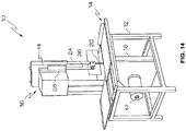
- FIG. 14 is an illustration of a system (5) that includes equipment (8) that makes use of an electric drive motor (52) configured with a power-saving, safe, brake control circuit (500) as disclosed herein.
- the equipment (8) is provided as part of a food processing station (10).
- the food processing station (10) includes band saw (16).
- Food processing apparatus such as band saw (16) are commonly used for cutting meat products of a variety of sizes.
- band saw (16) includes a frame (12) upon which is mounted a support surface (14) for positioning meat products to be cut.
- a housing (18) extends above support surface (14) and housing (18) also extends below support surface (14).
- a band saw blade (20) passes through a plane defined by support surface (14) and extends around wheel members (not shown) located with housing (18) for being drivingly rotated by such wheel members.
- Drive motor (52) may be connected for rotating a drive wheel in housing (18).
- a blade guard (24) extends around the cutting edge of blade (20) and downward from housing (18) toward support surface (14).
- Blade guard (24) is connected to a guide bar (26) which extends upward toward housing (18) and through a guide assembly (28) which is mounted to housing (18).
- Guide bar (26) may be positioned by sliding within guide assembly (28) such that guide bar (26) can be moved upward or downward through such guide assembly if a sufficient moving force is applied thereto.
- guide assembly (28) engages guide bar (26) with sufficient force to hold guide bar (26) and blade guard (24) in position. Because blade guard (24) is connected to guide bar (26) for movement therewith, the length of band saw blade (20) which is protected by the blade guard (24) can be varied by varying the position of guide bar (26) relative to guide assembly (28).
- control circuit (500) implements control circuit (500) as a controller for controlling drive motor (52).
- control circuit (500) may be configured to detect interference (i.e., a safety hazard) with equipment (8), such as contact of the operator with the blade (20).
- a signal is sent to the control circuit (500).
- the control circuit (500) then initiates the safe shutdown of the drive motor (52) in accordance with the teachings disclosed herein.
- the system (5) is shown as implementing a food processing station (10) including a band saw (16), any type of equipment deemed appropriate may make use of the drive motor (52) configured with the control circuit (500) as disclosed herein.
- the drive motor may be used in industries or settings involved with food and beverage; packaging and converting; pharmaceutical; material forming; medical laboratory and automation; robotics; printing; labeling; aerospace; tire and rubber; postal sorting; automated vehicles; oil and gas; and any other environment deemed appropriate.
- the drive motor may include any type of motor deemed appropriate.
- the drive motor be driven by alternating current (AC) or direct current (DC).
- the drive motor may include, without limitation: an induction motor; a synchronous motor; a shunt motor; a separately excited motor; a series motor; a permanent magnet motor; a compounded motor; a stepper motor; a brushless DC motor; a hysteresis motor; a reluctance motor; a universal motor; and any one or more of a variety of other types of motors.
- the motor may cause rotary motion or linear motion directly or indirectly, such as through mechanical linkages.
- the drive motor may include any type of material deemed appropriate. For example, stainless steel, steel alloys, cast iron and/or other materials such as polymeric materials may be used.
- teachings herein may be used to supply a kit for retrofit of existing equipment.
- an existing brake controller may be replaced with a control circuit as described herein.
- Additional components such as replacement power supplies and other modifications as deemed appropriate may be included.
- teachings herein are configured for implementation in a particular industry, this is considered to involve arrangement of the technology with production equipment as may be used within that industry. Very often, this involves specialized equipment designed for particular applications. Examples of industries making use of specialized equipment that may benefit from the teachings herein include, without limitation, at least one of food and beverage; packaging and converting; pharmaceutical; material forming; medical laboratory and automation; robotics; printing; labeling; aerospace; tire and rubber; postal sorting; automated vehicles; oil and gas processing industries; cranes, hoist and elevators.
- modifications may be designed, incorporated or implemented according to the needs of a user, designer, manufacturer or other similarly interested party.
- the modifications may be intended to meet a particular standard of performance considered important by that party. Therefore, standards of performance or adequacy are to be judged by such a party.
- the articles “a,” “an,” and “the” are intended to mean that there are one or more of the elements.
- the adjective “another,” when used to introduce an element, is intended to mean one or more elements.
- the terms “including” and “having” are intended to be inclusive such that there may be additional elements other than the listed elements.
- the term “exemplary” is not intended to imply a superlative example. Rather, “exemplary” refers to an embodiment that is one of many possible embodiments.
Landscapes
- Engineering & Computer Science (AREA)
- Power Engineering (AREA)
- Physics & Mathematics (AREA)
- Electromagnetism (AREA)
- General Engineering & Computer Science (AREA)
- Mechanical Engineering (AREA)
- Stopping Of Electric Motors (AREA)
Claims (15)
- Un circuit (500) de commande configuré pour commander un frein électromécanique, le circuit (500) de commande comprenant :un régulateur à commutation configuré pour contrôler une amplitude de tension appliquée à une bobine (101) de frein du frein électromécanique, où ledit régulateur à commutation comprend au moins un commutateur (102) à semi-conducteur, une diode (609), un condensateur (602) et un inducteur (601);où le circuit (500) de commande est configuré de telle façon que, en fonctionnement, au moins un signal (504) de commande d'un sous-système du processus spécifie l'amplitude de la tension pour la bobine (101) de frein; etau moins un signal (502, 505) de commande d'actionnement du frein provenant d'un sous-système de sécurité qui provoque la réduction de la tension de la bobine de frein à un niveau qui est effectivement zéro, freinant ainsi en ouvrant un commutateur (102, 508), où chaque signal de commande de freinage du sous-système de sécurité possède un signal (503, 506) de retour de diagnostic correspondant vers le sous-système de sécurité qui indique l'état du commutateur (102, 508) correspondant;caractérisé en ce que le régulateur à commutation est couplé à un réseau (607) de retour pondéré dans le temps à un avis de retour (FB) du régulateur à commutation au moyen duquel la tension appliquée à la bobine (101) de frein peut être changée par le signal (504) de commande provenant du sous-système du processus qui spécifie la pondération temporelle du réseau (607) de retour pondéré dans le temps.
- Le circuit de commande de la revendication 1, où le régulateur à commutation est un régulateur abaisseur non isolant.
- Le circuit de commande de la revendication 1 ou de la revendication 2, où une topologie du régulateur à commutation comprend un condensateur (1201) qui est utilisé pour transférer l'alimentation d'une entrée vers une sortie de celui-ci.
- Le circuit de commande de n'importe laquelle des revendications 1 à 3, où une topologie du régulateur à commutation comprend un transformateur (1301) qui est utilisé pour transférer l'alimentation d'une entrée vers une sortie de celui-ci.
- Le circuit de commande de n'importe laquelle des revendications 1 à 4, où un cycle de tâches d'un commutateur (102) du régulateur à commutation est commandé en boucle ouverte par un signal (504) de commande à largeur d'impulsion modulée (PWM) provenant du sous-système du processus.
- Le circuit de commande de n'importe laquelle des revendications 1 à 5, où le régulateur à commutation est couplé à un circuit intégré (604) de régulateur à commutation qui exécute une commande de boucle fermée de la tension appliquée à la bobine (101) de frein.
- Le circuit de commande de n'importe laquelle des revendications 1 à 6, où un commutateur (102) dans le régulateur à commutation est configuré pour être ouvert par un signal (502) de commande prépondérant appliquant le premier frein depuis le système de sécurité.
- Le circuit de commande de n'importe laquelle des revendications 1 à 7, où un commutateur (102) dans le régulateur à commutation est configuré pour être réglé sur un état ouvert par un signal (502) de commande prépondérant appliquant le premier frein depuis le système de sécurité qui contourne le régulateur à commutation et agit directement sur ledit commutateur (102).
- Le circuit de commande n'importe laquelle des revendications 1 à 8, où la bobine (101) de frein est contrôlable par un second commutateur (508), raccordé en série, qui peut fonctionner au moyen d'un second signal (505) de commande provenant du sous-système de sécurité.
- Le circuit de commande de n'importe laquelle des revendications 1 à 9, où la bobine (101) de frein est couplée à une diode (103) tournant à vide et à une diode (201) Zener arrangées de telle façon que le courant dans la bobine (101) de frein chute lorsque le second commutateur (508) est ouvert.
- Une méthode pour commander un moteur électrique, la méthode comprenant :sélectionner un moteur électrique configuré pour le contrôle par un circuit de commande configuré pour commander un frein électromécanique, le circuit de commande comprenant :un régulateur à commutation configuré pour commander une amplitude de tension appliquée à une bobine (101) de frein du frein électromécanique, où ledit régulateur à commutation comprend au moins un commutateur (102) à semi-conducteur, une diode (609), un condensateur (602) et un inducteur (601) et où le circuit de commande est configuré de façon que, en fonctionnement, au moins un signal (504) de commande provenant d'un sous-système du processus spécifie l'amplitude de la tension pour la bobine(101) de frein; etau moins un signal (502, 505) de commande d'actionnement du frein provenant d'un sous-système de sécurité qui provoque la réduction de la tension de la bobine de frein à un niveau qui est effectivement zéro, freinant ainsi en ouvrant un commutateur (102, 508) et chaque signal de commande de freinage du sous-système de sécurité possède un signal (503, 506) de retour de diagnostic correspondant vers le sous-système de sécurité qui indique l'état du commutateur (102, 508) correspondant; etappliquant au moins un signal de commande pour faire que le frein électromécanique freine le moteur électrique;caractérisé en ce que le régulateur à commutation est couplé à un réseau (607) de retour pondéré dans le temps à un avis de retour (FB) du régulateur à commutation au moyen duquel la tension appliquée à la bobine (101) de frein peut être changée par le signal (504) de commande provenant du sous-système du processus qui spécifie la pondération temporelle du réseau (607) de retour pondéré dans le temps.
- Un système comprenant un moteur électrique configuré pour le contrôle par un circuit de commande, le système comprenant :un moteur électrique configuré avec un frein électromécanique, le frein électromécanique en communication avec le circuit de commande, le circuit de commande comprenant un régulateur à commutation configuré pour commander une amplitude de tension appliquée à une bobine de frein du frein électromécanique, où ledit régulateur à commutation comprend au moins un commutateur à semi-conducteur, une diode, un condensateur et un inducteur et où le circuit de commande est configuré de façon que, en fonctionnement, au moins un signal provenant d'un sous-système du processus spécifie l'amplitude de la tension pour la bobine de frein;au moins un signal de commande d'actionnement du frein provenant d'un sous-système de sécurité qui provoque la réduction de la tension de la bobine de frein à un niveau qui est effectivement zéro, freinant ainsi en ouvrant un commutateur et chaque signal de commande de freinage du sous-système de sécurité possède un signal de retour de diagnostic correspondant vers le sous-système de sécurité qui indique l'état du commutateur correspondant; etun appareil configuré pour fournir des données au sous-système de sécurité et causer la génération d'au moins un signal de freinage;caractérisé en ce que le régulateur à commutation est couplé à un réseau (607) de retour pondéré dans le temps à un avis de retour (FB) du régulateur à commutation au moyen duquel la tension appliquée à la bobine (101) de frein peut être changée par un signal (504) de commande provenant du sous-système du processus qui spécifie la pondération temporelle du réseau (607) de retour pondéré dans le temps.
- Le système de la revendication 12, où la bobine de frein est contrôlable par un second commutateur (508), raccordé en série, qui peut fonctionner au moyen d'un second signal (505) de commande provenant du sous-système de sécurité.
- Le système de la revendication 12 ou de la revendication 13, où le moteur électrique comprend l'un des moteurs suivants : un moteur à induction; un moteur synchrone ; un moteur en dérivation; un moteur excité séparément; un moteur en série ; un moteur à aimant permanent ; un moteur composé ; un moteur pas-à-pas; un moteur à courant continu sans balai; un moteur à hystérésis; un moteur à réluctance et un moteur universel.
- Le système de n'importe laquelle des revendications 12 à 14, configuré pour sa mise en œuvre dans au moins l'un des éléments concernant la nourriture et les boissons; emballage et conversion; industrie pharmaceutique; mise en forme des matériaux ; laboratoire médical et automatisation; robotique; imprimerie; étiquetage; aéronautique; pneus et caoutchouc; tri postal; véhicules automatisés; traitement du pétrole et du gaz; grues; treuils et élévateurs.
Applications Claiming Priority (2)
| Application Number | Priority Date | Filing Date | Title |
|---|---|---|---|
| US201662286345P | 2016-01-23 | 2016-01-23 | |
| PCT/US2017/014393 WO2017127720A1 (fr) | 2016-01-23 | 2017-01-20 | Procédé et appareil pour réaliser une commande à sécurité intégrée et à économies d'énergie électrique d'un frein électromécanique |
Publications (2)
| Publication Number | Publication Date |
|---|---|
| EP3406024A1 EP3406024A1 (fr) | 2018-11-28 |
| EP3406024B1 true EP3406024B1 (fr) | 2020-11-11 |
Family
ID=57995277
Family Applications (1)
| Application Number | Title | Priority Date | Filing Date |
|---|---|---|---|
| EP17704126.6A Active EP3406024B1 (fr) | 2016-01-23 | 2017-01-20 | Procédé et appareil pour réaliser une commande à sécurité intégrée et à économies d'énergie électrique d'un frein électromécanique |
Country Status (3)
| Country | Link |
|---|---|
| US (1) | US10520050B2 (fr) |
| EP (1) | EP3406024B1 (fr) |
| WO (1) | WO2017127720A1 (fr) |
Families Citing this family (12)
| Publication number | Priority date | Publication date | Assignee | Title |
|---|---|---|---|---|
| US10615727B2 (en) * | 2018-08-27 | 2020-04-07 | General Electric Company | Dynamic brake circuit assembly for a wind turbine |
| PL3632760T3 (pl) * | 2018-10-05 | 2022-03-14 | Chr. Mayr Gmbh + Co. Kg | Prewencyjna kontrola działania elektromagnetycznego hamulca sprężynowego |
| JP7014140B2 (ja) | 2018-11-28 | 2022-02-01 | オムロン株式会社 | 電磁ブレーキ制御装置及び制御装置 |
| WO2020107128A1 (fr) * | 2018-11-30 | 2020-06-04 | Ats Automation Tooling Systems Inc. | Système et procédé de commande de moteur électrique dans un environnement de fabrication |
| US11137727B2 (en) * | 2019-04-04 | 2021-10-05 | Swivel-Link, LLC | Validation device for testing a machinery safety system |
| CN111425540B (zh) * | 2020-03-06 | 2024-12-03 | 奥创动力传动(深圳)有限公司 | 一种电磁制动器控制装置 |
| US11114842B1 (en) * | 2020-05-27 | 2021-09-07 | Rockwell Automation Technologies, Inc. | Dual PWM relay driver with diagnostics for functional safety system |
| US11518033B2 (en) | 2020-07-06 | 2022-12-06 | Kollmorgen Corporation | Method and apparatus for safely limiting the motion of a motor |
| CN112803732A (zh) * | 2021-02-05 | 2021-05-14 | 惠州市有为创科电子有限公司 | 一种宽范围调压控制系统及其控制方法 |
| CN119231971A (zh) * | 2023-06-30 | 2024-12-31 | 广东美的白色家电技术创新中心有限公司 | 直流降压电路、抱闸机构和电机 |
| CN116774638A (zh) * | 2023-08-21 | 2023-09-19 | 北京领创医谷科技发展有限责任公司 | 一种应用于体外能控器的开关机电路 |
| CN118707329B (zh) * | 2024-06-25 | 2026-01-23 | 贵州航天林泉电机有限公司 | 一种调压器保护功能测试的静止模拟装置及设计方法 |
Family Cites Families (31)
| Publication number | Priority date | Publication date | Assignee | Title |
|---|---|---|---|---|
| GB1315589A (en) * | 1970-01-21 | 1973-05-02 | Hitachi Ltd | Control apparatus for an elevator car |
| EP0658832B1 (fr) | 1993-12-16 | 2000-04-26 | Siemens Aktiengesellschaft | Dispositif pour commander une machine-outil ou un robot |
| US5592071A (en) * | 1995-01-11 | 1997-01-07 | Dell Usa, L.P. | Method and apparatus for self-regeneration synchronous regulator |
| EP0742503B1 (fr) | 1995-05-11 | 2000-08-23 | Siemens Aktiengesellschaft | Dispositif pour la commande numérique d'une machine-outil ou d'un robot |
| US6039151A (en) * | 1997-04-25 | 2000-03-21 | Inventio Ag | Backup apparatus for a hydraulic elevator brake control |
| DE19739736A1 (de) | 1997-09-11 | 1999-03-18 | Heidenhain Gmbh Dr Johannes | Verfahren und Schaltungsanordnung zur sicheren Ausführung von sicherheitsrelevanten Funktionen |
| DE19834863A1 (de) | 1998-08-01 | 2000-02-03 | Heidenhain Gmbh Dr Johannes | Verfahren zur sicheren Datenübertragung zwischen einer numerischen Steuerung und einem räumlich getrennten Gerät |
| US6285146B1 (en) * | 1998-08-07 | 2001-09-04 | Nidec America Corporation | Apparatus and method of regulating the speed of a brushless DC motor |
| DE19927851B4 (de) | 1999-06-18 | 2008-11-13 | Danfoss Drives A/S | Verfahren zum Überwachen eines Drehwinkelaufnehmers an einer elektrischen Maschine |
| DE19937737C2 (de) | 1999-08-10 | 2003-10-30 | Pilz Gmbh & Co | Vorrichtung zum sicheren Überwachen der Drehbewegung einer Welle |
| US6486674B2 (en) | 2000-01-27 | 2002-11-26 | Siemens Aktiengesellschaft | Method for detecting faults on safety oriented sensors |
| DE10154690A1 (de) | 2001-11-09 | 2003-05-28 | Lenze Drive Systems Gmbh | Verfahren zur sicherheitsgerichteten Drehzahlüberwachung eines geregelten Antriebsmotors |
| DE10215428A1 (de) | 2002-04-08 | 2003-10-23 | Heidenhain Gmbh Dr Johannes | Verfahren zur Bestimmung der Rotorlage eines Synchronmotors |
| US7019474B2 (en) * | 2003-03-26 | 2006-03-28 | Airport Lighting Company Of New York | Constant current regulator using IGBT's with simplified timing |
| FI20031647A0 (fi) * | 2003-11-12 | 2003-11-12 | Kone Corp | Hissin jarrun ohjauspiiri |
| DE102004055971B8 (de) | 2004-11-19 | 2012-06-21 | Kw-Software Gmbh | Verfahren und Vorrichtung zur sicheren Parametierung gemäß IEC 61508 SIL 1 bis 3 oder EN 954-1 Kategorie 1 bis 4 |
| DE102005048601B3 (de) | 2005-10-06 | 2007-04-05 | Pilz Gmbh & Co. Kg | Vorrichtung und Verfahren zum fehlersicheren Auswerten eines Stellungsgebers, insbesondere eines Potentiometers |
| DE102006042038B3 (de) | 2006-09-07 | 2008-02-07 | Siemens Ag | Verfahren und Vorrichtung zur sicheren Drehmomentbegrenzung |
| EP2303747B1 (fr) | 2008-06-17 | 2013-04-10 | Otis Elevator Company | Commande sûre d un frein au moyen de dispositifs de commande de faible puissance |
| DE102008058303B4 (de) * | 2008-11-19 | 2022-08-11 | Sew-Eurodrive Gmbh & Co Kg | Verfahren zum Betreiben eines Antriebs und Antriebssystem |
| US8432140B1 (en) * | 2012-02-13 | 2013-04-30 | Microchip Technology Incorporated | Dual mode boost regulator |
| US9407187B2 (en) * | 2012-06-28 | 2016-08-02 | General Electric Company | System and method for improving response time of a braking unit |
| JP5758864B2 (ja) * | 2012-11-08 | 2015-08-05 | ファナック株式会社 | ブレーキの状態を解放状態から締結状態に迅速に変更するブレーキ駆動制御装置 |
| US20140210439A1 (en) * | 2013-01-29 | 2014-07-31 | Richtek Technology Corporation | Switching Regulator and Control Circuit Thereof |
| US9240740B2 (en) * | 2013-05-30 | 2016-01-19 | The Boeing Company | Active voltage controller for an electric motor |
| US9385637B2 (en) * | 2014-05-21 | 2016-07-05 | Hamilton Sundstrand Corporation | Brake controller |
| CN104210982B (zh) | 2014-08-22 | 2016-05-25 | 上海吉亿电机有限公司 | 一种电梯抱闸控制系统及控制方法 |
| WO2016069802A1 (fr) * | 2014-10-28 | 2016-05-06 | Advanced Charging Technologies, LLC | Circuit électrique de fourniture d'énergie à des dispositifs électroniques grand public |
| US10056833B2 (en) * | 2015-05-12 | 2018-08-21 | Hamilton Sundstrand Corporation | Voltage regulator for inductive loads |
| US11108435B2 (en) * | 2015-06-03 | 2021-08-31 | Apple Inc. | Inductive power receiver |
| US20170099011A1 (en) * | 2015-10-02 | 2017-04-06 | Advanced Charging Technologies, LLC | Electrical circuit for delivering power to consumer electronic devices |
-
2017
- 2017-01-20 EP EP17704126.6A patent/EP3406024B1/fr active Active
- 2017-01-20 WO PCT/US2017/014393 patent/WO2017127720A1/fr not_active Ceased
- 2017-01-20 US US15/411,759 patent/US10520050B2/en active Active
Non-Patent Citations (1)
| Title |
|---|
| None * |
Also Published As
| Publication number | Publication date |
|---|---|
| WO2017127720A1 (fr) | 2017-07-27 |
| US20170211640A1 (en) | 2017-07-27 |
| US10520050B2 (en) | 2019-12-31 |
| EP3406024A1 (fr) | 2018-11-28 |
Similar Documents
| Publication | Publication Date | Title |
|---|---|---|
| EP3406024B1 (fr) | Procédé et appareil pour réaliser une commande à sécurité intégrée et à économies d'énergie électrique d'un frein électromécanique | |
| KR102243467B1 (ko) | 전기 자동차를 위한 인버터 | |
| EP2303747B1 (fr) | Commande sûre d un frein au moyen de dispositifs de commande de faible puissance | |
| EP2725435B1 (fr) | Commande d'une fonction de sécurité d'une machine électrique | |
| US5744921A (en) | Control circuit for five-phase brushless DC motor | |
| US11482951B2 (en) | Brake driving control circuit and breakdown detection method thereof | |
| US20050052150A1 (en) | Failsafe operation of active vehicle suspension | |
| US10587193B2 (en) | Synchronous buck regulator with short circuit to voltage source protection | |
| US11164704B2 (en) | Motor device for a switch drive of an electric switch | |
| CN111010051A (zh) | 电动机驱动装置 | |
| JP6502554B1 (ja) | 電磁切換弁位置検出システム | |
| DE102008058303B4 (de) | Verfahren zum Betreiben eines Antriebs und Antriebssystem | |
| CN101107774A (zh) | 用于电机的供电装置、用于驱动电机的方法 | |
| EP2668718B1 (fr) | Dispositif de commutation | |
| EP2503682B1 (fr) | Agencement de circuit | |
| CN101515777A (zh) | 电子部件安装装置 | |
| EP1805885B1 (fr) | Frein electromagnetique, dispositif de commande sure d'un frein electromagnetique, moteur electrique et frein | |
| JP6806609B2 (ja) | 電源制御装置、および、電源制御方法 | |
| JP2000233090A (ja) | ミシンの制御装置 | |
| JP3376812B2 (ja) | エレベーターのブレーキ制御装置 | |
| EP1441372A2 (fr) | Appareil et méthode de commande pour actionneur | |
| EP4703540A1 (fr) | Dispositif d'entraînement de serrure de porte électrique basé sur un générateur d'impulsions de courant et une source de courant à mode commuté avec sortie dépendant de la charge | |
| CN113883193B (zh) | 电磁止动闸及其控制装置和方法以及电机 | |
| CN114977148A (zh) | 抱闸供电电路及用于驱动机器人制动器的抱闸供电方法 | |
| KR101754972B1 (ko) | 동작소음을 줄여주는 엘리베이터 안전회로 |
Legal Events
| Date | Code | Title | Description |
|---|---|---|---|
| STAA | Information on the status of an ep patent application or granted ep patent |
Free format text: STATUS: UNKNOWN |
|
| STAA | Information on the status of an ep patent application or granted ep patent |
Free format text: STATUS: THE INTERNATIONAL PUBLICATION HAS BEEN MADE |
|
| PUAI | Public reference made under article 153(3) epc to a published international application that has entered the european phase |
Free format text: ORIGINAL CODE: 0009012 |
|
| STAA | Information on the status of an ep patent application or granted ep patent |
Free format text: STATUS: REQUEST FOR EXAMINATION WAS MADE |
|
| 17P | Request for examination filed |
Effective date: 20180706 |
|
| AK | Designated contracting states |
Kind code of ref document: A1 Designated state(s): AL AT BE BG CH CY CZ DE DK EE ES FI FR GB GR HR HU IE IS IT LI LT LU LV MC MK MT NL NO PL PT RO RS SE SI SK SM TR |
|
| AX | Request for extension of the european patent |
Extension state: BA ME |
|
| DAV | Request for validation of the european patent (deleted) | ||
| DAX | Request for extension of the european patent (deleted) | ||
| STAA | Information on the status of an ep patent application or granted ep patent |
Free format text: STATUS: EXAMINATION IS IN PROGRESS |
|
| 17Q | First examination report despatched |
Effective date: 20191129 |
|
| GRAP | Despatch of communication of intention to grant a patent |
Free format text: ORIGINAL CODE: EPIDOSNIGR1 |
|
| STAA | Information on the status of an ep patent application or granted ep patent |
Free format text: STATUS: GRANT OF PATENT IS INTENDED |
|
| INTG | Intention to grant announced |
Effective date: 20200603 |
|
| GRAS | Grant fee paid |
Free format text: ORIGINAL CODE: EPIDOSNIGR3 |
|
| GRAA | (expected) grant |
Free format text: ORIGINAL CODE: 0009210 |
|
| STAA | Information on the status of an ep patent application or granted ep patent |
Free format text: STATUS: THE PATENT HAS BEEN GRANTED |
|
| AK | Designated contracting states |
Kind code of ref document: B1 Designated state(s): AL AT BE BG CH CY CZ DE DK EE ES FI FR GB GR HR HU IE IS IT LI LT LU LV MC MK MT NL NO PL PT RO RS SE SI SK SM TR |
|
| REG | Reference to a national code |
Ref country code: GB Ref legal event code: FG4D |
|
| REG | Reference to a national code |
Ref country code: CH Ref legal event code: EP |
|
| REG | Reference to a national code |
Ref country code: AT Ref legal event code: REF Ref document number: 1334410 Country of ref document: AT Kind code of ref document: T Effective date: 20201115 |
|
| REG | Reference to a national code |
Ref country code: DE Ref legal event code: R096 Ref document number: 602017027309 Country of ref document: DE |
|
| REG | Reference to a national code |
Ref country code: IE Ref legal event code: FG4D |
|
| REG | Reference to a national code |
Ref country code: NL Ref legal event code: MP Effective date: 20201111 |
|
| PG25 | Lapsed in a contracting state [announced via postgrant information from national office to epo] |
Ref country code: GR Free format text: LAPSE BECAUSE OF FAILURE TO SUBMIT A TRANSLATION OF THE DESCRIPTION OR TO PAY THE FEE WITHIN THE PRESCRIBED TIME-LIMIT Effective date: 20210212 Ref country code: FI Free format text: LAPSE BECAUSE OF FAILURE TO SUBMIT A TRANSLATION OF THE DESCRIPTION OR TO PAY THE FEE WITHIN THE PRESCRIBED TIME-LIMIT Effective date: 20201111 Ref country code: PT Free format text: LAPSE BECAUSE OF FAILURE TO SUBMIT A TRANSLATION OF THE DESCRIPTION OR TO PAY THE FEE WITHIN THE PRESCRIBED TIME-LIMIT Effective date: 20210311 Ref country code: RS Free format text: LAPSE BECAUSE OF FAILURE TO SUBMIT A TRANSLATION OF THE DESCRIPTION OR TO PAY THE FEE WITHIN THE PRESCRIBED TIME-LIMIT Effective date: 20201111 Ref country code: NO Free format text: LAPSE BECAUSE OF FAILURE TO SUBMIT A TRANSLATION OF THE DESCRIPTION OR TO PAY THE FEE WITHIN THE PRESCRIBED TIME-LIMIT Effective date: 20210211 |
|
| PG25 | Lapsed in a contracting state [announced via postgrant information from national office to epo] |
Ref country code: BG Free format text: LAPSE BECAUSE OF FAILURE TO SUBMIT A TRANSLATION OF THE DESCRIPTION OR TO PAY THE FEE WITHIN THE PRESCRIBED TIME-LIMIT Effective date: 20210211 Ref country code: LV Free format text: LAPSE BECAUSE OF FAILURE TO SUBMIT A TRANSLATION OF THE DESCRIPTION OR TO PAY THE FEE WITHIN THE PRESCRIBED TIME-LIMIT Effective date: 20201111 Ref country code: IS Free format text: LAPSE BECAUSE OF FAILURE TO SUBMIT A TRANSLATION OF THE DESCRIPTION OR TO PAY THE FEE WITHIN THE PRESCRIBED TIME-LIMIT Effective date: 20210311 Ref country code: PL Free format text: LAPSE BECAUSE OF FAILURE TO SUBMIT A TRANSLATION OF THE DESCRIPTION OR TO PAY THE FEE WITHIN THE PRESCRIBED TIME-LIMIT Effective date: 20201111 Ref country code: SE Free format text: LAPSE BECAUSE OF FAILURE TO SUBMIT A TRANSLATION OF THE DESCRIPTION OR TO PAY THE FEE WITHIN THE PRESCRIBED TIME-LIMIT Effective date: 20201111 |
|
| REG | Reference to a national code |
Ref country code: LT Ref legal event code: MG9D |
|
| PG25 | Lapsed in a contracting state [announced via postgrant information from national office to epo] |
Ref country code: HR Free format text: LAPSE BECAUSE OF FAILURE TO SUBMIT A TRANSLATION OF THE DESCRIPTION OR TO PAY THE FEE WITHIN THE PRESCRIBED TIME-LIMIT Effective date: 20201111 |
|
| PG25 | Lapsed in a contracting state [announced via postgrant information from national office to epo] |
Ref country code: SM Free format text: LAPSE BECAUSE OF FAILURE TO SUBMIT A TRANSLATION OF THE DESCRIPTION OR TO PAY THE FEE WITHIN THE PRESCRIBED TIME-LIMIT Effective date: 20201111 Ref country code: CZ Free format text: LAPSE BECAUSE OF FAILURE TO SUBMIT A TRANSLATION OF THE DESCRIPTION OR TO PAY THE FEE WITHIN THE PRESCRIBED TIME-LIMIT Effective date: 20201111 Ref country code: EE Free format text: LAPSE BECAUSE OF FAILURE TO SUBMIT A TRANSLATION OF THE DESCRIPTION OR TO PAY THE FEE WITHIN THE PRESCRIBED TIME-LIMIT Effective date: 20201111 Ref country code: LT Free format text: LAPSE BECAUSE OF FAILURE TO SUBMIT A TRANSLATION OF THE DESCRIPTION OR TO PAY THE FEE WITHIN THE PRESCRIBED TIME-LIMIT Effective date: 20201111 Ref country code: SK Free format text: LAPSE BECAUSE OF FAILURE TO SUBMIT A TRANSLATION OF THE DESCRIPTION OR TO PAY THE FEE WITHIN THE PRESCRIBED TIME-LIMIT Effective date: 20201111 Ref country code: RO Free format text: LAPSE BECAUSE OF FAILURE TO SUBMIT A TRANSLATION OF THE DESCRIPTION OR TO PAY THE FEE WITHIN THE PRESCRIBED TIME-LIMIT Effective date: 20201111 |
|
| REG | Reference to a national code |
Ref country code: DE Ref legal event code: R097 Ref document number: 602017027309 Country of ref document: DE |
|
| PG25 | Lapsed in a contracting state [announced via postgrant information from national office to epo] |
Ref country code: MC Free format text: LAPSE BECAUSE OF FAILURE TO SUBMIT A TRANSLATION OF THE DESCRIPTION OR TO PAY THE FEE WITHIN THE PRESCRIBED TIME-LIMIT Effective date: 20201111 Ref country code: DK Free format text: LAPSE BECAUSE OF FAILURE TO SUBMIT A TRANSLATION OF THE DESCRIPTION OR TO PAY THE FEE WITHIN THE PRESCRIBED TIME-LIMIT Effective date: 20201111 |
|
| PLBE | No opposition filed within time limit |
Free format text: ORIGINAL CODE: 0009261 |
|
| STAA | Information on the status of an ep patent application or granted ep patent |
Free format text: STATUS: NO OPPOSITION FILED WITHIN TIME LIMIT |
|
| PG25 | Lapsed in a contracting state [announced via postgrant information from national office to epo] |
Ref country code: LU Free format text: LAPSE BECAUSE OF NON-PAYMENT OF DUE FEES Effective date: 20210120 |
|
| REG | Reference to a national code |
Ref country code: BE Ref legal event code: MM Effective date: 20210131 |
|
| 26N | No opposition filed |
Effective date: 20210812 |
|
| GBPC | Gb: european patent ceased through non-payment of renewal fee |
Effective date: 20210211 |
|
| PG25 | Lapsed in a contracting state [announced via postgrant information from national office to epo] |
Ref country code: NL Free format text: LAPSE BECAUSE OF FAILURE TO SUBMIT A TRANSLATION OF THE DESCRIPTION OR TO PAY THE FEE WITHIN THE PRESCRIBED TIME-LIMIT Effective date: 20201111 Ref country code: FR Free format text: LAPSE BECAUSE OF NON-PAYMENT OF DUE FEES Effective date: 20210131 Ref country code: AL Free format text: LAPSE BECAUSE OF FAILURE TO SUBMIT A TRANSLATION OF THE DESCRIPTION OR TO PAY THE FEE WITHIN THE PRESCRIBED TIME-LIMIT Effective date: 20201111 |
|
| PG25 | Lapsed in a contracting state [announced via postgrant information from national office to epo] |
Ref country code: SI Free format text: LAPSE BECAUSE OF FAILURE TO SUBMIT A TRANSLATION OF THE DESCRIPTION OR TO PAY THE FEE WITHIN THE PRESCRIBED TIME-LIMIT Effective date: 20201111 |
|
| PG25 | Lapsed in a contracting state [announced via postgrant information from national office to epo] |
Ref country code: ES Free format text: LAPSE BECAUSE OF FAILURE TO SUBMIT A TRANSLATION OF THE DESCRIPTION OR TO PAY THE FEE WITHIN THE PRESCRIBED TIME-LIMIT Effective date: 20201111 Ref country code: GB Free format text: LAPSE BECAUSE OF NON-PAYMENT OF DUE FEES Effective date: 20210211 Ref country code: IE Free format text: LAPSE BECAUSE OF NON-PAYMENT OF DUE FEES Effective date: 20210120 |
|
| PG25 | Lapsed in a contracting state [announced via postgrant information from national office to epo] |
Ref country code: IS Free format text: LAPSE BECAUSE OF FAILURE TO SUBMIT A TRANSLATION OF THE DESCRIPTION OR TO PAY THE FEE WITHIN THE PRESCRIBED TIME-LIMIT Effective date: 20210311 |
|
| PG25 | Lapsed in a contracting state [announced via postgrant information from national office to epo] |
Ref country code: BE Free format text: LAPSE BECAUSE OF NON-PAYMENT OF DUE FEES Effective date: 20210131 |
|
| P01 | Opt-out of the competence of the unified patent court (upc) registered |
Effective date: 20230504 |
|
| PG25 | Lapsed in a contracting state [announced via postgrant information from national office to epo] |
Ref country code: CY Free format text: LAPSE BECAUSE OF FAILURE TO SUBMIT A TRANSLATION OF THE DESCRIPTION OR TO PAY THE FEE WITHIN THE PRESCRIBED TIME-LIMIT Effective date: 20201111 |
|
| PG25 | Lapsed in a contracting state [announced via postgrant information from national office to epo] |
Ref country code: HU Free format text: LAPSE BECAUSE OF FAILURE TO SUBMIT A TRANSLATION OF THE DESCRIPTION OR TO PAY THE FEE WITHIN THE PRESCRIBED TIME-LIMIT; INVALID AB INITIO Effective date: 20170120 |
|
| REG | Reference to a national code |
Ref country code: AT Ref legal event code: UEP Ref document number: 1334410 Country of ref document: AT Kind code of ref document: T Effective date: 20201111 |
|
| PG25 | Lapsed in a contracting state [announced via postgrant information from national office to epo] |
Ref country code: MK Free format text: LAPSE BECAUSE OF FAILURE TO SUBMIT A TRANSLATION OF THE DESCRIPTION OR TO PAY THE FEE WITHIN THE PRESCRIBED TIME-LIMIT Effective date: 20201111 |
|
| PG25 | Lapsed in a contracting state [announced via postgrant information from national office to epo] |
Ref country code: TR Free format text: LAPSE BECAUSE OF FAILURE TO SUBMIT A TRANSLATION OF THE DESCRIPTION OR TO PAY THE FEE WITHIN THE PRESCRIBED TIME-LIMIT Effective date: 20201111 |
|
| PG25 | Lapsed in a contracting state [announced via postgrant information from national office to epo] |
Ref country code: MT Free format text: LAPSE BECAUSE OF FAILURE TO SUBMIT A TRANSLATION OF THE DESCRIPTION OR TO PAY THE FEE WITHIN THE PRESCRIBED TIME-LIMIT Effective date: 20201111 |
|
| REG | Reference to a national code |
Ref country code: CH Ref legal event code: U11 Free format text: ST27 STATUS EVENT CODE: U-0-0-U10-U11 (AS PROVIDED BY THE NATIONAL OFFICE) Effective date: 20260201 |
|
| PGFP | Annual fee paid to national office [announced via postgrant information from national office to epo] |
Ref country code: DE Payment date: 20260128 Year of fee payment: 10 |
|
| PGFP | Annual fee paid to national office [announced via postgrant information from national office to epo] |
Ref country code: AT Payment date: 20260128 Year of fee payment: 10 |
|
| PGFP | Annual fee paid to national office [announced via postgrant information from national office to epo] |
Ref country code: IT Payment date: 20260121 Year of fee payment: 10 |
|
| PGFP | Annual fee paid to national office [announced via postgrant information from national office to epo] |
Ref country code: CH Payment date: 20260201 Year of fee payment: 10 |