EP3406380B1 - Appareil et procédé d'usinage pour la coupe d'aimants frittés - Google Patents
Appareil et procédé d'usinage pour la coupe d'aimants frittés Download PDFInfo
- Publication number
- EP3406380B1 EP3406380B1 EP18173038.3A EP18173038A EP3406380B1 EP 3406380 B1 EP3406380 B1 EP 3406380B1 EP 18173038 A EP18173038 A EP 18173038A EP 3406380 B1 EP3406380 B1 EP 3406380B1
- Authority
- EP
- European Patent Office
- Prior art keywords
- work
- carrier
- work carrier
- belt
- belts
- Prior art date
- Legal status (The legal status is an assumption and is not a legal conclusion. Google has not performed a legal analysis and makes no representation as to the accuracy of the status listed.)
- Active
Links
Images


Classifications
-
- B—PERFORMING OPERATIONS; TRANSPORTING
- B24—GRINDING; POLISHING
- B24B—MACHINES, DEVICES, OR PROCESSES FOR GRINDING OR POLISHING; DRESSING OR CONDITIONING OF ABRADING SURFACES; FEEDING OF GRINDING, POLISHING, OR LAPPING AGENTS
- B24B27/00—Other grinding machines or devices
- B24B27/06—Grinders for cutting-off
- B24B27/0675—Grinders for cutting-off methods therefor
-
- B—PERFORMING OPERATIONS; TRANSPORTING
- B24—GRINDING; POLISHING
- B24B—MACHINES, DEVICES, OR PROCESSES FOR GRINDING OR POLISHING; DRESSING OR CONDITIONING OF ABRADING SURFACES; FEEDING OF GRINDING, POLISHING, OR LAPPING AGENTS
- B24B41/00—Component parts such as frames, beds, carriages, headstocks
- B24B41/005—Feeding or manipulating devices specially adapted to grinding machines
-
- B—PERFORMING OPERATIONS; TRANSPORTING
- B23—MACHINE TOOLS; METAL-WORKING NOT OTHERWISE PROVIDED FOR
- B23D—PLANING; SLOTTING; SHEARING; BROACHING; SAWING; FILING; SCRAPING; LIKE OPERATIONS FOR WORKING METAL BY REMOVING MATERIAL, NOT OTHERWISE PROVIDED FOR
- B23D47/00—Sawing machines or sawing devices working with circular saw blades, characterised only by constructional features of particular parts
- B23D47/04—Sawing machines or sawing devices working with circular saw blades, characterised only by constructional features of particular parts of devices for feeding, positioning, clamping, or rotating work
- B23D47/045—Sawing machines or sawing devices working with circular saw blades, characterised only by constructional features of particular parts of devices for feeding, positioning, clamping, or rotating work feeding work into engagement with the saw blade
- B23D47/047—Sawing machines or sawing devices working with circular saw blades, characterised only by constructional features of particular parts of devices for feeding, positioning, clamping, or rotating work feeding work into engagement with the saw blade the work being mounted on rotating work support
-
- B—PERFORMING OPERATIONS; TRANSPORTING
- B24—GRINDING; POLISHING
- B24B—MACHINES, DEVICES, OR PROCESSES FOR GRINDING OR POLISHING; DRESSING OR CONDITIONING OF ABRADING SURFACES; FEEDING OF GRINDING, POLISHING, OR LAPPING AGENTS
- B24B27/00—Other grinding machines or devices
- B24B27/06—Grinders for cutting-off
-
- B—PERFORMING OPERATIONS; TRANSPORTING
- B24—GRINDING; POLISHING
- B24B—MACHINES, DEVICES, OR PROCESSES FOR GRINDING OR POLISHING; DRESSING OR CONDITIONING OF ABRADING SURFACES; FEEDING OF GRINDING, POLISHING, OR LAPPING AGENTS
- B24B41/00—Component parts such as frames, beds, carriages, headstocks
- B24B41/06—Work supports, e.g. adjustable steadies
-
- B—PERFORMING OPERATIONS; TRANSPORTING
- B24—GRINDING; POLISHING
- B24B—MACHINES, DEVICES, OR PROCESSES FOR GRINDING OR POLISHING; DRESSING OR CONDITIONING OF ABRADING SURFACES; FEEDING OF GRINDING, POLISHING, OR LAPPING AGENTS
- B24B47/00—Drives or gearings; Equipment therefor
- B24B47/20—Drives or gearings; Equipment therefor relating to feed movement
-
- B—PERFORMING OPERATIONS; TRANSPORTING
- B24—GRINDING; POLISHING
- B24B—MACHINES, DEVICES, OR PROCESSES FOR GRINDING OR POLISHING; DRESSING OR CONDITIONING OF ABRADING SURFACES; FEEDING OF GRINDING, POLISHING, OR LAPPING AGENTS
- B24B55/00—Safety devices for grinding or polishing machines; Accessories fitted to grinding or polishing machines for keeping tools or parts of the machine in good working condition
- B24B55/02—Equipment for cooling the grinding surfaces, e.g. devices for feeding coolant
-
- B—PERFORMING OPERATIONS; TRANSPORTING
- B28—WORKING CEMENT, CLAY, OR STONE
- B28D—WORKING STONE OR STONE-LIKE MATERIALS
- B28D1/00—Working stone or stone-like materials, e.g. brick, concrete or glass, not provided for elsewhere; Machines, devices, tools therefor
- B28D1/02—Working stone or stone-like materials, e.g. brick, concrete or glass, not provided for elsewhere; Machines, devices, tools therefor by sawing
- B28D1/04—Working stone or stone-like materials, e.g. brick, concrete or glass, not provided for elsewhere; Machines, devices, tools therefor by sawing with circular or cylindrical saw-blades or saw-discs
-
- B—PERFORMING OPERATIONS; TRANSPORTING
- B28—WORKING CEMENT, CLAY, OR STONE
- B28D—WORKING STONE OR STONE-LIKE MATERIALS
- B28D1/00—Working stone or stone-like materials, e.g. brick, concrete or glass, not provided for elsewhere; Machines, devices, tools therefor
- B28D1/22—Working stone or stone-like materials, e.g. brick, concrete or glass, not provided for elsewhere; Machines, devices, tools therefor by cutting, e.g. incising
- B28D1/24—Working stone or stone-like materials, e.g. brick, concrete or glass, not provided for elsewhere; Machines, devices, tools therefor by cutting, e.g. incising with cutting discs
-
- B—PERFORMING OPERATIONS; TRANSPORTING
- B28—WORKING CEMENT, CLAY, OR STONE
- B28D—WORKING STONE OR STONE-LIKE MATERIALS
- B28D7/00—Accessories specially adapted for use with machines or devices of the preceding groups
- B28D7/02—Accessories specially adapted for use with machines or devices of the preceding groups for removing or laying dust, e.g. by spraying liquids; for cooling work
-
- B—PERFORMING OPERATIONS; TRANSPORTING
- B28—WORKING CEMENT, CLAY, OR STONE
- B28D—WORKING STONE OR STONE-LIKE MATERIALS
- B28D7/00—Accessories specially adapted for use with machines or devices of the preceding groups
- B28D7/04—Accessories specially adapted for use with machines or devices of the preceding groups for supporting or holding work or conveying or discharging work
Definitions
- This invention relates to an apparatus and method for cutoff machining sintered magnets such as rare earth sintered magnets, typically Nd-Fe-B sintered magnets.
- Systems for manufacturing commercial sintered magnet products include a single part system wherein a sintered magnet part of substantially the same shape as the product is produced, and a multiple part system wherein a large sintered magnet block is divided into a multiplicity of parts by machining.
- the single part system has difficulty forming sintered magnet parts of high accuracy in size and shape.
- the multiple part system is the mainstream of sintered magnet manufacture.
- a grinding wheel outer-diameter (OD) blade having diamond grits bonded to the outer periphery of a thin disk as a core is mainly used from the aspect of productivity.
- OD blades multiple sawing is possible.
- a multiple blade assembly comprising a plurality of cutoff abrasive blades coaxially mounted on a rotating shaft alternately with spacers, for example, is capable of multiple cutoff machining, that is, to machine a block into a multiplicity of parts at a time.
- the sintered magnet Before the sintered magnet is cutoff machined, it is fixedly secured to a jig by a suitable means, for example, by adhesive bonding with a thermoplastic resin adhesive, or by direct attachment utilizing the resilience of the jig itself or the restoring force of a spring or elastomer.
- JP-A 2001/047363 shows cutting apparatus with a plate on which the sintered magnet block is adhesively bonded.
- the plate is on a slider which is slidable beneath the rotating multiple blade assembly for cutting to divide the block into multiple pieces. Further methods and apparatus for dividing sintered magnet blocks are described in the documents listed below.
- US3,122,043 describes apparatus for trimming long elements, such as plastic or metallic strips or tubes, to an exact length.
- Two spaced coaxial, co-rotating holder wheels have sets of circumferentially-spaced strip holders, aligned so that each strip is held by respective holders of both holder wheels, the strip extending between the holder wheels with the ends projecting beyond.
- a rotating saw blade next to each holder wheel cuts off the respective end of each strip as it rotates into engagement with the saw.
- In front of each holding wheel is a belt, running around upper and lower idler wheels and pressed against the strip holders of the holding wheel next to the cutting region, to hold the strips steady as they are cut.
- the method of cutoff machining a sintered magnet block which is secured by a jig repeats the steps of mounting the jig having the magnet block secured thereto on a cutoff machining tool, cutoff machining the magnet block into pieces, taking the jig having the magnet pieces still secured thereto out of the tool, securing a new magnet block to the jig, and mounting the jig with the new magnet block on the tool again. After the jig is taken out of the machining tool, the divided (or sawn) magnet pieces are removed from the jig, and a magnet block to be sawn is newly secured to the jig.
- the operation of manually bonding and confirming a secure attachment is necessary to avoid the risk that the magnet block is disengaged from the jig during the cutoff machining step, causing the magnet block, outer cutoff blade, and machining tool to be damaged.
- the procedure involving such operations is difficult to automate. It would be desirable to have a more labor- and energy-saving method of securing and cutoff machining sintered magnets.
- An object herein is to provide an apparatus and method for cutoff machining a sintered magnet without a need for attachment and detachment of the magnet to a jig and a need for mounting and dismounting of the jig to a cutoff machining tool.
- the invention in one aspect provides a sintered magnet cutoff machining apparatus as defined in claim 1.
- the apparatus comprises the following components:
- the cutoff machining apparatus of the invention operates as follows. As the work carrier rotates, the work is delivered to the peripheral surface of the work carrier from an aft position in the rotational direction of the work carrier with respect to the first belt support, and secured to the work seat by the elastic belts between the first and second belt supports. In accordance with rotation of the work carrier, the work is moved forward and cutoff machined into pieces by the outer cutoff blade which is inserted through the spacing between the at least two elastic belts (securing the work) toward the peripheral surface of the work carrier. In accordance with rotation of the work carrier, the divided (or sawn) work is moved further forward, released from the seat, and discharged from the work carrier at a forward position in the rotational direction of the work carrier with respect to the second belt support.
- the invention in another aspect also provides a method for cutoff machining a sintered magnet by means of the cutoff machining apparatus, as defined in claim 14.
- the method involves the steps of delivering each work (workpiece) onto the peripheral surface of the work carrier from an aft position in the rotational direction of the work carrier with respect to the first belt support, and securing the work to the work seat by the elastic belts between the first and second belt supports in accordance with rotation of the work carrier; moving the work forward in accordance with rotation of the work carrier and inserting the outer cutoff blade through the spacing between the at least two elastic belts toward the peripheral surface of the work carrier, for thereby cutoff machining the work; moving the divided (sawn) work further forward in accordance with rotation of the work carrier, releasing it from the work seat, and discharging it from the work carrier at a forward position in the rotational direction of the work carrier with respect to the second belt support.
- a series of steps of fixedly attaching a work of sintered magnet to a carrier, cutoff machining the work by an outer cutoff blade, detaching the divided work and discharging from the carrier can be automatically performed. Accordingly, the steps of continuously delivering works onto the peripheral surface of a work carrier, clamping each work between the carrier and elastic belts and securing it to a seat on the carrier, moving the work forward in accordance with rotation of the carrier, cutoff machining the secured work by an outer cutoff blade which is disposed forward in the moving direction, and detaching and discharging the divided work are carried out in a serial flow with rotation of the carrier.
- the cutoff machining apparatus and method eliminate a need for attachment and detachment of sintered magnet to and from a jig and a need for mounting and dismounting of the jig to and from a sawing machine, as required in the prior art, and are successful in continuously securing and cutoff machining sintered magnet works at a high productivity and high accuracy while reducing the standby time of the apparatus.
- the cutoff machining apparatus may further include a nozzle for supplying a coolant to the site where the work is cutoff machined by the outer cutoff blade.
- the provision of the nozzle enables positive cooling of the cutoff site.
- a plurality of work seats are formed on the respective sides of the peripheral surface of the polygonal carrier and arranged in the rotating spindle direction (axial direction) of the carrier. Then a plurality of works may be arranged at a time in the rotating spindle direction of the work carrier.
- the outer cutoff blade takes the form of a multiple blade assembly having a plurality of outer cutoff blades mounted on the rotating shaft with spacers interposed between the blades. Using the multiple blade assembly, one work can be divided (or sawn) into two or three or more pieces at a time. Also a plurality of works arranged in the rotating spindle direction of the work carrier can be divided (or sawn) each into two or three or more pieces at a time.
- the peripheral surface of the work carrier may be provided with a groove in the rotational direction of the work carrier.
- the groove allows for entry of the circumferential edge of the outer cutoff blade. This ensures to cut the work to its bottom and prevents the outer cutoff blade from contacting the carrier.
- the work seat may be provided with grooves at opposite ends in the rotating spindle direction of the work carrier. Through these grooves, the coolant (or machining slurry) and chips or sludge resulting from machining may be effectively discharged at the contact area between the work and the seat and nearby.
- Belt abutments may be formed at the edges between sides of the peripheral surface of the polygonal carrier for supporting the belt in the absence of a work and restraining the belt from shifting in the rotating spindle direction of the work carrier.
- the belt abutments are typically formed in line with each belt.
- the belt abutment may project radially outward from the edge on the work carrier. Then, when no works are rested on some or all seats, for example, at the start of machining operation when a first work is secured, or at the end of machining operation when a last work is released, the elastic belts are supported by those belt abutments on the carrier. This allows the elastic belts to travel in a circulatory manner synchronously with rotation of the carrier.
- the belt abutments prevent the elastic belts from sagging when the works are delivered, helping secure works.
- the belt abutments may have a height lower than the height of the work which is secured to the seat.
- the belt supports further include third and fourth belt supports which are disposed outside the area where the belts come close to the peripheral surface of the carrier, for keeping the elastic belts in tension and changing the traveling direction of the belts during their circulatory travel.
- the belt expanding mechanism is constructed such as to expand the endless elastic belts, specifically to pull the belts outside their track or push the belts inside their track between the third and fourth belt supports for tensioning the belts more intensely. Then the tension state of the belts for imparting a pressing force to the work is consistently established.
- the cutoff machining apparatus preferably further includes an inlet conveyor disposed near the area where the work is delivered onto the peripheral surface of the carrier for conveying the work to the area. Also preferably a guide is disposed in the area where the work is delivered onto the peripheral surface of the work carrier for resting the work in place on the seat at the work delivery position, i.e. placing the work in alignment with the seat at the work delivery position. This ensures that the attitude and position of the work which is delivered to the seat are easily controlled as desired.
- the cutoff machining apparatus further includes an outlet conveyor disposed near the area where the divided (or sawn) work is released from the seat and discharged from the work carrier, for conveying the divided work out of the area. Then the divided works may be continuously discharged.
- the cutoff machining apparatus and method of the invention eliminate a need for attachment and detachment of sintered magnet to and from a jig and a need for mounting and dismounting of the jig to and from a cutoff machining machine, and are successful in cutoff machining a sintered magnet at a high productivity and high accuracy.
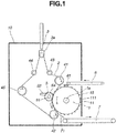
- the cutoff machining apparatus includes a work carrier 1, an elastic belt 2, a belt expanding mechanism 3, a first belt support 41, a second belt support 42, and an outer cutoff blade 5, which are enclosed in a frame/housing 10.
- the work carrier 1 is a cylindrical or columnar rotating drum mounted on a horizontal rotating spindle 1a and having a generally regular polygonal shape in a cross section perpendicular to the rotating spindle 1a. It will be understood that the proposals are applicable in general for a carrier mounted for rotation around a horizontal axis, and references to a spindle are not to be regarded as limitative in this respect although a spindle is preferably.
- the polygonal shape is a figure having at least 3 sides, preferably at least 6 sides, more preferably at least 12 sides and up to 180 sides, preferably up to 60 sides. In FIG. 1 , a columnar rotating drum of regular 24-sided polygonal shape is illustrated.
- the work carrier 1 has a peripheral surface which consists of a plurality of sides (24 sides in FIG. 1 ) corresponding to the number of edges (24 edges in FIG. 1 ) of the polygonal shape.
- surface sides 11 are defined by polygonally dividing the peripheral surface of the work carrier 1 of polygonal cross-sectional shape (regular 24-sided polygonal shape in FIG. 1 ).
- FIG. 2 is a partial elevational view of the work carrier 1 in FIG. 1 , wherein work seats 111 are formed on the respective sides 11 of the peripheral surface of the polygonal work carrier 1 and distributed around in the rotational direction of the work carrier 1. For each side 11, there may be provided only one work seat 111 or two or more work seats 111.
- the work carrier 1 shown in FIG. 2 includes forty eight (48), in total, work seats 111 in the sense that twenty four (24) work seats 111 are arranged in the rotational direction of the work carrier 1 and two rows of work seats 111 are juxtaposed in the rotating spindle direction of the work carrier 1.
- the peripheral surface of the work carrier 1 is provided, specifically within the work seats 111, with a groove 12 extending in the rotational direction of the work carrier, so that the circumferential edge of the outer cutoff blade 5 may enter the groove 12.
- the groove 12 ensures that the outer cutoff blade 5 cutoff can machine the work (workpiece) through to its bottom (i.e. the lower surface of the work facing the work carrier 1) without contacting the work carrier 1.
- the groove 12 is formed in accordance with the cutoff position and division number of the work. In the work carrier 1 shown in FIG.
- the peripheral surface of the work carrier 1 may be provided, specifically within (as distinct from between) the work seats 111, with grooves 13 extending toward opposite ends in the rotating spindle direction of the work carrier 1.
- the grooves 13 extending in the rotating spindle direction allow the coolant and chips (resulting from cutoff machining) to be discharged efficiently at the contact between the work and the work seat 111 and nearby.
- three grooves 13 extend in the rotating spindle direction of the work carrier 1. It is noted that another groove 14 may be formed between two rows of work seats 111 juxtaposed in the rotating spindle direction of the work carrier 1.
- This circumferential groove 14 functions as an opening for discharging the coolant and chips outside from the axially extending grooves 13 in the state that the work is in contact with the work carrier 1. It is acceptable that the circumferential edge of an outer cutoff blad, which is not participating in cutoff machining enters the groove 14.
- the groove 14 extends between the rows of work seats 111 arranged in the rotational direction of the work carrier 1, along the rotational direction of the work carrier 1 (i.e. circumferentially), and between juxtaposed work seats 111. That is, one groove 14 is formed between two work seats 111.
- the work carrier 1 is provided, as shown in FIG. 2 , at the edges on the peripheral surface of the polygonal work carrier 1, that is, at the junctions (24 junctions in FIG. 1 ) between sides 11 constituting the peripheral surface of the polygonal work carrier 1, with belt abutments 15 for supporting the elastic belt 2 in the absence of any work and for restraining the elastic belt 2 from any shift in the rotating spindle direction of the work carrier 1.
- the belt abutment 15 may project radially outward or upright from the edge on the peripheral surface of the work carrier 1 in a direction perpendicular to the rotating spindle of the work carrier 1.
- Each belt abutment 15 has a pair of collars or lateral restraints 151, 151 protruding like horns from the side of the abutment disposed remote from the rotating spindle (axis) of the work carrier 1 (radially outward) at the opposite ends in the rotating spindle direction of the work carrier 1.
- the pair of collars 151, 151 come in engagement with the elastic belt 2 for restraining the elastic belt 2 from any shift in the rotating spindle direction of the work carrier 1.
- the belt abutments 15 can also play the role of restraining the work from shifting forward or aft (or falling down) in the rotational direction of the work carrier 1.
- the belt abutments 15 are typically provided for each elastic belt 2.
- the work carrier 1 shown in FIG. 2 is designed such that one work is secured by two elastic belts 2.
- Two belt abutments 15 are formed for each work seat 111, namely two belt abutments 15 are formed forward and aft of the work seat 11 in the rotational direction of the work carrier 1.
- For twenty four (24) work seats 111 arranged in the rotational direction of the work carrier 1 forty eight (48) belt abutments 15 are formed. Further, since two rows of work seats 111 are juxtaposed in the rotating spindle direction of the work carrier 1, ninety six (96) belt abutments 15 are formed on the overall work carrier 1.
- the height of the belt abutments 15 is lower than the height of the work which is rested on and secured to the work seat.
- Each elastic belt 2 is an endless belt. As shown in FIG. 1 , the path of the belt 2 is extended so as to approach close to a portion of the peripheral surface of the work carrier 1, adapted to urge a work of sintered magnet against the peripheral surface of the work carrier 1 to secure the work, and adapted to move synchronously with and complementarily to the work carrier 1 in a circulatory manner.
- each elastic belt 2 is extended along the peripheral surface of the work carrier 1 on its side (the left side in FIG. 1 ) where the peripheral surface moves downward during rotation of the work carrier 1 and so as to come close to a portion of the peripheral surface of the work carrier 1 between a first belt support 41 and a second belt support 42 to be described below.
- the belt 2 is conveniently adapted to travel counter to the rotation of the work carrier in a circulatory manner.
- the work carrier 1 rotates counterclockwise and the belt 2 travels generally clockwise, counter to the rotation of the work carrier 1 in a circulatory manner.
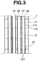
- FIG. 3 is a partial side view showing the elastic belts 2 when close to the work carrier 1.
- the belt 2 extends to bridge the belt abutments 15 arranged in the rotational direction of the work carrier 1 when no works are delivered.
- the cutoff machining apparatus is designed such that each work resting on the work seat 111 is secured thereto by at least two elastic belts 2. This means that plural (i.e. two or more) elastic belts 2 are included.
- one work is secured to the seat 111 by two elastic belts 2a, 2b.
- Two elastic belts 2a, 2b are extended in proximity to the work carrier 1 for the row of the work seats 111 arranged in the rotational direction of the work carrier 1. Since there are two rows of the work seats 111 arranged in the rotational direction of the work carrier 1, four elastic belts 2 are included on the overall work carrier 1. It is noted that for simplicity's sake, only one elastic belt 2 is shown in FIG. 1 .
- the plural elastic belts 2 for securing one work are juxtaposed at a predetermined spacing so that an outer cutoff blade 5 may be inserted through the spacing. Then the circumferential edge (abrasive cutting edge) 5a of the outer cutoff blade 5 can cutoff machine the work without contacting the belts 2. Accordingly, the spacing between the belts 2 is defined, as shown in FIGS. 2 and 3 , at a position corresponding to the groove 12 in the work carrier 1 for allowing entry of the circumferential edge 5a of the outer cutoff blade 5.
- the cutoff machining apparatus includes two or more belt supports.
- the belt supports serve to support the belt 2 in tension and to change the traveling direction or define the path of the belt 2 during its circulatory travel.
- Each belt support is preferably a roller of circular cross-sectional shape.
- the belt support contacts the belt 2 at its peripheral surface and changes the traveling direction or defines the circulation path of the belt 2 as the support rotates.
- the cutoff machining apparatus includes a first belt support disposed above the rotating spindle of the work carrier 1 and in proximity to the peripheral surface of the carrier 1 and a second belt support disposed below the rotating spindle of the carrier 1 and in proximity to the peripheral surface of the work carrier.
- first (upper) belt support 41 disposed above the rotating spindle 1a of the carrier 1 and in proximity to a portion of the peripheral surface of the carrier 1 which extends forwardly from the top of the carrier 1 (in the rotational direction of the carrier 1)
- second (lower) belt support 42 disposed below the rotating spindle 1a of the carrier 1 and in proximity to a portion of the peripheral surface of the carrier 1 which extends back from the bottom of the carrier to an aft position (in the rotational direction of the carrier 1).
- the elastic belt 2 is driven along in proximity to the peripheral surface of the work carrier 1, tensioned by the belt expanding/tensioning mechanism 3 to be described later, and supported in tension and travel path by the first and second belt supports or rollers 41 and 42.
- the traveling direction of the belt 2 is changed during their circulatory travel.
- the first belt support 41 acts to guide or change the traveling direction of the elastic belt 2 from the side (left side in FIG. 1 ) spaced apart from the peripheral surface of the carrier 1 to a direction parallel to (along) the peripheral surface of the carrier 1.
- the second belt support 42 acts to guide or change the traveling direction of the elastic belt 2 from a direction parallel to (along) the peripheral surface of the carrier 1 to the side (left side in FIG. 1 ) spaced apart from the peripheral surface of the carrier 1.
- FIG. 4 is a side elevational view showing how the elastic belt 2 is supported by the first belt support 41 in the cutoff machining apparatus of FIG. 1 .
- the first belt support 41 is provided with a pair of annular guides 41a, 41b for each of the elastic belts 2 for restraining the belt from shifting in the rotation spindle direction of the carrier 1. Then the elastic belt 2 comes in contact with the peripheral surface of the first belt support 41 between the guides 41a and 41b.
- the second belt support 42 is also provided with similar guides. Belt supports other than the first and second belt supports 41 and 42 may also be provided with annular guides.
- the belt expanding mechanism or tensioning mechanism 3 serves to tension the elastic belts 2.
- the belt expanding mechanism 3 is not particularly limited as long as it can expand the elastic belt 2 so as to create a tension force to urge the belt against the peripheral surface of the carrier 1.
- third and fourth belt supports 43 and 44 are provided for supporting in tension a portion of the belt 2 other than the portion thereof extending in proximity to the peripheral surface of the carrier 1 and changing the traveling direction of the belt 2 during its circulatory travel.
- the belt expanding mechanism 3 serves to act on the endless elastic belt 2 between the third and fourth belt supports 43 and 44 so as to pull the belt outward or push the belt inward of its track to tension the belt.
- the third and fourth belt supports 43 and 44 are pulleys.
- the belt expanding mechanism 3 also has a pulley 3a at its distal or lower end.
- the pulley 3a of the belt expanding mechanism 3 also serves to support the belt 2 in tension and change the traveling direction of the belt 2 during its circulatory travel.
- the pulley 3a is also constructed such that it may contact on its peripheral surface with the belt 2 and change the traveling direction of the belt 2 as the pulley rotates.
- the cutoff machining apparatus may further include additional belt supports.
- a fifth belt support 45 is included in FIG. 1 .
- the fifth belt support 45 is spaced apart from the work carrier 1 and positioned far away from the area where the belt expanding mechanism 3 and the third and fourth belt supports 43, 44 are installed. Additional belt supports may be provided in conjunction with the position of the belt expanding mechanism 3 and for the purpose of maintaining a space within the apparatus.
- one belt support is used to support all elastic belts 2 as shown in FIG. 4 , or plural belt supports are provided independently for one belt or some belts so that independent motion may be available for different belts, e.g. each of belts 2.
- the belt support may be an assembly of plural pulleys 411 corresponding to individual elastic belts 2.
- FIG. 6 is a side elevational view showing another embodiment wherein the elastic belts 2 are supported by the first belt support 41 in the cutoff machining apparatus of FIG. 1 . In this embodiment, four elastic belts 2 are independently supported by four pulleys 411.
- the outer cutoff blade 5 having a circumferential edge is mounted on a horizontal rotating shaft and the assembly is adapted to move toward and away from the work carrier 1. Specifically, the outer cutoff blade 5 is adapted to move toward and away from the peripheral surface of the work carrier 1 between the first and second belt supports 41 and 42.
- the position where the cutoff blade 5 approaches the peripheral surface of the carrier 1 is preferably an intermediate position between the first and second belt supports 41 and 42 so that chips may be efficiently discharged from near the cutoff blade 5.
- the cutoff blade 5 is combined with a mechanism for moving and securing the cutoff blade 5 so that the cutoff blade 5 may be moved and secured at the cutting site.
- the cutoff blade 5 is positioned such that it may pass through the spacing between the elastic belts 2 (for securing the work), and the circumferential edge of the cutoff blade 5 may reach the groove 12 formed in the seats 111 on the work carrier 1.
- the outer cutoff blade 5 When works are arranged as a single row in the rotational direction of the carrier 1 and cutoff machining is done at only one site, the outer cutoff blade 5 may be a single blade. When cutoff machining is at two or more sites or when a plurality of works are arranged in the rotating spindle direction of the carrier 1, the outer cutoff blade 5 preferably takes the form of a multiple blade assembly having a plurality of outer cutoff blades 5 mounted on a rotating shaft with a spacer interposed between the blades. In the multiple blade assembly, the number of blades is two or more and may be selected as appropriate depending on a particular sawing application.
- FIG. 7 is a cross-sectional view of the multiple blade assembly in the cutoff machining apparatus of FIG. 1 .
- the multiple blade assembly has a plurality of outer cutoff blades 5 which are mounted on a rotating shaft 51 while a spacer 511 is interposed between the blades 5.
- Each outer cutoff blade 5 has an abrasive cutting edge portion 5a on its circumferential edge. As the blade 5 is rotated, the cutting edge portion 5a acts to gradually machine the work and finally cut (or divide) it into pieces.
- 1 and 7 uses a multiple blade assembly of two, in total, outer cutoff blades 5 wherein one outer cutoff blade 5 cutoff machines one work at one site into two pieces and one outer cutoff blade 5 is assigned to each of two works arranged in the rotating spindle direction of the carrier 1.
- One spacer 511 is interposed between two outer cutoff blades 5, and the blades 5 are secured by end caps 512 mounted on opposite ends of the rotating shaft 51.
- a nozzle is provided in proximity to the outer cutoff blade 5, especially in proximity to the circumferential edge of the outer cutoff blade 5, for supplying a coolant to the cutoff site on the work by the blade 5.
- the provision of the nozzle ensures effective cooling of the cutoff site.
- a nozzle 52 is provided in proximity to the blade 5 for supplying coolant onto the circumferential edge of the blade(s) 5. Once the coolant is injected from the nozzle 52, the coolant is entrained on the blade 5 and conveyed to the cutoff site on the work in accordance with rotation of the blade 5.
- works may be sequentially delivered by manual operation.
- an inlet conveyor is provided in an area where the work is delivered onto the peripheral surface of the work carrier.
- an inlet conveyor 6 for conveying works is provided in an area where the work is delivered onto the peripheral surface of the work carrier 1.
- Works are conveyed from the outside end to the inside end of the inlet conveyor 6 where the works are delivered onto the peripheral surface of the carrier 1.
- a transfer mechanism may be provided between the inside end of the inlet conveyor 6 and the peripheral surface of the carrier 1 for transferring the work from the inlet conveyor 6 onto the peripheral surface of the carrier 1.
- a guide is preferably disposed where the work is delivered onto the peripheral surface of the carrier for placing the work in alignment with the position where the work is rested on the seat 111. More preferably the guide is of a structure capable of centering the work in accordance with rotation of the carrier 1.
- a guide 61 is disposed above the carrier 1 where the work is delivered onto the peripheral surface of the carrier 1. As best shown in FIG. 8 , the guide 61 is provided with two openings 61a whose position and size correspond to the position where the work is rested on the seat 111 and the size of the work, respectively.
- divided work i.e. cut pieces of a sintered magnet workpiece
- an outlet conveyor is provided in an area where the divided work is released from the seat, for carrying out the divided work.
- a chute is preferably provided for guiding the divided work when the divided work released from the peripheral surface of the carrier is transferred to the outlet conveyor.
- an outlet conveyor 7 for conveying works is provided in an area where the divided work is released from the seat 111.
- the divided work is conveyed from the inside end to the outside end of the outlet conveyor 7, that is, from the area where the divided work is released from the seat 111 to the outside end of the outlet conveyor 7.
- a plate-shaped chute 71 is disposed in proximity to the peripheral surface of the carrier 1 to form a bridge between the area where the divided work is released from the seat 111 and the inside end of the outlet conveyor 7. The divided work slides down the chute 71 and reaches the inside end of the outlet conveyor 7.
- FIG. 8 is a partial plan view of the work carrier 1 in the cutoff machining apparatus of FIG. 1 as viewed from above, illustrating how a work W is delivered to the seat 111 on the carrier 1.
- the work W is typically of rectangular shape, preferably plate shape.
- the work W typically has a thickness of at least 0.1 mm, especially at least 1 mm and up to 30 mm, especially up to 10 mm.
- the thickness of the work corresponds to the distance between the elastic belt and the work carrier when the work is secured to the seat on the carrier by the elastic belt.
- the work W is first conveyed by inlet conveyor 6 to its inside end near carrier 1, moved past opening 61a in guide 61, and delivered onto seat 111 on carrier 1.
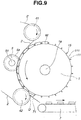
- FIG. 9 is a side view of the carrier in the cutoff machining apparatus of FIG. 1 , showing that work W rested on seat 111 of carrier 1 is secured to seat 111 by elastic belt 2, carried forward (downward), cutoff machined by outer cutoff blade 5, and discharged below carrier 1.
- work W is delivered onto the peripheral surface (specifically seat 111) of work carrier 1 from an aft position in the rotational direction of carrier 1 with respect to first belt support 41, it is carried forward with rotation of carrier 1 (rotation of carrier 1 may be continuous or intermittent), moved past first belt support 41, and secured or clamped between carrier 1 and belt 2 by the pressing force of belt 2 in the range between first and second belt supports 41 and 42.
- the work W clamped between carrier 1 and elastic belt 2 is advanced (moved forward or downward) in accordance with the rotation of the carrier 1.
- the work W comes in contact with outer cutoff blade 5 which is held at a cutting position inserted through the spacing between adjacent belts 2 (for securing work W) and extending onto the peripheral surface of carrier 1, specifically the outer edge (abrasive cutting edge) 5a of the outer cutoff blade 5 being inserted into the groove 12 in the peripheral surface (seat 111) of the carrier 1.
- the work W in the secured state is cutoff machined by the outer cutoff blade 5.
- FIG. 10 is a partial side view for describing the machining action of the cutoff machining apparatus of FIG. 1 , showing work W, carrier 1, elastic belts 2 and outer cutoff blades 5. Each work W was held by two belts 2, so after cutting each piece D is still secured on the carrier by a belt 2.
- the divided work (pieces) D still secured between carrier 1 and belt 2 are moved forward with rotation of carrier 1, after which belt 2 is separated from the divided work D in proximity to second belt support 42.
- the divided work D is released from the attachment by belt 2 and discharged at a forward position in the rotational direction of carrier 1 with respect to second belt support 42.
- the divided work D as discharged is released (falls down) from the peripheral surface (i.e. seat 111) of carrier 1 and transferred to chute 71.
- the divided work D slides down chute 71 under its own weight and reaches outlet conveyor 7. Thereafter divided work D is conveyed by outlet conveyor 7 from its inside end to its outside end.
- the cutoff machining apparatus and method of the invention are designed such that the steps of delivering a work onto the peripheral surface of a work carrier, clamping the work between the carrier and an elastic belt and securing it to a seat on the carrier, moving the work forward, cutoff machining the secured work by an outer cutoff blade which is disposed forward in the moving direction, and detaching and discharging the divided work are continuously carried out in a serial flow in accordance with rotation of the carrier.
- the cutoff machining apparatus and method eliminate a need for attachment and detachment of sintered magnet to and from a jig and a need for mounting and dismounting of the jig to and from a sawing machine, as required in the prior art, and are successful in cutoff machining a sintered magnet at a high productivity and high accuracy while reducing the standby time of the apparatus.
Landscapes
- Engineering & Computer Science (AREA)
- Mechanical Engineering (AREA)
- Mining & Mineral Resources (AREA)
- Finish Polishing, Edge Sharpening, And Grinding By Specific Grinding Devices (AREA)
- Processing Of Stones Or Stones Resemblance Materials (AREA)
- Constituent Portions Of Griding Lathes, Driving, Sensing And Control (AREA)
- Grinding Of Cylindrical And Plane Surfaces (AREA)
Claims (15)
- Appareil d'usinage destiné à la découpe d'aimants frittés, comprenant :un porte-pièce cylindrique ou colonnaire (1) monté sur un axe de rotation horizontal tel qu'une tige de rotation et ayant une forme généralement polygonale régulière dans une section transversale perpendiculaire à l'axe de rotation, à la condition que le polygone ait 3 à 180 côtés,une pluralité de courroies élastiques sans fin (2) qui sont étendues de sorte à se rapprocher d'une partie d'une surface périphérique du porte-pièce, adaptées pour pousser une pièce (W) d'aimant fritté contre la surface périphérique du porte-pièce pour immobiliser la pièce, et adaptées pour se déplacer de manière synchrone avec la rotation du porte-pièce d'une manière circulatoire,un mécanisme d'extension de courroie (3) destiné à tendre les courroies (2),au moins deux supports de courroie (41-45) pour supporter les courroies (2) sous tension et adaptés pour définir la direction de déplacement des courroies au cours de leur déplacement circulatoire,une lame de coupe externe (5) ayant un bord circonférentiel (5a), montée sur un arbre rotatif horizontal (51) et adaptée pour être positionnée de telle sorte que le bord circonférentiel soit proche de la surface périphérique du porte-pièce, etdes sièges de pièce (111) formés sur les côtés respectifs de la surface périphérique du porte-pièce polygonal (1) et agencés dans le sens de rotation du porte-pièce,la pluralité de courroies élastiques (2) étant étendues de telle sorte que la pièce (W) reposant sur chaque siège de pièce (111) est immobilisée sur celui-ci par au moins deux courroies élastiques qui sont juxtaposées selon un espacement,les au moins deux supports de courroie incluant un premier support de courroie (41) disposé au-dessus de l'axe de rotation du porte-pièce (1) et à proximité d'une partie de la surface périphérique du porte-pièce qui s'étend de la partie supérieure du porte-pièce à une position avant dans le sens de rotation du porte-pièce, et un deuxième support de courroie (42) disposé en dessous de l'axe de rotation du porte-pièce et à proximité d'une partie de la surface périphérique du porte-pièce qui s'étend de la partie inférieure du porte-pièce à une position arrière dans le sens de rotation du porte-pièce,l'appareil étant opérationnel de telle sorte qu'en utilisation, la pièce (W) est distribuée sur la surface périphérique du porte-pièce avant le premier support de courroie (41), par rapport au sens de rotation du porte-pièce, et immobilisée sur le siège par les courroies élastiques (2) entre les premier et deuxième supports de courroies (41, 42) en fonction de la rotation du porte-pièce,la pièce est avancée en fonction de la rotation du porte-pièce et découpée par ladite lame de coupe externe (5) insérée entre les au moins deux courroies élastiques (2),la pièce divisée résultante est en outre avancée en fonction de la rotation du porte-pièce, libérée du siège, et déchargée du porte-pièce au niveau d'une position après le deuxième support de courroie (42), par rapport au sens de rotation du porte-pièce.
- Appareil d'usinage selon la revendication 1 comprenant une buse (52) destinée à fournir un liquide de refroidissement sur le site où la pièce est découpée par la lame de coupe externe (5).
- Appareil d'usinage selon la revendication 1 ou 2, dans lequel chacun des sièges de pièce (111) sur les côtés respectifs de la surface périphérique du porte-pièce polygonal est divisé en une pluralité de segments de siège dans le sens de l'axe de rotation du porte-pièce.
- Appareil d'usinage selon l'une quelconque des revendications 1 à 3, dans lequel la lame de coupe externe prend la forme d'un ensemble de lames multiples ayant une pluralité de lames de coupe externes montées sur l'arbre rotatif avec un élément d'espacement interposé entre les lames.
- Appareil d'usinage selon l'une quelconque des revendications 1 à 4, dans lequel la surface périphérique du porte-pièce est dotée d'une rainure (12) dans le sens de rotation du porte-pièce, destinée à recevoir le bord circonférentiel (5a) de la lame de coupe externe.
- Appareil d'usinage selon l'une quelconque des revendications 1 à 5, dans lequel les sièges de pièce (111) sont dotés de rainures (13) s'étendant entre leurs extrémités opposées dans le sens de l'axe de rotation du porte-pièce.
- Appareil d'usinage selon l'une quelconque des revendications 1 à 6, dans lequel sont formées des butées de courroies (15), alignées avec chaque courroie (2), au niveau des bords entre lesdits côtés de la surface périphérique du porte-pièce polygonal, pour empêcher la courroie (2) de se déplacer dans le sens de l'axe de rotation du porte-pièce.
- Appareil d'usinage selon la revendication 7, dans lequel les butées de courroie (15) font saillie radialement vers l'extérieur à partir desdits bords sur le porte-pièce.
- Appareil d'usinage selon l'une quelconque des revendications 1 à 8, dans lequel les au moins deux supports de courroie incluent en outre des troisième et quatrième supports de courroie qui sont disposés à l'extérieur de la région où les courroies (2) se rapprochent de la surface périphérique du porte-pièce, afin de maintenir les courroies sous tension tout en définissant la trajectoire des courroies pour leur déplacement circulatoire.
- Appareil d'usinage selon l'une quelconque des revendications précédentes, dans lequel le mécanisme d'extension de courroie (3) se met en prise avec les courroies et peut être utilisé pour tirer vers l'extérieur sur les courroies et régler leur trajectoire vers l'extérieur ou vers l'intérieur, par exemple entre les troisième et quatrième supports de courroie selon la revendication 9.
- Appareil d'usinage selon l'une quelconque des revendications 1 à 10, comprenant un transporteur d'entrée (6) disposé près d'une région où la pièce est distribuée sur la surface périphérique du porte-pièce, destiné à transporter la pièce vers ladite région.
- Appareil d'usinage selon l'une quelconque des revendications 1 à 11, comprenant un guide (61) disposé au niveau de la région où la pièce est distribuée sur la surface périphérique du porte-pièce, destiné à guider chaque pièce en place sur un dit siège de pièce (111).
- Appareil d'usinage selon l'une quelconque des revendications 1 à 12, comprenant un transporteur de sortie (7) disposé près de la région où la pièce divisée est déchargée du siège sur le porte-pièce, destiné à transporter la pièce divisée hors de la zone.
- Procédé d'usinage de pièces de fabrication (W) d'aimants frittés par découpe des pièces de fabrication en pièces divisées (D), comprenant(a) la fourniture d'un appareil d'usinage comprenant :un porte-pièce rotatif (1) ayant des sièges de pièce (111) répartis autour de sa surface périphérique pour recevoir les pièces de fabrication respectives ;un ensemble lame comprenant une lame de coupe rotative (5) ayant un bord circonférentiel et positionné de manière adjacente à la surface périphérique du porte-pièce pour couper des pièces de fabrication sur celle-ci au niveau d'une position de coupe, etdes moyens pour maintenir les pièces de fabrication contre la surface périphérique du porte-pièce (1) pour ladite coupe, comprenant des courroies élastiques (2) adaptées pour circuler de manière synchrone avec la rotation du porte-pièce, au moins deux supports de courroie (41-45) destinés à supporter les courroies sous tension et définir la trajectoire circulatoire des courroies, et un mécanisme de tension de courroie destiné à tendre les courroies, lesdits supports de courroie incluant un premier support de courroie (41) et un deuxième support de courroie (42) disposé à proximité de la surface périphérique du porte-pièce (1) de sorte à pousser les courroies tendues circulantes passant entre eux contre une région correspondante de la surface périphérique du porte-pièce rotatif qui inclut la position de coupe ;(b) la fourniture des pièces de fabrication (W) dans lesdits sièges de pièce (111) respectifs sur la surface périphérique du porte-pièce rotatif, avant ladite région où les courroies sont poussées contre le porte-pièce ;
l'immobilisation des pièces de fabrication (W) dans leurs sièges par les courroies (2) étant poussées contre les pièces de fabrication lorsqu'elles avancent vers ladite région où les courroies sont poussées contre le porte-pièce ;
la coupe à travers les pièces de fabrication (W) pour former des pièces divisées (D) au moyen de la lame de coupe rotative (5) lorsque les pièces de fabrication avancent devant la position de coupe, la lame étant insérée entre les courroies (2) adjacentes, moyennant quoi les pièces divisées (D) sont maintenues en place par les courroies après la coupe, et
le déchargement des pièces divisées du porte-pièce après qu'elles ont avancé devant la région où les courroies sont poussées contre le porte-pièce. - Procédé selon la revendication 14, réalisé par un appareil ayant les caractéristiques telles que définies dans l'une quelconque des revendications 1 à 13.
Applications Claiming Priority (1)
| Application Number | Priority Date | Filing Date | Title |
|---|---|---|---|
| JP2017104336A JP6772959B2 (ja) | 2017-05-26 | 2017-05-26 | 焼結磁石の切断加工機及び切断加工方法 |
Publications (2)
| Publication Number | Publication Date |
|---|---|
| EP3406380A1 EP3406380A1 (fr) | 2018-11-28 |
| EP3406380B1 true EP3406380B1 (fr) | 2020-12-23 |
Family
ID=62200324
Family Applications (1)
| Application Number | Title | Priority Date | Filing Date |
|---|---|---|---|
| EP18173038.3A Active EP3406380B1 (fr) | 2017-05-26 | 2018-05-17 | Appareil et procédé d'usinage pour la coupe d'aimants frittés |
Country Status (7)
| Country | Link |
|---|---|
| US (2) | US11185958B2 (fr) |
| EP (1) | EP3406380B1 (fr) |
| JP (1) | JP6772959B2 (fr) |
| CN (2) | CN114700875A (fr) |
| MY (1) | MY191928A (fr) |
| PH (1) | PH12018000143A1 (fr) |
| SG (1) | SG10201804339UA (fr) |
Families Citing this family (6)
| Publication number | Priority date | Publication date | Assignee | Title |
|---|---|---|---|---|
| US11548188B1 (en) * | 2018-08-27 | 2023-01-10 | Yonani Industries Ltd. | Veneer stone saw with rotary feed |
| CN110466991A (zh) * | 2019-07-01 | 2019-11-19 | 章凌霞 | 一种管件连续转运导料机构 |
| CN111283495A (zh) * | 2020-02-18 | 2020-06-16 | 赵雪勇 | 一种钢材切割、打磨、除尘一体化设备 |
| CN111716571B (zh) * | 2020-07-01 | 2021-08-13 | 山东嘉和耐火材料有限责任公司 | 一种耐火材料加工用的切割装置 |
| CN114289639A (zh) * | 2021-12-23 | 2022-04-08 | 陈世旺 | 一种建筑施工用钢筋截断装置 |
| CN114523150B (zh) * | 2022-04-24 | 2022-07-05 | 宁波招宝磁业有限公司 | 一种拼接磁钢自动加工设备及加工方法 |
Citations (1)
| Publication number | Priority date | Publication date | Assignee | Title |
|---|---|---|---|---|
| JP2001047363A (ja) * | 1999-06-01 | 2001-02-20 | Sumitomo Special Metals Co Ltd | 磁石部材切断方法および磁石部材切断装置 |
Family Cites Families (20)
| Publication number | Priority date | Publication date | Assignee | Title |
|---|---|---|---|---|
| CH175598A (de) * | 1934-07-11 | 1935-03-15 | Meuli Schmidweber & Co | Maschine zum Schneiden von Platten, insbesondere Steinplatten. |
| US2553136A (en) * | 1950-01-18 | 1951-05-15 | Eisler Charles | High-speed tube or cane crack-off machine |
| US3067644A (en) * | 1958-04-22 | 1962-12-11 | American Mach & Foundry | Mouthpiece feed |
| US3122043A (en) * | 1960-01-19 | 1964-02-25 | Shanok Victor | Rotary saw with rotary work conveyor |
| CH432806A (de) * | 1965-03-08 | 1967-03-31 | Bauwerk Bodenbelagsind Ag | Maschine zum Abtrennen von Rohfries-Abschnitten zur Herstellung von Parkettleisten |
| US3797338A (en) * | 1972-04-07 | 1974-03-19 | M Molnar | Machine for mass production of both medium and short lengths of tubing |
| DE2232960A1 (de) * | 1972-07-05 | 1974-01-17 | Hauni Werke Koerber & Co Kg | Vorrichtung zum queraxialen, achsparallelen foerdern von stabfoermigen artikeln der tabakverarbeitenden industrie auf einer gekruemmten bahn |
| NL7901893A (nl) * | 1979-03-08 | 1980-09-10 | Mattijssen Bv Maschf | Stenenzaagmachine. |
| IT1251507B (it) * | 1991-05-24 | 1995-05-16 | Franco Andreucci | Tamburo orizzontale per la presa e la traslazione della legna alla macchina segatrice |
| MY163878A (en) | 2008-11-05 | 2017-11-15 | Shinetsu Chemical Co | Method and apparatus for multiple cutoff machining of rare earth block, cutting fluid feed nozzle, and magnet block securing jig |
| JP2010110850A (ja) | 2008-11-05 | 2010-05-20 | Shin-Etsu Chemical Co Ltd | 研削液供給ノズル及びこれを備える希土類磁石切断加工装置 |
| JP5228811B2 (ja) | 2008-11-05 | 2013-07-03 | 信越化学工業株式会社 | 磁石固定治具及びこれを備える希土類磁石切断加工装置 |
| JP5481837B2 (ja) | 2008-11-05 | 2014-04-23 | 信越化学工業株式会社 | 希土類磁石のマルチ切断加工方法 |
| JP5139364B2 (ja) | 2009-04-22 | 2013-02-06 | 本田鐵工株式会社 | 切断機 |
| CN101703313B (zh) * | 2009-11-13 | 2011-10-19 | 国营红阳机械厂 | 一种滤棒分切输送装置 |
| MY157471A (en) | 2010-01-06 | 2016-06-15 | Shinetsu Chemical Co | Rare earth magnet holding jig, cutting machine and cutting method |
| MY155758A (en) | 2010-01-06 | 2015-11-30 | Shinetsu Chemical Co | Rare earth magnet holding jig and cutting machine |
| JP5505114B2 (ja) * | 2010-06-16 | 2014-05-28 | 信越化学工業株式会社 | 希土類焼結磁石のマルチ切断加工方法 |
| DE102015002798A1 (de) | 2015-03-06 | 2016-09-08 | Focke & Co. (Gmbh & Co. Kg) | Vorrichtung zum Transport von Gegenständen, insbesondere Packungen |
| JP6500864B2 (ja) | 2015-09-30 | 2019-04-17 | 信越化学工業株式会社 | 焼結磁石の連続切断装置 |
-
2017
- 2017-05-26 JP JP2017104336A patent/JP6772959B2/ja active Active
-
2018
- 2018-05-15 US US15/980,013 patent/US11185958B2/en active Active
- 2018-05-15 MY MYPI2018701849A patent/MY191928A/en unknown
- 2018-05-17 EP EP18173038.3A patent/EP3406380B1/fr active Active
- 2018-05-22 SG SG10201804339UA patent/SG10201804339UA/en unknown
- 2018-05-23 PH PH12018000143A patent/PH12018000143A1/en unknown
- 2018-05-25 CN CN202210461405.XA patent/CN114700875A/zh active Pending
- 2018-05-25 CN CN201810512519.6A patent/CN108942644B/zh active Active
-
2021
- 2021-10-26 US US17/510,756 patent/US11701748B2/en active Active
Patent Citations (1)
| Publication number | Priority date | Publication date | Assignee | Title |
|---|---|---|---|---|
| JP2001047363A (ja) * | 1999-06-01 | 2001-02-20 | Sumitomo Special Metals Co Ltd | 磁石部材切断方法および磁石部材切断装置 |
Also Published As
| Publication number | Publication date |
|---|---|
| US20220063049A1 (en) | 2022-03-03 |
| MY191928A (en) | 2022-07-18 |
| US11185958B2 (en) | 2021-11-30 |
| SG10201804339UA (en) | 2018-12-28 |
| CN114700875A (zh) | 2022-07-05 |
| US20180339391A1 (en) | 2018-11-29 |
| CN108942644A (zh) | 2018-12-07 |
| JP2018199177A (ja) | 2018-12-20 |
| JP6772959B2 (ja) | 2020-10-21 |
| CN108942644B (zh) | 2022-05-10 |
| PH12018000143A1 (en) | 2019-10-28 |
| EP3406380A1 (fr) | 2018-11-28 |
| US11701748B2 (en) | 2023-07-18 |
Similar Documents
| Publication | Publication Date | Title |
|---|---|---|
| EP3406380B1 (fr) | Appareil et procédé d'usinage pour la coupe d'aimants frittés | |
| JP6378418B2 (ja) | 工作物を回転させるための回転ユニットを備える装置、及び加工装置 | |
| JP2001121389A (ja) | バリ取り装置 | |
| CN114800080B (zh) | 一种打磨装置 | |
| KR101999505B1 (ko) | 파이프의 버(burr) 제거장치 | |
| US10427219B2 (en) | Apparatus for continuously cutoff machining sintered magnet blocks | |
| JP4398160B2 (ja) | 無端状金属ベルト用金属リングの加工方法及び加工装置 | |
| US20140246006A1 (en) | Gemstone processing | |
| JP4652109B2 (ja) | 連続作業可能な円筒研削盤 | |
| KR101522008B1 (ko) | 자동차 시동장치의 피니언기어유닛에 대한 자동 연마장치 | |
| KR20170049411A (ko) | 고정 연마입자 와이어소우 및 고정 연마입자 와이어의 드레싱 방법 | |
| CN210550384U (zh) | 一种磁钢输送装置及磨削装置 | |
| KR102458268B1 (ko) | 휠 베어링 조립체의 외륜체 자동 가공시스템 | |
| CN110589429B (zh) | 对齐软管的输送装置及对齐软管的方法 | |
| KR101558515B1 (ko) | 코일 포장용 측판 제조장치와 이를 이용한 측판 제조 방법 | |
| JPH0947949A (ja) | 加工バリ研掃装置 | |
| JP2006150684A (ja) | シート状部材の成形方法及びその装置 | |
| RU2322346C1 (ru) | Способ разрезания композиционных изделий кольцевой формы | |
| JP5846001B2 (ja) | 研削装置 | |
| KR20140049078A (ko) | 와이어 소 | |
| JP2014188650A (ja) | ワイヤソー及びワイヤソーを用いた加工方法 | |
| CN105215811A (zh) | 一种u型螺栓用自动双头磨角机 | |
| JP2646231B2 (ja) | 半導体材料からのウエーハ切り出し加工方法およびその装置 | |
| JP2008307608A (ja) | センタレス研削装置 | |
| JPH02171632A (ja) | タイヤユニフオミテイーマシンに於けるリムの段取り替え方法及びその装置 |
Legal Events
| Date | Code | Title | Description |
|---|---|---|---|
| PUAI | Public reference made under article 153(3) epc to a published international application that has entered the european phase |
Free format text: ORIGINAL CODE: 0009012 |
|
| STAA | Information on the status of an ep patent application or granted ep patent |
Free format text: STATUS: THE APPLICATION HAS BEEN PUBLISHED |
|
| AK | Designated contracting states |
Kind code of ref document: A1 Designated state(s): AL AT BE BG CH CY CZ DE DK EE ES FI FR GB GR HR HU IE IS IT LI LT LU LV MC MK MT NL NO PL PT RO RS SE SI SK SM TR |
|
| AX | Request for extension of the european patent |
Extension state: BA ME |
|
| STAA | Information on the status of an ep patent application or granted ep patent |
Free format text: STATUS: REQUEST FOR EXAMINATION WAS MADE |
|
| 17P | Request for examination filed |
Effective date: 20190524 |
|
| RBV | Designated contracting states (corrected) |
Designated state(s): AL AT BE BG CH CY CZ DE DK EE ES FI FR GB GR HR HU IE IS IT LI LT LU LV MC MK MT NL NO PL PT RO RS SE SI SK SM TR |
|
| GRAP | Despatch of communication of intention to grant a patent |
Free format text: ORIGINAL CODE: EPIDOSNIGR1 |
|
| STAA | Information on the status of an ep patent application or granted ep patent |
Free format text: STATUS: GRANT OF PATENT IS INTENDED |
|
| INTG | Intention to grant announced |
Effective date: 20200210 |
|
| RIN1 | Information on inventor provided before grant (corrected) |
Inventor name: UENO, TAKAFUMI Inventor name: INAMI, HITOSHI Inventor name: KASASHIMA, MASAKI Inventor name: AKADA, KAZUHITO |
|
| GRAJ | Information related to disapproval of communication of intention to grant by the applicant or resumption of examination proceedings by the epo deleted |
Free format text: ORIGINAL CODE: EPIDOSDIGR1 |
|
| STAA | Information on the status of an ep patent application or granted ep patent |
Free format text: STATUS: REQUEST FOR EXAMINATION WAS MADE |
|
| INTC | Intention to grant announced (deleted) | ||
| GRAP | Despatch of communication of intention to grant a patent |
Free format text: ORIGINAL CODE: EPIDOSNIGR1 |
|
| STAA | Information on the status of an ep patent application or granted ep patent |
Free format text: STATUS: GRANT OF PATENT IS INTENDED |
|
| INTG | Intention to grant announced |
Effective date: 20200715 |
|
| GRAS | Grant fee paid |
Free format text: ORIGINAL CODE: EPIDOSNIGR3 |
|
| GRAA | (expected) grant |
Free format text: ORIGINAL CODE: 0009210 |
|
| STAA | Information on the status of an ep patent application or granted ep patent |
Free format text: STATUS: THE PATENT HAS BEEN GRANTED |
|
| RBV | Designated contracting states (corrected) |
Designated state(s): DE |
|
| AK | Designated contracting states |
Kind code of ref document: B1 Designated state(s): DE |
|
| REG | Reference to a national code |
Ref country code: DE Ref legal event code: R096 Ref document number: 602018010993 Country of ref document: DE |
|
| REG | Reference to a national code |
Ref country code: DE Ref legal event code: R097 Ref document number: 602018010993 Country of ref document: DE |
|
| PLBE | No opposition filed within time limit |
Free format text: ORIGINAL CODE: 0009261 |
|
| STAA | Information on the status of an ep patent application or granted ep patent |
Free format text: STATUS: NO OPPOSITION FILED WITHIN TIME LIMIT |
|
| 26N | No opposition filed |
Effective date: 20210924 |
|
| PGFP | Annual fee paid to national office [announced via postgrant information from national office to epo] |
Ref country code: DE Payment date: 20250521 Year of fee payment: 8 |