EP3406400A1 - Procédé et affûteuse destinée à l'affûtage des couteaux - Google Patents
Procédé et affûteuse destinée à l'affûtage des couteaux Download PDFInfo
- Publication number
- EP3406400A1 EP3406400A1 EP18171118.5A EP18171118A EP3406400A1 EP 3406400 A1 EP3406400 A1 EP 3406400A1 EP 18171118 A EP18171118 A EP 18171118A EP 3406400 A1 EP3406400 A1 EP 3406400A1
- Authority
- EP
- European Patent Office
- Prior art keywords
- blade
- grinding
- rounded
- cutting edge
- blade tip
- Prior art date
- Legal status (The legal status is an assumption and is not a legal conclusion. Google has not performed a legal analysis and makes no representation as to the accuracy of the status listed.)
- Granted
Links
Images



Classifications
-
- B—PERFORMING OPERATIONS; TRANSPORTING
- B24—GRINDING; POLISHING
- B24B—MACHINES, DEVICES, OR PROCESSES FOR GRINDING OR POLISHING; DRESSING OR CONDITIONING OF ABRADING SURFACES; FEEDING OF GRINDING, POLISHING, OR LAPPING AGENTS
- B24B3/00—Sharpening cutting edges, e.g. of tools; Accessories therefor, e.g. for holding the tools
- B24B3/36—Sharpening cutting edges, e.g. of tools; Accessories therefor, e.g. for holding the tools of cutting blades
- B24B3/54—Sharpening cutting edges, e.g. of tools; Accessories therefor, e.g. for holding the tools of cutting blades of hand or table knives
-
- B—PERFORMING OPERATIONS; TRANSPORTING
- B26—HAND CUTTING TOOLS; CUTTING; SEVERING
- B26B—HAND-HELD CUTTING TOOLS NOT OTHERWISE PROVIDED FOR
- B26B9/00—Blades for hand knives
Definitions
- the invention relates to a method for grinding knives.
- the invention further relates to a grinding machine for grinding knives.
- the invention also relates to a knife.
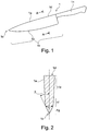
- FIG. 1 shows a known knife comprising a blade with a cutting edge, a blade back and a pointed blade tip, the blade runs along the blade blade to the blade tip.
- This knife has an increased risk of injury.
- the knife on slaughter and disassembly of animals adverse properties.
- the object of the invention is to provide a method and a device for knife grinding, which are suitable for a more advantageous knife, in particular a more advantageous slaughter knife.
- the object is in particular achieved by a method for grinding a blade blade of a knife with a rotating grinding wheel, wherein the grinding wheel comprises a frontally and / or laterally arranged, circumferentially extending grinding surface, wherein the grinding surface has a circumferentially extending, rounded recess, and wherein the blade blade includes a blade, a blade spine and a blade tip by first supplying a first side of the blade and then a second side of the blade at a feeding angle, preferably the grinding angle, to the rounded recess of the abrasive surface such that the blade tip is at least partially present for the time being abuts the rounded recess of the grinding surface, and that either the blade tip through the rounded depression to a rounded blade tip having a cutting edge is ground, or that in an already existing n, rounded blade tip through the rounded recess the edge is ground so that at least the entire rounded blade tip has a continuous edge.
- a grinding machine for grinding a blade blade of a knife comprising a grinding disk rotatable about a rotation axis with a frontally and / or laterally arranged, circumferentially extending grinding surface, wherein the grinding surface has a circumferentially extending, rounded recess, and comprising a knife guide comprising a knife guide means, the knife guide means being configured and arranged to guide the blade blade so that a blade tip of the blade blade contacts the abrasive surface substantially at a grinding angle, thereby causing the blade tip to lie in the rounded recess of the abrasive surface To produce blade tip with a continuous edge with grinding angle.
- the method according to the invention or the sharpening grinding machine according to the invention make it possible to produce a knife comprising a blade with a cutting edge, a blade back and a rounded blade tip, wherein the rounded blade tip has a cutting edge running continuously along the entire rounded blade tip.
- the blade back adjoining the rounded blade tip, starting from the rounded blade tip also has a cutting edge along a blade back portion.
- the knife according to the invention does not have a pointed knife point but a rounded knife tip, which reduces the risk of injury.
- the rounded knife tip is also sanded and provided with a cutting edge, so that it can be cut with the rounded blade tip.
- the blade back adjoining the rounded blade tip, starting from the rounded blade tip also has a cutting edge along a blade back section, so that this knife is particularly well suited for cutting, in particular as a butcher knife.
- the cutting edge at the blade tip advantageously has a grinding angle in the range between 10 ° and 30 °.
- the rounded blade tip advantageously has a radius of curvature in the range between 1 mm and 4 mm, and preferably about 2 mm.
- the cutting edge at the blade rear part section preferably has a length in the range of 5 mm to 10 mm.
- Fig. 1 shows a known knife 1 comprising a blade blade 1a.
- the blade blade 1a comprises on one side a cutting edge 1b and on the opposite side a blade back 1d.
- the cutting edge 1b and the blade back 1d meet at a pointed blade tip 1c.
- the cutting edge 1b extends along the entire blade length 1k.
- the knife 1 also includes a handle 1n.
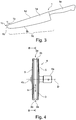
- FIG. 2 shows a cross section through the blade blade 1a along the cutting plane AA.
- the blade blade 1a comprises the blade 1b, the blade spine 1d, and therebetween the cutting bevel 1g, the major bevel 1f, and the blade mirror 1e.
- the cutting bevel 1g has a grinding angle ⁇ and a cutting angle ⁇ .
- Fig. 3 shows a side view of a knife produced by the inventive method or with the inventive grinding machine 1.
- the knife shown has the knife according to FIG. 3 a rounded blade tip 1c, wherein the rounded blade tip 1c also has a cutting edge 1b, so that the knife 1, in addition to the main cutting edge 1k, also has a cutting edge 1b running continuously along the entire rounded blade tip 1c.
- a blade back section is particularly advantageously provided with a blade 1b on the blade back 1d, the blade back section 1i directly adjoining the rounded blade tip 1c, so that the main blade 1k, the rounded blade tip 1c and the blade back section 1i form a continuous blade 1b.
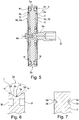
- FIG. 4 shows a front view of a rotatably mounted about a rotation axis D grinding wheel 4 comprising a grinding wheel 3, and comprising two abrasives 5, which are arranged on both sides of the grinding wheel 3.
- the grinding wheel 3 comprises a grinding surface 3a extending in the circumferential direction U, wherein the grinding surface 3a has a rounded recess 3b, wherein the recess 3b preferably has a symmetrical design with respect to a cutting plane BB running through the middle is.
- the grinding wheel 4 is fixed to the drive shaft 4a with a fixing screw 4b.
- FIG. 5 shows a longitudinal section through the grinding wheel 4 according FIG. 4 ,
- the longitudinal section extends through the axis of rotation D.
- the grinding wheel 3 comprises on both sides a groove 3f extending in the circumferential direction U, in which an elastic O-ring 4c is arranged.
- the abrasive 5 or its abrasive layer 5a is supported relative to the grinding wheel 3 in the direction of the axis of rotation D.
- the abrasive layer 5g forms a side face 3k, at which in particular the main cutting edge 1k of the knife 1 can be ground.
- the grinding wheel 3 forms the side surfaces 3k on both sides for grinding in particular the main cutting edge 1k.
- FIG. 6 shows a detail of in FIG. 5
- the grinding surface 3a has a rounded recess 3b.
- the grinding surface 3a comprises a first, rectilinear side grinding surface 3d, a rounded grinding surface 3b and a second, rectilinear side grinding surface 3e.
- in the middle of the grinding surface 3a is a recess center 3c.
- the two side grinding surfaces 3d, 3e define an angle ⁇ , which has an amount of 105 ° in the illustrated embodiment. Suitable values for the angle ⁇ are in a range between 60 ° and 160 °, so that the rounded recess 3b can enclose an angle ⁇ in the range between 60 ° and 160 °.
- the grinding surface 3a preferably has a curvature with a constant radius R in the region of the recess center 3c on, wherein the radius R is preferably in a range between 2 and 10 mm.
- the rounded recess 3b in an advantageous embodiment, the in FIG. 6 shown course by each subsequent to the region of the recess center 3c, which has the radius of curvature R, on each side followed by a rectilinear side grinding surfaces 3d, 3e.
- the side grinding surfaces 3d, 3e could also be designed to extend only partially in a straight line, or could be designed to extend in a curved manner.
- the two side grinding surfaces 3d, 3e mutually mirror-image and otherwise identical with respect to a plane perpendicular to the axis of rotation D level.
- the two side grinding surfaces 3d, 3e can also run mutually differently, individually designed.
- FIG. 7 shows a further embodiment of a grinding wheel 3, which has on both sides of the side surface each extending in the circumferential direction U grinding surface 3a, which comprises a rounded recess 3b.
- the grinding surfaces 3b can in a preferred embodiment as in FIG. 6 illustrated and described be designed extending.
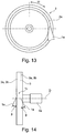
- FIG. 13 shows a side view of the in FIG. 7 shown grinding wheel.
- the grinding wheel 3 is made of a metal disk, preferably a steel disk or an aluminum disk, and the surface of the metal disk, at least the grinding surface 3a coated with an abrasive, for example borozon, a cubic form of boron nitride (cBN).
- an abrasive for example borozon, a cubic form of boron nitride (cBN).
- the rounded recess 3b preferably has a radius of curvature in the range of 1 to 4 mm, particularly advantageously about 2 mm.
- FIG. 8 shows a front view of a first embodiment of a grinding machine 2.
- the grinding machine 2 comprises a base plate 6 and a housing 7, on which a grinding wheel 4, comprising a grinding wheel 3 and abrasive 5, is rotatably mounted about a rotation axis D.
- the grinding wheel 3 comprises a grinding surface 3a with a rounded recess 3b, the grinding surface 3a being fed with a blade 1a in such a manner that the blade tip 1c comes to rest in the rounded recess 3b, and the blade tip 1c corresponding to the rounded shape of the recess 3b round shape is ground.
- the blade blade 1a in the in FIG. 8 The grinding machine 2 shown is manually supplied to the grinding surface 3a and guided in such a way that a cutting edge 1b is produced at the rounded blade tip 1c, or a cutting edge 1b already present at the blade tip 1c is ground.
- FIG. 9 shows a detailed view of the grinding machine 2 according to FIG. 8 , wherein the grinding machine 2 additionally comprises a knife guide 9, in which a knife 1 is guided.
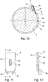
- FIG. 11 shows a plan view of a knife guide 9 comprising a support member 9a with a guide surface 9b, comprising a Verstellschlitz 9c for moving the knife guide 9 in the direction of the adjustment slot 9c, and comprising a first lateral guide member 9d and a second lateral guide member 9e.
- FIG. 12 shows the knife guide 9 in a section along the section line CC.
- FIG. 9 the blade blade 1 a is shown in contact with the grinding surface 3 a of the grinding wheel 3, wherein the blade blade 1 a rests against the guide surface 9 b via the blade mirror 1 e, and the blade blade 1 a abuts the first lateral guide member 9 d via the blade back 1 d. so that the blade 1 or the blade blade 1a is precisely guided by the blade guide 9.
- FIG. 10 shows a cut through FIG. 9 along the section line GG.
- the blade guide 9 or its guide surface 9b is arranged in such a way that the blade blade 1a comes into contact with the grinding surface 3a at the blade tip 1c at the grinding angle .beta., so that a blade 1b having a grinding angle .beta. is ground in the region of the blade tip 1c ,
- the knife guide 9 can, depending on the respective requirements, at least in the direction of movement E back and forth. How out FIG.
- the blade blade 1a is also guided over the first lateral guide part 9d in such a way that the blade tip 1c bears on the one hand against the rounded recess 3b of the grinding surface 3a, so that in the course direction of the blade tip 1c the cutting bevel 1g is ground at the grinding angle ⁇ , and on the other hand the Blade back portion 1i is applied to the first side grinding surface 3d, so that the blade back portion 1i is ground so that the first side of the blade blade 1a is ground.
- the blade blade 1a is turned to the second side, the The second side blade mirror 1e is applied to the guide surface 9b, and the blade back 1d is applied to the second lateral guide part 9e, and thereafter the blade blade 1a is again fed to the grinding surface 3a by movement in the direction of movement E, so that the second side of the blade blade 1a is ground. That is, the round blade tip 1c and the blade back portion 1i, so that thereafter the round blade tip 1c and the blade back portion 1i is provided with a cutting bevel 1g ground on both sides or a blade 1b ground on both sides.
- FIG. 14 shows a further embodiment of a grinding wheel 3, which has on both sides on the side surface in each case a circumferentially extending grinding surface 3a with preferably rounded recess 3b.
- These recesses 3b can be configured in the radial direction either symmetrically or asymmetrically.
- the blade blade 1a is first fed to the grinding surface 3a on the left side of the grinding wheel 3 at a grinding angle .beta., And is then fed to the grinding surface 3a on the right side of the grinding wheel 3 at the grinding angle .beta.
- FIG. 13 shows a top view of the grinding wheel 3 from the left, wherein the blade blade 1a of the grinding surface 3a is supplied.
- the method for grinding the blade 1 a of a blade 1 with the rotating grinding wheel 3 is carried out by first the first side of the blade 1a and subsequently the second side of the blade 1a at a feeding angle, preferably the grinding angle ⁇ , such as the rounded recess 3b of the grinding surface 3a is supplied, so that the blade tip 1c for the time being at least partially abuts the rounded recess 3b of the grinding surface 3a, and that either the blade tip 1c through the rounded recess 3b to a rounded blade tip 1c having a cutting edge 1b is ground, or that in an already existing, rounded blade tip 1c through the rounded recess 3b the cutting edge 1b is ground so that at least the entire rounded blade tip 1c has a continuous cutting edge 1b.
- the grinding angle ⁇ such as the rounded recess 3b of the grinding surface 3a
- the blade blade 1a and thereby also the blade tip 1c is guided in such a guided manner the rounded recess 3b fed that the curvature of the rounded blade tip 1c determined by the course of the rounded recess 3b and by the feed angle.
- the grinding surface 3a on both sides of the rounded recess 3b side grinding surfaces 3d, 3e so that by the side grinding surfaces 3d, 3e on the blade back 1d along a blade back section 1i a cutting 1b is generated, which extends from the main cutting edge 1k of the rounded blade tip 1c along and also along the blade back section 1i of the blade back 1d.
- the two side grinding surfaces 3d, 3e rectilinear or tapered designed, so that the blade back portion 1i are ground as a straight cutting edge 1b.
- the grinding wheel 3 comprises a side surface 3g, one subsequently being rounded off Blade tip 1c in the direction of the blade blade 1a extending main cutting edge 1k is ground by first a first side and then a second side of the main cutting edge 1k is sanded on the side surface 3g of the grinding wheel 3.
- the grinding machine 2 for grinding a blade blade 1a of a blade 1 comprises a grinding wheel 3 rotatable about a rotation axis D with an end face and / or laterally arranged grinding surface 3a extending in the circumferential direction U, the grinding face 3a having a rounded recess 3b running in the circumferential direction U.
- the grinding machine 2 further comprises a knife guide 9 comprising a knife guide means 9b, 9d, 9e, wherein the knife guide means 9b, 9d, 9e is configured and arranged for guiding the blade blade 1a so that a blade tip 1c of the blade blade 1a substantially underlies the grinding face 3a touches a grinding angle ⁇ and the blade tip 1c comes to lie in the rounded recess 3b of the grinding surface 3a, to produce a rounded blade tip 1c with a continuous edge 1b with grinding angle ⁇ .
- the grinding machine 2 preferably comprises a knife guide 9 with a knife guide means 9a, which is designed as a flat guide surface 9b, which extends substantially below the grinding angle ⁇ with respect to the grinding surface 3a.
- the grinding machine 2 preferably comprises a grinding wheel 3 whose grinding surface 3a in the running direction of the rotation axis D on both sides of the rounded recess 3b comprises a first or a second side grinding surface 3d, 3e, the knife guide 9 a first knife guide means 9d, which is designed as a first lateral stop, wherein the first lateral stop is arranged aligned such that an adjoining blade blade 1a rests with its blade tip 1c on the first side grinding surface 3d of the grinding wheel 3.
- the grinding wheel 3 has a plane of symmetry 3g, wherein the knife guide 9 comprises a second knife guide means 9e, which is designed as a second lateral stop, wherein the first and the second lateral stop are arranged symmetrically with respect to the plane of symmetry 3g.
- the recess 3b is arranged on the front side of the grinding wheel 3, wherein the recess 3b in the direction of the axis of rotation D is preferably designed symmetrically.
- the recess 3b is arranged laterally on the grinding wheel 3 and concentrically through the axis of rotation D, wherein the recess 3b is configured radially symmetrically to the axis of rotation D.
- the grinding wheel 3 has a laterally arranged, planar grinding surface 3k on at least one side, the grinding machine 2 comprising a side guide 8 which is arranged opposite the flat grinding surface 3k, the angle of the side guide 8 being adjustable with respect to the flat grinding surface 3k, to grind the main cutting edge 1k of the knife 1 in the section following the blade tip 1c.
- the knife 1 produced by the method according to the invention comprises a blade blade 1a with a cutting edge 1b, and comprises a blade back 1d and a rounded blade tip 1c, wherein the rounded blade tip 1c has a cutting edge 1b running continuously along the entire rounded blade tip 1c, the blade back 1d following the rounded blade tip 1c also having a blade 1b starting from the rounded blade tip 1c along a blade back part 1i.
- FIG. 15 shows a front view of a grinding wheel 4 comprising a grinding wheel 3 with two in the direction of rotation of the axis D juxtaposed, mutually spaced, rounded recesses 3b.
- the two recesses 3b extend in the circumferential direction U mutually parallel.
- the grinding wheel 3 is preferably designed symmetrically with respect to a plane of symmetry 3i.
- the recesses 3b in the direction of rotation of the axis of rotation D are configured asymmetrically.
- the two mutually spaced in the direction of rotation of the axis of rotation D recesses 3b with respect to the plane of symmetry 3i designed symmetrically extending.
- the recesses 3b are configured symmetrically in the direction of rotation of the axis of rotation D.
- FIG. 16 shows a detail view of a similar as in FIG. 9 designed grinder 2, but with a like in FIG. 15 illustrated grinding wheel 3 with two circumferentially u parallel recesses 3b.
- grinding machine 2 is preferably only one blade blade 1a ground simultaneously
- FIG. 16 to illustrate the arrangement of the blade blade 1a both positions of the blade blade 1a are shown, wherein the blade blade 1a in a first grinding pass on the first lateral guide member 9d is guided guided in the direction of movement F and thereby ground, and wherein the blade blade 1a is turned thereafter, wherein the blade blade 1a moved in a second grinding pass on the second lateral guide part 9e guided in the direction of movement G and thereby ground becomes.
- the two rounded recesses 3b in the direction of the axis of rotation D to an identical curvature.
- the curvature of the two rounded recesses 3b is configured symmetrically with respect to the plane of symmetry 3i, particularly advantageous such that the curvature of the two rounded recesses 3b in the direction of the axis of rotation D is not identical.
- the knife guide 9 is arranged symmetrically with respect to the plane of symmetry 3i, so that the two guide parts 9d, 9e extend mutually symmetrically with respect to the plane of symmetry 3i. In the FIG.
- the grinding machine 2 shown has the advantage that in particular the cutting edge 1b extending around the tip of the blade blade 1a can be ground particularly precisely and in a particularly easily reproducible manner.
- the two rounded recesses 3b in the direction of the axis of rotation D to an identical curvature.
- the two rounded recesses 3b in particular allows an advantageous grinding of a blade blade 1a, when the curvature of the two rounded recesses 3b in the direction of the rotation axis D is not identical, the two rounded recesses 3b, however, extend mutually symmetrical with respect to the plane of symmetry 3i.
- knives 1 with blade blades 1a can thus be ground in a simple manner, depending on a respective customer request, corresponding to the respectively used grinding wheel 3, differently extending cutting edges 1b in the region of the blade tip 1c and / or in the region of the blade tip 1c subsequent sections of the cutting 1b.
- FIG. 17 shows in a detailed view of a blade blade 1a, a further embodiment of the in FIG. 3
- the blade 1 comprises the main blade 1k, the blade tip 1c and the blade back portion 1i.
- the blade back section 1i as in FIG. 17 shown rectilinearly extending or rectilinearly ground.
- This straight course of the cutting edge along the blade back section 1i has, for example, the advantage that it is particularly easy and precise to cut in a cutting direction H perpendicular to the straight course.
- the blade back 1d has a subsequent blade back section 1p without a blade 1b.
- the blade back section 1i extends at an angle ⁇ , forming a break point 1q, with respect to the subsequent blade back section 1p, wherein the angle ⁇ is preferably in a range of 2 ° to 10 °.
- the blade back portion 1i preferably has a length 1m in a range between 2 to 50 mm.
- the rectilinear blade back section 1i and the straight edge section 11 have the same or substantially the same length.
- This embodiment has the advantage that a movement of the knife 1 in the opposite directions of movement H and I, or in the direction of movement K has the same cutting behavior.
- This provides the advantage that the knife 1 does not have to be rotated by 180 ° during cutting in order to cut through demanding areas of an animal during slaughter, for example.
- the knife according to the invention is therefore very comfortable to use and enables efficient cutting.
- the in FIG. 17 illustrated embodiment not only the blade back portion 1i and the cutting portion 11 symmetrical with respect to the plane of symmetry 1o, but also runs the curvature of the blade tip 1c symmetrically with respect to the plane of symmetry 1o.
- the blade back section 1i and the cutting section 11 extend symmetrically with respect to the plane of symmetry 1o, wherein both the blade back section 1i and the cutting section 11 are not rectilinear.
- This in FIG. 17 shown blade blade 1a can, for example, with the help of the in the FIGS. 5 and 6 illustrated grinding wheel 3 comprising rectilinear side grinding surfaces 3d, 3e are produced.
- the blade back portion 1i and the blade portion 11 mutually extend at an acute angle ⁇ .
- the angle ⁇ is preferably in a range between 20 ° and 70 °, and in particular depends on the intended use of the knife 1.
Landscapes
- Engineering & Computer Science (AREA)
- Mechanical Engineering (AREA)
- Life Sciences & Earth Sciences (AREA)
- Forests & Forestry (AREA)
- Finish Polishing, Edge Sharpening, And Grinding By Specific Grinding Devices (AREA)
Priority Applications (1)
| Application Number | Priority Date | Filing Date | Title |
|---|---|---|---|
| PCT/EP2018/082457 WO2019214837A1 (fr) | 2017-05-05 | 2018-11-23 | Procédé et affûteuse pour affûter les lames et couteau |
Applications Claiming Priority (1)
| Application Number | Priority Date | Filing Date | Title |
|---|---|---|---|
| EP17169836 | 2017-05-05 |
Publications (2)
| Publication Number | Publication Date |
|---|---|
| EP3406400A1 true EP3406400A1 (fr) | 2018-11-28 |
| EP3406400B1 EP3406400B1 (fr) | 2023-07-19 |
Family
ID=58672473
Family Applications (1)
| Application Number | Title | Priority Date | Filing Date |
|---|---|---|---|
| EP18171118.5A Active EP3406400B1 (fr) | 2017-05-05 | 2018-05-07 | Procédé et affûteuse destinée à l'affûtage des couteaux |
Country Status (2)
| Country | Link |
|---|---|
| EP (1) | EP3406400B1 (fr) |
| WO (1) | WO2019214837A1 (fr) |
Citations (8)
| Publication number | Priority date | Publication date | Assignee | Title |
|---|---|---|---|---|
| BE548554A (fr) * | ||||
| US2475110A (en) * | 1947-04-23 | 1949-07-05 | Leo E Pryor | Knife sharpener |
| US2713236A (en) * | 1953-06-01 | 1955-07-19 | Norman L Goss | Knife sharpening machine |
| JPS60164370U (ja) * | 1984-04-09 | 1985-10-31 | 株式会社 井之口刃物製作所 | 包丁 |
| US5438758A (en) * | 1994-05-31 | 1995-08-08 | Roth-White; Jenny V. | Heated knife |
| US20060207110A1 (en) * | 2005-03-03 | 2006-09-21 | Kyocera Corporation | Ceramic cutting knife |
| US20130295824A1 (en) * | 2012-05-03 | 2013-11-07 | Kabushiki Kaisha Suehiro | Blade Sharpener |
| EP3275607A1 (fr) * | 2016-07-29 | 2018-01-31 | Arelate | Couteau de boucher à lame arrondie tranchante |
Family Cites Families (1)
| Publication number | Priority date | Publication date | Assignee | Title |
|---|---|---|---|---|
| US3205575A (en) * | 1963-12-23 | 1965-09-14 | S & S Ind Products Inc | Frozen food knife |
-
2018
- 2018-05-07 EP EP18171118.5A patent/EP3406400B1/fr active Active
- 2018-11-23 WO PCT/EP2018/082457 patent/WO2019214837A1/fr not_active Ceased
Patent Citations (8)
| Publication number | Priority date | Publication date | Assignee | Title |
|---|---|---|---|---|
| BE548554A (fr) * | ||||
| US2475110A (en) * | 1947-04-23 | 1949-07-05 | Leo E Pryor | Knife sharpener |
| US2713236A (en) * | 1953-06-01 | 1955-07-19 | Norman L Goss | Knife sharpening machine |
| JPS60164370U (ja) * | 1984-04-09 | 1985-10-31 | 株式会社 井之口刃物製作所 | 包丁 |
| US5438758A (en) * | 1994-05-31 | 1995-08-08 | Roth-White; Jenny V. | Heated knife |
| US20060207110A1 (en) * | 2005-03-03 | 2006-09-21 | Kyocera Corporation | Ceramic cutting knife |
| US20130295824A1 (en) * | 2012-05-03 | 2013-11-07 | Kabushiki Kaisha Suehiro | Blade Sharpener |
| EP3275607A1 (fr) * | 2016-07-29 | 2018-01-31 | Arelate | Couteau de boucher à lame arrondie tranchante |
Also Published As
| Publication number | Publication date |
|---|---|
| WO2019214837A1 (fr) | 2019-11-14 |
| EP3406400B1 (fr) | 2023-07-19 |
Similar Documents
| Publication | Publication Date | Title |
|---|---|---|
| DE69428157T2 (de) | Verfahren und Vorrichtung zum Schärfen von Messern | |
| EP0099995B1 (fr) | Alésoir monolame | |
| DE1952217C3 (de) | Spiralbohrer und Schleifvorrichtung zur Erzeugung von dessen Bohrerspitze | |
| DE1577451A1 (de) | Verfahren zum Nachschleifen eines Werkzeugstahles | |
| DE2428426B2 (de) | Vorrichtung zum Stirnschleifen von versenkt arbeitenden Schneidwerkzeugen | |
| DE19854496C1 (de) | Vorrichtung zum Schärfen von Messern, Scheren oder dergleichen Schneidwerkzeugen | |
| DE2948719C2 (de) | Messerwalzen-Maschine zur Bearbeitung von Häuten und Fellen | |
| DE3685864T2 (de) | Einspannvorrichtung zum schleifen von messern. | |
| EP3406400B1 (fr) | Procédé et affûteuse destinée à l'affûtage des couteaux | |
| DE69609295T2 (de) | Eine Schleifvorrichtung zum Schleifen von hohlförmigen Stechbeiteln | |
| DE1502425A1 (de) | Vorrichtung zum Schleifen von Spiralbohrern | |
| DE2945669C2 (de) | Gleichlauf-Rotationsquerschneider | |
| DE2042393A1 (de) | Vorrichtung zum Schleifen von Mes sern, insbesondere von Hand und Kutter messern | |
| DE2010940A1 (de) | Vorrichtung zum Zerschneiden von Fasersträngen | |
| DE102014211459A1 (de) | Schneideinrichtung zum Schneiden von stabförmigen Produkten der Tabak verarbeitenden Industrie | |
| DE3028960C2 (de) | Bohrer-Schleifmaschine. | |
| DE2105526C3 (de) | Vorrichtung zum Abscheren oder Abschneiden der Haare oder Fasern von Bürsten oder dergleichen | |
| DE812721C (de) | Nutensaege | |
| AT524765B1 (de) | Vorrichtung zum Bearbeiten der Laufkanten eines Sportgerätes | |
| DE2246409B2 (de) | Verfahren zum Schärfen der Schneidmesser einer Trommelhäckselmaschine und Vorrichtung zur Durchführung des Verfahrens | |
| DE2646284A1 (de) | Rotationsquerschneider | |
| DE3118960C2 (de) | Schleifvorrichtung für die scheibenförmigen Messer einer Pelzschneidevorrichtung | |
| DE950161C (de) | Vorrichtung zum Beschneiden von Tuben auf die gewuenschte Laenge | |
| DE1502484C (de) | Abrichteinrichtung fur das Schleifwerkzeug zum Nachscharfen einer Messertrommel | |
| AT239096B (de) | Schärfgerät für Messer, insbesondere Rasiermesser |
Legal Events
| Date | Code | Title | Description |
|---|---|---|---|
| PUAI | Public reference made under article 153(3) epc to a published international application that has entered the european phase |
Free format text: ORIGINAL CODE: 0009012 |
|
| STAA | Information on the status of an ep patent application or granted ep patent |
Free format text: STATUS: THE APPLICATION HAS BEEN PUBLISHED |
|
| AK | Designated contracting states |
Kind code of ref document: A1 Designated state(s): AL AT BE BG CH CY CZ DE DK EE ES FI FR GB GR HR HU IE IS IT LI LT LU LV MC MK MT NL NO PL PT RO RS SE SI SK SM TR |
|
| AX | Request for extension of the european patent |
Extension state: BA ME |
|
| RBV | Designated contracting states (corrected) |
Designated state(s): AL AT BE BG CH CY CZ DE DK EE ES FI FR GB GR HR HU IE IS IT LI LT LU LV MC MK MT NL NO PL PT RO RS SE SI SK SM TR |
|
| STAA | Information on the status of an ep patent application or granted ep patent |
Free format text: STATUS: REQUEST FOR EXAMINATION WAS MADE |
|
| 17P | Request for examination filed |
Effective date: 20190528 |
|
| STAA | Information on the status of an ep patent application or granted ep patent |
Free format text: STATUS: EXAMINATION IS IN PROGRESS |
|
| 17Q | First examination report despatched |
Effective date: 20200923 |
|
| RIC1 | Information provided on ipc code assigned before grant |
Ipc: B24B 3/54 20060101AFI20210421BHEP Ipc: B26B 9/02 20060101ALI20210421BHEP Ipc: B26B 3/00 20060101ALI20210421BHEP Ipc: B26B 9/00 20060101ALI20210421BHEP |
|
| GRAP | Despatch of communication of intention to grant a patent |
Free format text: ORIGINAL CODE: EPIDOSNIGR1 |
|
| STAA | Information on the status of an ep patent application or granted ep patent |
Free format text: STATUS: GRANT OF PATENT IS INTENDED |
|
| INTG | Intention to grant announced |
Effective date: 20220629 |
|
| GRAS | Grant fee paid |
Free format text: ORIGINAL CODE: EPIDOSNIGR3 |
|
| GRAA | (expected) grant |
Free format text: ORIGINAL CODE: 0009210 |
|
| STAA | Information on the status of an ep patent application or granted ep patent |
Free format text: STATUS: THE PATENT HAS BEEN GRANTED |
|
| AK | Designated contracting states |
Kind code of ref document: B1 Designated state(s): AL AT BE BG CH CY CZ DE DK EE ES FI FR GB GR HR HU IE IS IT LI LT LU LV MC MK MT NL NO PL PT RO RS SE SI SK SM TR |
|
| REG | Reference to a national code |
Ref country code: GB Ref legal event code: FG4D Free format text: NOT ENGLISH |
|
| REG | Reference to a national code |
Ref country code: CH Ref legal event code: EP |
|
| REG | Reference to a national code |
Ref country code: DE Ref legal event code: R096 Ref document number: 502018012713 Country of ref document: DE |
|
| REG | Reference to a national code |
Ref country code: IE Ref legal event code: FG4D Free format text: LANGUAGE OF EP DOCUMENT: GERMAN |
|
| REG | Reference to a national code |
Ref country code: LT Ref legal event code: MG9D |
|
| REG | Reference to a national code |
Ref country code: NL Ref legal event code: MP Effective date: 20230719 |
|
| PG25 | Lapsed in a contracting state [announced via postgrant information from national office to epo] |
Ref country code: NL Free format text: LAPSE BECAUSE OF FAILURE TO SUBMIT A TRANSLATION OF THE DESCRIPTION OR TO PAY THE FEE WITHIN THE PRESCRIBED TIME-LIMIT Effective date: 20230719 |
|
| PG25 | Lapsed in a contracting state [announced via postgrant information from national office to epo] |
Ref country code: GR Free format text: LAPSE BECAUSE OF FAILURE TO SUBMIT A TRANSLATION OF THE DESCRIPTION OR TO PAY THE FEE WITHIN THE PRESCRIBED TIME-LIMIT Effective date: 20231020 |
|
| PG25 | Lapsed in a contracting state [announced via postgrant information from national office to epo] |
Ref country code: IS Free format text: LAPSE BECAUSE OF FAILURE TO SUBMIT A TRANSLATION OF THE DESCRIPTION OR TO PAY THE FEE WITHIN THE PRESCRIBED TIME-LIMIT Effective date: 20231119 |
|
| PG25 | Lapsed in a contracting state [announced via postgrant information from national office to epo] |
Ref country code: SE Free format text: LAPSE BECAUSE OF FAILURE TO SUBMIT A TRANSLATION OF THE DESCRIPTION OR TO PAY THE FEE WITHIN THE PRESCRIBED TIME-LIMIT Effective date: 20230719 Ref country code: RS Free format text: LAPSE BECAUSE OF FAILURE TO SUBMIT A TRANSLATION OF THE DESCRIPTION OR TO PAY THE FEE WITHIN THE PRESCRIBED TIME-LIMIT Effective date: 20230719 Ref country code: PT Free format text: LAPSE BECAUSE OF FAILURE TO SUBMIT A TRANSLATION OF THE DESCRIPTION OR TO PAY THE FEE WITHIN THE PRESCRIBED TIME-LIMIT Effective date: 20231120 Ref country code: NO Free format text: LAPSE BECAUSE OF FAILURE TO SUBMIT A TRANSLATION OF THE DESCRIPTION OR TO PAY THE FEE WITHIN THE PRESCRIBED TIME-LIMIT Effective date: 20231019 Ref country code: LV Free format text: LAPSE BECAUSE OF FAILURE TO SUBMIT A TRANSLATION OF THE DESCRIPTION OR TO PAY THE FEE WITHIN THE PRESCRIBED TIME-LIMIT Effective date: 20230719 Ref country code: LT Free format text: LAPSE BECAUSE OF FAILURE TO SUBMIT A TRANSLATION OF THE DESCRIPTION OR TO PAY THE FEE WITHIN THE PRESCRIBED TIME-LIMIT Effective date: 20230719 Ref country code: IS Free format text: LAPSE BECAUSE OF FAILURE TO SUBMIT A TRANSLATION OF THE DESCRIPTION OR TO PAY THE FEE WITHIN THE PRESCRIBED TIME-LIMIT Effective date: 20231119 Ref country code: HR Free format text: LAPSE BECAUSE OF FAILURE TO SUBMIT A TRANSLATION OF THE DESCRIPTION OR TO PAY THE FEE WITHIN THE PRESCRIBED TIME-LIMIT Effective date: 20230719 Ref country code: GR Free format text: LAPSE BECAUSE OF FAILURE TO SUBMIT A TRANSLATION OF THE DESCRIPTION OR TO PAY THE FEE WITHIN THE PRESCRIBED TIME-LIMIT Effective date: 20231020 Ref country code: FI Free format text: LAPSE BECAUSE OF FAILURE TO SUBMIT A TRANSLATION OF THE DESCRIPTION OR TO PAY THE FEE WITHIN THE PRESCRIBED TIME-LIMIT Effective date: 20230719 |
|
| PG25 | Lapsed in a contracting state [announced via postgrant information from national office to epo] |
Ref country code: PL Free format text: LAPSE BECAUSE OF FAILURE TO SUBMIT A TRANSLATION OF THE DESCRIPTION OR TO PAY THE FEE WITHIN THE PRESCRIBED TIME-LIMIT Effective date: 20230719 |
|
| REG | Reference to a national code |
Ref country code: DE Ref legal event code: R097 Ref document number: 502018012713 Country of ref document: DE |
|
| PG25 | Lapsed in a contracting state [announced via postgrant information from national office to epo] |
Ref country code: ES Free format text: LAPSE BECAUSE OF FAILURE TO SUBMIT A TRANSLATION OF THE DESCRIPTION OR TO PAY THE FEE WITHIN THE PRESCRIBED TIME-LIMIT Effective date: 20230719 |
|
| PG25 | Lapsed in a contracting state [announced via postgrant information from national office to epo] |
Ref country code: SM Free format text: LAPSE BECAUSE OF FAILURE TO SUBMIT A TRANSLATION OF THE DESCRIPTION OR TO PAY THE FEE WITHIN THE PRESCRIBED TIME-LIMIT Effective date: 20230719 Ref country code: RO Free format text: LAPSE BECAUSE OF FAILURE TO SUBMIT A TRANSLATION OF THE DESCRIPTION OR TO PAY THE FEE WITHIN THE PRESCRIBED TIME-LIMIT Effective date: 20230719 Ref country code: ES Free format text: LAPSE BECAUSE OF FAILURE TO SUBMIT A TRANSLATION OF THE DESCRIPTION OR TO PAY THE FEE WITHIN THE PRESCRIBED TIME-LIMIT Effective date: 20230719 Ref country code: EE Free format text: LAPSE BECAUSE OF FAILURE TO SUBMIT A TRANSLATION OF THE DESCRIPTION OR TO PAY THE FEE WITHIN THE PRESCRIBED TIME-LIMIT Effective date: 20230719 Ref country code: DK Free format text: LAPSE BECAUSE OF FAILURE TO SUBMIT A TRANSLATION OF THE DESCRIPTION OR TO PAY THE FEE WITHIN THE PRESCRIBED TIME-LIMIT Effective date: 20230719 Ref country code: CZ Free format text: LAPSE BECAUSE OF FAILURE TO SUBMIT A TRANSLATION OF THE DESCRIPTION OR TO PAY THE FEE WITHIN THE PRESCRIBED TIME-LIMIT Effective date: 20230719 Ref country code: SK Free format text: LAPSE BECAUSE OF FAILURE TO SUBMIT A TRANSLATION OF THE DESCRIPTION OR TO PAY THE FEE WITHIN THE PRESCRIBED TIME-LIMIT Effective date: 20230719 |
|
| PLBE | No opposition filed within time limit |
Free format text: ORIGINAL CODE: 0009261 |
|
| STAA | Information on the status of an ep patent application or granted ep patent |
Free format text: STATUS: NO OPPOSITION FILED WITHIN TIME LIMIT |
|
| PG25 | Lapsed in a contracting state [announced via postgrant information from national office to epo] |
Ref country code: IT Free format text: LAPSE BECAUSE OF FAILURE TO SUBMIT A TRANSLATION OF THE DESCRIPTION OR TO PAY THE FEE WITHIN THE PRESCRIBED TIME-LIMIT Effective date: 20230719 |
|
| 26N | No opposition filed |
Effective date: 20240422 |
|
| PG25 | Lapsed in a contracting state [announced via postgrant information from national office to epo] |
Ref country code: SI Free format text: LAPSE BECAUSE OF FAILURE TO SUBMIT A TRANSLATION OF THE DESCRIPTION OR TO PAY THE FEE WITHIN THE PRESCRIBED TIME-LIMIT Effective date: 20230719 |
|
| PG25 | Lapsed in a contracting state [announced via postgrant information from national office to epo] |
Ref country code: BG Free format text: LAPSE BECAUSE OF FAILURE TO SUBMIT A TRANSLATION OF THE DESCRIPTION OR TO PAY THE FEE WITHIN THE PRESCRIBED TIME-LIMIT Effective date: 20230719 |
|
| PG25 | Lapsed in a contracting state [announced via postgrant information from national office to epo] |
Ref country code: BG Free format text: LAPSE BECAUSE OF FAILURE TO SUBMIT A TRANSLATION OF THE DESCRIPTION OR TO PAY THE FEE WITHIN THE PRESCRIBED TIME-LIMIT Effective date: 20230719 |
|
| REG | Reference to a national code |
Ref country code: DE Ref legal event code: R119 Ref document number: 502018012713 Country of ref document: DE |
|
| REG | Reference to a national code |
Ref country code: CH Ref legal event code: PL |
|
| PG25 | Lapsed in a contracting state [announced via postgrant information from national office to epo] |
Ref country code: MC Free format text: LAPSE BECAUSE OF FAILURE TO SUBMIT A TRANSLATION OF THE DESCRIPTION OR TO PAY THE FEE WITHIN THE PRESCRIBED TIME-LIMIT Effective date: 20230719 |
|
| PG25 | Lapsed in a contracting state [announced via postgrant information from national office to epo] |
Ref country code: LU Free format text: LAPSE BECAUSE OF NON-PAYMENT OF DUE FEES Effective date: 20240507 |
|
| GBPC | Gb: european patent ceased through non-payment of renewal fee |
Effective date: 20240507 |
|
| PG25 | Lapsed in a contracting state [announced via postgrant information from national office to epo] |
Ref country code: MC Free format text: LAPSE BECAUSE OF FAILURE TO SUBMIT A TRANSLATION OF THE DESCRIPTION OR TO PAY THE FEE WITHIN THE PRESCRIBED TIME-LIMIT Effective date: 20230719 Ref country code: LU Free format text: LAPSE BECAUSE OF NON-PAYMENT OF DUE FEES Effective date: 20240507 Ref country code: CH Free format text: LAPSE BECAUSE OF NON-PAYMENT OF DUE FEES Effective date: 20240531 |
|
| REG | Reference to a national code |
Ref country code: BE Ref legal event code: MM Effective date: 20240531 |
|
| PG25 | Lapsed in a contracting state [announced via postgrant information from national office to epo] |
Ref country code: DE Free format text: LAPSE BECAUSE OF NON-PAYMENT OF DUE FEES Effective date: 20241203 |
|
| PG25 | Lapsed in a contracting state [announced via postgrant information from national office to epo] |
Ref country code: IE Free format text: LAPSE BECAUSE OF NON-PAYMENT OF DUE FEES Effective date: 20240507 |
|
| PG25 | Lapsed in a contracting state [announced via postgrant information from national office to epo] |
Ref country code: BE Free format text: LAPSE BECAUSE OF NON-PAYMENT OF DUE FEES Effective date: 20240531 |
|
| PG25 | Lapsed in a contracting state [announced via postgrant information from national office to epo] |
Ref country code: FR Free format text: LAPSE BECAUSE OF NON-PAYMENT OF DUE FEES Effective date: 20240531 |
|
| PG25 | Lapsed in a contracting state [announced via postgrant information from national office to epo] |
Ref country code: GB Free format text: LAPSE BECAUSE OF NON-PAYMENT OF DUE FEES Effective date: 20240507 |
|
| REG | Reference to a national code |
Ref country code: AT Ref legal event code: MM01 Ref document number: 1588972 Country of ref document: AT Kind code of ref document: T Effective date: 20240507 |
|
| PG25 | Lapsed in a contracting state [announced via postgrant information from national office to epo] |
Ref country code: AT Free format text: LAPSE BECAUSE OF NON-PAYMENT OF DUE FEES Effective date: 20240507 |
|
| PG25 | Lapsed in a contracting state [announced via postgrant information from national office to epo] |
Ref country code: CY Free format text: LAPSE BECAUSE OF FAILURE TO SUBMIT A TRANSLATION OF THE DESCRIPTION OR TO PAY THE FEE WITHIN THE PRESCRIBED TIME-LIMIT; INVALID AB INITIO Effective date: 20180507 |
|
| PG25 | Lapsed in a contracting state [announced via postgrant information from national office to epo] |
Ref country code: HU Free format text: LAPSE BECAUSE OF FAILURE TO SUBMIT A TRANSLATION OF THE DESCRIPTION OR TO PAY THE FEE WITHIN THE PRESCRIBED TIME-LIMIT; INVALID AB INITIO Effective date: 20180507 |