EP3406483B1 - Repose-pieds déployable - Google Patents
Repose-pieds déployable Download PDFInfo
- Publication number
- EP3406483B1 EP3406483B1 EP18156106.9A EP18156106A EP3406483B1 EP 3406483 B1 EP3406483 B1 EP 3406483B1 EP 18156106 A EP18156106 A EP 18156106A EP 3406483 B1 EP3406483 B1 EP 3406483B1
- Authority
- EP
- European Patent Office
- Prior art keywords
- footrest
- seat
- assembly
- deployable
- arm
- Prior art date
- Legal status (The legal status is an assumption and is not a legal conclusion. Google has not performed a legal analysis and makes no representation as to the accuracy of the status listed.)
- Active
Links
Images





Classifications
-
- B—PERFORMING OPERATIONS; TRANSPORTING
- B60—VEHICLES IN GENERAL
- B60N—SEATS SPECIALLY ADAPTED FOR VEHICLES; VEHICLE PASSENGER ACCOMMODATION NOT OTHERWISE PROVIDED FOR
- B60N2/00—Seats specially adapted for vehicles; Arrangement or mounting of seats in vehicles
- B60N2/90—Details or parts not otherwise provided for
- B60N2/995—Lower-leg-rests, e.g. calf-rests
-
- B—PERFORMING OPERATIONS; TRANSPORTING
- B64—AIRCRAFT; AVIATION; COSMONAUTICS
- B64D—EQUIPMENT FOR FITTING IN OR TO AIRCRAFT; FLIGHT SUITS; PARACHUTES; ARRANGEMENT OR MOUNTING OF POWER PLANTS OR PROPULSION TRANSMISSIONS IN AIRCRAFT
- B64D11/00—Passenger or crew accommodation; Flight-deck installations not otherwise provided for
- B64D11/06—Arrangements of seats, or adaptations or details specially adapted for aircraft seats
- B64D11/0639—Arrangements of seats, or adaptations or details specially adapted for aircraft seats with features for adjustment or converting of seats
- B64D11/0643—Adjustable foot or leg rests
-
- A—HUMAN NECESSITIES
- A47—FURNITURE; DOMESTIC ARTICLES OR APPLIANCES; COFFEE MILLS; SPICE MILLS; SUCTION CLEANERS IN GENERAL
- A47C—CHAIRS; SOFAS; BEDS
- A47C7/00—Parts, details, or accessories of chairs or stools
- A47C7/50—Supports for the feet or the legs
- A47C7/506—Supports for the feet or the legs of adjustable type
-
- B—PERFORMING OPERATIONS; TRANSPORTING
- B60—VEHICLES IN GENERAL
- B60N—SEATS SPECIALLY ADAPTED FOR VEHICLES; VEHICLE PASSENGER ACCOMMODATION NOT OTHERWISE PROVIDED FOR
- B60N3/00—Arrangements or adaptations of other passenger fittings, not otherwise provided for
- B60N3/06—Arrangements or adaptations of other passenger fittings, not otherwise provided for of footrests
- B60N3/063—Arrangements or adaptations of other passenger fittings, not otherwise provided for of footrests with adjustment systems
Definitions
- This disclosure relates generally to a deployable footrest and particularly, although not exclusively, relates to a deployable footrest that is bendable about an upstanding structural support of a seat.
- Previously-proposed seats may have a footrest. However, it is desirable to be able to selectively stow a footrest and in a manner that does not affect the utility of the seat.
- US4819987A discloses an extendable footrest for a passenger seat and includes a pressure relief system which permits retraction of the footrest upon the application of a pre-determined load.
- DD267425A1 discloses a seat with a movable leg rest.
- a deployable footrest assembly for a seat comprising:
- the footrest may have a proximal end closest to the seat when in the deployed position and a distal end furthest from the seat when in the deployed position.
- the footrest may be configured to rotate between the stowed and deployed positions, e.g. such that the proximal end of the footrest may move to a position lower than the distal end of the footrest when in the stowed position.
- the footrest may be movable such that the first surface of the footrest faces the structural support when in the stowed position.
- the footrest assembly may further comprise a support mechanism connected to the footrest and attachable to a seat assembly comprising the seat and structural support.
- the support mechanism may comprise an arm.
- a first end of the arm may be rotatably connectable to the seat assembly.
- the arm may be rotatable relative to the seat assembly about an axis parallel to a lateral direction of the seat.
- a second end of the arm may be rotatably connected to the footrest.
- the footrest may be rotatable relative to the arm about an axis parallel to the lateral direction of the seat. Rotation of the footrest relative to the arm may be limited by virtue of respective abutment surfaces on the footrest and arm that may engage when the footrest is in the deployed position.
- the support mechanism may comprise a linkage configured such that rotation of the arm relative to the seat assembly causes the footrest to rotate relative to the arm, e.g. by virtue of a four bar link type mechanism or any other type of linkage.
- the support mechanism may comprise a first actuator configured to rotate the arm relative to the seat assembly.
- the support mechanism may comprise a second actuator configured to rotate the footrest relative to the arm.
- the deployable footrest assembly may further comprise a controller, e.g. to control components of the deployable footrest assembly.
- the controller may be configured to selectively actuate the first actuator.
- the controller may be further configured to selectively actuate the second actuator.
- the controller may be further configured to actuate the first and second actuators when moving the footrest between the stowed and deployed positions.
- the first and second actuators may be actuated concurrently for at least a portion of their travel.
- the midline may be contained in a sagittal plane of the seat.
- the footrest may bend about a plurality of bending axes, e.g. so as to form a curve when bent.
- the footrest may bend about the bending axes as the footrest moves between the deployed and stowed positions.
- the footrest may be configured to be substantially flat in the deployed position.
- the footrest may be configured so as not to be bendable past the deployed position.
- the footrest may comprise one or more surfaces configured to limit bending movement past the deployed position.
- the footrest may unfurl to a flat configuration by virtue of gravity.
- the deployable footrest assembly may comprise a mechanism configured to move the footrest into a bent configuration.
- the mechanism may be activated by movement of the footrest into the stowed position.
- the mechanism may comprise a cable that when retracted causes the footrest to move into the bent configuration.
- the mechanism may be activated by an actuator.
- the first surface may be padded.
- the footrest may comprise a second surface opposite the first surface.
- the second surface may not be padded.
- a seat assembly may comprise the above-mentioned deployable footrest assembly.
- a vehicle may comprise the seat assembly.
- a footrest for a seat comprising:
- the method may further comprise:
- the present disclosure relates to a deployable footrest assembly 10 for a seat 20.
- the deployable footrest assembly 10 and seat 20 may form part of a seat assembly 30.
- the footrest assembly 10 comprises a footrest 12, which is movable between a stowed position and a deployed position.
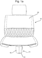
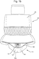
- Figures 1a-1d depict the progression of the footrest 12 from the stowed position (shown in Figure 1a ) to the deployed position (shown in Figure 1d ).
- Figures 1b and 1c depict intermediate positions between the stowed and deployed positions.
- the footrest 12 is bendable and is in a bent configuration when in the stowed position (as shown in Figure 1a ) and a flat configuration when in the deployed position (as shown in Figure 1d ).
- the seat assembly 30 may comprise an upstanding structural support 40, which supports the seat 20.
- the footrest 12 may be bent about the structural support 40 when in the stowed position.
- the footrest 12 comprises a first surface 14 upon which an occupant of the seat 20 may rest their feet.
- the footrest 12 may be movable such that the first surface 14 of the footrest 12 faces the structural support 40 when in the stowed position. So that the first surface 14 may face the structural support 40, the footrest 12 may rotate between the stowed and deployed positions.
- the footrest 12 may have a proximal end 12a closest to the seat 20 when in the deployed position and a distal end 12b furthest from the seat 20 when in the deployed position and the proximal end 12a may move to be in a position lower than the distal end 12b when the footrest 12 is in the stowed position.
- the proximal end 12a may move downwards relative to the distal end 12b as the footrest 12 rotates from the deployed position to the stowed position.
- the proximal end 12a of the footrest 12 may be adjacent to, e.g. touching, the seat 20 when in the deployed position. Additionally or alternatively, the footrest 12 may form a continuation of the seat 20 when in the deployed position, e.g. so as to provide an ergonomic surface to support the lower legs and/or feet of the occupant.
- the first surface 14 of the footrest 12 may be padded, e.g. so as to provide a soft surface for the occupant of the seat to rest their feet or lower legs.
- the footrest 12 may comprise a second surface 16 opposite the first surface 14. In contrast to the first surface 14, the second surface 16 may not be padded. The second surface 16 may be flush with surrounding portions of the seat assembly 30 when the footrest 12 is in the stowed position.
- the footrest assembly 10 may further comprise a support mechanism 50 configured to connect the footrest 12 to the seat assembly 30.
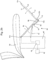
- the support mechanism 50 comprises an arm 52, which is elongate and has a first end 52a and a second end 52b.
- the first end 52a is rotatably coupled to the seat assembly 30.
- the first end 52a of the arm 52 may be rotatably coupled to the structural support 40, e.g. at or towards a top end of the structural support.
- the arm 52 may rotate relative to the seat assembly 30 about an axis that is parallel to a lateral direction of the seat 20.
- the arm 52 may be rotatably coupled to the footrest 12 at or near the second end 52b of the arm.
- the arm 52 and the footrest 12 may be rotatably coupled at a point that is set back from the proximal end 12a of the footrest 12. As for the first end, the arm 52 may rotate relative to the footrest 12 about an axis parallel to the lateral direction of the seat 20.
- the support mechanism 50 may comprise a first actuator 54 configured to rotate the arm 52 relative to the seat assembly 30.
- the first actuator 54 may be a linear actuator.
- One end of the first actuator 54 may be coupled to the structural support 40 and another end of the first actuator may be coupled to the arm 52. Accordingly, extension and retraction of the first actuator may cause the arm 52 to rotate relative to the seat assembly 30.
- Figures 2a-2c depict the progressive rotation of the arm 52 as the first actuator extends.
- Figure 2 shows the actuator 54 being a linear actuator, it is also envisaged that the actuator may take another form e.g. a rotary motor or any other type of actuator.
- the support mechanism 50 may further comprise a second actuator 56 configured to rotate the footrest 12 relative to the arm 52.
- the second actuator 56 may be a linear actuator, an end of which is connected to the arm 52 and the opposite end connected to the footrest 12.
- the second actuator 56 is coupled closer to the proximal end 12a of the footrest 12 than the arm 52.
- the second actuator 56 may also be coupled to the arm 52 via a projection 53 extending from the arm 52 so that the second actuator may be coupled to the arm 52 at a point spaced apart from a longitudinal axis of the arm.
- the projection 53 may improve the leverage of the second actuator 56.
- the footrest 12 rotates away from the arm 52.
- the arm 52 and footrest 12 may move from the stowed position, in which the arm 52 and footrest 12 are disposed at an acute angle relative to each other, to the deployed position in which the arm 52 and footrest 12 are at a non-acute angle (e.g. an obtuse angle).
- Figures 2a-2c depict the progression of the rotation of the footrest 12 relative to the arm 52 from the stowed position to the deployed position.
- Figure 2 depicts the second actuator 56 being a linear actuator, it is also envisaged that the second actuator may be a rotary actuator, such as a motor or any other type of actuator.
- the support mechanism 50 may comprise a linkage that is configured so that rotation of the arm relative to the seat assembly causes the footrest to rotate relative to the arm.
- a linkage may comprise a four bar link type mechanism or any other type of linkage.
- the second actuator 56 may be omitted and the first actuator 54 may drive rotation of both the arm relative to the seat assembly and the footrest relative to the arm.
- Rotation of the footrest 12 relative to the arm 52 may be limited by virtue of respective abutment surfaces 15, 55 on the footrest and arm that engage when the footrest is in the deployed position. Engagement of the abutment surfaces 15, 55 may prevent rotation of the footrest past the deployed position.
- the deployable footrest assembly 10 may further comprise a controller 60 to control components of the deployable footrest assembly.
- the controller 60 may be operatively coupled to the first actuator 54 so as to selectively actuate the first actuator.
- the controller 60 may also be operatively coupled to the second actuator to selectively actuate the second actuator.
- the controller 60 may be operatively coupled to a user input device 62, which an occupant of the seat 20 may interface with to select the desired position of the footrest 12.
- the controller 60 may be configured to actuate the first and second actuators 54, 56 so as to move the footrest 12 between the stowed and deployed positions.
- the controller 60 may control the movement of the arm 52 and footrest 12 to allow the footrest assembly to move between the deployed and stowed positions.
- the first and second actuators 54, 56 may be actuated at the appropriate rates and/or concurrently for at least a portion of their travel so that the footrest 12 does not impinge upon an underside of the seat 20.
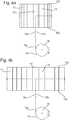
- the footrest 12 may move between a bent configuration (as depicted in Figures 3a and 4a ) and a substantially flat configuration (as depicted in Figures 3c and 4c ).
- Figures 3b and 4b depict an intermediate configuration between the bent and flat configurations.
- Figures 4a-4c depict a plan view of the footrest 12 as the footrest moves from the bent configuration to the flat configuration and corresponds to the views shown in Figures 3a-3c respectively.
- the footrest 12 may comprise a plurality of elongate members 70, which extend from the proximal end 12a of the footrest to the distal end 12b. Each of the elongate members may be rotatably coupled to an adjacent one of the elongate members. The plurality of elongate members may be arranged in a side-by-side fashion. Accordingly, the footrest 12 may bend about a plurality of bending axes so as to form a curve when bent.
- the footrest 12 may comprise a first layer 72 on a first side of the elongate members 70.
- the first layer 72 may provide the first surface 14.
- the first layer may comprise resistant, e.g. padded material.
- the footrest 12 may comprise a second layer 74 on a second side of the elongate member 70.
- the second layer 74 may provide the second surface 16.
- the first and/or second layers 72, 74 may expand and/or contract as the footrest 12 moves between the bent and flat configurations.
- the first and/or second layers may be attached to each or particular ones of the plurality of elongate members 70.
- Each of the elongate members 70 may comprise upper abutment side surfaces 70a that may be configured to abut one another when the footrest is in the bent configuration. The upper abutment surfaces 70a may otherwise move apart when the footrest 12 moves away from the bent configuration. Additionally or alternatively, each of the elongate members 70 may comprise lower abutment side surfaces 70b that may abut when the footrest 12 is in the flat configuration. The lower abutment surfaces 70b may otherwise move apart as the footrest 12 moves away from the flat configuration.
- Each elongate member 70 may comprise a pair of upper abutment surfaces 70a on opposite sides of the elongate member, with each upper abutment surface 70a facing a neighbouring elongate member 70.
- each of the elongate members 70 may comprise a pair of lower abutment surfaces 70b on either side of the elongate member, with each of the lower abutment surfaces facing an adjacent elongate member 70.
- the lower abutment surfaces 70b of a particular elongate member 70 may be substantially parallel to each other. In this way, abutment of the lower abutment surfaces 70b may limit rotation of the elongate members 70 past the flat configuration.
- the upper abutment surfaces 70a of a particular elongate member 70 may be non-parallel, e.g. tapered, such that the upper abutment surfaces 70a abut in the bent configuration of the footrest.
- the elongate members 70 may be successively rotatably coupled to one another by virtue of couplings 70c.
- the elongate members 70 may be rotatably coupled to a neighbouring elongate member 70 at the transition between the upper and lower abutment surfaces 70a, 70b.
- the width of the elongate members 70 may be the same or may vary.
- the elongate members 70 at the lateral edges of the footrest 12 may be wider than the elongate members away from the lateral edges. As such, the footrest 12 may form a "U" shape when bent.
- the footrest 12 may further comprise first and second cable portions 76a, 76b.
- the first and second cable portions 76a, 76b may pass through successive ones of the elongate members 70.
- the first and second cable portions 76a, 76b may pass through an upper region of the elongate members 70 comprising the upper abutment surfaces 70a.
- the first cable portion 76a may be provided on a first lateral side of the footrest 12 and the second cable portion 76b may be provided on a second lateral side of the footrest 12.
- the first and second cable portions 76a, 76b may extend laterally, e.g. from a mid-point of the footrest to the lateral ends of the footrest.
- the first and second cable portions 76a, 76b may slidably pass through the elongate members 70. Distal ends of the first and second cable portions 76a, 76b may be coupled to the elongate members 70 at the lateral ends of the footrest.
- the first and second cable portions 76a, 76b may come together in a central elongate member 70' in which the first and second cable portions may extend in a longitudinal direction of the elongate member 70'.
- the central elongate member 70' may correspond to the portion of the footrest 12 depicted in Figs 2a-c .
- the first and second cable portions 76a, 76b may be coupled to a third actuator 78 configured to selectively pull the first and second cable portions 76a, 76b.
- the third actuator 78 may comprise a motor with a reel 79 about which the first and second cable portions 76a, 76b or a further cable portion 76c connected to the first and second cable portions is wound.
- the first and second cable portions 76a, 76b and/or the further cable portion 76c may pass through the arm 52 and extend into the seat assembly 30, e.g. into the support structure 40.
- the third actuator 78 may then be provided in the support structure 40.
- Rotation of the motor may pull the first and second cable portions 76a, 76b.
- the pulling force causes the footrest 12 to move into the bent configuration.
- unwinding the drum 79 may permit the footrest 12 to move into the flat configuration.
- the footrest assembly 10 may at least partially rely on gravity to move the footrest 12 into the flat configuration as the footrest 12 is moved into the deployed position.
- the third actuator 78 may unwind the first and second cable portions 78a, 78b (or further cable portion 78c) gradually as the footrest 12 moves into the deployed position to provide a smooth transition as gravity urges the footrest into the substantially flat configuration.
- the third actuator 78 may be activated so as to move the footrest 12 into the bent configuration.
- the third actuator 78 may be operatively coupled to the controller 60 and activated by the controller at the appropriate time.
Landscapes
- Engineering & Computer Science (AREA)
- Aviation & Aerospace Engineering (AREA)
- Transportation (AREA)
- Mechanical Engineering (AREA)
- Passenger Equipment (AREA)
Claims (15)
- Un ensemble repose-pieds déployable (10) pour un siège (20), l'ensemble repose-pieds déployable (10) comprenant :un repose-pieds (12) mobile entre une position rangée et une position déployée dans laquelle le repose-pieds (12) présente une première surface (14) sur laquelle un occupant du siège (20) peut poser ses pieds,dans lequel le repose-pieds (12) est pliable autour d'un support structurel vertical (40) pour le siège (20) de telle sorte que le repose-pieds (12) est plié autour du support structurel (40) dans la position rangée, etcaractérisé en ce quele repose-pieds (12) a une ligne médiane s'étendant à partir d'une extrémité proximale (12a) du repose-pieds (12) la plus proche du siège (20) lorsqu'il est dans la position déployée jusqu'à une extrémité distale (12b) la plus éloignée du siège (20) lorsqu'il est dans la position déployée et le repose-pieds (12) se plie autour d'un ou plusieurs axes de pliage sensiblement parallèles à la ligne médiane ou coïncidant avec celle-ci.
- L'ensemble repose-pieds déployable (10) selon la revendication 1, dans lequel le repose-pieds (12) a une extrémité proximale (12a) la plus proche du siège (20) lorsqu'il est dans la position déployée et une extrémité distale (12b) la plus éloignée du siège (20) lorsqu'il est dans la position déployée, dans lequel le repose-pieds (12) est configuré pour tourner entre les positions rangée et déployée de telle sorte que l'extrémité proximale (12a) du repose-pieds (12) se déplace vers une position plus basse que l'extrémité distale (12b) du repose-pieds (12) lorsqu'il est dans la position rangée.
- L'ensemble repose-pieds déployable (10) selon la revendication 1 ou 2, dans lequel le repose-pieds (12) est mobile de telle sorte que la première surface (14) du repose-pieds (12) fait face au support structurel (40) lorsqu'il est dans la position rangée.
- L'ensemble repose-pieds déployable (10) selon l'une quelconque des revendications précédentes, dans lequel l'ensemble repose-pieds (12) comprend en outre un mécanisme de support (50) relié au repose-pieds (12) et pouvant être fixé à un ensemble siège (30) comprenant le siège (20) et le support structurel (40).
- L'ensemble repose-pieds déployable (10) selon la revendication 4, dans lequel le mécanisme de support (50) comprend un bras (52), une première extrémité (52a) du bras (52) pouvant être reliée de manière rotative à l'ensemble siège (30) et une deuxième extrémité (52b) du bras (52) étant reliée de manière rotative au repose-pieds (12).
- L'ensemble repose-pieds déployable (10) selon la revendication 5, dans lequel la rotation du repose-pieds (12) par rapport au bras (52) est limitée en raison des surfaces de butée respectives sur le repose-pieds (12) et le bras (52) qui s'engagent lorsque le repose-pieds (12) est dans la position déployée.
- L'ensemble repose-pieds déployable (10) selon la revendication 5 ou 6, dans lequel le mécanisme de support (50) comprend une liaison configurée de telle sorte que la rotation du bras (52) par rapport à l'ensemble siège (30) amène le repose-pieds (12) à tourner par rapport au bras (52).
- L'ensemble repose-pieds déployable (10) selon l'une quelconque des revendications 5 à 7, dans lequel le mécanisme de support (50) comprend un premier actionneur (54) configuré pour faire tourner le bras (52) par rapport à l'ensemble siège (30).
- L'ensemble repose-pieds déployable (10) selon l'une quelconque des revendications 5 à 8, dans lequel le mécanisme de support (50) comprend un deuxième actionneur (56) configuré pour faire tourner le repose-pieds (12) par rapport au bras (52).
- L'ensemble repose-pieds déployable (10) selon l'une quelconque des revendications précédentes, dans lequel le repose-pieds (12) se plie autour d'une pluralité d'axes de pliage de manière à former une courbe lorsqu'il est plié.
- L'ensemble repose-pieds déployable (10) selon l'une quelconque des revendications précédentes, dans lequel le repose-pieds (12) se plie autour des axes de pliage lorsque le repose-pieds (12) se déplace entre les positions déployée et rangée.
- L'ensemble repose-pieds déployable (10) selon l'une quelconque des revendications précédentes, dans lequel le repose-pieds (12) est configuré de manière à ne pas pouvoir être plié au-delà de la position déployée.
- L'ensemble repose-pieds déployable (10) selon l'une quelconque des revendications précédentes, dans lequel le repose-pieds (12) se déploie en une configuration plate en raison de la gravité.
- L'ensemble repose-pieds déployable (10) selon l'une quelconque des revendications précédentes, dans lequel l'ensemble repose-pieds déployable (10) comprend un mécanisme configuré pour déplacer le repose-pieds (12) dans une configuration pliée.
- Un procédé de rangement d'un repose-pieds (12) pour un siège (20), le procédé comprenant :le déplacement du repose-pieds (12) à partir d'une position déployée, dans laquelle le repose-pieds (12) présente une première surface (14) sur laquelle un occupant du siège (20) peut poser ses pieds, jusqu'à une position rangée, dans lequel le repose-pieds (12) a une ligne médiane s'étendant à partir d'une extrémité proximale (12a) du repose-pieds (12) la plus proche du siège (20) lorsqu'il est dans la position déployée jusqu'à une extrémité distale (12b) la plus éloignée du siège (20) lorsqu'il est dans la position déployée et le repose-pieds (12) se plie autour d'un ou plusieurs axes de pliage sensiblement parallèles à la ligne médiane ou coïncidant avec celle-ci ; etle pliage du repose-pieds (12) autour d'un support structurel vertical (40) pour le siège (20) de telle sorte que le repose-pieds (12) est plié autour du support structurel (40) dans la position rangée.
Applications Claiming Priority (1)
| Application Number | Priority Date | Filing Date | Title |
|---|---|---|---|
| GB1708255.3A GB2563003B (en) | 2017-05-23 | 2017-05-23 | A Deployable footrest |
Publications (2)
| Publication Number | Publication Date |
|---|---|
| EP3406483A1 EP3406483A1 (fr) | 2018-11-28 |
| EP3406483B1 true EP3406483B1 (fr) | 2020-10-14 |
Family
ID=59220733
Family Applications (1)
| Application Number | Title | Priority Date | Filing Date |
|---|---|---|---|
| EP18156106.9A Active EP3406483B1 (fr) | 2017-05-23 | 2018-02-09 | Repose-pieds déployable |
Country Status (4)
| Country | Link |
|---|---|
| US (1) | US10368648B2 (fr) |
| EP (1) | EP3406483B1 (fr) |
| CN (1) | CN108928280B (fr) |
| GB (1) | GB2563003B (fr) |
Families Citing this family (3)
| Publication number | Priority date | Publication date | Assignee | Title |
|---|---|---|---|---|
| JP6421365B2 (ja) * | 2017-02-10 | 2018-11-14 | 本田技研工業株式会社 | 車両シート制御システム、車両シートの制御方法、およびプログラム |
| DE102019203553A1 (de) * | 2019-03-15 | 2020-09-17 | Volkswagen Aktiengesellschaft | Unterschenkelstützeinrichtung für einen Fahrzeugsitz, Fahrzeugsitz |
| DE102021116347A1 (de) * | 2021-06-24 | 2022-12-29 | Bayerische Motoren Werke Aktiengesellschaft | Fahrzeugsitz mit einer Fußstütze |
Family Cites Families (43)
| Publication number | Priority date | Publication date | Assignee | Title |
|---|---|---|---|---|
| DE267425C (fr) | ||||
| US402130A (en) * | 1889-04-30 | George p | ||
| US2918964A (en) * | 1956-07-31 | 1959-12-29 | Braun Francois | Leg-rest for a seat |
| US3087757A (en) * | 1961-04-14 | 1963-04-30 | Modecraft Company Inc | Chair |
| US3679257A (en) * | 1970-05-15 | 1972-07-25 | Jacuzzi Research Inc | Foldable wheel chair |
| US4013318A (en) * | 1976-02-25 | 1977-03-22 | Piper James G | Portable footrest |
| US4455050A (en) * | 1981-06-22 | 1984-06-19 | Kubek John A | Clot preventing chair and attachments |
| US4819987A (en) * | 1987-11-18 | 1989-04-11 | Weber Aircraft | Aircraft seat leg support release device |
| DD267425A1 (de) * | 1987-12-03 | 1989-05-03 | Dresden Designprojekt | Sitzmoebel, das gleichwertig als stuhl und als balance-sitz nutzbar ist |
| US5188383A (en) * | 1991-10-03 | 1993-02-23 | Thompson Josephine M | User-collapsible wheelchair |
| BR9502131A (pt) * | 1995-05-23 | 1997-08-26 | Lafer S A Ind E Comercio | Poltrona |
| NO303045B1 (no) * | 1995-06-16 | 1998-05-25 | Terje Steinar Olsen | Stol med fot/leggst÷tte |
| US5556167A (en) * | 1995-06-30 | 1996-09-17 | Johnson Siemion; Helen F. | Collapsible foot rest for seat backs |
| US5795017A (en) * | 1996-11-18 | 1998-08-18 | Zimmerman; Matthew K. | Stowable fish fighting chair |
| US5890766A (en) * | 1997-08-04 | 1999-04-06 | Tsai; Chun Fa | Foot rest assembly for chairs |
| US6155645A (en) * | 1997-10-02 | 2000-12-05 | Bedrich; Achim | Rest chair |
| IT1318407B1 (it) * | 2000-03-17 | 2003-08-25 | C I A R S R L Ora C I A R S P | Pediera estensibile, particolarmente per poltrone, divani e simili. |
| US6382727B1 (en) * | 2000-12-18 | 2002-05-07 | Peter B. Pickard | Foldable chair |
| DE10209186B4 (de) * | 2002-03-04 | 2007-10-18 | Daimlerchrysler Ag | Fahrzeugsitz mit Fußstütze |
| US6619748B1 (en) * | 2002-08-13 | 2003-09-16 | Shin Yeh Enterprise Co., Ltd. | Chair having a crank mechanism for moving a footrest between extended and retracted positions relative to a seat |
| US6832741B2 (en) * | 2002-11-08 | 2004-12-21 | Alicja Jarosz | Aircraft seat footrest system and method |
| US7080887B2 (en) * | 2003-08-14 | 2006-07-25 | Taiwan Shin Yeh Enterprise Co., Ltd. | Chair with foldable leg rest |
| JP4643943B2 (ja) * | 2004-07-30 | 2011-03-02 | 株式会社岡村製作所 | 椅子 |
| JP2006271497A (ja) * | 2005-03-28 | 2006-10-12 | Coleman Co Inc:The | フットレスト付き折畳みチェア |
| US7108329B1 (en) * | 2005-11-15 | 2006-09-19 | Robert Clough | Seating unit with retractable footrest |
| US7322655B1 (en) * | 2006-09-08 | 2008-01-29 | Aloha Investments, Llc | Footrest |
| WO2010114814A1 (fr) * | 2009-03-30 | 2010-10-07 | Weber Aircraft Llc | Repose-jambes pour sièges passager |
| CN201418548Y (zh) * | 2009-06-08 | 2010-03-10 | 王宇恒 | 一种椅子 |
| SG161204A1 (en) * | 2010-03-12 | 2010-05-27 | Manju Sarkar | Chair providing enhanced health care and comfort |
| DE102010012767A1 (de) * | 2010-03-25 | 2011-09-29 | Audi Ag | Vorrichtung zur Auflage der Füße eines Passagiers eines Kraftfahrzeugs |
| JP5447139B2 (ja) * | 2010-04-23 | 2014-03-19 | トヨタ紡織株式会社 | 車両用シート |
| US20120080912A1 (en) * | 2010-10-04 | 2012-04-05 | Rosemary Perera | Footrest |
| US7954900B2 (en) * | 2010-12-30 | 2011-06-07 | Totada R Shantha | Leg supporting device for use behind a head rest for air and vehicular travel |
| US8864237B2 (en) * | 2011-05-17 | 2014-10-21 | Mac Ventures, L.L.C. | Footrest apparatus and method |
| JP5949096B2 (ja) * | 2012-04-25 | 2016-07-06 | アイシン精機株式会社 | オットマン装置 |
| US8794706B2 (en) * | 2012-06-20 | 2014-08-05 | Chang Chen Lin | Leg rest assembly for a chair |
| US8905483B2 (en) * | 2012-11-12 | 2014-12-09 | Compass Designs LLC | Adjustable footrest |
| AU2014342531A1 (en) * | 2013-10-28 | 2016-05-12 | L & P Property Management Company | Zero-wall clearance linkage mechanism for providing additional layout |
| DE102014207972A1 (de) * | 2014-04-28 | 2015-10-29 | Kintec-Solution Gmbh | Sitzmöbelstück und Beschlag hierfür |
| US10166902B2 (en) * | 2014-05-21 | 2019-01-01 | Jennifer CAYZER | Travel support device |
| US9295333B2 (en) * | 2014-06-25 | 2016-03-29 | Wan-Yu Li | Foldable leg rest |
| US9566888B2 (en) * | 2015-04-01 | 2017-02-14 | Ford Global Technologies, Llc | Vehicle seat having extendable bolsters and thigh supports |
| TWI597190B (zh) * | 2015-08-11 | 2017-09-01 | 國立清華大學 | 可調式踏墊組件及車用安全座椅 |
-
2017
- 2017-05-23 GB GB1708255.3A patent/GB2563003B/en not_active Expired - Fee Related
-
2018
- 2018-02-09 EP EP18156106.9A patent/EP3406483B1/fr active Active
- 2018-04-11 US US15/950,501 patent/US10368648B2/en active Active
- 2018-05-16 CN CN201810466566.1A patent/CN108928280B/zh active Active
Non-Patent Citations (1)
| Title |
|---|
| None * |
Also Published As
| Publication number | Publication date |
|---|---|
| GB2563003A (en) | 2018-12-05 |
| CN108928280A (zh) | 2018-12-04 |
| US20180338619A1 (en) | 2018-11-29 |
| GB2563003B (en) | 2019-10-02 |
| GB201708255D0 (en) | 2017-07-05 |
| US10368648B2 (en) | 2019-08-06 |
| EP3406483A1 (fr) | 2018-11-28 |
| CN108928280B (zh) | 2025-06-03 |
Similar Documents
| Publication | Publication Date | Title |
|---|---|---|
| EP3406483B1 (fr) | Repose-pieds déployable | |
| GB2563007B (en) | A deployable headrest | |
| CN106901497B (zh) | 可收起桌子总成 | |
| EP2823796A1 (fr) | Fauteuil roulant avec capacité d'inclinaison | |
| CN111216606B (zh) | 车辆座椅的高度调节装置 | |
| US20170225592A1 (en) | Vehicle seat and method for adjusting a vehicle seat | |
| CN101722872B (zh) | 车辆座椅滑动装置 | |
| EP2537444B1 (fr) | Dispositif de meuble | |
| EP2457468A1 (fr) | Dispositif de meuble | |
| CN102574574A (zh) | 用于可调节体在其在支撑结构部件上的调节期间的运动导引的调节机构、用于增升体的运动调节的调节机构和包括类似调节机构的增升系统 | |
| US9894999B2 (en) | Mechanism for an office chair | |
| US10350121B2 (en) | Electrically powered wheelchair with an armrest adjustment arrangement | |
| CN113459917A (zh) | 车辆的可移动桌组件 | |
| CN113286723A (zh) | 用于机动车的控制台 | |
| EP3774632B1 (fr) | Améliorations apportées ou liées à des chaises pliantes | |
| EP3140154B1 (fr) | Levier de déverrouillage servant au réglage d'un siège de véhicule et siège de véhicule | |
| CN110654287B (zh) | 用于车辆座椅的腿部支撑件 | |
| EP3050548A1 (fr) | Fauteuil élévateur inclinable | |
| EP2172136B1 (fr) | Siège doté d'un élément d'assise et d'un élément de dossier | |
| CN101106920A (zh) | 腰部支撑设备 | |
| KR102565208B1 (ko) | 운동 전환 장치 | |
| EP3031991A1 (fr) | Dispositif d'appui | |
| EP3544564A1 (fr) | Mécanisme pour un élévateur à ciseaux ou un système d'inclinaison | |
| CN101472507A (zh) | 头枕释放机构 | |
| JP4934878B2 (ja) | 椅子 |
Legal Events
| Date | Code | Title | Description |
|---|---|---|---|
| PUAI | Public reference made under article 153(3) epc to a published international application that has entered the european phase |
Free format text: ORIGINAL CODE: 0009012 |
|
| STAA | Information on the status of an ep patent application or granted ep patent |
Free format text: STATUS: REQUEST FOR EXAMINATION WAS MADE |
|
| 17P | Request for examination filed |
Effective date: 20181011 |
|
| AK | Designated contracting states |
Kind code of ref document: A1 Designated state(s): AL AT BE BG CH CY CZ DE DK EE ES FI FR GB GR HR HU IE IS IT LI LT LU LV MC MK MT NL NO PL PT RO RS SE SI SK SM TR |
|
| AX | Request for extension of the european patent |
Extension state: BA ME |
|
| GRAP | Despatch of communication of intention to grant a patent |
Free format text: ORIGINAL CODE: EPIDOSNIGR1 |
|
| STAA | Information on the status of an ep patent application or granted ep patent |
Free format text: STATUS: GRANT OF PATENT IS INTENDED |
|
| RIC1 | Information provided on ipc code assigned before grant |
Ipc: A47C 7/50 20060101ALI20200422BHEP Ipc: B64D 11/06 20060101ALI20200422BHEP Ipc: B60N 3/06 20060101ALI20200422BHEP Ipc: B60N 2/90 20180101AFI20200422BHEP |
|
| INTG | Intention to grant announced |
Effective date: 20200507 |
|
| GRAS | Grant fee paid |
Free format text: ORIGINAL CODE: EPIDOSNIGR3 |
|
| GRAA | (expected) grant |
Free format text: ORIGINAL CODE: 0009210 |
|
| STAA | Information on the status of an ep patent application or granted ep patent |
Free format text: STATUS: THE PATENT HAS BEEN GRANTED |
|
| RBV | Designated contracting states (corrected) |
Designated state(s): AL AT BE BG CH CY CZ DE DK EE ES FI FR GR HR HU IE IS IT LI LT LU LV MC MK MT NL NO PL PT RO RS SE SI SK SM TR |
|
| AK | Designated contracting states |
Kind code of ref document: B1 Designated state(s): AL AT BE BG CH CY CZ DE DK EE ES FI FR GR HR HU IE IS IT LI LT LU LV MC MK MT NL NO PL PT RO RS SE SI SK SM TR |
|
| REG | Reference to a national code |
Ref country code: AT Ref legal event code: REF Ref document number: 1323249 Country of ref document: AT Kind code of ref document: T Effective date: 20201015 Ref country code: CH Ref legal event code: EP |
|
| REG | Reference to a national code |
Ref country code: DE Ref legal event code: R096 Ref document number: 602018008590 Country of ref document: DE |
|
| REG | Reference to a national code |
Ref country code: IE Ref legal event code: FG4D |
|
| REG | Reference to a national code |
Ref country code: DE Ref legal event code: R082 Ref document number: 602018008590 Country of ref document: DE Representative=s name: HL KEMPNER PATENTANWAELTE, SOLICITORS (ENGLAND, DE Ref country code: DE Ref legal event code: R082 Ref document number: 602018008590 Country of ref document: DE Representative=s name: HL KEMPNER PATENTANWALT, RECHTSANWALT, SOLICIT, DE Ref country code: DE Ref legal event code: R082 Ref document number: 602018008590 Country of ref document: DE Representative=s name: HL KEMPNER PARTG MBB, DE |
|
| REG | Reference to a national code |
Ref country code: AT Ref legal event code: MK05 Ref document number: 1323249 Country of ref document: AT Kind code of ref document: T Effective date: 20201014 |
|
| REG | Reference to a national code |
Ref country code: NL Ref legal event code: MP Effective date: 20201014 |
|
| PG25 | Lapsed in a contracting state [announced via postgrant information from national office to epo] |
Ref country code: FI Free format text: LAPSE BECAUSE OF FAILURE TO SUBMIT A TRANSLATION OF THE DESCRIPTION OR TO PAY THE FEE WITHIN THE PRESCRIBED TIME-LIMIT Effective date: 20201014 Ref country code: RS Free format text: LAPSE BECAUSE OF FAILURE TO SUBMIT A TRANSLATION OF THE DESCRIPTION OR TO PAY THE FEE WITHIN THE PRESCRIBED TIME-LIMIT Effective date: 20201014 Ref country code: PT Free format text: LAPSE BECAUSE OF FAILURE TO SUBMIT A TRANSLATION OF THE DESCRIPTION OR TO PAY THE FEE WITHIN THE PRESCRIBED TIME-LIMIT Effective date: 20210215 Ref country code: NO Free format text: LAPSE BECAUSE OF FAILURE TO SUBMIT A TRANSLATION OF THE DESCRIPTION OR TO PAY THE FEE WITHIN THE PRESCRIBED TIME-LIMIT Effective date: 20210114 Ref country code: GR Free format text: LAPSE BECAUSE OF FAILURE TO SUBMIT A TRANSLATION OF THE DESCRIPTION OR TO PAY THE FEE WITHIN THE PRESCRIBED TIME-LIMIT Effective date: 20210115 |
|
| REG | Reference to a national code |
Ref country code: LT Ref legal event code: MG4D |
|
| PG25 | Lapsed in a contracting state [announced via postgrant information from national office to epo] |
Ref country code: BG Free format text: LAPSE BECAUSE OF FAILURE TO SUBMIT A TRANSLATION OF THE DESCRIPTION OR TO PAY THE FEE WITHIN THE PRESCRIBED TIME-LIMIT Effective date: 20210114 Ref country code: SE Free format text: LAPSE BECAUSE OF FAILURE TO SUBMIT A TRANSLATION OF THE DESCRIPTION OR TO PAY THE FEE WITHIN THE PRESCRIBED TIME-LIMIT Effective date: 20201014 Ref country code: LV Free format text: LAPSE BECAUSE OF FAILURE TO SUBMIT A TRANSLATION OF THE DESCRIPTION OR TO PAY THE FEE WITHIN THE PRESCRIBED TIME-LIMIT Effective date: 20201014 Ref country code: IS Free format text: LAPSE BECAUSE OF FAILURE TO SUBMIT A TRANSLATION OF THE DESCRIPTION OR TO PAY THE FEE WITHIN THE PRESCRIBED TIME-LIMIT Effective date: 20210214 Ref country code: PL Free format text: LAPSE BECAUSE OF FAILURE TO SUBMIT A TRANSLATION OF THE DESCRIPTION OR TO PAY THE FEE WITHIN THE PRESCRIBED TIME-LIMIT Effective date: 20201014 Ref country code: AT Free format text: LAPSE BECAUSE OF FAILURE TO SUBMIT A TRANSLATION OF THE DESCRIPTION OR TO PAY THE FEE WITHIN THE PRESCRIBED TIME-LIMIT Effective date: 20201014 Ref country code: ES Free format text: LAPSE BECAUSE OF FAILURE TO SUBMIT A TRANSLATION OF THE DESCRIPTION OR TO PAY THE FEE WITHIN THE PRESCRIBED TIME-LIMIT Effective date: 20201014 |
|
| PG25 | Lapsed in a contracting state [announced via postgrant information from national office to epo] |
Ref country code: NL Free format text: LAPSE BECAUSE OF FAILURE TO SUBMIT A TRANSLATION OF THE DESCRIPTION OR TO PAY THE FEE WITHIN THE PRESCRIBED TIME-LIMIT Effective date: 20201014 Ref country code: HR Free format text: LAPSE BECAUSE OF FAILURE TO SUBMIT A TRANSLATION OF THE DESCRIPTION OR TO PAY THE FEE WITHIN THE PRESCRIBED TIME-LIMIT Effective date: 20201014 |
|
| REG | Reference to a national code |
Ref country code: DE Ref legal event code: R097 Ref document number: 602018008590 Country of ref document: DE |
|
| PG25 | Lapsed in a contracting state [announced via postgrant information from national office to epo] |
Ref country code: SK Free format text: LAPSE BECAUSE OF FAILURE TO SUBMIT A TRANSLATION OF THE DESCRIPTION OR TO PAY THE FEE WITHIN THE PRESCRIBED TIME-LIMIT Effective date: 20201014 Ref country code: RO Free format text: LAPSE BECAUSE OF FAILURE TO SUBMIT A TRANSLATION OF THE DESCRIPTION OR TO PAY THE FEE WITHIN THE PRESCRIBED TIME-LIMIT Effective date: 20201014 Ref country code: SM Free format text: LAPSE BECAUSE OF FAILURE TO SUBMIT A TRANSLATION OF THE DESCRIPTION OR TO PAY THE FEE WITHIN THE PRESCRIBED TIME-LIMIT Effective date: 20201014 Ref country code: LT Free format text: LAPSE BECAUSE OF FAILURE TO SUBMIT A TRANSLATION OF THE DESCRIPTION OR TO PAY THE FEE WITHIN THE PRESCRIBED TIME-LIMIT Effective date: 20201014 Ref country code: CZ Free format text: LAPSE BECAUSE OF FAILURE TO SUBMIT A TRANSLATION OF THE DESCRIPTION OR TO PAY THE FEE WITHIN THE PRESCRIBED TIME-LIMIT Effective date: 20201014 Ref country code: EE Free format text: LAPSE BECAUSE OF FAILURE TO SUBMIT A TRANSLATION OF THE DESCRIPTION OR TO PAY THE FEE WITHIN THE PRESCRIBED TIME-LIMIT Effective date: 20201014 |
|
| PLBE | No opposition filed within time limit |
Free format text: ORIGINAL CODE: 0009261 |
|
| STAA | Information on the status of an ep patent application or granted ep patent |
Free format text: STATUS: NO OPPOSITION FILED WITHIN TIME LIMIT |
|
| PG25 | Lapsed in a contracting state [announced via postgrant information from national office to epo] |
Ref country code: DK Free format text: LAPSE BECAUSE OF FAILURE TO SUBMIT A TRANSLATION OF THE DESCRIPTION OR TO PAY THE FEE WITHIN THE PRESCRIBED TIME-LIMIT Effective date: 20201014 |
|
| 26N | No opposition filed |
Effective date: 20210715 |
|
| PG25 | Lapsed in a contracting state [announced via postgrant information from national office to epo] |
Ref country code: MC Free format text: LAPSE BECAUSE OF FAILURE TO SUBMIT A TRANSLATION OF THE DESCRIPTION OR TO PAY THE FEE WITHIN THE PRESCRIBED TIME-LIMIT Effective date: 20201014 |
|
| REG | Reference to a national code |
Ref country code: BE Ref legal event code: MM Effective date: 20210228 |
|
| PG25 | Lapsed in a contracting state [announced via postgrant information from national office to epo] |
Ref country code: CH Free format text: LAPSE BECAUSE OF NON-PAYMENT OF DUE FEES Effective date: 20210228 Ref country code: AL Free format text: LAPSE BECAUSE OF FAILURE TO SUBMIT A TRANSLATION OF THE DESCRIPTION OR TO PAY THE FEE WITHIN THE PRESCRIBED TIME-LIMIT Effective date: 20201014 Ref country code: LU Free format text: LAPSE BECAUSE OF NON-PAYMENT OF DUE FEES Effective date: 20210209 Ref country code: LI Free format text: LAPSE BECAUSE OF NON-PAYMENT OF DUE FEES Effective date: 20210228 Ref country code: IT Free format text: LAPSE BECAUSE OF FAILURE TO SUBMIT A TRANSLATION OF THE DESCRIPTION OR TO PAY THE FEE WITHIN THE PRESCRIBED TIME-LIMIT Effective date: 20201014 |
|
| PG25 | Lapsed in a contracting state [announced via postgrant information from national office to epo] |
Ref country code: SI Free format text: LAPSE BECAUSE OF FAILURE TO SUBMIT A TRANSLATION OF THE DESCRIPTION OR TO PAY THE FEE WITHIN THE PRESCRIBED TIME-LIMIT Effective date: 20201014 |
|
| PG25 | Lapsed in a contracting state [announced via postgrant information from national office to epo] |
Ref country code: IE Free format text: LAPSE BECAUSE OF NON-PAYMENT OF DUE FEES Effective date: 20210209 Ref country code: FR Free format text: LAPSE BECAUSE OF NON-PAYMENT OF DUE FEES Effective date: 20210228 |
|
| PG25 | Lapsed in a contracting state [announced via postgrant information from national office to epo] |
Ref country code: IS Free format text: LAPSE BECAUSE OF FAILURE TO SUBMIT A TRANSLATION OF THE DESCRIPTION OR TO PAY THE FEE WITHIN THE PRESCRIBED TIME-LIMIT Effective date: 20210214 |
|
| PG25 | Lapsed in a contracting state [announced via postgrant information from national office to epo] |
Ref country code: BE Free format text: LAPSE BECAUSE OF NON-PAYMENT OF DUE FEES Effective date: 20210228 |
|
| PG25 | Lapsed in a contracting state [announced via postgrant information from national office to epo] |
Ref country code: CY Free format text: LAPSE BECAUSE OF FAILURE TO SUBMIT A TRANSLATION OF THE DESCRIPTION OR TO PAY THE FEE WITHIN THE PRESCRIBED TIME-LIMIT Effective date: 20201014 |
|
| P01 | Opt-out of the competence of the unified patent court (upc) registered |
Effective date: 20230620 |
|
| PG25 | Lapsed in a contracting state [announced via postgrant information from national office to epo] |
Ref country code: HU Free format text: LAPSE BECAUSE OF FAILURE TO SUBMIT A TRANSLATION OF THE DESCRIPTION OR TO PAY THE FEE WITHIN THE PRESCRIBED TIME-LIMIT; INVALID AB INITIO Effective date: 20180209 |
|
| PG25 | Lapsed in a contracting state [announced via postgrant information from national office to epo] |
Ref country code: MK Free format text: LAPSE BECAUSE OF FAILURE TO SUBMIT A TRANSLATION OF THE DESCRIPTION OR TO PAY THE FEE WITHIN THE PRESCRIBED TIME-LIMIT Effective date: 20201014 |
|
| PG25 | Lapsed in a contracting state [announced via postgrant information from national office to epo] |
Ref country code: TR Free format text: LAPSE BECAUSE OF FAILURE TO SUBMIT A TRANSLATION OF THE DESCRIPTION OR TO PAY THE FEE WITHIN THE PRESCRIBED TIME-LIMIT Effective date: 20201014 |
|
| PG25 | Lapsed in a contracting state [announced via postgrant information from national office to epo] |
Ref country code: MT Free format text: LAPSE BECAUSE OF FAILURE TO SUBMIT A TRANSLATION OF THE DESCRIPTION OR TO PAY THE FEE WITHIN THE PRESCRIBED TIME-LIMIT Effective date: 20201014 |
|
| PGFP | Annual fee paid to national office [announced via postgrant information from national office to epo] |
Ref country code: DE Payment date: 20260115 Year of fee payment: 9 |