EP3406521B1 - Commande directionnelle anticouple de giravion à l'aide d'une soufflante centrifuge - Google Patents
Commande directionnelle anticouple de giravion à l'aide d'une soufflante centrifuge Download PDFInfo
- Publication number
- EP3406521B1 EP3406521B1 EP17185863.2A EP17185863A EP3406521B1 EP 3406521 B1 EP3406521 B1 EP 3406521B1 EP 17185863 A EP17185863 A EP 17185863A EP 3406521 B1 EP3406521 B1 EP 3406521B1
- Authority
- EP
- European Patent Office
- Prior art keywords
- centrifugal blower
- rotorcraft
- tail boom
- thrust
- control
- Prior art date
- Legal status (The legal status is an assumption and is not a legal conclusion. Google has not performed a legal analysis and makes no representation as to the accuracy of the status listed.)
- Active
Links
Images



Classifications
-
- B—PERFORMING OPERATIONS; TRANSPORTING
- B64—AIRCRAFT; AVIATION; COSMONAUTICS
- B64C—AEROPLANES; HELICOPTERS
- B64C27/00—Rotorcraft; Rotors peculiar thereto
- B64C27/82—Rotorcraft; Rotors peculiar thereto characterised by the provision of an auxiliary rotor or fluid-jet device for counter-balancing lifting rotor torque or changing direction of rotorcraft
-
- F—MECHANICAL ENGINEERING; LIGHTING; HEATING; WEAPONS; BLASTING
- F04—POSITIVE - DISPLACEMENT MACHINES FOR LIQUIDS; PUMPS FOR LIQUIDS OR ELASTIC FLUIDS
- F04D—NON-POSITIVE-DISPLACEMENT PUMPS
- F04D17/00—Radial-flow pumps, e.g. centrifugal pumps; Helico-centrifugal pumps
- F04D17/08—Centrifugal pumps
- F04D17/16—Centrifugal pumps for displacing without appreciable compression
-
- F—MECHANICAL ENGINEERING; LIGHTING; HEATING; WEAPONS; BLASTING
- F04—POSITIVE - DISPLACEMENT MACHINES FOR LIQUIDS; PUMPS FOR LIQUIDS OR ELASTIC FLUIDS
- F04D—NON-POSITIVE-DISPLACEMENT PUMPS
- F04D29/00—Details, component parts, or accessories
- F04D29/40—Casings; Connections of working fluid
- F04D29/42—Casings; Connections of working fluid for radial or helico-centrifugal pumps
- F04D29/44—Fluid-guiding means, e.g. diffusers
- F04D29/46—Fluid-guiding means, e.g. diffusers adjustable
- F04D29/462—Fluid-guiding means, e.g. diffusers adjustable especially adapted for elastic fluid pumps
-
- B—PERFORMING OPERATIONS; TRANSPORTING
- B64—AIRCRAFT; AVIATION; COSMONAUTICS
- B64C—AEROPLANES; HELICOPTERS
- B64C27/00—Rotorcraft; Rotors peculiar thereto
- B64C27/82—Rotorcraft; Rotors peculiar thereto characterised by the provision of an auxiliary rotor or fluid-jet device for counter-balancing lifting rotor torque or changing direction of rotorcraft
- B64C2027/8245—Rotorcraft; Rotors peculiar thereto characterised by the provision of an auxiliary rotor or fluid-jet device for counter-balancing lifting rotor torque or changing direction of rotorcraft using air jets
-
- B—PERFORMING OPERATIONS; TRANSPORTING
- B64—AIRCRAFT; AVIATION; COSMONAUTICS
- B64C—AEROPLANES; HELICOPTERS
- B64C27/00—Rotorcraft; Rotors peculiar thereto
- B64C27/82—Rotorcraft; Rotors peculiar thereto characterised by the provision of an auxiliary rotor or fluid-jet device for counter-balancing lifting rotor torque or changing direction of rotorcraft
- B64C2027/8254—Shrouded tail rotors, e.g. "Fenestron" fans
Definitions
- This disclosure relates generally to rotorcraft design, and more particularly, though not exclusively, to rotorcraft anti-torque and directional control.
- a rotorcraft requires some form of anti-torque and direction control in order to counteract the torque effect of the main rotor, and also to control the direction of the rotorcraft.
- a rotorcraft may include a tail rotor to provide anti-torque and direction control. Tail rotors, however, suffer from various safety and performance drawbacks.
- GB 892011 discloses a jet-propelled helicopter comprising a fuselage, a power source and a bladed rotor mounted on the fuselage and normally driven by reason of power developed in the power source.
- Each blade is hollow and has at its rear edge a slot extending inwardly from adjacent the blade tip.
- a flap is pivotally mounted at each slot to extend therealong and to control the direction of the jet issuing from the slot, the helicopter including control means to move the flaps cyclically and collectively.
- the power source functions to develop operating pressure in the hollow blade for the production of said jet which operating pressure is so low that in autorotation of the rotor upon failure of the power source the pressure produced by the rotor pump effect averaged over the length of the slot is sufficiently close to said operating pressure similarly averaged that the helicopter may still be controlled by said control means without the necessity for a change of blade angle. Air entering the interior of the hollow blades encounters little resistance in autorotation of the rotor.
- US 2015/191245 discloses a helicopter with a fuselage, at least one engine, a roll axis, at least one main rotor, and at least one housing mounted to said fuselage.
- An air inlet and an air outlet are provided along at least a part of a circumference of the at least one housing, said air inlet and said air outlet being formed by angularly offset and separate gaps between an inside segment and an outside segment essentially extending respectively longitudinally in direction of said roll axis.
- At least one rotatable compressor with a plurality of airfoil blades is provided radial inside said at least one housing between said air inlet and said air outlet said at least one rotatable compressor being drivable by said at least one engine about a fan axis and each chord of said airfoil blades is essentially radial oriented with regard to said fan axis.
- US 4660785 discloses a helicopter antitorque auxiliary propulsion system, comprising a propeller attached to the tail boom adapted for powered rotation to create a directed air flow rearward of the helicopter, including a duct encircling the propeller and a pair of stabaron doors hingedly mounted in the ducted airstream to divert the air flow at high speed for directional control and to close at low speed and allow the air flow to be diverted through openings in the duct for directional and antitorque control.
- a rotorcraft comprises a fuselage, a tail boom, a rotor system, and a centrifugal blower system.
- the centrifugal blower system comprises a centrifugal blower configured to generate thrust using an airflow, wherein the centrifugal blower is located within the tail boom.
- the centrifugal blower system also comprises a plurality of ducts configured to control the thrust generated by the centrifugal blower, wherein the plurality of ducts is located on a portion of the tail boom surrounding the centrifugal blower, and wherein the plurality of ducts comprises one or more adjustable ducts configured to vary a size of an associated duct opening.
- FIGURE 1 illustrates an example embodiment of a rotorcraft 100.
- Rotorcraft 100 includes a fuselage 110, a rotor system 120, and an empennage 130.
- the fuselage 110 is the main body of the rotorcraft, which includes a cabin for the crew, passengers, and/or cargo, and may also house certain mechanical and electrical components, such as the engine(s), transmission, and flight controls.
- the rotor system 120 includes a plurality of rotor blades 122 that are used to generate lift.
- the rotor blades 122 for example, can generate lift by rotating when torque is supplied by the engine(s).
- the pitch of each rotor blade 122 can be adjusted in order to selectively control direction, thrust, and lift for the rotorcraft 100.
- the empennage 130 of the rotorcraft includes a tail boom 132, a horizontal fin or stabilizer 139, and a vertical fin or stabilizer 138. Moreover, the tail boom 132 also houses a centrifugal blower system 134, described further below.
- Centrifugal blower system 134 is used to provide anti-torque control and direction or yaw control for rotorcraft 100.
- some rotorcraft may provide anti-torque and direction control using a traditional tail rotor and/or rudder.
- a traditional tail rotor impacts operator safety dramatically, however, as the exposed rotor is a significant safety hazard, particularly when located at or near the height of a person.
- a tail rotor presents a dangerous risk of contact with people and objects, such as powerlines and other wires, trees, fences, and so forth.
- There are also various performance drawbacks associated with a traditional tail rotor system including additional drag and excessive noise.
- Fenestron is an alternative tail rotor system that leverages a protective duct to reduce the safety risk presented by exposed rotor blades.
- Fenestron uses a "fan-in-tail" design that houses the rotor blades in a circular protective duct within the tail, thus reducing the risk of external contact with the tail rotor.
- Fenestron rotor systems suffer from various performance drawbacks. For example, Fenestron uses a thick duct to protect the rotor blades, and thus requires a bulky and more complex tail structure, resulting in increased weight, power requirements, manufacturing time, and cost.
- NOTAR No Tail Rotor
- NOTAR uses an internal axial fan located between the fuselage and tail boom to force airflow down the tail boom, and then redirects the airflow sideways (e.g., by 90 degrees) to force it to exit through a fixed opening on one side of the tail boom, thus generating thrust that can be used for anti-torque and directional control.
- NOTAR also uses a jet thruster and vertical stabilizer to augment the anti-torque and directional control provided by the internal axial fan.
- NOTAR systems suffer from various performance drawbacks. For example, redirecting the airflow by 90 degrees from its original direction reduces the thrust efficiency and increases complexity. Moreover, NOTAR uses a tail boom with a cylindrical shape rather than an airfoil shape, resulting in a less aerodynamic design that fails to leverage the benefits of a tail boom with an aerodynamic airfoil shape.
- rotorcraft 100 provides anti-torque and direction control using a centrifugal blower system 134 rather than a traditional tail rotor, rudder, or another alternative such as Fenestron or NOTAR.
- a centrifugal blower (not shown in FIG. 1 ) mounted internally within the aft end of tail boom 132 can be used to blow air radially to generate thrust (and lift) on either side of the tail boom.
- a plurality of ducts can be used to control the thrust generated by the centrifugal blower.
- variable aperture doors on both sides of the tail boom are used to direct the appropriate amount of thrust through the appropriate side(s) of the tail boom in order to provide anti-torque and directional control.
- the tail boom 132 can be designed using an airfoil shape to further improve the aerodynamics of the rotorcraft.
- centrifugal blower system 134 eliminates the need for a tail rotor and rudder.
- performance drawbacks associated with tail rotors e.g., safety risks, noise, drag
- the mechanical complexity, weight, and cost of the rotorcraft can be reduced (e.g., by eliminating tail rotor components such as the blades, intermediate gearboxes, and so forth).
- a centrifugal blower system 134 can be used in conjunction with a tail rotor and/or tail rudder, for example, to augment or improve the anti-torque and direction control, or provide redundancy in the event of a system failure.
- Centrifugal blower system 134 also provides various performance improvements over NOTAR systems. For example, centrifugal blower system 134 eliminates the need to redirect airflow by 90 degrees, which reduces complexity and improves the thrust efficiency. Centrifugal blower system 134 also improves anti-torque and direction control by enabling the direction and intensity of the thrust to be selectively controlled (e.g., by adjusting the aperture doors on the tail boom to direct the appropriate amount of airflow to the appropriate side(s) of the tail boom). Centrifugal blower system 134 can also be implemented using a tail boom with an airfoil shape, resulting in a design that is more aerodynamic than the cylindrical tail boom used by NOTAR systems. Accordingly, centrifugal blower system 134 provides numerous benefits over existing approaches, including improved safety, acoustics (e.g., by reducing noise), and performance, and reduced complexity, cost, and weight, among other examples.
- rotorcraft 100 of FIGURE 1 is merely illustrative of a variety of aircraft that can be used with embodiments described throughout this disclosure.
- Other aircraft implementations can include, for example, fixed wing airplanes, hybrid aircraft, tiltrotor aircraft, unmanned aircraft, gyrocopters, a variety of helicopter configurations, and drones, among other examples.
- FIGURE 2 illustrates an example embodiment of a centrifugal blower system 200 used for rotorcraft anti-torque and direction control.
- a centrifugal blower which may also be referred to as a squirrel cage blower, is a mechanical device for moving air and other gases.
- a centrifugal blower uses rotating impellers or fan blades to increase the speed and volume of an air stream and displace the air radially.
- a centrifugal blower may be a drum shape fan wheel, composed of a plurality of fan blades mounted around a hub that turns on a driveshaft.
- centrifugal blower is quiet, reliable, and capable of operating over a wide range of conditions.
- centrifugal blower system 200 uses a centrifugal blower 204 to provide rotorcraft anti-torque and direction control.
- the tail boom 202 of a rotorcraft is shown.
- the illustrated tail boom 202 is designed using an airfoil shape to further improve the aerodynamics of the rotorcraft.
- the tail boom 202 also includes a horizontal stabilizer fin 209 and a vertical stabilizer fin 208.
- a centrifugal blower 204 is mounted internally within the aft end of tail boom 202 (e.g., on the tail driveshaft), near the vertical fin 208. Unlike a traditional tail rotor, however, centrifugal blower 204 does not require a gearbox at the aft end of the tail boom 202.
- Centrifugal blower 204 includes an air intake that can be fed from the forward and aft ends of the tail boom 202.
- centrifugal blower 204 can be fed with airflow from the forward end of the tail boom 202 using air that enters through a duct positioned near the main rotor, and/or using an axial blower positioned at the forward end of the tail boom 202.
- centrifugal blower 204 can be fed with airflow from the aft end of the tail boom 202 using a tail boom 202 with an open aft end. Using the airflow from the intake, centrifugal blower 204 then expels air radially to generate thrust and lift on either side of the tail boom 202.
- variable aperture doors 206 and one or more Coanda slots 207 are positioned on tail boom 202 to direct the radial airflow from centrifugal blower 204 out through the side(s) of tail boom 202 in order to generate thrust.
- the portion of the tail boom 202 that houses centrifugal blower 204 includes variable aperture doors 206 on both sides of the tail boom 202, along with one or more Coanda slot(s) 207.
- the respective aperture doors 206 and Coanda slot(s) 207 are positioned on the tail boom 202 to direct the thrust generated by centrifugal blower 204 out through the sides of tail boom 202. In this manner, the resulting thrust can be leveraged for anti-torque and/or direction control.
- the Coanda slot(s) 207 can be used for anti-torque control.
- the Coanda slot 207 is positioned on the side of tail boom 202 towards the top, and angled to direct airflow down the side of tail boom 202.
- Centrifugal blower 204 forces air through the Coanda slot 207 and down the side of tail boom 202, producing a flow of air around the tail boom 202 known as the Coanda effect. This creates thrust and generates lift on the side of the tail boom 202, which helps counteract the steady torque of the main rotor when in hover.
- the airfoil shape of the tail boom 202 provides a moment arm for the generated thrust, and the tail boom 202 effectively functions as a "wing" flying in the downwash of the main rotor system, which aids in producing the requisite anti-torque.
- anti-torque may also be provided by a vertical stabilizer or fin 208.
- Coanda slot 207 may be a fixed aperture that is always open. In other embodiments, however, Coanda slot 207 may be an adjustable aperture that can be opened and closed (e.g., using a door or covering) as needed.
- variable aperture doors 206 can be used to provide both anti-torque and direction control, for example, by directing a variable amount of thrust from the centrifugal blower 204 out through the side(s) of tail boom 202.
- the variable aperture doors 206 are positioned on each side of the tail boom 202.
- the aperture doors 206 can be adjusted to vary the size of their respective openings, thus enabling a variable amount of thrust to be directed out either or both sides of tail boom 202.
- centrifugal blower system 200 can be used to blow air radially out of the side(s) of tail boom 202, thus generating thrust and lift on the side(s) of the tail boom 202, which can be used to provide anti-torque and direction control for a rotorcraft.
- the aperture doors 206 are positioned on each side of the tail boom 202 around centrifugal blower 204 (e.g., on the aft end of the tail boom 202), and can be opened and closed in order to direct the thrust generated by centrifugal blower 204.
- one door 206 may be fully open and the other door 206 may be fully closed.
- the entire thrust generated by centrifugal blower 204 is dedicated to anti-torque control, which may allow the blower to operate using less power.
- the aperture doors 206 may both be opened to different heights, resulting in split airflow, thus providing less anti-torque and more force in a particular direction. This enables a rotorcraft to yaw without a rudder, while still providing control to the pilot.
- centrifugal blower system 200 can be used to provide anti-torque and/or direction control for a rotorcraft.
- Centrifugal blower system 200 can be controlled by a pilot in the same manner as a traditional tail rotor, for example, using anti-torque pedals.
- the anti-torque pedals are used to adjust the aperture doors 206 of the centrifugal blower system 200, rather than to adjust the pitch of tail rotor blades.
- centrifugal blower 204 can be powered by a mechanical, electric, or hydraulic source.
- centrifugal blower system 200 may include a mechanism to turn off or disable centrifugal blower 204 (e.g., when the rotorcraft is traveling at high speeds and the anti-torque or direction control of centrifugal blower 204 is unnecessary).
- a rotorcraft may include a clutch that can be used to disengage and disable centrifugal blower 204.
- centrifugal blower 204 is electrically or hydraulically driven, a rotorcraft may include a control or switch that can be used to enable and disable centrifugal blower 204 (e.g., without using a clutch).
- centrifugal blower 204 may use fan blades with fixed pitch. In other embodiments, however, centrifugal blower 204 may use fan blades with variable collective pitch to manage the power required by centrifugal blower 204, and thus the centrifugal blower system 200 may also include a mechanism for controlling the pitch of the fan blades. Moreover, in some embodiments, the additional airflow created in the tail boom 202 by centrifugal blower 204 can be leveraged to provide a cooling system for the rotorcraft, for example, to cool the engine, exhaust, hydraulic systems, provide exhaust dilution, and so forth.
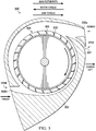
- FIGURE 3 illustrates a cross-section view of a centrifugal blower system 300.
- the illustrated cross-section view is from a perspective looking forward from the aft end of a tail boom 302 of a rotorcraft.
- centrifugal blower system 300 is implemented inside a tail boom 302 that has an aerodynamic airfoil shape.
- Tail boom 302 houses a centrifugal blower 304 that is mounted internally within the aft end of tail boom 302 (e.g., on the tail driveshaft).
- Centrifugal blower 304 includes a plurality of rotating impellers or fan blades 305.
- the fan blades 305 may be spaced unevenly to distribute noise across different frequencies, thus reducing the overall noise produced by centrifugal blower 304.
- Centrifugal blower 304 uses the rotating fan blades 305 to displace airflow radially while also increasing the speed and volume of the airflow, which generates thrust.
- variable aperture doors 306 and a Coanda slot 307 are positioned on tail boom 302 to direct the radial airflow from centrifugal blower 304 out through the side(s) of tail boom 302 to generate thrust. In this manner, the resulting thrust can be leveraged for anti-torque and/or direction control.
- variable aperture door 306a is closed (e.g., as shown by the solid line covering the opening), while variable aperture door 306b and Coanda slot 307 are open (e.g., as shown by the dashed line in the opening), thus generating thrust in the opposite direction of the torque from the main rotor.
- the Coanda slot 307 can be used for anti-torque control.
- the Coanda slot 307 is positioned on the right side of tail boom 302 near the top, angled to direct airflow down the right side of tail boom 302.
- Centrifugal blower 304 forces air through the Coanda slot 307 and down the right side of tail boom 302, producing a flow of air around the tail boom 302 known as the Coanda effect. This creates thrust and generates lift on the side of the tail boom 302, which helps counteract the steady torque of the main rotor when in hover.
- Coanda slot 307 may be a fixed aperture that is always open. In other embodiments, however, Coanda slot 307 may be an adjustable aperture that can be opened and closed as needed using any type of controllable door or covering (e.g., a slat door, hinged door, sliding door, and so forth).
- Coanda slot 307 may be opened when centrifugal blower system 300 is being used for anti-torque control, but may be closed when centrifugal blower system 300 is being used for directional control.
- the illustrated embodiment includes a single Coanda slot 307, other embodiments may include multiple Coanda slots.
- an additional Coanda slot may be positioned near the top of tail boom 302 and may be angled to direct airflow in the same direction as Coanda slot 307 (e.g., down the right side of tail boom 302).
- variable aperture doors 306 can be used to provide both anti-torque and direction control, for example, by directing a variable amount of thrust from the centrifugal blower 304 out through the side(s) of tail boom 302.
- the right side of tail boom 302 includes an aperture door 306a near the top of the tail boom 302
- the left side of tail boom 302 includes an aperture door 306b near the bottom of the tail boom 302.
- These variable aperture doors 306 can be adjusted to vary the size of their respective openings, thus enabling a variable amount of thrust to be directed out either or both sides of tail boom 302.
- the aperture doors 306 can be any type of controllable door or covering, such as a hinged door, slat door, or sliding door, among other examples.
- centrifugal blower system 300 can be used to blow air radially out of the side(s) of tail boom 302, thus generating thrust and lift on the side(s) of the tail boom 302, which can be used to provide anti-torque and direction control for a rotorcraft.
- the aperture doors 306 are positioned on each side of the tail boom 302 around centrifugal blower 304 (e.g., on the aft end of the tail boom 302), and can be opened and closed in order to direct the thrust generated by centrifugal blower 304. When devoted entirely to anti-torque control, one door 306 may be fully open and the other door 306 may be fully closed.
- the entire thrust generated by centrifugal blower 304 is dedicated to anti-torque control, which may allow the blower to operate using less power.
- the aperture doors 306 may both be opened to different heights, resulting in split airflow, thus providing less anti-torque and more force in a particular direction. This enables a rotorcraft to yaw without a rudder, while still providing control to the pilot.
- FIGURE 4 illustrates a flowchart 400 for rotorcraft anti-torque and direction control using a centrifugal blower system.
- Flowchart 400 may be implemented, for example, using an embodiment of the centrifugal blower system described throughout this disclosure (e.g., centrifugal blower system 200 of FIGURE 2 and/or centrifugal blower system 300 of FIGURE 3 ) in conjunction with other components and systems of a rotorcraft (e.g., flight controls, flight control systems, and so forth).
- the flowchart may begin at block 402 by identifying a desired orientation or direction for a rotorcraft.
- the desired orientation or direction of the rotorcraft may be controlled or selected by a pilot (e.g., using flight controls), a flight control system, and/or some combination of both.
- a pilot e.g., using flight controls
- flight control system e.g., a flight control system
- forward flight it may be desirable to either maintain a particular direction for the rotorcraft or maneuver the rotorcraft to change its direction.
- the flowchart may then proceed to block 404 to determine the type of thrust required to achieve the desired orientation or direction of the rotorcraft. For example, when in hover, maintaining a particular orientation requires anti-torque control to counteract the torque effect from the main rotor. However, adjusting the orientation of the rotorcraft when in hover may require direction control. Similarly, changing the direction of the rotorcraft in forward flight requires direction control. Accordingly, the rotorcraft may include a centrifugal blower system to provide the anti-torque and direction control required for varying circumstances.
- a centrifugal blower may be mounted inside the tail boom near the aft end.
- the centrifugal blower uses rotating fan blades to displace airflow radially while also increasing the speed and volume of the airflow, thus creating thrust.
- the requisite direction and intensity of the thrust may vary depending on the circumstances. For example, maintaining a particular orientation for a rotorcraft requires anti-torque control. Accordingly, when in hover, the centrifugal blower system may direct a particular amount of thrust in the opposite direction of the torque produced by the main rotor, thus counteracting the torque from the main rotor.
- the centrifugal blower system may direct a particular amount of thrust in certain direction(s) to shift the tail of the rotorcraft to achieve the desired orientation or direction.
- the requisite direction and intensity of the thrust can be determined based on the particular circumstances.
- the flowchart may then proceed to block 406 to adjust the tail boom doors to achieve the thrust required for the desired orientation or direction of the rotorcraft.
- the direction and intensity of the thrust may be controlled using doors or openings positioned on the tail boom around the centrifugal blower, such as variable aperture doors and adjustable Coanda slot(s).
- one or more Coanda slots can be positioned and angled on the tail boom to direct airflow down a particular side of the tail boom, producing a flow of air around the tail boom known as the Coanda effect. This creates thrust and generates lift on the side of the tail boom, which helps counteract the steady torque of the main rotor when in hover, thus providing a measure of anti-torque control.
- a Coanda slot may be a fixed aperture that is always open.
- a Coanda slot may be an adjustable aperture that can be opened and closed using any type of controllable door or covering (e.g., a slat door, hinged door, sliding door, and so forth).
- a Coanda slot may be opened when the centrifugal blower system is being used for anti-torque control, but may be closed when the centrifugal blower system is being used for directional control.
- variable aperture doors are positioned and angled to direct airflow out through the tail boom radially.
- the aperture doors can be any type of controllable door or covering, such as a hinged door, slat door, or sliding door, among other examples.
- the variable aperture doors can be adjusted to vary the size of their respective openings, thus enabling a variable amount of thrust to be directed out either or both sides of the tail boom. For example, when devoted entirely to anti-torque control, one door may be fully open and the other door may be fully closed, thus using the entire thrust of the centrifugal blower for anti-torque control.
- the aperture doors may both be opened to different heights, resulting in split airflow, thus providing less anti-torque and more force in a particular direction. This enables a rotorcraft to yaw without a rudder, while still providing control to the pilot.
- tail boom doors e.g., variable aperture doors and/or adjustable Coanda slots
- the tail boom doors can be adjusted in order to achieve the thrust required for the desired orientation or direction of the rotorcraft.
- the flowchart may be complete. In some embodiments, however, the flowchart may restart and/or certain blocks may be repeated.
- FIGURES illustrate the architecture, functionality, and operation of possible implementations of various embodiments of the present disclosure. It should also be noted that, in some alternative implementations, the function(s) associated with a particular block may occur out of the order specified in the FIGURES. For example, two blocks shown in succession may, in fact, be executed substantially concurrently, or the blocks may sometimes be executed in the reverse order or alternative orders, depending upon the functionality involved.
- some components may be implemented separately, consolidated into one or more integrated components, and/or omitted.
- methods associated with certain embodiments may be implemented using more, less, and/or other steps than those described herein, and their steps may be performed in any suitable order.
Landscapes
- Engineering & Computer Science (AREA)
- Mechanical Engineering (AREA)
- General Engineering & Computer Science (AREA)
- Aviation & Aerospace Engineering (AREA)
- Structures Of Non-Positive Displacement Pumps (AREA)
Claims (14)
- Giravion (100), comprenant :un fuselage (110) ;une poutre de queue (132) ;un système de rotor (120) ; etun système de soufflante centrifuge (134, 200, 300), comprenant :une soufflante centrifuge (204, 304) configurée pour générer une poussée en utilisant un écoulement d'air, dans lequel la soufflante centrifuge (204, 304) est située dans la poutre de queue (132, 202, 302) ; etune pluralité de conduites configurées pour commander la poussée générée par la soufflante centrifuge (204, 304), dans lequel la pluralité de conduites est située sur une partie de la poutre de queue (132, 202, 302) entourant la soufflante centrifuge, et dans lequel la pluralité de conduites comprend une ou plusieurs conduites réglables configurées pour faire varier la taille d'une ouverture de conduite associée.
- Giravion selon la revendication 1, dans lequel le système de soufflante centrifuge (134, 200, 300) est configuré pour diriger la poussée hors d'un côté particulier de la poutre de queue (132, 202, 302).
- Giravion selon la revendication 1, dans lequel le système de soufflante centrifuge (134, 200, 300) est configuré pour diriger la poussée hors de chaque côté de la poutre de queue (132, 202, 302).
- Giravion selon la revendication 1 ou selon l'une quelconque des revendications précédentes, dans lequel le système de soufflante centrifuge (134, 200, 300) est configuré pour commander une intensité de la poussée en réglant un pas des pales de la soufflante centrifuge (204, 304).
- Giravion selon la revendication 1 ou selon l'une quelconque des revendications précédentes, dans lequel la pluralité de conduites comprend une ou plusieurs fentes Coanda.
- Giravion selon la revendication 1 ou selon l'une quelconque des revendications précédentes, dans lequel la soufflante centrifuge (204, 304) est positionnée près d'une extrémité arrière de la poutre de queue (132, 202, 302).
- Giravion selon la revendication 1 ou selon l'une quelconque des revendications précédentes, dans lequel la poutre de queue (132, 202, 302) forme un profil aérodynamique.
- Procédé d'utilisation du giravion selon l'une quelconque des revendications précédentes, comprenant :l'identification d'une orientation cible pour le giravion (100) ;la détermination d'une configuration pour le système de soufflante centrifuge (134, 200, 300) du giravion (100), dans lequel la configuration permet au système de soufflante centrifuge (134, 200, 300) de générer une poussée pour obtenir l'orientation cible ; etla configuration du système de soufflante centrifuge (134, 200, 300) en utilisant la configuration déterminée.
- Procédé selon la revendication 8, dans lequel la configuration du système de soufflante centrifuge (134, 200, 300) en utilisant la configuration déterminée comprend le réglage d'une ou plusieurs conduites pour commander la poussée générée par le système de soufflante centrifuge (134, 200, 300).
- Procédé selon la revendication 9, dans lequel le réglage des une ou plusieurs conduites pour commander la poussée générée par le système de soufflante centrifuge (134, 200, 300) comprend l'ouverture d'une conduite pour générer une poussée d'un côté particulier d'une poutre de queue du giravion (100).
- Procédé selon la revendication 9, dans lequel le réglage des une ou plusieurs conduites pour commander la poussée générée par le système de soufflante centrifuge (134, 200, 300) comprend l'ouverture d'une pluralité de conduites pour générer une poussée de chaque côté d'une poutre de queue (132, 202, 302) du giravion (100).
- Procédé selon l'une quelconque des revendications 9 à 11, dans lequel les une ou plusieurs conduites sont réglées pour commander la poussée pour fournir une commande anti-couple.
- Procédé selon l'une quelconque des revendications 9 à 11, dans lequel les une ou plusieurs conduites sont réglées pour commander la poussée pour fournir une commande directionnelle.
- Procédé selon l'une quelconque des revendications 9 à 11, dans lequel les une ou plusieurs conduites sont réglées pour commander l'intensité de la poussée.
Applications Claiming Priority (1)
| Application Number | Priority Date | Filing Date | Title |
|---|---|---|---|
| US15/468,069 US10633086B2 (en) | 2017-03-23 | 2017-03-23 | Rotorcraft anti-torque and directional control using a centrifugal blower |
Publications (2)
| Publication Number | Publication Date |
|---|---|
| EP3406521A1 EP3406521A1 (fr) | 2018-11-28 |
| EP3406521B1 true EP3406521B1 (fr) | 2019-06-19 |
Family
ID=59592907
Family Applications (1)
| Application Number | Title | Priority Date | Filing Date |
|---|---|---|---|
| EP17185863.2A Active EP3406521B1 (fr) | 2017-03-23 | 2017-08-11 | Commande directionnelle anticouple de giravion à l'aide d'une soufflante centrifuge |
Country Status (2)
| Country | Link |
|---|---|
| US (1) | US10633086B2 (fr) |
| EP (1) | EP3406521B1 (fr) |
Families Citing this family (3)
| Publication number | Priority date | Publication date | Assignee | Title |
|---|---|---|---|---|
| US10633086B2 (en) | 2017-03-23 | 2020-04-28 | Bell Helicopter Textron Inc. | Rotorcraft anti-torque and directional control using a centrifugal blower |
| US11142302B1 (en) | 2020-03-28 | 2021-10-12 | Textron Innovations Inc. | Fluidic split flap systems for yaw control in forward flight |
| US11584522B2 (en) | 2020-11-30 | 2023-02-21 | Textron Innovations Inc. | Rotorcraft with cooling anti-torque system |
Family Cites Families (18)
| Publication number | Priority date | Publication date | Assignee | Title |
|---|---|---|---|---|
| GB892011A (en) | 1958-03-04 | 1962-03-21 | Laing Nikolaus | Jet propelled helicopter |
| US4660785A (en) | 1985-12-16 | 1987-04-28 | Munski Michael S | Helicopter antitorque auxiliary propulsion system |
| US4948068A (en) * | 1988-05-12 | 1990-08-14 | Mcdonnell Douglas Corporation | Circulation control slots in helicopter yaw control system |
| FR2679199B1 (fr) * | 1991-07-16 | 1997-01-31 | Aerospatiale | Systeme anticouple pour helicoptere. |
| US5205512A (en) * | 1991-08-19 | 1993-04-27 | The Boeing Company | Fluid control apparatus |
| ZA962567B (en) * | 1995-07-25 | 1996-10-07 | Denel Pty Ltd | Operation of a helicopter |
| DE19835385B4 (de) * | 1998-08-05 | 2007-08-16 | Uli Streich | Modellhubschrauber |
| US6755374B1 (en) * | 2003-01-27 | 2004-06-29 | Franklin D. Carson | Anti-Torque and yaw-control system for a rotary-wing aircraft |
| FR2923456B1 (fr) * | 2007-11-08 | 2009-12-18 | Eurocopter France | Aeronef muni d'un rotor carene silencieux |
| US8561938B2 (en) * | 2010-05-31 | 2013-10-22 | Executive Access Inc. | Directional control for a helicopter |
| DE102010032217A1 (de) * | 2010-07-26 | 2012-01-26 | Siemens Aktiengesellschaft | Drehmomentenausgleich für einen Helikopter |
| CN103097244B (zh) * | 2010-09-20 | 2016-03-16 | 贝尔直升机泰克斯特龙公司 | 翼型尾梁 |
| WO2012064343A1 (fr) * | 2010-11-12 | 2012-05-18 | Bell Helicopter Textron Inc. | Système à tuyère anti-couple de propulsion pourvu d'un manchon rotatif externe pour giravion |
| US8596570B1 (en) * | 2011-02-22 | 2013-12-03 | David Carambat | Aircraft vehicle centrifugal fan apparatus |
| US8876037B2 (en) * | 2012-01-03 | 2014-11-04 | The Boeing Company | Rotorcraft counter-torque control assembly and method |
| EP2808253B1 (fr) | 2013-05-30 | 2016-12-07 | AIRBUS HELICOPTERS DEUTSCHLAND GmbH | Hélicoptère avec ventilateur à écoulement transversal |
| US11255373B2 (en) * | 2016-09-23 | 2022-02-22 | Textron Innovations Inc. | Active thermal management for fire-tolerant drive systems |
| US10633086B2 (en) | 2017-03-23 | 2020-04-28 | Bell Helicopter Textron Inc. | Rotorcraft anti-torque and directional control using a centrifugal blower |
-
2017
- 2017-03-23 US US15/468,069 patent/US10633086B2/en active Active
- 2017-08-11 EP EP17185863.2A patent/EP3406521B1/fr active Active
Non-Patent Citations (1)
| Title |
|---|
| None * |
Also Published As
| Publication number | Publication date |
|---|---|
| US20180273167A1 (en) | 2018-09-27 |
| EP3406521A1 (fr) | 2018-11-28 |
| US10633086B2 (en) | 2020-04-28 |
Similar Documents
| Publication | Publication Date | Title |
|---|---|---|
| EP1799544B1 (fr) | Systeme de propulsion anticouple pour giravion | |
| CN110035954B (zh) | 用于私人飞机的通风旋翼安装臂架 | |
| EP2452873B1 (fr) | Extension d'aile d'avion et système de buse | |
| US10377480B2 (en) | Apparatus and method for directing thrust from tilting cross-flow fan wings on an aircraft | |
| US10421541B2 (en) | Aircraft with tilting cross-flow fan wings | |
| EP2619087B1 (fr) | Système à tuyère anti-couple de propulsion pourvu d'un manchon rotatif externe pour giravion | |
| EP2738091B1 (fr) | Véhicule aérien pour décollage et atterrissage vertical (VTOL) et procédé de fonctionnement d'un tel véhicule aérien VTOL | |
| CN103079955B (zh) | 私人飞机 | |
| EP2619088B1 (fr) | Système de buse propulsive anticouple munie d'un directeur de poussée rotatif pour giravion | |
| EP2619089B1 (fr) | Système de buse anticouple munie d'une soupape à manchon interne pour giravion | |
| US11873084B2 (en) | Aircraft with ducted fan and movable louvers over the ducted fan | |
| EP0250555A1 (fr) | Systeme de propulsion auxiliaire anticouple pour helicoptere | |
| EP4011765B1 (fr) | Aéronef à aile tournante avec une section arrière asymétrique | |
| EP3934979B1 (fr) | Véhicule à décollage et atterrissage vertical | |
| EP4036003B1 (fr) | Aéronef à voilure tournante comportant une queue d'hélice carénée | |
| US20150037149A1 (en) | Rotorcraft control system for rotorcraft with two or more rotor systems | |
| US10633086B2 (en) | Rotorcraft anti-torque and directional control using a centrifugal blower | |
| US11718394B2 (en) | Anti-torque and propulsion system for rotorcraft | |
| EP3181447B1 (fr) | Système actif de flux d'air et procédé de réduction de la trainée d'un aéronef | |
| EP4122823B1 (fr) | Aéronef à voilure tournante comportant une queue d'hélice carénée |
Legal Events
| Date | Code | Title | Description |
|---|---|---|---|
| STAA | Information on the status of an ep patent application or granted ep patent |
Free format text: STATUS: EXAMINATION IS IN PROGRESS |
|
| PUAI | Public reference made under article 153(3) epc to a published international application that has entered the european phase |
Free format text: ORIGINAL CODE: 0009012 |
|
| 17P | Request for examination filed |
Effective date: 20170811 |
|
| AK | Designated contracting states |
Kind code of ref document: A1 Designated state(s): AL AT BE BG CH CY CZ DE DK EE ES FI FR GB GR HR HU IE IS IT LI LT LU LV MC MK MT NL NO PL PT RO RS SE SI SK SM TR |
|
| AX | Request for extension of the european patent |
Extension state: BA ME |
|
| GRAP | Despatch of communication of intention to grant a patent |
Free format text: ORIGINAL CODE: EPIDOSNIGR1 |
|
| STAA | Information on the status of an ep patent application or granted ep patent |
Free format text: STATUS: GRANT OF PATENT IS INTENDED |
|
| INTG | Intention to grant announced |
Effective date: 20181205 |
|
| GRAS | Grant fee paid |
Free format text: ORIGINAL CODE: EPIDOSNIGR3 |
|
| GRAJ | Information related to disapproval of communication of intention to grant by the applicant or resumption of examination proceedings by the epo deleted |
Free format text: ORIGINAL CODE: EPIDOSDIGR1 |
|
| GRAL | Information related to payment of fee for publishing/printing deleted |
Free format text: ORIGINAL CODE: EPIDOSDIGR3 |
|
| STAA | Information on the status of an ep patent application or granted ep patent |
Free format text: STATUS: EXAMINATION IS IN PROGRESS |
|
| GRAR | Information related to intention to grant a patent recorded |
Free format text: ORIGINAL CODE: EPIDOSNIGR71 |
|
| STAA | Information on the status of an ep patent application or granted ep patent |
Free format text: STATUS: GRANT OF PATENT IS INTENDED |
|
| INTC | Intention to grant announced (deleted) | ||
| GRAA | (expected) grant |
Free format text: ORIGINAL CODE: 0009210 |
|
| STAA | Information on the status of an ep patent application or granted ep patent |
Free format text: STATUS: THE PATENT HAS BEEN GRANTED |
|
| AK | Designated contracting states |
Kind code of ref document: B1 Designated state(s): AL AT BE BG CH CY CZ DE DK EE ES FI FR GB GR HR HU IE IS IT LI LT LU LV MC MK MT NL NO PL PT RO RS SE SI SK SM TR |
|
| INTG | Intention to grant announced |
Effective date: 20190513 |
|
| REG | Reference to a national code |
Ref country code: GB Ref legal event code: FG4D |
|
| REG | Reference to a national code |
Ref country code: CH Ref legal event code: EP |
|
| REG | Reference to a national code |
Ref country code: IE Ref legal event code: FG4D |
|
| REG | Reference to a national code |
Ref country code: AT Ref legal event code: REF Ref document number: 1145191 Country of ref document: AT Kind code of ref document: T Effective date: 20190715 |
|
| REG | Reference to a national code |
Ref country code: DE Ref legal event code: R096 Ref document number: 602017004607 Country of ref document: DE |
|
| REG | Reference to a national code |
Ref country code: NL Ref legal event code: MP Effective date: 20190619 |
|
| PG25 | Lapsed in a contracting state [announced via postgrant information from national office to epo] |
Ref country code: FI Free format text: LAPSE BECAUSE OF FAILURE TO SUBMIT A TRANSLATION OF THE DESCRIPTION OR TO PAY THE FEE WITHIN THE PRESCRIBED TIME-LIMIT Effective date: 20190619 Ref country code: NO Free format text: LAPSE BECAUSE OF FAILURE TO SUBMIT A TRANSLATION OF THE DESCRIPTION OR TO PAY THE FEE WITHIN THE PRESCRIBED TIME-LIMIT Effective date: 20190919 Ref country code: LT Free format text: LAPSE BECAUSE OF FAILURE TO SUBMIT A TRANSLATION OF THE DESCRIPTION OR TO PAY THE FEE WITHIN THE PRESCRIBED TIME-LIMIT Effective date: 20190619 Ref country code: HR Free format text: LAPSE BECAUSE OF FAILURE TO SUBMIT A TRANSLATION OF THE DESCRIPTION OR TO PAY THE FEE WITHIN THE PRESCRIBED TIME-LIMIT Effective date: 20190619 Ref country code: SE Free format text: LAPSE BECAUSE OF FAILURE TO SUBMIT A TRANSLATION OF THE DESCRIPTION OR TO PAY THE FEE WITHIN THE PRESCRIBED TIME-LIMIT Effective date: 20190619 Ref country code: AL Free format text: LAPSE BECAUSE OF FAILURE TO SUBMIT A TRANSLATION OF THE DESCRIPTION OR TO PAY THE FEE WITHIN THE PRESCRIBED TIME-LIMIT Effective date: 20190619 |
|
| REG | Reference to a national code |
Ref country code: LT Ref legal event code: MG4D |
|
| PG25 | Lapsed in a contracting state [announced via postgrant information from national office to epo] |
Ref country code: GR Free format text: LAPSE BECAUSE OF FAILURE TO SUBMIT A TRANSLATION OF THE DESCRIPTION OR TO PAY THE FEE WITHIN THE PRESCRIBED TIME-LIMIT Effective date: 20190920 Ref country code: RS Free format text: LAPSE BECAUSE OF FAILURE TO SUBMIT A TRANSLATION OF THE DESCRIPTION OR TO PAY THE FEE WITHIN THE PRESCRIBED TIME-LIMIT Effective date: 20190619 Ref country code: LV Free format text: LAPSE BECAUSE OF FAILURE TO SUBMIT A TRANSLATION OF THE DESCRIPTION OR TO PAY THE FEE WITHIN THE PRESCRIBED TIME-LIMIT Effective date: 20190619 Ref country code: BG Free format text: LAPSE BECAUSE OF FAILURE TO SUBMIT A TRANSLATION OF THE DESCRIPTION OR TO PAY THE FEE WITHIN THE PRESCRIBED TIME-LIMIT Effective date: 20190919 |
|
| REG | Reference to a national code |
Ref country code: AT Ref legal event code: MK05 Ref document number: 1145191 Country of ref document: AT Kind code of ref document: T Effective date: 20190619 |
|
| PG25 | Lapsed in a contracting state [announced via postgrant information from national office to epo] |
Ref country code: CZ Free format text: LAPSE BECAUSE OF FAILURE TO SUBMIT A TRANSLATION OF THE DESCRIPTION OR TO PAY THE FEE WITHIN THE PRESCRIBED TIME-LIMIT Effective date: 20190619 Ref country code: SK Free format text: LAPSE BECAUSE OF FAILURE TO SUBMIT A TRANSLATION OF THE DESCRIPTION OR TO PAY THE FEE WITHIN THE PRESCRIBED TIME-LIMIT Effective date: 20190619 Ref country code: AT Free format text: LAPSE BECAUSE OF FAILURE TO SUBMIT A TRANSLATION OF THE DESCRIPTION OR TO PAY THE FEE WITHIN THE PRESCRIBED TIME-LIMIT Effective date: 20190619 Ref country code: NL Free format text: LAPSE BECAUSE OF FAILURE TO SUBMIT A TRANSLATION OF THE DESCRIPTION OR TO PAY THE FEE WITHIN THE PRESCRIBED TIME-LIMIT Effective date: 20190619 Ref country code: EE Free format text: LAPSE BECAUSE OF FAILURE TO SUBMIT A TRANSLATION OF THE DESCRIPTION OR TO PAY THE FEE WITHIN THE PRESCRIBED TIME-LIMIT Effective date: 20190619 Ref country code: PT Free format text: LAPSE BECAUSE OF FAILURE TO SUBMIT A TRANSLATION OF THE DESCRIPTION OR TO PAY THE FEE WITHIN THE PRESCRIBED TIME-LIMIT Effective date: 20191021 Ref country code: RO Free format text: LAPSE BECAUSE OF FAILURE TO SUBMIT A TRANSLATION OF THE DESCRIPTION OR TO PAY THE FEE WITHIN THE PRESCRIBED TIME-LIMIT Effective date: 20190619 |
|
| PG25 | Lapsed in a contracting state [announced via postgrant information from national office to epo] |
Ref country code: ES Free format text: LAPSE BECAUSE OF FAILURE TO SUBMIT A TRANSLATION OF THE DESCRIPTION OR TO PAY THE FEE WITHIN THE PRESCRIBED TIME-LIMIT Effective date: 20190619 Ref country code: SM Free format text: LAPSE BECAUSE OF FAILURE TO SUBMIT A TRANSLATION OF THE DESCRIPTION OR TO PAY THE FEE WITHIN THE PRESCRIBED TIME-LIMIT Effective date: 20190619 Ref country code: IS Free format text: LAPSE BECAUSE OF FAILURE TO SUBMIT A TRANSLATION OF THE DESCRIPTION OR TO PAY THE FEE WITHIN THE PRESCRIBED TIME-LIMIT Effective date: 20191019 |
|
| PG25 | Lapsed in a contracting state [announced via postgrant information from national office to epo] |
Ref country code: TR Free format text: LAPSE BECAUSE OF FAILURE TO SUBMIT A TRANSLATION OF THE DESCRIPTION OR TO PAY THE FEE WITHIN THE PRESCRIBED TIME-LIMIT Effective date: 20190619 |
|
| PG25 | Lapsed in a contracting state [announced via postgrant information from national office to epo] |
Ref country code: PL Free format text: LAPSE BECAUSE OF FAILURE TO SUBMIT A TRANSLATION OF THE DESCRIPTION OR TO PAY THE FEE WITHIN THE PRESCRIBED TIME-LIMIT Effective date: 20190619 Ref country code: DK Free format text: LAPSE BECAUSE OF FAILURE TO SUBMIT A TRANSLATION OF THE DESCRIPTION OR TO PAY THE FEE WITHIN THE PRESCRIBED TIME-LIMIT Effective date: 20190619 |
|
| PG25 | Lapsed in a contracting state [announced via postgrant information from national office to epo] |
Ref country code: LU Free format text: LAPSE BECAUSE OF NON-PAYMENT OF DUE FEES Effective date: 20190811 Ref country code: MC Free format text: LAPSE BECAUSE OF FAILURE TO SUBMIT A TRANSLATION OF THE DESCRIPTION OR TO PAY THE FEE WITHIN THE PRESCRIBED TIME-LIMIT Effective date: 20190619 Ref country code: IS Free format text: LAPSE BECAUSE OF FAILURE TO SUBMIT A TRANSLATION OF THE DESCRIPTION OR TO PAY THE FEE WITHIN THE PRESCRIBED TIME-LIMIT Effective date: 20200224 |
|
| REG | Reference to a national code |
Ref country code: BE Ref legal event code: MM Effective date: 20190831 |
|
| REG | Reference to a national code |
Ref country code: DE Ref legal event code: R097 Ref document number: 602017004607 Country of ref document: DE |
|
| PLBE | No opposition filed within time limit |
Free format text: ORIGINAL CODE: 0009261 |
|
| STAA | Information on the status of an ep patent application or granted ep patent |
Free format text: STATUS: NO OPPOSITION FILED WITHIN TIME LIMIT |
|
| PG2D | Information on lapse in contracting state deleted |
Ref country code: IS |
|
| PG25 | Lapsed in a contracting state [announced via postgrant information from national office to epo] |
Ref country code: IE Free format text: LAPSE BECAUSE OF NON-PAYMENT OF DUE FEES Effective date: 20190811 |
|
| 26N | No opposition filed |
Effective date: 20200603 |
|
| PG25 | Lapsed in a contracting state [announced via postgrant information from national office to epo] |
Ref country code: BE Free format text: LAPSE BECAUSE OF NON-PAYMENT OF DUE FEES Effective date: 20190831 |
|
| REG | Reference to a national code |
Ref country code: CH Ref legal event code: PL |
|
| PG25 | Lapsed in a contracting state [announced via postgrant information from national office to epo] |
Ref country code: CH Free format text: LAPSE BECAUSE OF NON-PAYMENT OF DUE FEES Effective date: 20200831 Ref country code: LI Free format text: LAPSE BECAUSE OF NON-PAYMENT OF DUE FEES Effective date: 20200831 |
|
| PG25 | Lapsed in a contracting state [announced via postgrant information from national office to epo] |
Ref country code: CY Free format text: LAPSE BECAUSE OF FAILURE TO SUBMIT A TRANSLATION OF THE DESCRIPTION OR TO PAY THE FEE WITHIN THE PRESCRIBED TIME-LIMIT Effective date: 20190619 |
|
| PG25 | Lapsed in a contracting state [announced via postgrant information from national office to epo] |
Ref country code: MT Free format text: LAPSE BECAUSE OF FAILURE TO SUBMIT A TRANSLATION OF THE DESCRIPTION OR TO PAY THE FEE WITHIN THE PRESCRIBED TIME-LIMIT Effective date: 20190619 Ref country code: HU Free format text: LAPSE BECAUSE OF FAILURE TO SUBMIT A TRANSLATION OF THE DESCRIPTION OR TO PAY THE FEE WITHIN THE PRESCRIBED TIME-LIMIT; INVALID AB INITIO Effective date: 20170811 |
|
| PG25 | Lapsed in a contracting state [announced via postgrant information from national office to epo] |
Ref country code: SI Free format text: LAPSE BECAUSE OF FAILURE TO SUBMIT A TRANSLATION OF THE DESCRIPTION OR TO PAY THE FEE WITHIN THE PRESCRIBED TIME-LIMIT Effective date: 20190619 |
|
| PG25 | Lapsed in a contracting state [announced via postgrant information from national office to epo] |
Ref country code: MK Free format text: LAPSE BECAUSE OF FAILURE TO SUBMIT A TRANSLATION OF THE DESCRIPTION OR TO PAY THE FEE WITHIN THE PRESCRIBED TIME-LIMIT Effective date: 20190619 |
|
| P01 | Opt-out of the competence of the unified patent court (upc) registered |
Effective date: 20230602 |
|
| PGFP | Annual fee paid to national office [announced via postgrant information from national office to epo] |
Ref country code: DE Payment date: 20250827 Year of fee payment: 9 |
|
| PGFP | Annual fee paid to national office [announced via postgrant information from national office to epo] |
Ref country code: IT Payment date: 20250820 Year of fee payment: 9 |
|
| PGFP | Annual fee paid to national office [announced via postgrant information from national office to epo] |
Ref country code: GB Payment date: 20250827 Year of fee payment: 9 |
|
| PGFP | Annual fee paid to national office [announced via postgrant information from national office to epo] |
Ref country code: FR Payment date: 20250825 Year of fee payment: 9 |