EP3406548A1 - Système et procédé pour séparer et acheminer un paquet de matériaux magnétiques vers une machine d'emballage - Google Patents
Système et procédé pour séparer et acheminer un paquet de matériaux magnétiques vers une machine d'emballage Download PDFInfo
- Publication number
- EP3406548A1 EP3406548A1 EP17173076.5A EP17173076A EP3406548A1 EP 3406548 A1 EP3406548 A1 EP 3406548A1 EP 17173076 A EP17173076 A EP 17173076A EP 3406548 A1 EP3406548 A1 EP 3406548A1
- Authority
- EP
- European Patent Office
- Prior art keywords
- electromagnetic carrier
- magnetic material
- carrier head
- packaged
- packaged magnetic
- Prior art date
- Legal status (The legal status is an assumption and is not a legal conclusion. Google has not performed a legal analysis and makes no representation as to the accuracy of the status listed.)
- Withdrawn
Links
- 238000000034 method Methods 0.000 title claims description 18
- 238000012856 packing Methods 0.000 title claims description 15
- 239000000696 magnetic material Substances 0.000 claims abstract description 136
- 238000004806 packaging method and process Methods 0.000 claims abstract description 35
- 239000003973 paint Substances 0.000 claims description 18
- 239000000463 material Substances 0.000 claims description 17
- 239000004033 plastic Substances 0.000 claims description 12
- 229920003023 plastic Polymers 0.000 claims description 12
- XUIMIQQOPSSXEZ-UHFFFAOYSA-N Silicon Chemical compound [Si] XUIMIQQOPSSXEZ-UHFFFAOYSA-N 0.000 claims description 11
- 229910052710 silicon Inorganic materials 0.000 claims description 11
- 239000010703 silicon Substances 0.000 claims description 11
- -1 polypropylene Polymers 0.000 claims description 10
- 239000004698 Polyethylene Substances 0.000 claims description 9
- 239000004743 Polypropylene Substances 0.000 claims description 8
- 229920000573 polyethylene Polymers 0.000 claims description 5
- 229920001155 polypropylene Polymers 0.000 claims description 5
- 229920001296 polysiloxane Polymers 0.000 claims description 2
- 239000002184 metal Substances 0.000 description 6
- 229910052751 metal Inorganic materials 0.000 description 6
- 238000012986 modification Methods 0.000 description 4
- 230000004048 modification Effects 0.000 description 4
- 239000002245 particle Substances 0.000 description 4
- 239000011248 coating agent Substances 0.000 description 2
- 238000000576 coating method Methods 0.000 description 2
- 238000010586 diagram Methods 0.000 description 2
- 230000006978 adaptation Effects 0.000 description 1
- 239000006148 magnetic separator Substances 0.000 description 1
- 150000002739 metals Chemical class 0.000 description 1
- 238000012545 processing Methods 0.000 description 1
- 239000000565 sealant Substances 0.000 description 1
- 230000001360 synchronised effect Effects 0.000 description 1
- 238000012546 transfer Methods 0.000 description 1
Images

Classifications
-
- B—PERFORMING OPERATIONS; TRANSPORTING
- B65—CONVEYING; PACKING; STORING; HANDLING THIN OR FILAMENTARY MATERIAL
- B65G—TRANSPORT OR STORAGE DEVICES, e.g. CONVEYORS FOR LOADING OR TIPPING, SHOP CONVEYOR SYSTEMS OR PNEUMATIC TUBE CONVEYORS
- B65G47/00—Article or material-handling devices associated with conveyors; Methods employing such devices
- B65G47/02—Devices for feeding articles or materials to conveyors
- B65G47/04—Devices for feeding articles or materials to conveyors for feeding articles
- B65G47/12—Devices for feeding articles or materials to conveyors for feeding articles from disorderly-arranged article piles or from loose assemblages of articles
- B65G47/14—Devices for feeding articles or materials to conveyors for feeding articles from disorderly-arranged article piles or from loose assemblages of articles arranging or orientating the articles by mechanical or pneumatic means during feeding
- B65G47/1407—Devices for feeding articles or materials to conveyors for feeding articles from disorderly-arranged article piles or from loose assemblages of articles arranging or orientating the articles by mechanical or pneumatic means during feeding the articles being fed from a container, e.g. a bowl
- B65G47/1478—Devices for feeding articles or materials to conveyors for feeding articles from disorderly-arranged article piles or from loose assemblages of articles arranging or orientating the articles by mechanical or pneumatic means during feeding the articles being fed from a container, e.g. a bowl by means of pick-up devices, the container remaining immobile
-
- B—PERFORMING OPERATIONS; TRANSPORTING
- B65—CONVEYING; PACKING; STORING; HANDLING THIN OR FILAMENTARY MATERIAL
- B65G—TRANSPORT OR STORAGE DEVICES, e.g. CONVEYORS FOR LOADING OR TIPPING, SHOP CONVEYOR SYSTEMS OR PNEUMATIC TUBE CONVEYORS
- B65G47/00—Article or material-handling devices associated with conveyors; Methods employing such devices
- B65G47/74—Feeding, transfer, or discharging devices of particular kinds or types
- B65G47/90—Devices for picking-up and depositing articles or materials
- B65G47/92—Devices for picking-up and depositing articles or materials incorporating electrostatic or magnetic grippers
Definitions
- This invention refers to a system to feed one package of magnetic materials to a packing machine, and, more particularly, a system and method to separate one package of magnetic materials from a plurality of packages of magnetic materials to another packaging machine or shrink packaging machine.
- automatic conveyor systems are used in the shrink packaging of any materials.
- the parts/materials can be user manual booklets, papers, spare parts or assembly screws for television and/or household items.
- user manual booklets need to be packed with spare parts.
- the parts/materials to be packaged are transferred to a conveyor by an operator or some automatic feeding systems.
- paper or book feeders are provided that are synchronized with a packaging machine signal.
- the automatic system does not provide a solution for feeding packaged materials/parts which are packed together in a plastic bag, in particular packed with PE (polypropylene) or PP (polyethylene) plastic bags, since the PE, PP bags with packaged materials/screws are not suitable to many automation pick up systems like vacuum or robotic grippers or others, since the shapes of packaged materials and for example screws in a plastic bag are not stable for sensors or camera systems and they get mixed up. Further, it is not easy to separate them even by an operator due to electrostatic behavior of PE plastic bags.
- PE polypropylene
- PP polyethylene
- US3448857 discloses a magnetic separator that utilizes a repulsion type principle for separating particles of greater conductivity from particles of less electrical conductivity.
- the separator is made up of a conveyor belt that moves at high velocity through the belt causing the particles of greater conductivity to be projected into a first repository and the particles of lesser conductivity to be projected into a second repository.
- CN102897494 discloses a bolt conveying device for solving the automatic sorting of the bolts during the assembly process of the automobile and the application of the sealant in the threaded part.
- GB1356486 discloses a transfer apparatus for transferring each of a succession of articles, or batches of articles, from a first location to a second location, that includes an article-engaging member, a first actuating system for performing a variable first stroke and a second actuating system for performing a variable second stroke independently of the first actuating system.
- an embodiment herein provides an automated system for feeding a plurality of packaged magnetic materials to a packing machine.
- the automated system includes a processor, a servo motor, a flexible rubber platform, the plurality of packaged magnetic materials, a piston, a plurality of electromagnetic carrier heads, a start sensor and a stop sensor.
- the plurality of electromagnetic carrier heads is configured to pick the plurality of packaged magnetic materials.
- the servo motor is coupled to a cross shaped frame.
- the servo motor is configured to rotate the cross shaped frame 90° horizontally in a clockwise or counter-clockwise direction.
- the flexible rubber platform is adapted to receive the plurality of packaged magnetic materials.
- the centre area of the flexible rubber platform is coated with a formulated paint and rest of the area of the flexible rubber platform coated with silicon paint.
- the formulated paint coat that defines a high surface tension area.
- the high surface tension area is adapted to receive a packaged magnetic material from the plurality of packaged magnetic materials.
- the piston is coupled below the high surface tension area and is adapted to lift the packaged magnetic material near to the magnetic field of the plurality of electromagnetic carrier heads.
- the start sensor is configured to sense the packaged magnetic material when the piston lifts the packaged magnetic material from the flexible rubber platform and provide a start signal to the processor.
- the stop sensor is configured to provide a stop signal to the processor when the packaged magnetic material reaches the packaging machine.
- the processor de-energizes at least one of the pluralities of electromagnetic carrier heads to drop the packaged magnetic material in the packaging machine when the processor receives the stop signal.
- the plurality of packaged magnetic materials are screws packaged with polypropylene or polyethylene as plastic bag.
- the packaging machine is a shrink packaging machine.
- the plurality of electromagnetic carrier heads further includes a first electromagnetic carrier head that is coupled to a first axis of the cross shaped frame, a second electromagnetic carrier head that is coupled to a second axis of the cross shaped frame, a third electromagnetic carrier head that is coupled to a third axis of the cross shaped frame, and a fourth electromagnetic carrier that is head coupled to a fourth axis of the cross shaped frame.
- the processor configured to provide signals to (i) energize the first electromagnetic carrier head; (ii) de-energize the third electromagnetic carrier head, and (iii) rotate the cross shaped frame 90° horizontally in the clockwise or counter-clockwise direction simultaneously.
- the processor is configured to provide signals to (i) energize the second electromagnetic carrier head, (ii) de-energize the fourth electromagnetic carrier head, and (iii) rotate the cross shaped frame 90° horizontally in the clockwise counter-clockwise direction simultaneously.
- the silicon painted area defines a low surface tension area that is adapted to hold the plurality of packaged materials when the piston lifts the packaged material from the high surface tension area.
- the flexible rubber platform is adapted to shrink up and down during the movement of the piston
- a method for one or more packaged magnetic materials to a packing machine includes steps of: (i) a first packaged magnetic material from a high surface tension area of a flexible rubber platform is lifted using a piston; (ii) the first packaged magnetic material is sensed by a start sensor when the first packaged magnetic material is lifted from the flexible rubber platform; (iii) a start signal is provided to a processor to energize a first electromagnetic carrier head using the start sensor; (iv) the first electromagnetic carrier head is energized to pick the first packaged magnetic material using the processor; (v) the first packaged magnetic material is picked using the first electromagnetic carrier head; (vi) a signal is provided to a servo motor to rotate the cross shaped frame using the processor; In one embodiment, the first electromagnetic carrier head coupled to a cross shaped frame; (vii) the cross shaped frame is rotated 90° horizontally in a clockwise or counter-clockwise direction using the servo motor; (viii) the first packaged magnetic material is sensed by a stop sensor when the first
- the centre part of the flexible rubber platform is coated with a formulated paint and rest of the area of the flexible rubber platform is coated with silicon paint.
- the formulated painted area defines the high surface tension area and silicone painted area defines a low surface tension area.
- the cross shaped frame is coupled with (i) the first electromagnetic carrier head, (ii) a second electromagnetic carrier head, (iii) a third electromagnetic carrier head, and (iv) a fourth electromagnetic carrier head.
- each electromagnetic carrier head is adapted to pick at least one of the one or more packaged magnetic materials.
- the first electromagnetic carrier head is configured to pick the first packaged magnetic material
- the second electromagnetic carrier head is configured to pick the second packaged magnetic material
- the third electromagnetic carrier head is configured to pick the third packaged magnetic material
- the fourth electromagnetic carrier head is configured to pick the fourth packaged magnetic material.
- the processor is configured to provide signals to (i) energize the first electromagnetic carrier head to pick the first packaged magnetic material from the flexible rubber platform, (ii) de-energize the third electromagnetic carrier head to drop the third packaged magnetic material in the packaging machine, and (iii) rotate the cross shaped frame 90° horizontally in the clockwise or counter-clockwise direction simultaneously.
- the processor is configured to provide signals to (i) energize the second electromagnetic carrier head to pick the second packaged magnetic material from the flexible rubber platform, (ii) de-energize the fourth electromagnetic carrier head to drop the fourth packaged magnetic material in the packaging machine, and (iii) rotate the cross shaped frame 90° horizontally in the clockwise or counter-clockwise direction simultaneously.
- the start sensor and the stop sensor are IR sensors or proximity sensors.
- FIGS. 1 through 3 where similar reference characters denote corresponding features consistently throughout the figures, there are shown preferred embodiments.
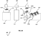
- FIGS 1A and 1B illustrates a schematic view of a system 100 for separating one packaged magnetic material 110 in a plastic bag by means of a flexible rubber platform and feeding the one packaged magnetic material 110 to a packing machine 126.
- the system 100 includes a processor (not shown in FIGS 1A-B ), one or more electromagnetic carrier heads, the one or more bags of packaged magnetic materials 110, a servo motor 112, a cross shaped frame 114, a flexible rubber platform 116, a piston 118, a start sensor 120, a stop sensor 122.
- the one or more electromagnetic carrier heads are a first electromagnetic carrier head 102, a second electromagnetic carrier head 104, a third electromagnetic carrier head 106, and a fourth electromagnetic carrier head 108.
- the first electromagnetic carrier head 102, the second electromagnetic carrier head 104, the third electromagnetic carrier head 106, and the fourth electromagnetic carrier head 108 are configured to pick one bag of packaged magnetic material 110.
- the cross shaped frame 114 is coupled to a rotor of the servo motor 112.
- the first electromagnetic carrier head 102 is coupled to a first axis of the cross shaped frame 114
- the second electromagnetic carrier head 104 is coupled to a second axis of the cross shaped frame 114
- the third electromagnetic carrier head 106 is coupled to a third axis of the cross shaped frame 114
- the fourth electromagnetic carrier head 108 is coupled to a fourth axis of the cross shaped frame 114.
- the bags of packaged magnetic material 110 are packaged screws 130.
- the servo motor 112 is configured to rotate the cross shaped frame 114 at 90° horizontally in clockwise or counter-clockwise direction.
- the flexible rubber platform 116 is adapted to receive the one bag of packaged magnetic materials from a material pouring box 124.
- the centre area of the flexible rubber platform 116 is coated with a formulated paint and rest of the area of the flexible rubber platform 116 is coated with silicon paint.
- the formulated paint defines a high surface friction or tension area.
- the silicon paint coat defines a low surface friction or tension area.
- the high surface friction area is adapted to receive a packaged magnetic material from the plurality of packaged magnetic materials 110.
- the piston 118 is adapted to lift a first packaged magnetic material 110A near to the magnetic field of the first electromagnetic carrier head 102.
- the piston 118 is coupled below the high surface tension area.
- the start sensor 120 is configured to sense the first packaged magnetic material 110A when the piston 118 lifts the first packaged magnetic material 110A from the flexible rubber platform 116 and provides a start signal to the processor.
- the processor energizes the first electromagnetic carrier head 102 to attract at the first packaged magnetic material 110A when the processor receives the start signal.
- the servo motor 112 rotates the cross shaped frame 114 90° horizontally in a clockwise or counter-clockwise direction.
- the stop sensor 122 is configured to provide a stop signal to the processor when the first packaged magnetic material 110A reaches the packaging machine 126.
- the processor de-energizes the first electromagnetic carrier head 102 to drop the first packaged magnetic material or metal 110A in the packaging machine 126 when the processor receives the stop signal.
- the flexible rubber platform 116 is adapted to shrink up and down during the movement of the piston 118.
- the one or more packaged magnetic materials 110 are screws 130 packaged with polypropylene or polyethylene.
- the packaging machine 126 is a shrink packaging machine.
- the first electromagnetic carrier head 102 is configured to pick the first packaged magnetic material 110A from the one or more packaged magnetic material 110.
- the second electromagnetic carrier head 104 is configured to pick a second packaged magnetic material from the one or more packaged magnetic material 110.
- the third electromagnetic carrier head 106 is configured to pick a third packaged magnetic material from the one or more packaged magnetic material 110.
- the fourth electromagnetic carrier head 108 is configured to pick a fourth packaged magnetic material from the one or more packaged magnetic material 110.
- the processor is configured to provide signals to (i) energize the first electromagnetic carrier head 102 to pick the first packaged magnetic material from the flexible rubber platform 116, (ii) de-energize the third electromagnetic carrier head 106 to drop the third packaged magnetic material in the packaging machine 126, and (iii) rotate the cross shaped frame 90° horizontally in a clockwise or counter-clockwise direction simultaneously.
- the processor is configured to provide signals to (i) energize the second electromagnetic carrier head 104 to pick the second packaged magnetic material from the flexible rubber platform 116, (ii) de-energize the fourth electromagnetic carrier head 108 to drop the fourth packaged magnetic material in the packaging machine 126, and (iii) rotate the cross shaped frame 90° horizontally in the clockwise or counter-clockwise direction simultaneously.
- the automation box 128 is adapted to pack the one or more packaged magnetic materials 110 for transportation from one place to another.
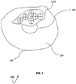
- FIG. 2 illustrates exploded view 200 of the flexible rubber platform 116 of FIGS. 1A-B according to an embodiment herein.
- the flexible rubber platform 116 includes the high surface tension area 202, and the low surface tension area 204.
- the high surface tension area 202 is defined by coating the formulated paint.
- the low surface tension area 204 is defined by coating the silicon paint.
- the low surface tension area 204 is adapted to hold the one or more packaged materials 110 when the piston lifts the first packaged material 110A from the high surface tension area 202.
- the flexible rubber platform 116 is expandable.
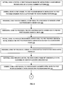
- FIG. 3 is a flow diagram 300 illustrating a method for one or more packaged magnetic materials 110 to a packing machine 126 according to an embodiment herein.
- the method includes following steps.
- step 302 a first packaged magnetic material 110A from a high surface tension area 202 of a flexible rubber platform 116 is lifted using a piston 118.
- the centre part of the flexible rubber platform 116 is coated with a formulated paint and rest of the area of the flexible rubber platform 116 is coated with silicon paint.
- the formulated painted area defines a high surface tension area 202 and silicon painted area defines a low surface tension area 204.
- the first packaged magnetic material 110A is sensed by a start sensor 120, when the first packaged magnetic material 110A is lifted from the flexible rubber platform 116.
- step 306 a start signal is provided to a processor to energize a first electromagnetic carrier head 102 using the start sensor 120.
- step 308 the first electromagnetic carrier head 102 is energized to pick the first packaged magnetic material 110A using the processor.
- the first packaged magnetic material 110A is picked using the first electromagnetic carrier head 102.
- the first electromagnetic carrier head 102 coupled to a cross shaped frame 114.
- a signal is provided to a servo motor 112 using the processor to rotate the cross shaped frame 114.
- the cross shaped frame 114 is rotated 90° horizontally in a clockwise or counter-clockwise direction using the servo motor 112.
- the first packaged magnetic material 110A is sensed by a stop sensor 122 when the first packaged magnetic material 110A reaches the packaging machine 126.
- a stop signal is provided to the processor using the stop sensor 122 to de-energize the first electromagnetic carrier head 102.
- step 320 the first electromagnetic carrier head 102 is de-energized by the processor to drop the first packaged magnetic material 110A in the packaging machine 126.
- the steps from 302 to 320 are repeated for (i) a second electromagnetic carrier head 104, (ii) a third electromagnetic carrier head 106, and (iii) a fourth electromagnetic carrier head 108 to pick a second packaged magnetic material 110B, a third packaged magnetic material 110C, and a fourth packaged magnetic material 110D respectively.
- the cross shaped frame 114 is coupled with (i) the first electromagnetic carrier head 102, (ii) the second electromagnetic carrier head 104, (iii) the third electromagnetic carrier head 106, and (iv) the fourth electromagnetic carrier head 108.
- each electromagnetic carrier head is adapted to pick at least one of the one or more packaged magnetic materials 110.
- the first electromagnetic carrier head 102 is configured to pick the first packaged magnetic material 110A
- the second electromagnetic carrier head 104 is configured to pick the second packaged magnetic material 110B
- the third electromagnetic carrier head is configured to pick the third packaged magnetic material 110C
- the fourth electromagnetic carrier head is configured to pick thte fourth packaged magnetic material 110D.
- the processor is configured to provide signals to (i) energize the first electromagnetic carrier head 102 to pick the first packaged magnetic material 110A from the flexible rubber platform 116, (ii) de-energize the third electromagnetic carrier head 106 to drop the third packaged magnetic material 110C in the packaging machine 126, and (iii) rotate the cross shaped frame 114 90° horizontally in the clockwise or counter-clockwise direction simultaneously.
- the processor is configured to provide signals to (i) energize the second electromagnetic carrier head 104 to pick the second packaged magnetic material 110B from the flexible rubber platform 116, (ii) de-energize the fourth electromagnetic carrier head 108 to drop the fourth packaged magnetic material 110D in the packaging machine 126, and (iii) rotate the cross shaped frame 114 90° horizontally in the clockwise or counter-clockwise direction simultaneously.
- the start sensor 120 and the stop sensor 122 are IR sensors or proximity sensors.
- the invention describes a system, which includes a processor, a servo motor, a flexible rubber platform , the packaged magnetic materials, a piston, electromagnets, a start sensor and a stop sensor.
- the electromagnets pick the packaged magnetic materials from the flexible rubber platform.
- the flexible rubber platform includes a high surface tension area and a low surface tension area.
- the piston is coupled below the high surface tension area and adapted to lift the packaged magnetic material near to the magnetic field of the electromagnets.
- the start sensor provides a start signal to the processor when the piston lifts the packaged magnetic material from the high surface tension area to energize the electromagnets.
- the stop sensor provides a stop signal to the processor when the packaged magnetic material reaches the packaging machine to de-energize the electromagnets to drop the packaged magnetic material in the packaging machine.
Landscapes
- Engineering & Computer Science (AREA)
- Mechanical Engineering (AREA)
- Feeding Of Articles To Conveyors (AREA)
Priority Applications (1)
| Application Number | Priority Date | Filing Date | Title |
|---|---|---|---|
| EP17173076.5A EP3406548A1 (fr) | 2017-05-26 | 2017-05-26 | Système et procédé pour séparer et acheminer un paquet de matériaux magnétiques vers une machine d'emballage |
Applications Claiming Priority (1)
| Application Number | Priority Date | Filing Date | Title |
|---|---|---|---|
| EP17173076.5A EP3406548A1 (fr) | 2017-05-26 | 2017-05-26 | Système et procédé pour séparer et acheminer un paquet de matériaux magnétiques vers une machine d'emballage |
Publications (1)
| Publication Number | Publication Date |
|---|---|
| EP3406548A1 true EP3406548A1 (fr) | 2018-11-28 |
Family
ID=59009516
Family Applications (1)
| Application Number | Title | Priority Date | Filing Date |
|---|---|---|---|
| EP17173076.5A Withdrawn EP3406548A1 (fr) | 2017-05-26 | 2017-05-26 | Système et procédé pour séparer et acheminer un paquet de matériaux magnétiques vers une machine d'emballage |
Country Status (1)
| Country | Link |
|---|---|
| EP (1) | EP3406548A1 (fr) |
Citations (9)
| Publication number | Priority date | Publication date | Assignee | Title |
|---|---|---|---|---|
| US3448857A (en) | 1966-10-24 | 1969-06-10 | Eriez Magnetics | Electrodynamic separator |
| US3709385A (en) * | 1971-08-05 | 1973-01-09 | Delta Eng Corp | Parts conveyor |
| GB1356486A (en) | 1972-01-19 | 1974-06-12 | Metal Box Co Ltd | Article transfer apparatus |
| FR2267266A1 (en) * | 1974-04-10 | 1975-11-07 | Glotter Metall Gmbh Et Co | Selector presenting individual fruits without bruising - for cutting prior to removal of stones |
| JPS52137482U (fr) * | 1976-04-13 | 1977-10-19 | ||
| JPH09156773A (ja) * | 1995-12-05 | 1997-06-17 | Olympus Optical Co Ltd | 部品供給装置 |
| EP1947036A1 (fr) * | 2007-01-19 | 2008-07-23 | komax Holding AG | Dispositif de séparation pour petites pièces et procédé de séparation de petites pièces |
| CN102897494A (zh) | 2012-08-29 | 2013-01-30 | 长城汽车股份有限公司 | 一种螺栓输送装置 |
| CN105752683A (zh) * | 2016-04-27 | 2016-07-13 | 福建师范大学福清分校 | 一种流水线托盘的自动捡装系统 |
-
2017
- 2017-05-26 EP EP17173076.5A patent/EP3406548A1/fr not_active Withdrawn
Patent Citations (9)
| Publication number | Priority date | Publication date | Assignee | Title |
|---|---|---|---|---|
| US3448857A (en) | 1966-10-24 | 1969-06-10 | Eriez Magnetics | Electrodynamic separator |
| US3709385A (en) * | 1971-08-05 | 1973-01-09 | Delta Eng Corp | Parts conveyor |
| GB1356486A (en) | 1972-01-19 | 1974-06-12 | Metal Box Co Ltd | Article transfer apparatus |
| FR2267266A1 (en) * | 1974-04-10 | 1975-11-07 | Glotter Metall Gmbh Et Co | Selector presenting individual fruits without bruising - for cutting prior to removal of stones |
| JPS52137482U (fr) * | 1976-04-13 | 1977-10-19 | ||
| JPH09156773A (ja) * | 1995-12-05 | 1997-06-17 | Olympus Optical Co Ltd | 部品供給装置 |
| EP1947036A1 (fr) * | 2007-01-19 | 2008-07-23 | komax Holding AG | Dispositif de séparation pour petites pièces et procédé de séparation de petites pièces |
| CN102897494A (zh) | 2012-08-29 | 2013-01-30 | 长城汽车股份有限公司 | 一种螺栓输送装置 |
| CN105752683A (zh) * | 2016-04-27 | 2016-07-13 | 福建师范大学福清分校 | 一种流水线托盘的自动捡装系统 |
Similar Documents
| Publication | Publication Date | Title |
|---|---|---|
| US12297058B2 (en) | Vision-assisted robotized depalletizer | |
| US9828192B2 (en) | Conveying arrangement | |
| CN108698089B (zh) | 一种自动分拣系统及自动分拣机器人 | |
| CN210753836U (zh) | 末端执行器、机器人和货物分拣系统 | |
| CN203911809U (zh) | 电粘附抓取系统 | |
| EP2337757B1 (fr) | Dispositif d'alimentation pour robots, moyens d'automatisation et autres | |
| US11911894B2 (en) | Method and system for manipulating articles | |
| NL2010272C2 (en) | Container sleeving method and system for fixing a sleeve around a container. | |
| FI3858768T3 (fi) | Menetelmä pinottavien kappaletavarapakkausten purkamiseksi lavalta | |
| JP2013504503A5 (fr) | ||
| CN104850117B (zh) | 一种机器人自动化生产线实验平台及其控制方法 | |
| EP3541729A1 (fr) | Système de déchargement de colis automatisé | |
| US20210047115A1 (en) | Robot system for gripping an item in a storage and picking system, and operating method for same | |
| KR20200001162A (ko) | 초소형 물품 자동 분류 시스템 | |
| EP4051459B1 (fr) | Appareil modulaire pour le remplissage et la fermeture d'articles, installation et procédé | |
| CN110217424A (zh) | 一种用于泡椒鸡爪理料装箱机构 | |
| CN112278358B (zh) | 一种药品包装自动化控制实训系统 | |
| WO2015112018A1 (fr) | Unité de préhension permettant de saisir, de soulever, de transporter et de décharger des boîtes | |
| CN105339285A (zh) | 用于将设置成堆垛的物品卸垛和运送的设备和方法 | |
| EP3406548A1 (fr) | Système et procédé pour séparer et acheminer un paquet de matériaux magnétiques vers une machine d'emballage | |
| CN110834958A (zh) | 一种农产品包装盒的自动码垛系统 | |
| US20230116557A1 (en) | Device for taking hold of and releasing an object | |
| CN114802931A (zh) | 具有精准计数理料功能的套装包装机 | |
| US20040070226A1 (en) | Gripping members gripping and moving packets stacked by a conveyor | |
| WO2025082593A1 (fr) | Système de déchargement pour déchargement automatique d'un objet |
Legal Events
| Date | Code | Title | Description |
|---|---|---|---|
| PUAI | Public reference made under article 153(3) epc to a published international application that has entered the european phase |
Free format text: ORIGINAL CODE: 0009012 |
|
| STAA | Information on the status of an ep patent application or granted ep patent |
Free format text: STATUS: THE APPLICATION HAS BEEN PUBLISHED |
|
| AK | Designated contracting states |
Kind code of ref document: A1 Designated state(s): AL AT BE BG CH CY CZ DE DK EE ES FI FR GB GR HR HU IE IS IT LI LT LU LV MC MK MT NL NO PL PT RO RS SE SI SK SM TR |
|
| AX | Request for extension of the european patent |
Extension state: BA ME |
|
| STAA | Information on the status of an ep patent application or granted ep patent |
Free format text: STATUS: REQUEST FOR EXAMINATION WAS MADE |
|
| 17P | Request for examination filed |
Effective date: 20190523 |
|
| RBV | Designated contracting states (corrected) |
Designated state(s): AL AT BE BG CH CY CZ DE DK EE ES FI FR GB GR HR HU IE IS IT LI LT LU LV MC MK MT NL NO PL PT RO RS SE SI SK SM TR |
|
| GRAP | Despatch of communication of intention to grant a patent |
Free format text: ORIGINAL CODE: EPIDOSNIGR1 |
|
| STAA | Information on the status of an ep patent application or granted ep patent |
Free format text: STATUS: GRANT OF PATENT IS INTENDED |
|
| RIC1 | Information provided on ipc code assigned before grant |
Ipc: B65G 47/14 20060101AFI20220309BHEP |
|
| INTG | Intention to grant announced |
Effective date: 20220329 |
|
| STAA | Information on the status of an ep patent application or granted ep patent |
Free format text: STATUS: THE APPLICATION IS DEEMED TO BE WITHDRAWN |
|
| 18D | Application deemed to be withdrawn |
Effective date: 20220809 |