EP3406552A1 - Instrument de fixation de film protecteur - Google Patents
Instrument de fixation de film protecteur Download PDFInfo
- Publication number
- EP3406552A1 EP3406552A1 EP16886639.0A EP16886639A EP3406552A1 EP 3406552 A1 EP3406552 A1 EP 3406552A1 EP 16886639 A EP16886639 A EP 16886639A EP 3406552 A1 EP3406552 A1 EP 3406552A1
- Authority
- EP
- European Patent Office
- Prior art keywords
- protective film
- receiving groove
- release paper
- cover
- case
- Prior art date
- Legal status (The legal status is an assumption and is not a legal conclusion. Google has not performed a legal analysis and makes no representation as to the accuracy of the status listed.)
- Withdrawn
Links
Images












Classifications
-
- B—PERFORMING OPERATIONS; TRANSPORTING
- B65—CONVEYING; PACKING; STORING; HANDLING THIN OR FILAMENTARY MATERIAL
- B65H—HANDLING THIN OR FILAMENTARY MATERIAL, e.g. SHEETS, WEBS, CABLES
- B65H37/00—Article or web delivery apparatus incorporating devices for performing specified auxiliary operations
- B65H37/04—Article or web delivery apparatus incorporating devices for performing specified auxiliary operations for securing together articles or webs, e.g. by adhesive, stitching or stapling
-
- A—HUMAN NECESSITIES
- A45—HAND OR TRAVELLING ARTICLES
- A45C—PURSES; LUGGAGE; HAND CARRIED BAGS
- A45C11/00—Receptacles for purposes not provided for in groups A45C1/00-A45C9/00
-
- B—PERFORMING OPERATIONS; TRANSPORTING
- B32—LAYERED PRODUCTS
- B32B—LAYERED PRODUCTS, i.e. PRODUCTS BUILT-UP OF STRATA OF FLAT OR NON-FLAT, e.g. CELLULAR OR HONEYCOMB, FORM
- B32B37/00—Methods or apparatus for laminating, e.g. by curing or by ultrasonic bonding
- B32B37/0007—Methods or apparatus for laminating, e.g. by curing or by ultrasonic bonding involving treatment or provisions in order to avoid deformation or air inclusion, e.g. to improve surface quality
- B32B37/003—Methods or apparatus for laminating, e.g. by curing or by ultrasonic bonding involving treatment or provisions in order to avoid deformation or air inclusion, e.g. to improve surface quality to avoid air inclusion
-
- B—PERFORMING OPERATIONS; TRANSPORTING
- B29—WORKING OF PLASTICS; WORKING OF SUBSTANCES IN A PLASTIC STATE IN GENERAL
- B29C—SHAPING OR JOINING OF PLASTICS; SHAPING OF MATERIAL IN A PLASTIC STATE, NOT OTHERWISE PROVIDED FOR; AFTER-TREATMENT OF THE SHAPED PRODUCTS, e.g. REPAIRING
- B29C63/00—Lining or sheathing, i.e. applying preformed layers or sheathings of plastics; Apparatus therefor
- B29C63/02—Lining or sheathing, i.e. applying preformed layers or sheathings of plastics; Apparatus therefor using sheet or web-like material
-
- B—PERFORMING OPERATIONS; TRANSPORTING
- B32—LAYERED PRODUCTS
- B32B—LAYERED PRODUCTS, i.e. PRODUCTS BUILT-UP OF STRATA OF FLAT OR NON-FLAT, e.g. CELLULAR OR HONEYCOMB, FORM
- B32B37/00—Methods or apparatus for laminating, e.g. by curing or by ultrasonic bonding
- B32B37/0046—Methods or apparatus for laminating, e.g. by curing or by ultrasonic bonding characterised by constructional aspects of the apparatus
-
- B—PERFORMING OPERATIONS; TRANSPORTING
- B65—CONVEYING; PACKING; STORING; HANDLING THIN OR FILAMENTARY MATERIAL
- B65H—HANDLING THIN OR FILAMENTARY MATERIAL, e.g. SHEETS, WEBS, CABLES
- B65H37/00—Article or web delivery apparatus incorporating devices for performing specified auxiliary operations
- B65H37/02—Article or web delivery apparatus incorporating devices for performing specified auxiliary operations for applying adhesive
-
- C—CHEMISTRY; METALLURGY
- C09—DYES; PAINTS; POLISHES; NATURAL RESINS; ADHESIVES; COMPOSITIONS NOT OTHERWISE PROVIDED FOR; APPLICATIONS OF MATERIALS NOT OTHERWISE PROVIDED FOR
- C09J—ADHESIVES; NON-MECHANICAL ASPECTS OF ADHESIVE PROCESSES IN GENERAL; ADHESIVE PROCESSES NOT PROVIDED FOR ELSEWHERE; USE OF MATERIALS AS ADHESIVES
- C09J7/00—Adhesives in the form of films or foils
-
- G—PHYSICS
- G02—OPTICS
- G02F—OPTICAL DEVICES OR ARRANGEMENTS FOR THE CONTROL OF LIGHT BY MODIFICATION OF THE OPTICAL PROPERTIES OF THE MEDIA OF THE ELEMENTS INVOLVED THEREIN; NON-LINEAR OPTICS; FREQUENCY-CHANGING OF LIGHT; OPTICAL LOGIC ELEMENTS; OPTICAL ANALOGUE/DIGITAL CONVERTERS
- G02F1/00—Devices or arrangements for the control of the intensity, colour, phase, polarisation or direction of light arriving from an independent light source, e.g. switching, gating or modulating; Non-linear optics
- G02F1/01—Devices or arrangements for the control of the intensity, colour, phase, polarisation or direction of light arriving from an independent light source, e.g. switching, gating or modulating; Non-linear optics for the control of the intensity, phase, polarisation or colour
-
- G—PHYSICS
- G06—COMPUTING OR CALCULATING; COUNTING
- G06F—ELECTRIC DIGITAL DATA PROCESSING
- G06F1/00—Details not covered by groups G06F3/00 - G06F13/00 and G06F21/00
- G06F1/16—Constructional details or arrangements
- G06F1/1613—Constructional details or arrangements for portable computers
- G06F1/1626—Constructional details or arrangements for portable computers with a single-body enclosure integrating a flat display, e.g. Personal Digital Assistants [PDAs]
-
- H—ELECTRICITY
- H04—ELECTRIC COMMUNICATION TECHNIQUE
- H04B—TRANSMISSION
- H04B1/00—Details of transmission systems, not covered by a single one of groups H04B3/00 - H04B13/00; Details of transmission systems not characterised by the medium used for transmission
- H04B1/38—Transceivers, i.e. devices in which transmitter and receiver form a structural unit and in which at least one part is used for functions of transmitting and receiving
- H04B1/3827—Portable transceivers
- H04B1/3888—Arrangements for carrying or protecting transceivers
-
- A—HUMAN NECESSITIES
- A45—HAND OR TRAVELLING ARTICLES
- A45C—PURSES; LUGGAGE; HAND CARRIED BAGS
- A45C11/00—Receptacles for purposes not provided for in groups A45C1/00-A45C9/00
- A45C11/002—Receptacles for purposes not provided for in groups A45C1/00-A45C9/00 for storing portable handheld communication devices, e.g. pagers or smart phones
-
- A—HUMAN NECESSITIES
- A45—HAND OR TRAVELLING ARTICLES
- A45C—PURSES; LUGGAGE; HAND CARRIED BAGS
- A45C11/00—Receptacles for purposes not provided for in groups A45C1/00-A45C9/00
- A45C11/003—Receptacles for purposes not provided for in groups A45C1/00-A45C9/00 for storing portable computing devices, e.g. laptops, tablets or calculators
-
- A—HUMAN NECESSITIES
- A45—HAND OR TRAVELLING ARTICLES
- A45C—PURSES; LUGGAGE; HAND CARRIED BAGS
- A45C2200/00—Details not otherwise provided for in A45C
- A45C2200/10—Transparent walls
-
- B—PERFORMING OPERATIONS; TRANSPORTING
- B29—WORKING OF PLASTICS; WORKING OF SUBSTANCES IN A PLASTIC STATE IN GENERAL
- B29C—SHAPING OR JOINING OF PLASTICS; SHAPING OF MATERIAL IN A PLASTIC STATE, NOT OTHERWISE PROVIDED FOR; AFTER-TREATMENT OF THE SHAPED PRODUCTS, e.g. REPAIRING
- B29C63/00—Lining or sheathing, i.e. applying preformed layers or sheathings of plastics; Apparatus therefor
- B29C63/0004—Component parts, details or accessories; Auxiliary operations
- B29C2063/0008—Registering, centering the lining material on the substrate
-
- B—PERFORMING OPERATIONS; TRANSPORTING
- B29—WORKING OF PLASTICS; WORKING OF SUBSTANCES IN A PLASTIC STATE IN GENERAL
- B29C—SHAPING OR JOINING OF PLASTICS; SHAPING OF MATERIAL IN A PLASTIC STATE, NOT OTHERWISE PROVIDED FOR; AFTER-TREATMENT OF THE SHAPED PRODUCTS, e.g. REPAIRING
- B29C63/00—Lining or sheathing, i.e. applying preformed layers or sheathings of plastics; Apparatus therefor
- B29C63/02—Lining or sheathing, i.e. applying preformed layers or sheathings of plastics; Apparatus therefor using sheet or web-like material
- B29C2063/027—Lining or sheathing, i.e. applying preformed layers or sheathings of plastics; Apparatus therefor using sheet or web-like material applied by a squeegee
-
- B—PERFORMING OPERATIONS; TRANSPORTING
- B65—CONVEYING; PACKING; STORING; HANDLING THIN OR FILAMENTARY MATERIAL
- B65H—HANDLING THIN OR FILAMENTARY MATERIAL, e.g. SHEETS, WEBS, CABLES
- B65H2301/00—Handling processes for sheets or webs
- B65H2301/50—Auxiliary process performed during handling process
- B65H2301/51—Modifying a characteristic of handled material
- B65H2301/516—Securing handled material to another material
- B65H2301/5161—Binding processes
-
- C—CHEMISTRY; METALLURGY
- C09—DYES; PAINTS; POLISHES; NATURAL RESINS; ADHESIVES; COMPOSITIONS NOT OTHERWISE PROVIDED FOR; APPLICATIONS OF MATERIALS NOT OTHERWISE PROVIDED FOR
- C09J—ADHESIVES; NON-MECHANICAL ASPECTS OF ADHESIVE PROCESSES IN GENERAL; ADHESIVE PROCESSES NOT PROVIDED FOR ELSEWHERE; USE OF MATERIALS AS ADHESIVES
- C09J2203/00—Applications of adhesives in processes or use of adhesives in the form of films or foils
-
- G—PHYSICS
- G06—COMPUTING OR CALCULATING; COUNTING
- G06F—ELECTRIC DIGITAL DATA PROCESSING
- G06F2200/00—Indexing scheme relating to G06F1/04 - G06F1/32
- G06F2200/16—Indexing scheme relating to G06F1/16 - G06F1/18
- G06F2200/163—Indexing scheme relating to constructional details of the computer
- G06F2200/1634—Integrated protective display lid, e.g. for touch-sensitive display in handheld computer
Definitions
- Exemplary embodiments of the invention relate to a protective film attaching apparatus for attaching a protective film to a display area of a portable electronic apparatus.
- a protective film is used to protect a display panel of a portable electronic apparatus such as a mobile phone or tablet PC from damage or scratch.
- the protective film which is not properly attached on the display panel may cause degradation of visibility of the display panel, and may disturb touch operation of a user.
- rework of attaching the protective film to correct the defect may decrease visibility of the display panel and adhesion of the protective film due to contamination of the protective film.
- One or more exemplary embodiment of the invention provides a protective film attaching apparatus capable of easy attachment of a protective film to a display area of a portable electronic apparatus.
- a protective film attaching apparatus includes a case having a first receiving groove configured to receive a rear surface of a portable electronic apparatus, a cover having a second receiving groove configured to receive a front surface of the portable electronic apparatus, and formed at a side of the case configured to rotate for opening or closing the case, the second receiving groove being corresponding to the fist receiving groove, and a film member provided in the second receiving groove.
- the protective film attaching apparatus may further include a folding line which is formed from the first extending groove to the second extending groove through the second receiving groove.
- the cover has a first extending groove formed from an upper edge of the cover to an upper portion of the second receiving groove, and a second extending groove formed from a lower edge of the cover to a lower portion of the second receiving groove.
- a through hole may be formed through a bottom surface of the second receiving groove, a pair of adhesive tape to support the film member may be attached on the both side of the through hole, respectively.
- the cover may include a stepped portion formed at both side of the through hole in a width direction. Boundary of the film member may be received in the second receiving groove with spaced apart from the stepped portion by a predetermined gap.
- the film member may include a protective film and a first release paper attached on a front surface of the protective film.
- the first release paper may be removed from the protective film when the adhesive tape is removed.
- he protective film attaching apparatus may further include an incision portion having predetermined width and length from an upper edge of the cover to the second receiving groove configured to expose an upper portion of the film member when the case is combined with the cover.
- the film member may include a protective film received in the second receiving groove, a first release paper attached on a front surface of the protective film, and a second release paper attached on a rear surface of the protective film.
- the film member may include a first grip tape attached on an upper side portion of the first release paper and a second grip tape attached on an upper side portion of the second release paper.
- the first grip tape may be protruded from the first release paper
- the second grip tape is protruded from the second release paper.
- a grip tape receiving groove may be formed at an upper portion of the second receiving groove to receive the second grip tape.
- the protective film attaching apparatus may further include at least one or more of guide protrusion and guide groove for guiding a combination direction.
- the guide protrusion and guide groove may be formed at facing surfaces of the case and the cover, respectively.
- a protective film attaching apparatus includes a case having a receiving groove configured to receive a rear surface of a portable electronic apparatus, a cover having a through hole corresponding to the receiving groove, and formed at a side of the case configured to rotate for opening or closing the case, and a film member facing the front surface of the portable electronic apparatus through the through hole. A boundary of the film member is attached along a boundary of the through hole.
- the protective film attaching apparatus may further include a stepped portion formed along the boundary of the through hole on a front surface of the cover. The film member is attached along the stepped portion.
- the film member may include a first release paper, a protective film attached on a surface of the first release paper, and a second release paper attached on a surface of the protective film.
- a boundary of the first release paper may be attached along the along the stepped portion.
- a protective film attaching apparatus includes a case having a first receiving groove configured to receive a rear surface of a portable electronic apparatus, a cover formed at a side of the case configured to rotate for opening or closing the case, and a film member provided at the cover configured to face the portable electronic apparatus.
- the case has a protrusion part formed inner side of the case, and the first receiving groove is depressed on the protrusion part.
- the protrusion part may include a first protrusion part and a second protrusion part which form a stepped portion.
- the second protrusion may include a second receiving groove to receive the second protrusion part formed inner side of the cover.
- the second protrusion part may be inserted into the second receiving groove when the case is combined with the cover.
- the case may have a first gripping groove formed at a side of the protrusion part.
- the cover may have a through hole formed at a bottom surface of the second receiving groove.
- the film member may include a protective film received in the through hole, a first release paper attached on a rear surface of the protective film, and a second release paper attached on a front surface of the protective film and on a boundary of the through hole.
- the first release paper may include a first-first release paper attached on an upper portion of the protective film, and a first-second release paper attached on the other portion of the protective film.
- the second release paper may include at least one or more of locking hole formed along a boundary of the second release paper. At least one or more of locking protrusion corresponding to the locking hole may be formed on a front surface of the cover configured to be combined with the locking hole.
- the film member further include grip tapes attached on each of the first release paper and the second release paper.
- the protective film attaching apparatus of the present invention rather than general public is also a trained technician can easily attach the protective film on the front display area of the portable electronic apparatus.
- the protective film may be attached on a correct position with our bubbles, so that cost and time may be saved due to repurchase and rework when the attachment is failed.
- 'front' means front side of the portable electronic apparatus which a display area of the portable electronic apparatus with a case is exposed
- 'rear' means rear side of the portable electronic apparatus which is opposite to the front of the portable electronic apparatus.
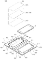
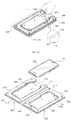
- the protective film attaching apparatus 100 includes a case 200 which receives a portable electronic apparatus 10, a cover 400 for opening the case 200, and a film member 500 configured to applied to a front display area of the portable electronic apparatus 10.
- the film member 500 is received in the cover 400.
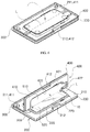
- a case 200 may be formed of synthetic resin with small thickness, and may have a first protrusion part 210, and a first receiving groove 220.
- the first protrusion part 210 is protruded frontward with a predetermined height.
- the first receiving groove 220 is depressed rearward from a surface of the first protrusion part 210.
- a first flange portion 230 may be formed outward along a boundary of the first protrusion part 210 with a predetermined width.
- At least one or more of guide protrusions 211 may be formed on the first protrusion part 210.
- the guide protrusions 211 are spaced apart from each other.
- the guide protrusion 211 is inserted into a guide groove 411 of the cover 400 when the case 200 is combined with the cover 400, so that the guide protrusions 211 may guide combination of the case 200 and the cover 400.
- a combining protrusion 212 may be formed on the first protrusion part 210.
- the combining protrusion 212 may be inserted into a combining groove 412 of the cover 400 when the case 200 is combined with the cover 400.
- the guide protrusion 211 may be formed on the cover 400, and the guide groove 411 may be formed on the case 200.
- the combining protrusion 212 may be formed on the cover 400, and the combining groove 412 may be formed on the case 200.
- a rear surface of the portable electronic apparatus 10 is received in the first receiving groove 220.
- a lens part receiving groove 221 may be formed at a portion of the first receiving groove 220.
- the lens part receiving groove 221 may be formed at an upper portion of the first receiving groove 220.
- a gripping groove 222 for removing the portable electronic apparatus 10 may be formed at another portion of the first receiving groove 220.
- the gripping groove 222 may be formed at a lower portion of the first receiving groove 220.
- a first operation button groove 223 which is corresponding to an operation button at a side surface of the portable electronic apparatus 10 may be formed at an edge of the first receiving groove 220.
- a connecting part 300 having a predetermined width is formed from the first flange portion 230 of the case 200, and the cover 400 is connected to the connecting part 300.
- the case 200, the cover 400 and the connecting part 300 may be integrally formed.
- the case 200 and the cover 400 may be mutually rotated about the connecting portion 300.
- folding lines (not shown) along a length direction may be formed at both sides of the connecting part 300 in a width direction.
- the folding line may be a concave groove along the length direction.
- the folding line may be a dot lines which has a plurality of concave grooves spaced apart by the length direction, or a break line.
- the cover 400 is formed opposite to the case 200 with respect to the connecting part 300.
- the cover 400 may be folded along the folding line of the connecting part 300, so that the cover 400 may open and close a front of the case 200.
- the cover 400 may include a second protrusion part 410 on a rear surface which faces the first protrusion par 210 of the case 200 and a second receiving groove 420.
- the second protrusion part 410 is protruded rearward with a predetermined height.
- the second receiving groove 420 is depressed frontward from a surface of the second protrusion part 410.
- a second flange portion 430 may be formed outward along a boundary of the second protrusion part 410 with a predetermined width.
- At least one or more of guide grooves 411 may be formed on the second protrusion part 410.
- the guide grooves 411 are spaced apart from each other.
- the guide groove 411 is inserted into a guide protrusion 211 of the case 200 when the case 200 is combined with the cover 400, so that the guide grooves 411 may guide combination of the case 200 and the cover 400.
- a combining groove 412 may be formed on the second protrusion part 410 corresponding to the combining protrusion 212 which is mentioned above.
- a front face of the portable electronic apparatus 10 is received in the second receiving groove 420.
- a second operation button groove 421 may be formed at an edge of the second receiving groove 420.
- the first operation button groove 223 which is mentioned above and the second operation button groove 421 may receive the operation button together.
- a folding line L is formed from an upper edge of the cover 400 to lower edge of the cover 400 configured to fold the cover 400 in a width direction.
- a first extending groove 440 is extended from the upper edge of the cover 400 to an upper portion of the second receiving groove 420.
- a second extending groove 450 is extended from the lower edge of the cover 400 to a lower portion of the second receiving groove 420.
- the folding line L straightly extends from the first extending groove 440 to the second extending groove 450 through the second receiving groove 420.
- a rear surface of the second flange portion 430, a bottom surface of the first extending groove 440, a bottom surface of the second receiving groove 420 and a bottom surface of the second extending groove 450 may preferably be disposed at a same plane.
- An adhesive 460 may be provided on each of corner portions of the bottom surface of the second receiving groove 420.
- the adhesive 460 may be a double-faced pressure sensitive adhesive film or tape.
- the film member 500 may be received in the second receiving groove 420.
- the film member 500 includes a first release paper 510 which is attached to the bottom surface of the second receiving groove 420 by the adhesive 460, a protective film 520 which is attached to a rear surface of the first release paper 510, and a second release paper 530 which is attached to a rear surface of the protective film 520.
- the first release paper 510 is attached on a front surface of the protective film 520
- the second release paper 530 is attached on a rear surface of the protective film 520
- a front surface of the first release paper 510 is attached on the bottom surface of the second receiving groove 420 by the adhesive 460.
- an adhesive layer is formed on the rear surface of the protective film 520 to firmly attach the protective film 520 on the display area of the portable electronic apparatus 10, the protective film 520 may be formed by tempered glass.
- a first grip tape (refers to 511 of FIG. 9 ) may be formed upper side portion of the first release paper 510.
- the first grip tape 511 may be integrally formed with the first release paper 510, or an additional first grip tape 511 may be attached on the first release paper 510.
- the additional first grip tape 511 is attached on the first release paper 510, a first end of the first grip tape 511 is attached to the upper side of the first release paper 510, and a second end of the first release paper 510 is protruded toward upper outer direction.
- a second grip tape 531 may be integrally formed with the second release paper 530, or an additional second grip tape 531 may be attached on the second release paper 530 at a upper side of the to easily remove the second release paper 530 from the protective film 520.
- a grip tape receiving groove 422 may be formed at an upper side of the second receiving groove 420 to receive protruded portion of the first grip tape 511 and the second grip tape 531.
- the protective film attaching apparatus 100 is provided with a film member 500 in the second receiving groove 420 and the case 200 which is combined with the cover 400.
- the case 200 may be opened if necessary.
- additional film member 500 may be separately purchased, and then the film member 500 may be attached on the second receiving groove 420, so that protective film attaching apparatus 100 may be reusable.
- the cover 400 is disunited from the case 200, the portable electronic apparatus 10 is received in the first receiving groove 220 of the case 200 configured to expose the front surface of the portable electronic apparatus 10.
- the second release paper 530 is removed from the film member 500 in the second receiving groove 420 of the cover 400 to expose adhesive surface of the protective film 520.
- the cover 400 is rotated to be combined with the case 200.
- the guide protrusions 211 is inserted into the guide groove 411, and the combining protrusion 212 is inserted into the combining groove 412.
- front of the cover 400 is pressed or rubbed to apply the protective film 520 on front display area of the portable electronic apparatus 10.
- the cover 400 is folded frontward along the folding line L of the cover 400.
- another portion of the cover 400 is fixed because the combining protrusion is inserted in the combining groove 412.
- the protective film 520 is attached on the front display area of the portable electronic apparatus 10.
- the first release paper 510 which is attached on the adhesive in the second receiving groove 420 is folded with the cover 400 which is folded, so that first release paper 510 is removed from the protective film 520.
- the other portion of the cover 400 is rotated to disunite from the case 200, remained portion of the first release paper 510 which is remained on the protective film 520 is totally removed from the protective film 520. And then user may finish attachment of the protective film 520 by rubbing or pressing front surface of the protective film 520.
- the portable electronic apparatus 10 may be removed from the first receiving groove 220. If another attachment is necessary, the first release paper 510 may be removed from the second receiving groove 420, and then an additional film member 500 may be purchased and attached in the second receiving groove 420, and then the above process may be repeated.
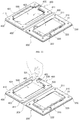
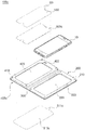
- the protective film attaching apparatus 100a includes a case 200, a cover 400 and a film member 500 like the first embodiment, but the protective film attaching apparatus 100a has a through hole 423 formed at a bottom surface of the second receiving groove 420, a stepped portion 424 which is formed at both sides of the second receiving groove 420 in a width direction, and a pair of adhesive tapes which support the film member 500.
- the protective film attaching apparatus 100a does not have a folding line L in the second receiving groove 420 of the cover 400.
- the through hole 423 is formed at the bottom surface of the second receiving groove 420 of the cover 400.
- the stepped portions 424 are formed at the rear surface of the cover 400. Both sides of the second receiving groove 420 is extended outward with a predetermined width, so that each of the stepped portions 424 is formed at each of both sides of the through hole 423 in a width direction.
- the film member 500 is received in the second receiving groove 420.
- width and length of the through hole 423 is larger than width and length of the film member 500.
- a pair of adhesive tapes 600 is attached to both sides of the film member 500 in a width direction, respectively to prevent departure of the film member 500 from the through hole 423.
- a side of the adhesive tape 600 is attached to a side of the film member 500 in a width direction.
- Another side of the adhesive tape 600 is attached to a front surface of the cover 400 corresponding to the stepped portion 424.
- the film member 500 is supported by the adhesive tape 600 in the through hole 423 with being spaced apart from the stepped portion 424.
- an additional guide jig (not shown) for attaching the adhesive tape 600 may be used when the adhesive tape 600 is attached.
- the guide jig has a shape corresponding to the second receiving groove 420, and includes a body which is inserted into the second receiving groove 420, and a pair of wing parts which is protruded from both side of the body in a width direction to support the stepped portion 424.
- a locking jaw is formed at an upper portion of the body and along boundary of the body. A Edge of the through hole 423 is supported by the locking jaw when the body of the guide jig is inserted into the second receiving groove 420.
- the film member 500 When the film member 500 is received in, an edge of the film member 500 is supported by the inner portion of the locking jaw. Thus, the film member 500 is properly located, and then one side of the adhesive tape 600 is attached on the film member 500, and then the other side of the adhesive tape 600 is attached on the front surface of the cover 400 corresponding to the stepped portion 424.
- the protective film attaching apparatus 100a is provided with the film member 500 in the second receiving groove 420 and the case 200 which is combined with the cover 400.
- the case 200 may be opened if necessary.
- additional film member 500 may be separately purchased, and then the film member 500 may be attached on the second receiving groove 420, so that protective film attaching apparatus 100a may be reusable.
- the cover 400 is disunited from the case 200, the portable electronic apparatus 10 is received in the first receiving groove 220 of the case 200 configured to expose the front surface of the portable electronic apparatus 10.
- the second release paper 530 is removed from the film member 500 in the second receiving groove 420 of the cover 400 to expose adhesive surface of the protective film 520.
- the cover 400 is rotated to be combined with the case 200.
- the guide protrusions 211 is inserted into the guide groove 411.
- additional combining protrusion and combining groove for combination are formed like the first embodiment.
- the first release paper 510 is removed from the protective film 520 through the through hole 423.
- the adhesive tape 600 which is attached on both sides of the second release paper 530 in a width direction is removed with the second release paper 530.
- the cover 400 is opened, and then the portable electronic apparatus 10 on which the protective film 520 is attached is separated from the first receiving groove 220. Attachment process of the protective film 520 is finished or the portable electronic apparatus 10 can be used.
- an additional film member 500 may be purchased and received in the through hole 423 using the adhesive tape 600, and then the above process may be repeated.
- the guide jig which is mentioned above may be used to properly locate the film member 500.
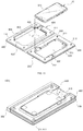
- the protective film attaching apparatus 100b according to the third embodiment includes a case 200, a cover 400 and a film member 500 like the first embodiment, but unlike the fir embodiment, the protective film attaching apparatus 100b does not have a folding line L in the second receiving groove 420 of the cover 400, the protective film attaching apparatus 100b has an incision portion 470 is formed at an upper portion of the second receiving groove 420.
- the incision portion 470 is formed from an upper edge of the cover 400 to an upper portion of the second receiving groove 420 with predetermined width and length. Accordingly, when the case 200 and the cover 400 are combined with each other, an upper portion of the film member 500 is exposed through the incision portion 470 of a front surface of the cover 400. User may remove the first release paper 510 from the protective film 520 by opening the cover 400 with pressing the upper portion of the protective film 520 through the incision portion 470 after attachment of the protective film 520.
- the protective film attaching apparatus 100b is provided with the film member 500 in the second receiving groove 420 and the case 200 which is combined with the cover 400.
- the case 200 may be opened if necessary.
- additional film member 500 may be separately purchased, and then the film member 500 may be attached on the second receiving groove 420, so that protective film attaching apparatus 100 may be reusable.
- the cover 400 is disunited from the case 200, the portable electronic apparatus 10 is received in the first receiving groove 220 of the case 200 configured to expose the front surface of the portable electronic apparatus 10.
- the second release paper 530 is removed from the film member 500 in the second receiving groove 420 of the cover 400 to expose adhesive surface of the protective film 520.
- the cover 400 is rotated to be combined with the case 200.
- the guide protrusions 211 is inserted into the guide groove 411.
- additional combining protrusion and combining groove for combination are formed like the first embodiment.
- the cover 400 is opened with pressing the upper portion of the protective film 520.
- the protective film 520 is remained on the display area of the portable electronic apparatus 10, and the first release paper 510 on the second receiving groove 420 is rotated with the cover 400, so that the first release paper 510 is removed from the protective film 520.
- the cover 400 is opened, and then the portable electronic apparatus 10 on which the protective film 520 is attached is separated from the first receiving groove 220. Attachment process of the protective film 520 is finished or the portable electronic apparatus 10 can be used.
- the first release paper 510 may be removed from the second receiving groove 420, and then an additional film member 500 may be purchased and attached in the second receiving groove 420, and then the above process may be repeated.
- the protective film attaching apparatus 100c according to the fourth embodiment includes a case 200, a cover 400c and a film member 500c like the first embodiment, but the cover 400c has a plate shape, a through hole 423 is formed at the cover 400c, and edges of a first release paper 510c are attached along edges of the through hole 423 of a front surface of the cover 400c.
- the cover 400c has overall plate shape.
- the through hole 423 is formed in the middle of the cover 400c.
- the through hole 423 has width and length larger than width and length of the first receiving groove 220 of the case 200.
- the film member 500c includes a protective film 520c which formed using polyurethane resin, a first release paper 510c attached on a front surface of the protective film 520c, and the second release paper 530 attached on a rear surface of the protective film 520c.
- width and length of the first release paper 510c is larger than width and length of the protective film 520c and the second release paper 530.
- a stepped portion (refers to 424c of FIG. 25 ) is formed at the front surface of the cover 400 along boundary of the through hole 423.
- the film member 500c is located in the through hole 423.
- boundary of the first release paper 510c is attached along the stepped portion 424c.
- the boundary of the first release paper 510c is attached on the through hole 423 along the boundary of the through hole 423, and the protective film 520c and the second release paper 530 are supported in the through hole 423 with being spaced apart from the stepped portion 424c.
- the boundary of the first release paper 510c may be directly attached on the front surface of the cover 400 along the boundary of the through hole 423 without the stepped portion 424c.
- the protective film attaching apparatus 100c is provided with the film member 500c in the cover 400c and the case 200 which is combined with the cover 400c.
- the case 200 may be opened if necessary.
- additional film member 500c may be separately purchased, and then the film member 500c may be attached on the cover 400c, so that protective film attaching apparatus 100c may be reusable.
- the cover 400c is disunited from the case 200, the portable electronic apparatus 10 is received in the first receiving groove 220 of the case 200 configured to expose the front surface of the portable electronic apparatus 10.
- the second release paper 530 is removed from the film member 500c on the rear surface of the cover 400 to expose adhesive surface of the protective film 520c.
- the cover 400c is rotated to be combined with the case 200.
- the guide protrusions 211 is inserted into the guide groove 411. It is also possible that additional combining protrusion and combining groove for combination are formed like the first embodiment.
- the first release paper 510c of the film member 500c is pressed or rubbed through the through hole 423 to apply the protective film 520c on front display area of the portable electronic apparatus 10.
- a first grip tape 511c is pulled to remove boundary of the first release paper 510c along the stepped portion 424c of the cover 400.
- the first release paper 510c is removed from the protective film 520c attached on the front display area of the portable electronic apparatus 10.
- User may finish attachment of the protective film 520c by rubbing or pressing front surface of the protective film 520c through the through hole 423, or may press or rub the front surface of the protective film 520c to finish the attachment after the cover 400c is opened like described in FIG. 26 .
- the user may take the portable electronic apparatus 10 from the first receiving groove 220 to use the portable electronic apparatus 10.
- an additional film member 500c may be purchased and the boundary of the first release paper 510c is attached on the stepped portion 424c of the cover 400c, and then the above process may be repeated.
- width and length of the first release paper 510c is larger than width and length of the protective film 520c and the second release paper 530.
- An adhesive layer is formed along the boundary of the first release paper 510c, and the adhesive layer may preferably be protected by a third release paper (not shown).
- the protective film attaching apparatus 100d according to the fifth embodiment includes a case 200d, a cover 400d and a film member 500d which is attached through the through hole 423d of the cover 400d like the fourth embodiment, but a connecting part 300d and the cover 400 are sequentially formed at a side of the case 200d in a length direction.
- the connecting part 300d is formed from a side of the case 200d in a length direction.
- the connecting part 300d is formed from a first flange portion 230d at upper or lower portion of the case 200d, and a second flange portion 430d is formed from upper or lower portion of the connecting part 300d.
- the connecting part 300d is integrally formed with the first flange portion 230d and the second flange portion 430d.
- the cover 400 according to the fifth embodiment rotates in the length direction to open the case 200d.
- a stepped portion 424d is formed at a front surface of the cover 400d along boundary of the through hole 423d, and boundary of the first release paper 510d is attached along the stepped portion 424d, or the boundary of the first release paper 510d is directly attached on the front surface of the cover 400d along the boundary of the through hole 423d without the stepped portion 424d.
- attachment process of a protective film 520 formed using polyurethane resin is similar to that of the fourth embodiment.
- a side wall 450d is protruded from the cover 400 along boundary of a rear face of the cover 400 toward rearward, and spaced apart from the through hole 423d.
- a locking jaw 213d is formed on a side of a first protrusion part 210d of the case 200d along the boundary of the case 200d, so that an upper portion of the first protrusion part 210d makes contact to an inner side of the side wall 450d and the side wall 450d is supported by the locking jaw 213d when the cover 400d is combined with the case 200d.
- a gripping groove 240d for easy opening of the cover 400 from the case 200d is formed at a side (lower portion in the figure) of the case 200d which is opposite to the connecting part 300d.
- a gripping groove 460d for easy grabbing of a second release paper 530 is formed at a side (upper portion in the figure) of the case which is opposite to the connecting part 300d.
- an incision groove 425d is formed at a corner of the stepped portion 424d for easy attaching of the protective film 520d to a front corner portion of the portable electronic apparatus 10.
- the incision groove 425d has a circular arc shape.
- a handle 310d having a U shape is formed at a central portion of the connecting part 300d.
- the handle 310d may be bent outward perpendicular to the connecting part 300d, so that user may pull the bent handle 310d to take the protective film attaching apparatus 100d out of packing box.
- the handle 310d may be further formed at the connecting part 300 of the first to third embodiments.
- the protective film attaching apparatus 100d is provided with the film member 500d in the cover 400d and the case 200d which is combined with the cover 400d.
- the case 200d may be opened if necessary.
- additional film member 500d may be separately purchased, and then the film member 500d may be attached on the cover 400d, so that protective film attaching apparatus 100d may be reusable.
- the cover 400c is disunited from the case 200. And then, the portable electronic apparatus 10 is received in the first receiving groove 220d of the case 200d configured to expose the front surface of the portable electronic apparatus 10.
- the second release paper 530d is removed from the film member 500d on the rear surface of the cover 400d to expose adhesive surface of the protective film 520d.
- the cover 400d is rotated in a length direction to be combined with the case 200d.
- the combining protrusion 212d is inserted into the combining groove 412d, and the upper portion of the first protrusion part 210d makes contact to an inner side of the side wall 450d.
- the first release paper 510d of the film member 500d is pressed or rubbed through the through hole 423d to apply the protective film 520 on front display area of the portable electronic apparatus 10.
- boundary of the first release paper 510d is removed from the protective film 520d along the stepped portion 424d of front surface of the cover 400.
- the first release paper 510d is removed from the protective film 520d attached on the front display area of the portable electronic apparatus 10.
- User may finish attachment of the protective film 520d by rubbing or pressing front surface of the protective film 520d through the through hole 423, or may open the cover 400d and press or rub the front surface of the protective film 520d to finish the attachment.
- an additional film member 500d may be purchased and the boundary of the first release paper 510d is attached on the stepped portion 424c of the cover 400c, and then the above process may be repeated.
- width and length of the first release paper 510d is larger than width and length of the protective film 520d and the second release paper 530d.
- An adhesive layer is formed along the boundary of the first release paper 510d, and the adhesive layer may preferably be protected by a third release paper (not shown).
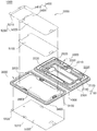
- the protective film attaching apparatus 1000 of the sixth embodiment includes a case 2000 to receive a portable electronic apparatus 10a, a cover 3000 to open and close the case 2000, and a film member 5000 which is provided in the cover 3000.
- the case 2000 may be formed of synthetic resin with small thickness, and may have a protrusion part 2100.
- the protrusion part 2100 is protruded frontward with a predetermined height along inner surface of the case 2000.
- a first receiving groove 2200 is depressed rearward from a front surface of the protrusion part 2100.
- the first receiving groove 2200 may have a shape corresponding to the portable electronic apparatus 10a.
- width, length and depth of the first receiving groove 2200 may be configured according to size and shape of the portable electronic apparatus 10a.
- a first flange portion 2300 having a predetermined width is formed along rear edges of protrusion part 2100.
- the protrusion part 2100 includes a first protrusion part 2110 protruded frontward from the first flange portion 2300 and a second protrusion part 2120 protruded frontward from inner portion of the first protrusion 2110.
- the protrusion part 2100 includes the first and second protrusion parts 2110 and 2120 protruded from an inner surface of the inner surface of the case 2000, and the first receiving groove 2200 is depressed from a front surface of the second protrusion part 2120.
- a first gripping groove 2210 is formed at a side of the first receiving groove 2200 through the first and second protrusion parts 2110 and 2120 to outer side of the case 2000. The user may insert his finger into the first gripping groove 2210 to hold the case 2000 when the cover 3000 is opened.
- second gipping grooves 2220 having a predetermined width are formed along upper and lower edges of the first receiving groove 2200, respectively. The user may take the portable electronic apparatus 10a out of the first receiving groove 2200.
- button groove 2230 is formed corresponding to control button at a side surface of the portable electronic apparatus 10a at an opposite side of the first gripping groove 2210.
- a connecting part 4000 having a predetermined width is formed from the first flange portion 2300 of the case 2000, and the cover 3000 is connected to the connecting part 4000.
- the case 2000, the cover 3000 and the connecting part 4000 may be integrally formed.
- the case 2000 and the cover 3000 may be mutually rotated about the connecting portion 4000.
- folding lines (not shown) along a length direction may be formed at both sides of the connecting part 4000 in a width direction.
- the folding line may be a concave groove along the length direction.
- the folding line may be a dot lines which has a plurality of concave grooves spaced apart by the length direction, or a break line.
- the cover 3000 is formed opposite to the case 2000 with respect to the connecting part 4000.
- the cover 3000 may be folded along the folding line of the connecting part 4000, so that the cover 3000 may open and close a front of the case 3000.
- the cover 3000 includes a third protrusion part 3100 on a rear surface which faces the protrusion part 2100 of the case 2000, a second receiving groove 3200 and a through hole 330 formed through a bottom surface of the second receiving groove 3200.
- the third protrusion part 3100 is protruded rearward with a predetermined height.
- the second receiving groove 3200 is depressed frontward from a surface of the third protrusion part 3100.
- a second flange portion 430 may be formed outward along a boundary of the second protrusion part 410 with a predetermined width.
- a second flange portion 3400 is formed along rear edges of the second protrusion part 2120 with a predetermined width.
- the second protrusion part 2120 of the case 2000 is combined with the second receiving groove 3200 of the cover 3000 in interference fit when the case 2000 is combined with the cover 3000.
- the first protrusion part 2110 makes contact with the third protrusion part 3100 of the cover 3000.
- the film member 5000 is received in the second receiving groove 3200 to face the portable electronic apparatus 10a.
- the film member 5000 includes a protective film 5100 to be attached on a front display area of the portable electronic apparatus 10a, a first release paper 5100 which is attached on a rear surface of the protective film 5100 to protect the protective film 5100, and a second release paper 5300 which is attached on a front surface of the protective film 5100 to protect the protective film 5100.
- boundary of the second release paper 5300 is attached along boundary of the through hole 3300 by an adhesive.
- the protective film 5100 is attached on a bottom surface of the second release paper 5300.
- the protective film 5100 is received in the through hole 3300.
- a first release paper 5200 is attached on a rear surface of the protective film 5100.
- boundary of the second release paper 5300 is attached along edges of the second release paper 5300, so that the protective film 5100 which is attached on the second release paper 5300 is placed in the through hole 3300 with the first release paper 5200.
- an adhesive layer may be formed on the rear surface of the protective film 5100 to firmly attach the protective film 5100 on the front display area of the portable electronic apparatus 10a.
- the protective film 5100 may be formed of synthetic resin such as polyurethane resin or tempered glass.
- first grip tape 5400 and a second grip tape 5500 for easy removing from the protective film 5100 are attached on at a side of the first release paper 5200 and at a side of the second release paper 5300, respectively.
- Each of the first and second grip tapes 5400 and 5500 may be integrally formed with the first and second release paper 5200 and 5300, respectively.
- the first release paper 5200 may include a first-first release paper 5210 attached on upper portion of the protective film 5100 and a first-second release paper 5220 attached on the other portion of the protective film 5100. This may prevent unwanted removing of the protective film 5100 from the second release paper 5300 or movement of the protective film 5100 when the first release paper 5200 is removed.
- first release paper 5200 has too large size, it is possible that the protective film 5100 is removed with the first release paper 5200 when the first release paper 5200 is removed.
- the first release paper 5200 may be divided the first-first release paper 5210 corresponding to a portion where the speaker hole or lens hole is formed and the first-second release paper 5220 corresponding to the other portion.
- the first grip tape 5400 may also include a first-first grip tape 5410 attached on the first-first release paper 5210, and a first-second grip tape 5420 attached on the first-second release paper 5220 .
- the second release paper 5300 has at least one or more of locking hole 5310 is formed along boundary thereof. At least one or more of locking protrusion 3500 is formed on a front surface of the cover 3000 corresponding to the locking hole 5310.
- the locking hole 5310 of the second release paper 5300 guide the film member 5000 to a proper position.
- new film member 500 having the protective film 5100 and the first and second release papers 5200 and 5300 are attached on the cover 3000, so that the case 2000 and cover 3000 may be reusable.
- the locking protrusion 3500 of the cover 3000 is inserted into the locking hole 5310 of the second release paper 5300 when the film member 5000 is attached, so that the protective film 5100 may be placed on a proper position to be attached on the portable electronic apparatus 10a.
- the protective film attaching apparatus 1000 is provided with the film member 5000 in the second receiving groove 3200 and the case 2000 which is combined with the cover 3000.
- the case 2000 may be opened if necessary.
- additional film member 5000 may be separately purchased or separately provided, and then the film member 5000 may be attached on the cover 3000, so that the cover 3000 and the case 2000 may be reusable.
- the cover 3000 is disunited from the case 2000, the portable electronic apparatus 10a is received in the first receiving groove 2200 of the case 2000 configured to expose the front surface of the portable electronic apparatus 10a.
- the first-first release paper 5210 is removed from the film member 5000 received in the second receiving groove 3200. And then, referring to FIG. 34 , by removing the first-second release paper 5220, a rear surface of the protective film 5100 is exposed. Here, order of removing the first-first release paper 5210 and the first-second release paper 5220 may be changed, and an adhesive layer may be formed on the rear surface of the protective film 5100.
- a cover 3000 is closed with the second protrusion part 2120 of the case 2000 is inserted into the second receiving groove 3200 of the cover 3000.
- the front surface of the portable electronic apparatus 10a is received in the second receiving groove 3200, using a pad 6000 which is separately provided or user's finger or palm, the front surface of the second release paper 5300 is rubbed to attach the protective film 5100 on the front display area of the portable electronic apparatus 10a.
- the second release paper 5300 is removed from the cover 3000.
- the protective film 5100 is remained on the front display area of the portable electronic apparatus 10a.
- new film member 5000 is attached on the cover 3000 and the above process may be repeated.
- the locking protrusion 3500 of the cover 3000 is inserted into the locking hole 5310 of the second release paper 5300, so that the film member 5000 may be located in a proper position.
- the film member 5000 which is separately provided or purchased may preferably have a third release paper (not shown) attached along edge of the rear surface of the second release paper 5300.
- the second release paper 5300 is attached along the edge of the through hole 3300 of the cover 3000 with the locking protrusion 3500 being inserted into the locking hole 5310 after the third release paper is removed.
- the protective film is received in the second receiving groove or the through hole, and the portable electronic apparatus is received in the first receiving groove, so that miss-alignment of the protective film due to movement may be prevented, and the protective film may be quickly attached on a correct position with our bubbles.
- the protective film attaching apparatus of the present invention rather than general public is also a trained technician can easily attach the protective film on the front display area of the portable electronic apparatus.
- the protective film may be attached on a correct position with our bubbles, so that cost and time may be saved due to repurchase and rework when the attachment is failed.
Landscapes
- Engineering & Computer Science (AREA)
- Physics & Mathematics (AREA)
- Theoretical Computer Science (AREA)
- General Physics & Mathematics (AREA)
- Nonlinear Science (AREA)
- Manufacturing & Machinery (AREA)
- Human Computer Interaction (AREA)
- General Engineering & Computer Science (AREA)
- Computer Hardware Design (AREA)
- Signal Processing (AREA)
- Computer Networks & Wireless Communication (AREA)
- Optics & Photonics (AREA)
- Chemical & Material Sciences (AREA)
- Textile Engineering (AREA)
- Organic Chemistry (AREA)
- Quality & Reliability (AREA)
- Telephone Set Structure (AREA)
- Crystallography & Structural Chemistry (AREA)
Applications Claiming Priority (4)
| Application Number | Priority Date | Filing Date | Title |
|---|---|---|---|
| KR1020160007770A KR101623905B1 (ko) | 2016-01-21 | 2016-01-21 | 보호필름 부착용 기구 및 이를 이용한 보호필름 부착 방법 |
| JP2016136803A JP6159451B1 (ja) | 2016-01-21 | 2016-07-11 | 保護フィルム貼着用器具及びこれを利用した保護フィルムの貼着方法 |
| CN201610753966.1A CN106985487B (zh) | 2016-01-21 | 2016-08-30 | 保护膜附接装置 |
| PCT/KR2016/013446 WO2017126796A1 (fr) | 2016-01-21 | 2016-11-22 | Instrument de fixation de film protecteur |
Publications (2)
| Publication Number | Publication Date |
|---|---|
| EP3406552A1 true EP3406552A1 (fr) | 2018-11-28 |
| EP3406552A4 EP3406552A4 (fr) | 2020-01-15 |
Family
ID=56114139
Family Applications (1)
| Application Number | Title | Priority Date | Filing Date |
|---|---|---|---|
| EP16886639.0A Withdrawn EP3406552A4 (fr) | 2016-01-21 | 2016-11-22 | Instrument de fixation de film protecteur |
Country Status (5)
| Country | Link |
|---|---|
| US (1) | US20190047815A1 (fr) |
| EP (1) | EP3406552A4 (fr) |
| JP (1) | JP6159451B1 (fr) |
| KR (1) | KR101623905B1 (fr) |
| CN (1) | CN106985487B (fr) |
Cited By (4)
| Publication number | Priority date | Publication date | Assignee | Title |
|---|---|---|---|---|
| CN112968983A (zh) * | 2019-12-13 | 2021-06-15 | Oppo广东移动通信有限公司 | 电子设备及电子设备保护膜的制备方法 |
| KR20230012286A (ko) * | 2021-07-15 | 2023-01-26 | 주식회사 슈피겐코리아 | 보호필름 부착용 가이드장치 |
| US20230416575A1 (en) * | 2021-02-24 | 2023-12-28 | Lg Chem, Ltd. | Method for manufacturing foldable backplate film |
| US20240018397A1 (en) * | 2021-02-24 | 2024-01-18 | Lg Chem, Ltd. | Foldable backplate film manufacturing method |
Families Citing this family (44)
| Publication number | Priority date | Publication date | Assignee | Title |
|---|---|---|---|---|
| KR101623905B1 (ko) * | 2016-01-21 | 2016-05-24 | 주식회사 크레용인터네셔널 | 보호필름 부착용 기구 및 이를 이용한 보호필름 부착 방법 |
| KR101896249B1 (ko) * | 2017-02-27 | 2018-09-10 | (주)루벤틱스 에이디엠 | 휴대형 스마트 기기용 보호 필름 부착 장치 |
| KR101945861B1 (ko) * | 2017-04-11 | 2019-04-29 | (주)화이트스톤 | 스마트 기기의 디스플레이 보호부재 부착장치 및 부착방법 |
| KR102002105B1 (ko) * | 2017-07-14 | 2019-07-22 | (주)화이트스톤 | 스마트 기기의 디스플레이 보호부재 부착장치 및 부착방법 |
| WO2019027846A1 (fr) * | 2017-07-31 | 2019-02-07 | 3M Innovative Properties Company | Film de surfaçage polymère ayant un double contour définissant des formes géométriques à l'intérieur de ce dernier |
| KR102035053B1 (ko) * | 2017-08-04 | 2019-10-22 | (주)화이트스톤 | 스마트 기기의 액정화면 보호부재 부착장치 및 부착방법 |
| US20190149183A1 (en) * | 2017-11-10 | 2019-05-16 | R.R. Donnelley & Sons Company | Apparatus and method for applying a protective cover on an electronic device |
| USD978846S1 (en) | 2018-02-02 | 2023-02-21 | Samsung Display Co., Ltd. | Display module |
| USD978845S1 (en) | 2018-02-02 | 2023-02-21 | Samsung Display Co., Ltd. | Display module |
| USD978847S1 (en) | 2018-02-02 | 2023-02-21 | Samsung Display Co., Ltd. | Display module |
| USD933655S1 (en) * | 2018-02-02 | 2021-10-19 | Samsung Display Co., Ltd. | Display module |
| KR102169780B1 (ko) | 2018-02-28 | 2020-10-26 | 삼성전자주식회사 | 전자장치의 보호필름 부착장치 및 이를 이용한 보호필름 부착방법 |
| JP7105475B2 (ja) * | 2018-05-14 | 2022-07-25 | 株式会社パワーサポート | 治具及び方法 |
| CN108748969B (zh) * | 2018-07-12 | 2024-10-01 | 江门市艾加得电子有限公司 | 便携式贴膜机 |
| US11191334B2 (en) * | 2018-08-21 | 2021-12-07 | MDM Medical LLC | Sterile enclosure for a hand-held electronic device and methods of using thereof |
| KR102609286B1 (ko) * | 2018-09-21 | 2023-12-04 | 삼성디스플레이 주식회사 | 표시 장치의 윈도우 보호 필름 |
| USD1009870S1 (en) | 2018-11-15 | 2024-01-02 | Samsung Display Co., Ltd. | Display panel |
| KR102119337B1 (ko) * | 2019-01-08 | 2020-06-04 | 김재욱 | 스마트폰에 보호필름을 부착시키는 구조 |
| CN109968791B (zh) * | 2019-04-24 | 2023-10-17 | 安道拓(重庆)汽车部件有限公司 | 复合坐垫快速成型装置及成型方法 |
| KR102162940B1 (ko) * | 2019-07-09 | 2020-10-07 | (주)인브로즈 | 액정보호필름 부착방법 및 이에 사용되는 액정보호필름 |
| JP7260909B2 (ja) * | 2019-10-30 | 2023-04-19 | 株式会社オウルテック | 保護フィルム貼付器具 |
| KR102150216B1 (ko) * | 2019-12-19 | 2020-08-31 | 이천우 | 산업용 접착식 패치의 포장대 |
| DE102020106656A1 (de) | 2020-03-11 | 2021-09-16 | E.V.I. Gmbh | Montagevorrichtung |
| CN111392245A (zh) * | 2020-04-27 | 2020-07-10 | 武汉三猪科技有限公司 | 一种方便电子产品屏幕贴膜的包装盒 |
| KR102879865B1 (ko) * | 2020-08-14 | 2025-11-05 | 삼성디스플레이 주식회사 | 이형 필름 |
| KR102599081B1 (ko) * | 2021-07-15 | 2023-11-07 | (주)화이트스톤 | 폴더블 전자 기기의 디스플레이부 프로텍터 부착 장치 및 폴더블 전자 기기의 디스플레이부 프로텍터 부착키트 |
| US11736137B2 (en) * | 2021-08-05 | 2023-08-22 | Shouyun Wang | Mobile phone film attaching device equipped with reinforced glass film |
| GB202113998D0 (en) * | 2021-09-30 | 2021-11-17 | Nicoventures Trading Ltd | A collation of packages |
| JP7569567B2 (ja) * | 2021-11-17 | 2024-10-18 | 東莞市菠蘿光電智造有限公司 | 貼付フィルムおよびフィルム貼付アセンブリ |
| US20230182458A1 (en) * | 2021-12-13 | 2023-06-15 | Shenzhen Momi Electronic Technology Co., LTD. | Film sticking tool and film sticking assembly |
| CN216333046U (zh) * | 2021-12-16 | 2022-04-19 | 深圳市麦格赛伏科技有限公司 | 一种贴膜器、支架及膜组件 |
| CN115033057A (zh) * | 2022-03-29 | 2022-09-09 | 深圳市时代信创新技术有限公司 | 一种个性化的笔记本电脑 |
| WO2024039070A1 (fr) * | 2022-08-16 | 2024-02-22 | 삼성전자주식회사 | Ensemble de montage pour l'assemblage d'un dispositif électronique |
| CN219989612U (zh) * | 2023-06-15 | 2023-11-10 | 深圳酷卡仕科技有限公司 | 手机贴膜辅助装置 |
| CN221212740U (zh) * | 2023-10-09 | 2024-06-25 | 东莞市元谱科技有限公司 | 一种一体式无尘反向贴膜盒 |
| JP3246989U (ja) * | 2023-10-20 | 2024-06-07 | 東莞品佳科技有限公司 | 電子機器用フィルム貼り付けボックス |
| CA228874S (en) * | 2023-12-19 | 2025-01-08 | Electronic Silk Road Shenzhen Tech Co Ltd | Film applicator for mobile phone |
| USD1097742S1 (en) * | 2024-01-22 | 2025-10-14 | Shenzhen Kukashi Technology Co., Ltd | Screen protector installation tool assembly |
| USD1093107S1 (en) * | 2024-01-24 | 2025-09-16 | Shenzhen Kangchengtai Industrial Co., Ltd. | Film applicator |
| KR102785517B1 (ko) * | 2024-06-18 | 2025-03-25 | (주) 스킨메이트 | 보호부재 부착 지그 |
| USD1115475S1 (en) * | 2024-11-28 | 2026-03-03 | Shenzhen Beizun Technology Co., Ltd. | Film applicator |
| USD1127553S1 (en) * | 2025-01-09 | 2026-05-26 | Dongguan Disheng Technology Co., Ltd. | Mobile phone film applicator |
| US12466172B1 (en) * | 2025-03-14 | 2025-11-11 | Hongling Zhu | Film sticking device |
| USD1139260S1 (en) * | 2025-08-20 | 2026-08-04 | Foshan Litu Technology Co., Ltd. | Installation device for a mobile phone screen protector |
Family Cites Families (17)
| Publication number | Priority date | Publication date | Assignee | Title |
|---|---|---|---|---|
| EP0950009B1 (fr) * | 1996-12-31 | 2001-04-11 | Dynosys AG | Dispositif et procede pour appliquer une etiquette autoadhesive sur un article en forme de disque |
| KR200462252Y1 (ko) * | 2011-03-03 | 2012-09-04 | 노종현 | 보호필름 접합구 |
| KR101103436B1 (ko) * | 2011-10-21 | 2012-01-10 | 박재영 | 디스플레이창 보호필름 부착도구 |
| KR200462082Y1 (ko) * | 2012-01-31 | 2012-08-27 | 정흥순 | 모바일 단말기용 정위치 부착 화면 보호 필름 |
| KR200469016Y1 (ko) * | 2012-03-08 | 2013-09-11 | (주) 에이와케이 | 표면보호필름 부착가이드 |
| WO2014049813A1 (fr) * | 2012-09-28 | 2014-04-03 | 任天堂株式会社 | Stratifié de feuille de protection et procédé d'application de feuille de protection |
| JP3180690U (ja) * | 2012-10-19 | 2012-12-27 | スーペリア コミュニケーションズ インク | モバイル装置用保護フィルム貼付装置 |
| TWM449696U (zh) * | 2012-11-13 | 2013-04-01 | Zhan-Rong Xu | 螢幕保護貼之diy貼合裝置 |
| JP3182202U (ja) * | 2012-12-25 | 2013-03-14 | 許瑞峯 | フィルムの貼り付け装置 |
| JP6090915B2 (ja) * | 2013-02-28 | 2017-03-08 | フジコピアン株式会社 | 保護フィルムの貼り付け補助具 |
| KR101441640B1 (ko) * | 2014-02-06 | 2014-09-22 | 심주섭 | 모바일기기용 보호필름 부착장치 |
| CN203854878U (zh) * | 2014-03-18 | 2014-10-01 | 梁肇飞 | 平板电子设备贴膜装置及平板电子设备的保护贴膜 |
| JP2016004092A (ja) * | 2014-06-16 | 2016-01-12 | ユーテック株式会社 | 保護フィルム貼付装置 |
| JP3193806U (ja) * | 2014-08-01 | 2014-10-23 | 株式会社F.K.Solutions | 携帯端末の液晶面への保護材貼着具 |
| KR200478168Y1 (ko) * | 2015-01-14 | 2015-09-03 | 서경림 | 모바일 단말기의 보호부재 부착케이스 |
| JP5845370B1 (ja) * | 2015-06-18 | 2016-01-20 | パナック株式会社 | 保護フィルム貼付用治具 |
| KR101623905B1 (ko) * | 2016-01-21 | 2016-05-24 | 주식회사 크레용인터네셔널 | 보호필름 부착용 기구 및 이를 이용한 보호필름 부착 방법 |
-
2016
- 2016-01-21 KR KR1020160007770A patent/KR101623905B1/ko not_active Expired - Fee Related
- 2016-07-11 JP JP2016136803A patent/JP6159451B1/ja not_active Expired - Fee Related
- 2016-08-30 CN CN201610753966.1A patent/CN106985487B/zh not_active Expired - Fee Related
- 2016-11-22 US US16/070,361 patent/US20190047815A1/en not_active Abandoned
- 2016-11-22 EP EP16886639.0A patent/EP3406552A4/fr not_active Withdrawn
Cited By (6)
| Publication number | Priority date | Publication date | Assignee | Title |
|---|---|---|---|---|
| CN112968983A (zh) * | 2019-12-13 | 2021-06-15 | Oppo广东移动通信有限公司 | 电子设备及电子设备保护膜的制备方法 |
| US20230416575A1 (en) * | 2021-02-24 | 2023-12-28 | Lg Chem, Ltd. | Method for manufacturing foldable backplate film |
| US20240018397A1 (en) * | 2021-02-24 | 2024-01-18 | Lg Chem, Ltd. | Foldable backplate film manufacturing method |
| US12275878B2 (en) * | 2021-02-24 | 2025-04-15 | Lg Chem, Ltd. | Foldable backplate film manufacturing method |
| US12384944B2 (en) * | 2021-02-24 | 2025-08-12 | Lg Chem, Ltd. | Method for manufacturing foldable backplate film |
| KR20230012286A (ko) * | 2021-07-15 | 2023-01-26 | 주식회사 슈피겐코리아 | 보호필름 부착용 가이드장치 |
Also Published As
| Publication number | Publication date |
|---|---|
| CN106985487A (zh) | 2017-07-28 |
| EP3406552A4 (fr) | 2020-01-15 |
| KR101623905B1 (ko) | 2016-05-24 |
| JP6159451B1 (ja) | 2017-07-05 |
| CN106985487B (zh) | 2019-12-10 |
| US20190047815A1 (en) | 2019-02-14 |
| JP2017130907A (ja) | 2017-07-27 |
Similar Documents
| Publication | Publication Date | Title |
|---|---|---|
| US20190047815A1 (en) | Protective film attaching apparatus | |
| US11772321B1 (en) | Applicator for applying protective coverings to electronic device displays | |
| KR200475419Y1 (ko) | 모바일 단말기의 액정보호부재 부착케이스 | |
| KR200475420Y1 (ko) | 모바일 단말기의 슬라이딩타입 액정보호부재 부착케이스s | |
| US20200064883A1 (en) | Device and method for applying protective films | |
| EP2891552B1 (fr) | Applicateur | |
| KR101252750B1 (ko) | 휴대전자기기 디스플레이부 보호필름 부착장치, 휴대전자기기 디스플레이부 보호필름 부착용 시트, 및 휴대전자기기 디스플레이부 보호필름 부착방법 | |
| JP6090915B2 (ja) | 保護フィルムの貼り付け補助具 | |
| US20070021068A1 (en) | User applied template cover for hand-held music player | |
| KR200464476Y1 (ko) | 휴대전자기기 디스플레이부 보호필름 부착장치 및 키트 | |
| KR20160022665A (ko) | 모바일 단말기의 슬라이딩타입 액정보호부재 부착케이스 | |
| EP2730992A2 (fr) | Dispositif et procédé permettant d'installer un écran protecteur | |
| EP3677427A1 (fr) | Applicateur de recouvrement | |
| KR200469016Y1 (ko) | 표면보호필름 부착가이드 | |
| KR20160098692A (ko) | 스마트폰 액정보호필름 가이드지그 | |
| KR20070108895A (ko) | 필터 매체 리테이너 | |
| EP3046262A1 (fr) | Boîtier de fixation protecteur pour terminal mobile | |
| US20190149183A1 (en) | Apparatus and method for applying a protective cover on an electronic device | |
| JP6279534B2 (ja) | フラットパネルディスプレイ装置用保護カバーの貼付治具およびフラットパネルディスプレイ装置用保護カバーの貼り付けキット | |
| KR20180126194A (ko) | 이물질 제거 필름이 일체로 형성된 휴대용 전자기기의 액정보호필름 | |
| JP3207363U (ja) | 携帯端末の液晶保護フィルム付着ケース | |
| KR102376283B1 (ko) | 이동단말기의 액정 보호필름 어셈블리 | |
| KR20140002324A (ko) | 휴대폰 보호필름 구조체 | |
| KR102142274B1 (ko) | 주문처리용 랙 어셈블리 | |
| JP5150304B2 (ja) | 標示具 |
Legal Events
| Date | Code | Title | Description |
|---|---|---|---|
| STAA | Information on the status of an ep patent application or granted ep patent |
Free format text: STATUS: THE INTERNATIONAL PUBLICATION HAS BEEN MADE |
|
| PUAI | Public reference made under article 153(3) epc to a published international application that has entered the european phase |
Free format text: ORIGINAL CODE: 0009012 |
|
| STAA | Information on the status of an ep patent application or granted ep patent |
Free format text: STATUS: REQUEST FOR EXAMINATION WAS MADE |
|
| 17P | Request for examination filed |
Effective date: 20180821 |
|
| AK | Designated contracting states |
Kind code of ref document: A1 Designated state(s): AL AT BE BG CH CY CZ DE DK EE ES FI FR GB GR HR HU IE IS IT LI LT LU LV MC MK MT NL NO PL PT RO RS SE SI SK SM TR |
|
| AX | Request for extension of the european patent |
Extension state: BA ME |
|
| DAV | Request for validation of the european patent (deleted) | ||
| DAX | Request for extension of the european patent (deleted) | ||
| RIC1 | Information provided on ipc code assigned before grant |
Ipc: G06F 1/16 20060101AFI20190828BHEP Ipc: H04M 1/02 20060101ALN20190828BHEP Ipc: H04M 1/18 20060101ALN20190828BHEP Ipc: B29C 63/00 20060101ALN20190828BHEP Ipc: B29C 63/02 20060101ALI20190828BHEP Ipc: H04B 1/3888 20150101ALI20190828BHEP Ipc: A45C 11/00 20060101ALN20190828BHEP |
|
| A4 | Supplementary search report drawn up and despatched |
Effective date: 20191212 |
|
| RIC1 | Information provided on ipc code assigned before grant |
Ipc: G06F 1/16 20060101AFI20191206BHEP Ipc: H04M 1/02 20060101ALN20191206BHEP Ipc: B29C 63/00 20060101ALN20191206BHEP Ipc: A45C 11/00 20060101ALN20191206BHEP Ipc: H04M 1/18 20060101ALN20191206BHEP Ipc: B29C 63/02 20060101ALI20191206BHEP Ipc: H04B 1/3888 20150101ALI20191206BHEP |
|
| STAA | Information on the status of an ep patent application or granted ep patent |
Free format text: STATUS: THE APPLICATION IS DEEMED TO BE WITHDRAWN |
|
| 18D | Application deemed to be withdrawn |
Effective date: 20200721 |