EP3406800A1 - Kehrmaschine - Google Patents
Kehrmaschine Download PDFInfo
- Publication number
- EP3406800A1 EP3406800A1 EP18173537.4A EP18173537A EP3406800A1 EP 3406800 A1 EP3406800 A1 EP 3406800A1 EP 18173537 A EP18173537 A EP 18173537A EP 3406800 A1 EP3406800 A1 EP 3406800A1
- Authority
- EP
- European Patent Office
- Prior art keywords
- handle
- shield
- coupled
- drive shaft
- brush
- Prior art date
- Legal status (The legal status is an assumption and is not a legal conclusion. Google has not performed a legal analysis and makes no representation as to the accuracy of the status listed.)
- Granted
Links
Images



Classifications
-
- E—FIXED CONSTRUCTIONS
- E01—CONSTRUCTION OF ROADS, RAILWAYS, OR BRIDGES
- E01H—STREET CLEANING; CLEANING OF PERMANENT WAYS; CLEANING BEACHES; DISPERSING OR PREVENTING FOG IN GENERAL CLEANING STREET OR RAILWAY FURNITURE OR TUNNEL WALLS
- E01H1/00—Removing undesirable matter from roads or like surfaces, with or without moistening of the surface
- E01H1/02—Brushing apparatus, e.g. with auxiliary instruments for mechanically loosening dirt
- E01H1/05—Brushing apparatus, e.g. with auxiliary instruments for mechanically loosening dirt with driven brushes
- E01H1/056—Brushing apparatus, e.g. with auxiliary instruments for mechanically loosening dirt with driven brushes having horizontal axes
-
- A—HUMAN NECESSITIES
- A47—FURNITURE; DOMESTIC ARTICLES OR APPLIANCES; COFFEE MILLS; SPICE MILLS; SUCTION CLEANERS IN GENERAL
- A47L—DOMESTIC WASHING OR CLEANING; SUCTION CLEANERS IN GENERAL
- A47L11/00—Machines for cleaning floors, carpets, furniture, walls, or wall coverings
- A47L11/24—Floor-sweeping machines, motor-driven
-
- A—HUMAN NECESSITIES
- A47—FURNITURE; DOMESTIC ARTICLES OR APPLIANCES; COFFEE MILLS; SPICE MILLS; SUCTION CLEANERS IN GENERAL
- A47L—DOMESTIC WASHING OR CLEANING; SUCTION CLEANERS IN GENERAL
- A47L11/00—Machines for cleaning floors, carpets, furniture, walls, or wall coverings
- A47L11/40—Parts or details of machines not provided for in groups A47L11/02 - A47L11/38, or not restricted to one of these groups, e.g. handles, arrangements of switches, skirts, buffers, levers
- A47L11/4036—Parts or details of the surface treating tools
- A47L11/4041—Roll shaped surface treating tools
-
- A—HUMAN NECESSITIES
- A47—FURNITURE; DOMESTIC ARTICLES OR APPLIANCES; COFFEE MILLS; SPICE MILLS; SUCTION CLEANERS IN GENERAL
- A47L—DOMESTIC WASHING OR CLEANING; SUCTION CLEANERS IN GENERAL
- A47L11/00—Machines for cleaning floors, carpets, furniture, walls, or wall coverings
- A47L11/40—Parts or details of machines not provided for in groups A47L11/02 - A47L11/38, or not restricted to one of these groups, e.g. handles, arrangements of switches, skirts, buffers, levers
- A47L11/4072—Arrangement of castors or wheels
-
- A—HUMAN NECESSITIES
- A47—FURNITURE; DOMESTIC ARTICLES OR APPLIANCES; COFFEE MILLS; SPICE MILLS; SUCTION CLEANERS IN GENERAL
- A47L—DOMESTIC WASHING OR CLEANING; SUCTION CLEANERS IN GENERAL
- A47L11/00—Machines for cleaning floors, carpets, furniture, walls, or wall coverings
- A47L11/40—Parts or details of machines not provided for in groups A47L11/02 - A47L11/38, or not restricted to one of these groups, e.g. handles, arrangements of switches, skirts, buffers, levers
- A47L11/4075—Handles; levers
-
- B—PERFORMING OPERATIONS; TRANSPORTING
- B08—CLEANING
- B08B—CLEANING IN GENERAL; PREVENTION OF FOULING IN GENERAL
- B08B1/00—Cleaning by methods involving the use of tools
- B08B1/10—Cleaning by methods involving the use of tools characterised by the type of cleaning tool
- B08B1/12—Brushes
-
- B—PERFORMING OPERATIONS; TRANSPORTING
- B08—CLEANING
- B08B—CLEANING IN GENERAL; PREVENTION OF FOULING IN GENERAL
- B08B1/00—Cleaning by methods involving the use of tools
- B08B1/30—Cleaning by methods involving the use of tools by movement of cleaning members over a surface
- B08B1/32—Cleaning by methods involving the use of tools by movement of cleaning members over a surface using rotary cleaning members
- B08B1/34—Cleaning by methods involving the use of tools by movement of cleaning members over a surface using rotary cleaning members rotating about an axis parallel to the surface
-
- E—FIXED CONSTRUCTIONS
- E01—CONSTRUCTION OF ROADS, RAILWAYS, OR BRIDGES
- E01H—STREET CLEANING; CLEANING OF PERMANENT WAYS; CLEANING BEACHES; DISPERSING OR PREVENTING FOG IN GENERAL CLEANING STREET OR RAILWAY FURNITURE OR TUNNEL WALLS
- E01H1/00—Removing undesirable matter from roads or like surfaces, with or without moistening of the surface
- E01H1/02—Brushing apparatus, e.g. with auxiliary instruments for mechanically loosening dirt
- E01H1/04—Brushing apparatus, e.g. with auxiliary instruments for mechanically loosening dirt taking- up the sweepings, e.g. for collecting, for loading
- E01H1/042—Brushing apparatus, e.g. with auxiliary instruments for mechanically loosening dirt taking- up the sweepings, e.g. for collecting, for loading the loading means being an endless belt or an auger
-
- E—FIXED CONSTRUCTIONS
- E01—CONSTRUCTION OF ROADS, RAILWAYS, OR BRIDGES
- E01H—STREET CLEANING; CLEANING OF PERMANENT WAYS; CLEANING BEACHES; DISPERSING OR PREVENTING FOG IN GENERAL CLEANING STREET OR RAILWAY FURNITURE OR TUNNEL WALLS
- E01H1/00—Removing undesirable matter from roads or like surfaces, with or without moistening of the surface
- E01H1/02—Brushing apparatus, e.g. with auxiliary instruments for mechanically loosening dirt
- E01H1/04—Brushing apparatus, e.g. with auxiliary instruments for mechanically loosening dirt taking- up the sweepings, e.g. for collecting, for loading
- E01H1/045—Brushing apparatus, e.g. with auxiliary instruments for mechanically loosening dirt taking- up the sweepings, e.g. for collecting, for loading the loading means being a rotating brush with horizontal axis
Definitions
- the present invention relates to power sweepers.
- Power sweepers are typically used for sweeping large hard surfaces such as driveways, parking areas, hard surface sports courts, patios, roadways and the like.
- the sweeper includes a frame with a handle graspable by a used and an axle mounting a pair of wheels to facilitate movement of the sweeped across the swept surface. Adjacent the wheels is a driven brush for performing the sweeping operation.
- the present invention seeks to provide a useful alternative to current power sweepers.
- Some embodiments of the invention include a power sweeper having a handle with a first end graspable by a user and a second end, a drive shaft extending along the handle, and a power head coupled to the handle to rotate the drive shaft.
- a gear box is coupled to the drive shaft adjacent the second end and a brush is coupled to the gear box for rotation in response to rotation of the drive shaft.
- the power sweeper includes an axle, a first wheel coupled to the axle, the first wheel being configured to roll along a ground surface, and a second wheel coupled to the axle, the second wheel being configured to roll along the ground surface.
- a shield is coupled to the gear box and defines an aperture through which the handle extends. The axle is moveable with respect to the shield and the brush to adjust an angle between the handle and the ground surface.
- the brush may define a circumference and wherein the shield may extend around a portion of the circumference of the brush.
- the drive shaft may extend along substantially an entire length of the handle between the handle first end and the handle second end.
- the power sweeper may further comprise a cap coupled to the second end of the handle, the cap being removable from the second end of the handle to uncover the drive shaft, and wherein the power head may be removably coupled to the second end of the handle
- the power sweeper may further comprise a bracket coupled to the axle, wherein the shield may define a first aperture and the bracket may define a second aperture, and the power sweeper may further comprise a fastener extending through the first aperture and the second aperture to couple the bracket to the shield.
- the second aperture may be an elongate slot such that the shield can be coupled to the bracket at a plurality of locations to permit adjustment of the angle between the handle and the ground surface.
- Some embodiments of the invention include a method of adjusting an angle of a handle of a power sweeper with respect to a support surface.
- the method includes coupling a pair of wheels to an axle, coupling a support member to the axle, coupling a handle to the support member, extending a drive shaft through the handle, coupling a power head to a first end of the drive shaft, coupling a brush to a second end of the drive shaft, rotating the brush with the drive shaft in response operation of the power head, and moving the support member with respect to the axle to change an angle between the handle and the support surface.
- Rotating the brush may include cleaning the support surface.
- the method may further comprise coupling a shield to the support member by inserting a fastener through a first aperture in the shield and through a second aperture in the support member.
- the method may further comprise loosening the fastener prior to moving the shield with respect to the support member, and tightening the fastener after moving the shield with respect to the support member.
- the method may further comprise coupling a gearbox to the axle and coupling the brush to the gearbox, such that the drive shaft rotates the brush via the gearbox.
- the method may further comprise coupling a shield to the gearbox such that the shield extends around a portion of the brush.
- the method may further comprise fixing the support member to the axle, and coupling a shield to the support member, wherein moving the shield with respect to the axle includes moving the shield with respect to the support member.
- Some embodiments of the invention include a power sweeper configured to be coupled to a power head.
- the power sweeper includes a handle graspable by a user, a wheel coupled to the handle, and a brush coupled to at least one of the handle and the wheel.
- a drive shaft is coupled to the brush to rotate the brush.
- the drive shaft is configured to be rotated by the power head.
- a shield is coupled to the wheel and defines an aperture through which the handle extends. The shield is moveable with respect to the wheel to adjust an angle between the handle and a ground surface.
- the power sweeper may further comprise a gear box coupled to the drive shaft and the brush, wherein the shield is coupled to the gear box and the shield extends around a portion of a circumference of the brush.
- a first end of the handle may be coupled to the wheel and a second end of the handle may be spaced from the wheel, wherein the drive shaft extends along substantially an entire length of the handle between the handle first end and the handle second end.
- the power sweeper may further comprise a cap coupled to the second end of the handle, the cap being removable from the second end of the handle to uncover the drive shaft, and wherein the power head is removably coupled to the second end of the handle,.
- the wheel may be a first wheel and the power sweeper may further comprise a second wheel and an axle extending between the first wheel and the second wheel, and further comprise a bracket coupled to the axle and coupled to the shield,.
- the shield may define a first aperture and the bracket may define a second aperture, and the power sweeper may further comprise a fastener extending through the first aperture and the second aperture to couple the bracket to the shield,.
- the second aperture may be an elongate slot such that the shield can be coupled to the bracket at a plurality of locations to permit adjustment of the angle between the handle and the support surface.
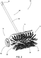
- Fig. 1 illustrates a power sweeper 10.
- the power sweeper 10 includes a sweeping assembly 12, a shield 14, a handle assembly 16, and a wheel assembly 18.
- the illustrated sweeping assembly 12 includes a gearbox 20, and a driven shaft 22, and a brush 24.
- the driven shaft 22 is coupled to the gearbox 20 such that the gearbox 20 rotates the driven shaft 22.
- the gearbox 20 includes a tiller gearbox.
- the brush 24 is coupled to the driven shaft 22 for rotation with the driven shaft 22 by the gearbox 20.
- the brush 24 includes nylon bristles.
- other suitable types of brushes which may or may not include bristles, can be utilized.
- the brush could include a plurality of rubber blades.
- the shield 14 is coupled to the gearbox 20 such that the shield is fixed from movement relative to the gearbox 20.
- the shield 14 includes an aperture 26.
- the gearbox 20 extends into the aperture 26 to facilitate properly aligning and locating the position of the gearbox 20 relative to the shield 14 during assembly of the sweeper 10.
- the illustrated shield 14 is generally arcuate and the shield curves around a portion of the brush 24.
- the shield 14 is made from polypropylene. The shield 14 inhibits debris pushed by the brush 24 from going back toward the user.
- the handle assembly 16 includes a handle 30, a drive shaft 32 inside the handle, and a cap 34.
- the handle 30 is hollow and includes a first end 36 and a second end 38.
- the first end 36 ( Fig. 5 ) of the handle 30 is adjacent the gearbox 20.
- the handle 30 is generally fixed to the gearbox 20.
- the second end 38 of the handle 30 includes the cap 34.
- the cap 34 is removable to access the drive shaft 32.
- the drive shaft 32 includes a first end that is received in the gearbox 20 and a second end 40 ( Fig. 3 ) adjacent the second end 38 of the handle 30.
- the second end 40 of the drive shaft 32 is accessible when the cap 34 is removed.
- the second end 38 of the handle 30 and the second end 40 of the drive shaft 32 can be connected to a power head 44 to rotate the drive shaft 32 relative to the handle 30.
- the power head 44 can include a two-cycle gas engine, a battery powered electric motor, or an A-C electric motor.
- the illustrated power head 44 is coupled to the second end 38 of the handle 30 via an elongate shaft 48.
- a gripping portion 52 is also coupled to the elongate shaft 48 in the illustrated embodiment. In the illustrated embodiment, the gripping portion 52 is removably coupled to the elongate shaft 48 such that other sizes and shapes of gripping portions can be utilized in place of the illustrated gripping portion 52.
- the power head 44 is part of kit that includes additional tools for use with the power head such as a string trimmer, edger, blower, shrub trimmer and the like.
- Rotation of the drive shaft 32 by the power head 44 rotates the driven shaft 22 of the sweeping assembly 12 via the gearbox 20.
- the handle 30 and the drive shaft 32 are straight but in other embodiments the handle and drive shaft can be curved.
- the wheel assembly 18 includes a bracket 58, an axle 60, and wheels 62.
- the axle 60 extends through the bracket 58 and couples the wheels 62 to the bracket 58.
- each wheel 62 is removably coupled to the axle 60 using a washer and a cotter pin.
- the bracket 58 includes a flange 68 and elongated recesses 70 ( Fig. 5 ) that extend through the flange 68.
- Each recess 70 has a first end 72 and a second end 74.
- the bracket 58 and wheel assembly 18 are coupled to the shield 14 and sweeping assembly 12 using fasteners 76 that extend through the recesses 70. Referring to Fig.
- the illustrated fasteners 76 include a nut 78 and a bolt 80.
- other types of fasters can be used, such as a bolt and wing nut, quick release type fasteners, knobs and bolts, and the like.
- the user uses the power head 44 to rotate the drive shaft 32.
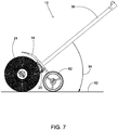
- Rotation of the drive shaft 32 rotates the brush 24 and the sweeper 10 is used for sweeping a surface 82 ( Fig. 7 ), such as a driveway, sidewalk, lawn, and the like.
- the wheels 62 and handle 30 facilitate easy movement of the sweeper 10 along the surface 82 being swept.
- the wheels 62 and axle 60 provide a pivot point about which the user can rotate the brush 24 using the handle 30.
- the user can push down on the handle 30, which raises the brush 24 from the surface 82.
- the user can lift the handle 30, which increases the pressure applied by the brush 24 on the surface 82.
- the user can also adjust the angle 84 between the handle 30 and the surface 82 using the fasteners 76.
- the fasteners 76 By loosening the fasteners 76 (see Fig. 5 ) the user can slide the flange 68 relative to the shield 14 in the direction of arrow A to adjust the angle 84 and then re-tighten the fasteners 76. If the bolts 80 are positioned at the first ends 72 of the recesses 70, the angle 84 is maximized. If the bolts 80 are positioned at the second ends 74 of the recesses 70, the angle 84 is minimized.
- the angle 84 can be adjusted anywhere in a range from 35 degrees to 40 degrees. In another embodiment, the angle 84 can be adjusted anywhere in a range from 30 degrees to 45 degrees. Adjustment of the angle 84 allows the user to position the handle 30 for maximum conform and performance based on conditions such as the user's height and surface being swept.
Landscapes
- Engineering & Computer Science (AREA)
- Architecture (AREA)
- Civil Engineering (AREA)
- Structural Engineering (AREA)
- Harvester Elements (AREA)
- Cleaning In General (AREA)
Applications Claiming Priority (1)
| Application Number | Priority Date | Filing Date | Title |
|---|---|---|---|
| US201762509274P | 2017-05-22 | 2017-05-22 |
Publications (2)
| Publication Number | Publication Date |
|---|---|
| EP3406800A1 true EP3406800A1 (de) | 2018-11-28 |
| EP3406800B1 EP3406800B1 (de) | 2020-02-12 |
Family
ID=62222490
Family Applications (1)
| Application Number | Title | Priority Date | Filing Date |
|---|---|---|---|
| EP18173537.4A Active EP3406800B1 (de) | 2017-05-22 | 2018-05-22 | Kehrmaschine |
Country Status (6)
| Country | Link |
|---|---|
| US (1) | US11148176B2 (de) |
| EP (1) | EP3406800B1 (de) |
| CN (1) | CN108951488A (de) |
| AU (1) | AU2018203553B2 (de) |
| CA (1) | CA3005336A1 (de) |
| MX (1) | MX2018006322A (de) |
Cited By (1)
| Publication number | Priority date | Publication date | Assignee | Title |
|---|---|---|---|---|
| CN111350149A (zh) * | 2020-04-16 | 2020-06-30 | 曾多 | 一种建筑工程工地使用的清理设备 |
Families Citing this family (10)
| Publication number | Priority date | Publication date | Assignee | Title |
|---|---|---|---|---|
| US11917951B2 (en) * | 2019-05-22 | 2024-03-05 | Nanjing Chervon Industry Co., Ltd. | Sweeper head and hand-held sweeper |
| CN111227721B (zh) * | 2020-02-28 | 2021-09-21 | 台州德善科技有限公司 | 一种木材加工余料木屑自动化收集处理装置 |
| CA3152680C (en) | 2021-03-17 | 2025-02-11 | Dupray Ventures Inc. | STAIN REMOVAL DEVICE |
| WO2022225853A1 (en) | 2021-04-19 | 2022-10-27 | Milwaukee Electric Tool Corporation | String trimmer head |
| WO2023278734A1 (en) | 2021-06-30 | 2023-01-05 | Milwaukee Electric Tool Corporation | String trimmer head |
| DE212022000197U1 (de) | 2021-06-30 | 2024-02-19 | Milwaukee Electric Tool Corporation | Fadentrimmeranordung und Trimmerkopf zur Verwendung damit |
| USD1017156S1 (en) | 2022-05-09 | 2024-03-05 | Dupray Ventures Inc. | Cleaner |
| USD1105672S1 (en) | 2023-08-30 | 2025-12-09 | Sharkninja Operating Llc | Vacuum cleaner and vacuum nozzle |
| USD1073222S1 (en) * | 2023-11-13 | 2025-04-29 | YYBS Company Ltd. | Push sweeper |
| USD1113019S1 (en) | 2024-05-31 | 2026-02-10 | Sharkninja Operating Llc | Steam cleaner |
Citations (3)
| Publication number | Priority date | Publication date | Assignee | Title |
|---|---|---|---|---|
| US2205249A (en) * | 1938-08-17 | 1940-06-18 | Fitzgerald William Ralph | Cleaning machine |
| US2933748A (en) * | 1957-09-11 | 1960-04-26 | Parker Sweeper Company | Power operated tool |
| US20130212815A1 (en) * | 2012-02-22 | 2013-08-22 | Russell J. Kempf | Gauge wheel assembly for hand held portable power tool |
Family Cites Families (17)
| Publication number | Priority date | Publication date | Assignee | Title |
|---|---|---|---|---|
| US4286675A (en) * | 1979-06-25 | 1981-09-01 | Beaird-Poulan Division Of Emerson Electric Co. | Narrow profile power handle for line trimmer and the like |
| SE439792B (sv) * | 1984-03-16 | 1985-07-01 | Gosta Agergard | Sopmaskin |
| NL1022079C1 (nl) | 2002-12-04 | 2004-06-07 | Kinzo B V | Toestel voor het verwijderen van onkruid uit voegen van bestrating. |
| DE4223764B4 (de) | 1992-07-18 | 2004-06-03 | Fa. Andreas Stihl | Handgeführter Kantenschneider |
| WO1999007202A1 (de) | 1997-08-06 | 1999-02-18 | Andreas Stihl Ag & Co. | Handgeführter, tragbarer balkenmäher |
| US6688404B2 (en) | 1999-03-27 | 2004-02-10 | Andreas Stihl Ag & Co. | Portable handheld edge cutter |
| DE10248642A1 (de) | 2002-10-18 | 2004-04-29 | Andreas Stihl Ag & Co. Kg | Handgeführtes Arbeitsgerät |
| DE20304278U1 (de) | 2003-03-18 | 2003-05-28 | Andreas Stihl AG & Co. KG, 71336 Waiblingen | Führungswagen |
| US7373685B2 (en) | 2003-08-20 | 2008-05-20 | Peter Ho Ka Nam | Mechanical sweeper configuration |
| DE102004042708A1 (de) | 2004-09-03 | 2006-03-09 | Andreas Stihl Ag & Co. Kg | Handgeführte Kehrwalze |
| US7891036B2 (en) | 2005-03-18 | 2011-02-22 | Techtronic Outdoor Products Technology Limited | Multi-function power washer |
| DE102007045618A1 (de) | 2007-09-17 | 2009-03-19 | Alfred Kärcher Gmbh & Co. Kg | Bodenreinigungsgerät |
| US8677543B2 (en) | 2007-10-23 | 2014-03-25 | Larry C. Wilkins | Fluid-powered cleaning device |
| WO2010079126A1 (de) | 2009-01-09 | 2010-07-15 | Andreas Stihl Ag & Co.Kg | Vorrichtung zur reinigung gepflasterter flächen |
| US9027189B2 (en) | 2012-12-19 | 2015-05-12 | Agri-Fab, Inc. | Brush height setting assembly and method |
| US9636817B2 (en) * | 2013-08-02 | 2017-05-02 | D.J.S. Enterprises, Inc. | Outdoor multi-use hand tool |
| MA39277A (fr) | 2014-04-17 | 2017-06-27 | Ip Cleaning S P A | Machine de nettoyage de surfaces |
-
2018
- 2018-05-18 CA CA3005336A patent/CA3005336A1/en active Pending
- 2018-05-21 US US15/984,463 patent/US11148176B2/en active Active
- 2018-05-21 AU AU2018203553A patent/AU2018203553B2/en active Active
- 2018-05-21 CN CN201810490825.4A patent/CN108951488A/zh active Pending
- 2018-05-22 MX MX2018006322A patent/MX2018006322A/es unknown
- 2018-05-22 EP EP18173537.4A patent/EP3406800B1/de active Active
Patent Citations (3)
| Publication number | Priority date | Publication date | Assignee | Title |
|---|---|---|---|---|
| US2205249A (en) * | 1938-08-17 | 1940-06-18 | Fitzgerald William Ralph | Cleaning machine |
| US2933748A (en) * | 1957-09-11 | 1960-04-26 | Parker Sweeper Company | Power operated tool |
| US20130212815A1 (en) * | 2012-02-22 | 2013-08-22 | Russell J. Kempf | Gauge wheel assembly for hand held portable power tool |
Cited By (2)
| Publication number | Priority date | Publication date | Assignee | Title |
|---|---|---|---|---|
| CN111350149A (zh) * | 2020-04-16 | 2020-06-30 | 曾多 | 一种建筑工程工地使用的清理设备 |
| CN111350149B (zh) * | 2020-04-16 | 2021-11-09 | 上安实业江苏有限公司 | 一种建筑工程工地使用的清理设备 |
Also Published As
| Publication number | Publication date |
|---|---|
| EP3406800B1 (de) | 2020-02-12 |
| CN108951488A (zh) | 2018-12-07 |
| US11148176B2 (en) | 2021-10-19 |
| AU2018203553A1 (en) | 2018-12-06 |
| AU2018203553B2 (en) | 2019-04-18 |
| US20180333753A1 (en) | 2018-11-22 |
| CA3005336A1 (en) | 2018-11-22 |
| MX2018006322A (es) | 2019-03-28 |
Similar Documents
| Publication | Publication Date | Title |
|---|---|---|
| EP3406800B1 (de) | Kehrmaschine | |
| US2863162A (en) | Snow sweeping attachment for lawn mower | |
| US20130212815A1 (en) | Gauge wheel assembly for hand held portable power tool | |
| CA2057704C (en) | Power sweeping tool | |
| US20060096135A1 (en) | Adjustable handle for portable tool | |
| CA2113260C (en) | Hand held powered rotary sweeper with belt mounted blades | |
| US6802098B2 (en) | Cylindrical brush idler-side taper adjustment assembly | |
| US9636817B2 (en) | Outdoor multi-use hand tool | |
| US20070289283A1 (en) | Raking devices for pull-type and push-type applications and adapters and methods for retrofitting pull-type raking devices for pull- and push-type applications | |
| US20170056938A1 (en) | Device for clearing an area around elevated objects | |
| EP4520152A2 (de) | Ziehbare elemente für rasenmäher und rasenmäher mit ziehbaren elementen | |
| CN207435988U (zh) | 一种基于装载机平台的扫雪装置 | |
| KR20150004345U (ko) | 관리기를 이용한 제설장치 | |
| JP6060446B2 (ja) | 人工芝生清掃車 | |
| CN2845698Y (zh) | 滚动清扫器 | |
| KR101318016B1 (ko) | 조립식 다중 작업기 | |
| RU214662U1 (ru) | Механическая метла | |
| RU2709699C1 (ru) | Ручная электрическая аккумуляторная метла для уборки снега, льда, воды, земли, листьев и мусора | |
| CN205636619U (zh) | 自行式抛雪清扫一体机 | |
| RU19058U1 (ru) | Ручная машина для подметания территории | |
| CN222100709U (zh) | 一种适合大宽度车道清扫的清扫车 | |
| CN220266254U (zh) | 高速公路多功能路面打磨一体机 | |
| DE202011105973U1 (de) | Motorgetriebene Leichtkehrmaschine zum Kehren von Schmutz, Staub, Wasser oder Schnee | |
| CN109281283A (zh) | 一种带有清扫功能的锋利型推雪铲 | |
| DK9400316U3 (da) | Sidemonteret, roterende fejekost |
Legal Events
| Date | Code | Title | Description |
|---|---|---|---|
| PUAI | Public reference made under article 153(3) epc to a published international application that has entered the european phase |
Free format text: ORIGINAL CODE: 0009012 |
|
| STAA | Information on the status of an ep patent application or granted ep patent |
Free format text: STATUS: THE APPLICATION HAS BEEN PUBLISHED |
|
| AK | Designated contracting states |
Kind code of ref document: A1 Designated state(s): AL AT BE BG CH CY CZ DE DK EE ES FI FR GB GR HR HU IE IS IT LI LT LU LV MC MK MT NL NO PL PT RO RS SE SI SK SM TR |
|
| AX | Request for extension of the european patent |
Extension state: BA ME |
|
| STAA | Information on the status of an ep patent application or granted ep patent |
Free format text: STATUS: REQUEST FOR EXAMINATION WAS MADE |
|
| 17P | Request for examination filed |
Effective date: 20190401 |
|
| RBV | Designated contracting states (corrected) |
Designated state(s): AL AT BE BG CH CY CZ DE DK EE ES FI FR GB GR HR HU IE IS IT LI LT LU LV MC MK MT NL NO PL PT RO RS SE SI SK SM TR |
|
| GRAP | Despatch of communication of intention to grant a patent |
Free format text: ORIGINAL CODE: EPIDOSNIGR1 |
|
| STAA | Information on the status of an ep patent application or granted ep patent |
Free format text: STATUS: GRANT OF PATENT IS INTENDED |
|
| INTG | Intention to grant announced |
Effective date: 20190906 |
|
| GRAS | Grant fee paid |
Free format text: ORIGINAL CODE: EPIDOSNIGR3 |
|
| GRAA | (expected) grant |
Free format text: ORIGINAL CODE: 0009210 |
|
| STAA | Information on the status of an ep patent application or granted ep patent |
Free format text: STATUS: THE PATENT HAS BEEN GRANTED |
|
| AK | Designated contracting states |
Kind code of ref document: B1 Designated state(s): AL AT BE BG CH CY CZ DE DK EE ES FI FR GB GR HR HU IE IS IT LI LT LU LV MC MK MT NL NO PL PT RO RS SE SI SK SM TR |
|
| REG | Reference to a national code |
Ref country code: GB Ref legal event code: FG4D |
|
| REG | Reference to a national code |
Ref country code: CH Ref legal event code: EP |
|
| REG | Reference to a national code |
Ref country code: AT Ref legal event code: REF Ref document number: 1232252 Country of ref document: AT Kind code of ref document: T Effective date: 20200215 |
|
| RAP2 | Party data changed (patent owner data changed or rights of a patent transferred) |
Owner name: TTI (MACAO COMMERCIAL OFFSHORE) LIMITED |
|
| REG | Reference to a national code |
Ref country code: IE Ref legal event code: FG4D |
|
| REG | Reference to a national code |
Ref country code: DE Ref legal event code: R096 Ref document number: 602018002357 Country of ref document: DE |
|
| PG25 | Lapsed in a contracting state [announced via postgrant information from national office to epo] |
Ref country code: RS Free format text: LAPSE BECAUSE OF FAILURE TO SUBMIT A TRANSLATION OF THE DESCRIPTION OR TO PAY THE FEE WITHIN THE PRESCRIBED TIME-LIMIT Effective date: 20200212 Ref country code: FI Free format text: LAPSE BECAUSE OF FAILURE TO SUBMIT A TRANSLATION OF THE DESCRIPTION OR TO PAY THE FEE WITHIN THE PRESCRIBED TIME-LIMIT Effective date: 20200212 Ref country code: NO Free format text: LAPSE BECAUSE OF FAILURE TO SUBMIT A TRANSLATION OF THE DESCRIPTION OR TO PAY THE FEE WITHIN THE PRESCRIBED TIME-LIMIT Effective date: 20200512 |
|
| REG | Reference to a national code |
Ref country code: LT Ref legal event code: MG4D |
|
| REG | Reference to a national code |
Ref country code: NL Ref legal event code: MP Effective date: 20200212 |
|
| PG25 | Lapsed in a contracting state [announced via postgrant information from national office to epo] |
Ref country code: IS Free format text: LAPSE BECAUSE OF FAILURE TO SUBMIT A TRANSLATION OF THE DESCRIPTION OR TO PAY THE FEE WITHIN THE PRESCRIBED TIME-LIMIT Effective date: 20200612 Ref country code: BG Free format text: LAPSE BECAUSE OF FAILURE TO SUBMIT A TRANSLATION OF THE DESCRIPTION OR TO PAY THE FEE WITHIN THE PRESCRIBED TIME-LIMIT Effective date: 20200512 Ref country code: SE Free format text: LAPSE BECAUSE OF FAILURE TO SUBMIT A TRANSLATION OF THE DESCRIPTION OR TO PAY THE FEE WITHIN THE PRESCRIBED TIME-LIMIT Effective date: 20200212 Ref country code: HR Free format text: LAPSE BECAUSE OF FAILURE TO SUBMIT A TRANSLATION OF THE DESCRIPTION OR TO PAY THE FEE WITHIN THE PRESCRIBED TIME-LIMIT Effective date: 20200212 Ref country code: GR Free format text: LAPSE BECAUSE OF FAILURE TO SUBMIT A TRANSLATION OF THE DESCRIPTION OR TO PAY THE FEE WITHIN THE PRESCRIBED TIME-LIMIT Effective date: 20200513 Ref country code: LV Free format text: LAPSE BECAUSE OF FAILURE TO SUBMIT A TRANSLATION OF THE DESCRIPTION OR TO PAY THE FEE WITHIN THE PRESCRIBED TIME-LIMIT Effective date: 20200212 |
|
| PG25 | Lapsed in a contracting state [announced via postgrant information from national office to epo] |
Ref country code: NL Free format text: LAPSE BECAUSE OF FAILURE TO SUBMIT A TRANSLATION OF THE DESCRIPTION OR TO PAY THE FEE WITHIN THE PRESCRIBED TIME-LIMIT Effective date: 20200212 |
|
| PG25 | Lapsed in a contracting state [announced via postgrant information from national office to epo] |
Ref country code: PT Free format text: LAPSE BECAUSE OF FAILURE TO SUBMIT A TRANSLATION OF THE DESCRIPTION OR TO PAY THE FEE WITHIN THE PRESCRIBED TIME-LIMIT Effective date: 20200705 Ref country code: SM Free format text: LAPSE BECAUSE OF FAILURE TO SUBMIT A TRANSLATION OF THE DESCRIPTION OR TO PAY THE FEE WITHIN THE PRESCRIBED TIME-LIMIT Effective date: 20200212 Ref country code: EE Free format text: LAPSE BECAUSE OF FAILURE TO SUBMIT A TRANSLATION OF THE DESCRIPTION OR TO PAY THE FEE WITHIN THE PRESCRIBED TIME-LIMIT Effective date: 20200212 Ref country code: DK Free format text: LAPSE BECAUSE OF FAILURE TO SUBMIT A TRANSLATION OF THE DESCRIPTION OR TO PAY THE FEE WITHIN THE PRESCRIBED TIME-LIMIT Effective date: 20200212 Ref country code: RO Free format text: LAPSE BECAUSE OF FAILURE TO SUBMIT A TRANSLATION OF THE DESCRIPTION OR TO PAY THE FEE WITHIN THE PRESCRIBED TIME-LIMIT Effective date: 20200212 Ref country code: CZ Free format text: LAPSE BECAUSE OF FAILURE TO SUBMIT A TRANSLATION OF THE DESCRIPTION OR TO PAY THE FEE WITHIN THE PRESCRIBED TIME-LIMIT Effective date: 20200212 Ref country code: SK Free format text: LAPSE BECAUSE OF FAILURE TO SUBMIT A TRANSLATION OF THE DESCRIPTION OR TO PAY THE FEE WITHIN THE PRESCRIBED TIME-LIMIT Effective date: 20200212 Ref country code: LT Free format text: LAPSE BECAUSE OF FAILURE TO SUBMIT A TRANSLATION OF THE DESCRIPTION OR TO PAY THE FEE WITHIN THE PRESCRIBED TIME-LIMIT Effective date: 20200212 Ref country code: ES Free format text: LAPSE BECAUSE OF FAILURE TO SUBMIT A TRANSLATION OF THE DESCRIPTION OR TO PAY THE FEE WITHIN THE PRESCRIBED TIME-LIMIT Effective date: 20200212 |
|
| REG | Reference to a national code |
Ref country code: DE Ref legal event code: R097 Ref document number: 602018002357 Country of ref document: DE |
|
| REG | Reference to a national code |
Ref country code: AT Ref legal event code: MK05 Ref document number: 1232252 Country of ref document: AT Kind code of ref document: T Effective date: 20200212 |
|
| RAP2 | Party data changed (patent owner data changed or rights of a patent transferred) |
Owner name: TTI (MACAO COMMERCIAL OFFSHORE) LIMITED |
|
| PLBE | No opposition filed within time limit |
Free format text: ORIGINAL CODE: 0009261 |
|
| STAA | Information on the status of an ep patent application or granted ep patent |
Free format text: STATUS: NO OPPOSITION FILED WITHIN TIME LIMIT |
|
| 26N | No opposition filed |
Effective date: 20201113 |
|
| PG25 | Lapsed in a contracting state [announced via postgrant information from national office to epo] |
Ref country code: IT Free format text: LAPSE BECAUSE OF FAILURE TO SUBMIT A TRANSLATION OF THE DESCRIPTION OR TO PAY THE FEE WITHIN THE PRESCRIBED TIME-LIMIT Effective date: 20200212 Ref country code: AT Free format text: LAPSE BECAUSE OF FAILURE TO SUBMIT A TRANSLATION OF THE DESCRIPTION OR TO PAY THE FEE WITHIN THE PRESCRIBED TIME-LIMIT Effective date: 20200212 Ref country code: MC Free format text: LAPSE BECAUSE OF FAILURE TO SUBMIT A TRANSLATION OF THE DESCRIPTION OR TO PAY THE FEE WITHIN THE PRESCRIBED TIME-LIMIT Effective date: 20200212 |
|
| PG25 | Lapsed in a contracting state [announced via postgrant information from national office to epo] |
Ref country code: SI Free format text: LAPSE BECAUSE OF FAILURE TO SUBMIT A TRANSLATION OF THE DESCRIPTION OR TO PAY THE FEE WITHIN THE PRESCRIBED TIME-LIMIT Effective date: 20200212 Ref country code: PL Free format text: LAPSE BECAUSE OF FAILURE TO SUBMIT A TRANSLATION OF THE DESCRIPTION OR TO PAY THE FEE WITHIN THE PRESCRIBED TIME-LIMIT Effective date: 20200212 |
|
| REG | Reference to a national code |
Ref country code: BE Ref legal event code: MM Effective date: 20200531 |
|
| PG25 | Lapsed in a contracting state [announced via postgrant information from national office to epo] |
Ref country code: LU Free format text: LAPSE BECAUSE OF NON-PAYMENT OF DUE FEES Effective date: 20200522 |
|
| PG25 | Lapsed in a contracting state [announced via postgrant information from national office to epo] |
Ref country code: IE Free format text: LAPSE BECAUSE OF NON-PAYMENT OF DUE FEES Effective date: 20200522 |
|
| PG25 | Lapsed in a contracting state [announced via postgrant information from national office to epo] |
Ref country code: BE Free format text: LAPSE BECAUSE OF NON-PAYMENT OF DUE FEES Effective date: 20200531 |
|
| REG | Reference to a national code |
Ref country code: CH Ref legal event code: PL |
|
| PG25 | Lapsed in a contracting state [announced via postgrant information from national office to epo] |
Ref country code: LI Free format text: LAPSE BECAUSE OF NON-PAYMENT OF DUE FEES Effective date: 20210531 Ref country code: CH Free format text: LAPSE BECAUSE OF NON-PAYMENT OF DUE FEES Effective date: 20210531 |
|
| PG25 | Lapsed in a contracting state [announced via postgrant information from national office to epo] |
Ref country code: TR Free format text: LAPSE BECAUSE OF FAILURE TO SUBMIT A TRANSLATION OF THE DESCRIPTION OR TO PAY THE FEE WITHIN THE PRESCRIBED TIME-LIMIT Effective date: 20200212 Ref country code: MT Free format text: LAPSE BECAUSE OF FAILURE TO SUBMIT A TRANSLATION OF THE DESCRIPTION OR TO PAY THE FEE WITHIN THE PRESCRIBED TIME-LIMIT Effective date: 20200212 Ref country code: CY Free format text: LAPSE BECAUSE OF FAILURE TO SUBMIT A TRANSLATION OF THE DESCRIPTION OR TO PAY THE FEE WITHIN THE PRESCRIBED TIME-LIMIT Effective date: 20200212 |
|
| PG25 | Lapsed in a contracting state [announced via postgrant information from national office to epo] |
Ref country code: MK Free format text: LAPSE BECAUSE OF FAILURE TO SUBMIT A TRANSLATION OF THE DESCRIPTION OR TO PAY THE FEE WITHIN THE PRESCRIBED TIME-LIMIT Effective date: 20200212 Ref country code: AL Free format text: LAPSE BECAUSE OF FAILURE TO SUBMIT A TRANSLATION OF THE DESCRIPTION OR TO PAY THE FEE WITHIN THE PRESCRIBED TIME-LIMIT Effective date: 20200212 |
|
| PGFP | Annual fee paid to national office [announced via postgrant information from national office to epo] |
Ref country code: DE Payment date: 20250529 Year of fee payment: 8 |
|
| PGFP | Annual fee paid to national office [announced via postgrant information from national office to epo] |
Ref country code: GB Payment date: 20250527 Year of fee payment: 8 |
|
| PGFP | Annual fee paid to national office [announced via postgrant information from national office to epo] |
Ref country code: FR Payment date: 20250526 Year of fee payment: 8 |