EP3406833A1 - Dispositif de retenue pour fixer une charniere sur des profilés de porte / fenêtre en métal, ensemble de charnière pour profilés de porte / fenêtre en métal et procédé pour fixer une charnière sur des profilés de porte / fenêtre en métal - Google Patents
Dispositif de retenue pour fixer une charniere sur des profilés de porte / fenêtre en métal, ensemble de charnière pour profilés de porte / fenêtre en métal et procédé pour fixer une charnière sur des profilés de porte / fenêtre en métal Download PDFInfo
- Publication number
- EP3406833A1 EP3406833A1 EP18174123.2A EP18174123A EP3406833A1 EP 3406833 A1 EP3406833 A1 EP 3406833A1 EP 18174123 A EP18174123 A EP 18174123A EP 3406833 A1 EP3406833 A1 EP 3406833A1
- Authority
- EP
- European Patent Office
- Prior art keywords
- hinge
- retainer
- fixing
- anchoring
- adjustment
- Prior art date
- Legal status (The legal status is an assumption and is not a legal conclusion. Google has not performed a legal analysis and makes no representation as to the accuracy of the status listed.)
- Granted
Links
Images



Classifications
-
- E—FIXED CONSTRUCTIONS
- E05—LOCKS; KEYS; WINDOW OR DOOR FITTINGS; SAFES
- E05D—HINGES OR SUSPENSION DEVICES FOR DOORS, WINDOWS OR WINGS
- E05D7/00—Hinges or pivots of special construction
- E05D7/04—Hinges adjustable relative to the wing or the frame
- E05D7/0415—Hinges adjustable relative to the wing or the frame with adjusting drive means
- E05D7/0423—Screw-and-nut mechanisms
-
- E—FIXED CONSTRUCTIONS
- E05—LOCKS; KEYS; WINDOW OR DOOR FITTINGS; SAFES
- E05D—HINGES OR SUSPENSION DEVICES FOR DOORS, WINDOWS OR WINGS
- E05D5/00—Construction of single parts, e.g. the parts for attachment
- E05D5/02—Parts for attachment, e.g. flaps
- E05D5/0215—Parts for attachment, e.g. flaps for attachment to profile members or the like
-
- E—FIXED CONSTRUCTIONS
- E05—LOCKS; KEYS; WINDOW OR DOOR FITTINGS; SAFES
- E05D—HINGES OR SUSPENSION DEVICES FOR DOORS, WINDOWS OR WINGS
- E05D7/00—Hinges or pivots of special construction
- E05D7/04—Hinges adjustable relative to the wing or the frame
- E05D2007/0476—Pocket hinges
-
- E—FIXED CONSTRUCTIONS
- E05—LOCKS; KEYS; WINDOW OR DOOR FITTINGS; SAFES
- E05D—HINGES OR SUSPENSION DEVICES FOR DOORS, WINDOWS OR WINGS
- E05D7/00—Hinges or pivots of special construction
- E05D7/04—Hinges adjustable relative to the wing or the frame
- E05D2007/0484—Hinges adjustable relative to the wing or the frame in a radial direction
-
- E—FIXED CONSTRUCTIONS
- E05—LOCKS; KEYS; WINDOW OR DOOR FITTINGS; SAFES
- E05D—HINGES OR SUSPENSION DEVICES FOR DOORS, WINDOWS OR WINGS
- E05D3/00—Hinges with pins
- E05D3/06—Hinges with pins with two or more pins
-
- E—FIXED CONSTRUCTIONS
- E05—LOCKS; KEYS; WINDOW OR DOOR FITTINGS; SAFES
- E05Y—INDEXING SCHEME ASSOCIATED WITH SUBCLASSES E05D AND E05F, RELATING TO CONSTRUCTION ELEMENTS, ELECTRIC CONTROL, POWER SUPPLY, POWER SIGNAL OR TRANSMISSION, USER INTERFACES, MOUNTING OR COUPLING, DETAILS, ACCESSORIES, AUXILIARY OPERATIONS NOT OTHERWISE PROVIDED FOR, APPLICATION THEREOF
- E05Y2600/00—Mounting or coupling arrangements for elements provided for in this subclass
- E05Y2600/40—Mounting location; Visibility of the elements
- E05Y2600/41—Concealed
-
- E—FIXED CONSTRUCTIONS
- E05—LOCKS; KEYS; WINDOW OR DOOR FITTINGS; SAFES
- E05Y—INDEXING SCHEME ASSOCIATED WITH SUBCLASSES E05D AND E05F, RELATING TO CONSTRUCTION ELEMENTS, ELECTRIC CONTROL, POWER SUPPLY, POWER SIGNAL OR TRANSMISSION, USER INTERFACES, MOUNTING OR COUPLING, DETAILS, ACCESSORIES, AUXILIARY OPERATIONS NOT OTHERWISE PROVIDED FOR, APPLICATION THEREOF
- E05Y2600/00—Mounting or coupling arrangements for elements provided for in this subclass
- E05Y2600/60—Mounting or coupling members; Accessories therefor
- E05Y2600/626—Plates or brackets
Definitions
- the present invention refers to a retainer for fixing a hinge, in particular concealable/retractable, on metal door/window profiles, to a hinge assembly for metal door/window profiles and to a method for fixing a hinge, in particular concealable/retractable, on metal door/window profiles, according to the preamble of the respective independent claims.
- the present retainer is intended to be employed in the door/window field, or in the field of interior decoration/furnishing, in association with hinges mainly of concealable/retractable type (or also termed "invisible") for mounting movable members, such as wings in particular of doors, with respect to fixed structures such as the frame of a door integral with the walling.
- the doors/windows for which the present invention is intended are of the type constituted, mainly perimetrically, by metal profiles and in particular by extruded metal profiles, while the hinges are as stated, mainly but not exclusively, of concealable/retractable type, i.e. not visible from the outside when the movable member is in a closed position, since all the elements that constitute them are substantially completely inserted within the door/window itself, on which they are mounted.
- the present retainer, object of the invention is therefore inserted in the field of metal doors/windows or in the field of production of accessories for metal doors/windows.
- hinges are usually constituted by two hinge bodies, of which one is fixed to the fixed frame of the door/window (such as the frame of a door) and one fixed to the movable member of the door/window, such as a wing of a door, which are mechanically connected to each other by one or more articulation arms.
- a hinge of concealable/retractable (or invisible) type in which the bodies of the same hinge are embedded within the structure of the movable member and of the fixed frame, such that only portions of the articulation arms between the two bodies of the hinge itself project beyond the shape thereof.
- the concealable/retractable hinges of known type generally provide that a first hinge body thereof is embedded in a first seat made in the thickness of the movable wing and that a second hinge body thereof is embedded in a second seat made in the fixed frame.
- each hinge body is fixed with screws to the same wooden structure of the wing and of the frame while in the case, of interest herein, of metal doors/windows it is necessary to arrange the retainers, i.e. shaped plates, behind the openings made in the metal profile, in order to allow the fixing of the hinge bodies to the same metal profile.
- the metal profiles which constitute the movable wing and the fixed frame are usually obtained with extruded metal sections, normally steel, which are substantially hollow and are joined at the corners for example with welds or brackets in order to attain the entire perimeter structure of the wing and of the frame. Therefore, in order to make the seats in which the hinge bodies are embedded, it is necessary make shaped openings in the metal profile and then fix, in a position facing the same openings, retainers usually made by means of the shaped plates which delimit the volume of the seats in which the hinge bodies are then embedded. In the production process, first the shaped openings are preferably frontally made by means of notching the plate, so as to make the seats for embedding the hinge bodies, and then the retainers are fixed by means of welding in the back, non-visible part of the frame.
- the shaped plate of the retainer defines a containment tank, which together with the shaped opening forms the containment seat for the hinge body.
- Such shaped plate is composed of a bottom wall, opposite the shaped opening on the metal profile and of a perimeter wall which rises from the bottom wall with two short lateral walls, opposite each other, and possibly joined by one or two elongated lateral walls.
- the two short lateral walls then continue by means of a bend, at the opening, with two flat wings, which are extended parallel to the bottom and are fixed, by means of rivets, welds or other equivalent means, internally in abutment against the metal profile of the door/window in opposite positions with respect to the opening in the plate.
- the retainer also comprises two anchoring elements fixed to the bottom wall of the shaped plate and each provided with a nut screw directed towards the shaped opening of said metal profile.
- Each hinge body in turn comprises an elongated hull-shaped body, which at its interior contains one or more articulation arms connected to the other hinge body, and two fixing flanges which are extended towards the exterior of the hull-shaped body along the direction of its main extension.
- Each hinge body is embedded in the metal profile of the door/window with the hull-shaped body and the flanges which are provided with peripheral profile that is counter-shaped with respect to the opening made on the metal profile in order to be inserted to size at its interior; in addition, the flanges are in abutment against the two anchoring elements.
- Screws are then provided which cross through provided through holes made in the flanges of the hinge body and which are engaged with nut screws made in the anchoring elements in order to fix the hinge body to the metal profile of the movable wing or of the fixed frame.
- the shaped plate of the retainer is welded in the back part of the metal profile of the fixed frame or of the movable wing, such that the plane between the outer visible surface of the door/window where the opening of the seat is made and the abutment plane defined by the ends of the anchoring elements is predefined and constant.
- the thickness of the hinge body, and in particular of the fixing flanges, therefore comes to determine the coplanarity of the visible side of the hinge on the surface of the metal profile of the door/window.
- the thickness of the metal sections which compose the fixed frames and the movable wings can vary by several tenths of a millimeter, e.g. it can be comprised in the interval between 12-20 tenths of a millimeter.
- each hinge body comprises an elongated hull-shaped body intended to be fixed, by means of fixing screws, to the frame or to the wing of the door/window, and an adjustable insert inserted in the hull-shaped body and carrying, hinged thereto, the articulation arms of the hinge.
- the adjustable insert is connected to the corresponding hull-shaped body by means of adjustment screws, which have the head idly constrained in a shaped seat of the insert and the stem screwed in a corresponding hole of the hull-shaped body.
- adjustment screws are actuatable, after the installation of the door/window, in order to execute adjustment operations for the purpose of adjusting, horizontally and/or vertically, the position of the wing of the door/window.
- hinges of known type described in the aforesaid documents WO 2017/065699 and DE 102015112640 provide for rigidly fixing the hinge body directly to the frame and, therefore, are not suitable for use in metal doors/windows nor for resolving the problem of collimating the surface of the hinge with that of the wing or of the frame of the door/window.
- the problem underlying the present invention is to overcome the drawbacks of the abovementioned prior art, by providing a retainer for fixing a hinge, in particular concealable/retractable, on metal door/window profiles, which is employable with metal profiles of different thickness always ensuring a perfect coplanarity of the hinges with the same metal profiles.
- a further object of the present invention is to provide a retainer for fixing a hinge, in particular concealable/retractable, on metal door/window profiles, and a hinge assembly for metal door/window profiles, which are simple to use and inexpensive to make.
- a further object of the present invention is to provide a retainer for fixing a hinge, in particular concealable/retractable, on metal door/window profiles and a hinge assembly for metal door/window profiles, which are safe and entirely reliable in operation.
- a further object of the present invention is to provide a method for fixing a hinge, in particular concealable/retractable, on metal door/window profiles, which allows easily reaching the perfect coplanarity between the visible side of the hinge bodies and the outer surface of the metal profile of the frame on which the hinge is fixed.
- reference number 1 overall indicates the retainer, object of the present invention, which is adapted to make the fixing of hinges, in particular concealable/retractable, generically indicated with 10, on metal door/window profiles, generically indicated with 100.
- the metal doors/windows are advantageously constituted by extruded metal profiles 100 joined together at the vertices, e.g. with angular brackets, to form the frames of a fixed frame (and possibly of a movable wing) in a manner per se known to the man skilled in the art of the field and thus not described in detail.
- the metal door/window comprises a first profile 100' of the movable wing and a second profile 100" of the fixed frame.
- the second profile 100" (of the fixed frame) is made of metal material, e.g. by means of one or more extruded sections.
- the first profile 100' (of the movable wing) can also be made of metal, or of other materials such as wood (as in the example of figures 9 and 10 ).
- the metal profiles 100 of the door/window can comprise both the first and the second profile 100', 100", or otherwise only the second profile 100" of the fixed frame (as in the example of figures 9 and 10 ).
- the retainer 1 according to the invention is intended to be employed for fixing mainly concealable/retractable hinges 10 of different type, whether they are for example constituted by two or more articulation arms, provided with two or more fulcra or able to allow the movable wing, e.g. a door, to rotate with respect to the fixed frame, e.g. the frame of the door, by an angle comprised between 0 and 180 degrees from the closed position of the door to the position of maximum opening of the door.
- the two hinge bodies 11 and 12 are joined together by at least one articulation arm 13, which, with closed wing, is nearly entirely inserted in the hinge bodies (in at least one hinge body) and is partially projecting therefrom with open wing, in a per se known manner.
- Each hinge body 11 and 12 comprises an elongated hull-shaped body 14, preferably made of metal material, which appears as a box-like body provided with an open side defining a passage for the crossing of the articulation arms 13. The latter are pivoted within the elongated hull-shaped body 14 and serve to rotatably support the movable wing with respect to the fixed frame.
- Each hinge body 11 and 12 is also provided with two flat fixing flanges 15, which are extended along the main extension direction of the hull-shaped body, outside the hull-shaped body and starting from the lateral flanks thereof, in opposite directions from each other.
- the flanges 15 are obtained integral with the hull-shaped body, e.g.
- the flat flanges 15 are coplanar with each other and define a visible side of each hinge body 11, 12. On the visible faces of the two flanges, through holes 150 are preferably made for the insertion of retaining screws 9 as specified hereinbelow.
- each hinge body 11, 12 comprises an insert 14' inserted within the corresponding elongated hull-shaped body 14 and fixed to the latter, e.g. by means of connection screws 14".
- Such insert 14' carries, hinged thereto, the corresponding end of the articulation arm 13 of the hinge 10.
- the position of the insert 14' can be adjusted within the elongated hull-shaped body 14 by means of adjustment means of known type (and hence not described in detail) in order to allow adjusting the position (e.g. vertical and/or horizontal) of the wing on the lying plane of the door/window.
- the retainer 1 comprises a shaped plate 2, which is intended to be fixed inside a metal profile 100 of the door/window (of the fixed frame and possibly of the movable wing) in a position facing a provided shaped opening 101 made in the same metal profile 100 by means of for example a plate cutting operation.
- the hinge body 11, 12 is intended to be embedded within the metal profile 100 by inserting it through the shaped opening 101 such that its visible side is arranged in a manner coplanar with the outer surface 100A of the metal profile 100 of the door/window.
- the hinge body 11, 12, once inserted in such position embedded in the metal profile 100, is supported by the retainer 1 according to the invention, as will be better specified hereinbelow, such that its visible side attains perfect coplanarity with the outer surface 100A of the metal profile 100.
- each hinge 10 including one fixed to the metal profile 100 of the movable wing and one fixed to the metal profile 100 of the fixed frame, usually the hinge is fixed to the wing without having to use a retainer, for example since the hinge body is directly fixed to the profile of the wing in the frequent case of wooden doors (as in the example of figures 9 and 10 ).
- At least two hinges 10 will be provided for each door/window and preferably three hinges 10 will be provided, so that, for example, in order to fix the hinges of a door to the upright of the frame three or six retainers 1 will be used.
- the shaped plate 2 is provided with a bottom wall 3 and with two flat wings 7, which are extended parallel to each other and to the bottom wall 3 from which they are spaced by the depth of the shaped plate 2.
- the flat wings 7 are intended to be fixed, by means of welds, rivets, screws or other similar means, in abutment against the metal profile 100 of the door/window. More in detail, considering a shaped opening 101 of the metal plate, with elongated shape, the flat wings 7 will be advantageously fixed at the inner edge of the metal profile 100 at the opposite ends of the elongated shape of the same shaped opening 101.
- the bottom wall 3 is able to face the opening 101 of the metal profile 100 in order to support a corresponding hinge body 11, 12 when the shaped plate 2 is fixed to the metal profile 100.
- the shaped plate 2 has an elongated shape, defines a containment tank in particular by means of the aforesaid bottom wall 3 as well as by means of a perimeter wall which rises from the bottom wall 3 and is formed by two opposite short lateral walls 4, preferably joined together by at least one elongated lateral wall 5.
- the short lateral walls 4 and the elongated lateral wall 5 are made integral with the bottom wall 3 from which they are extended with a first orthogonal bend 6'.
- the short lateral walls 4 preferably continue with a second orthogonal bend 6" with the abovementioned two flat wings 7.
- the shaped plate 2 with such bends is obtained with a production process that starts from a flat sheet, which is first cut and then bent again by means of multiple pressing operations in succession via cold molding.
- the retainer 1, according to the present invention thus comprises at least two anchoring bodies 8, which are fixed to the bottom wall 3 of the shaped plate 2, are each provided with a first thread 83 and are preferably arranged at the lateral ends of the containment tank of the shaped plate 2.
- the two anchoring groups 8 are extended protruding towards the interior of the containment tank with a preferably cylindrical shape, with extension axis substantially orthogonal to the bottom wall 3 of the shaped plate 2.
- the first thread 83 is made, in accordance with such embodiment, outside the anchoring body 8.
- the two anchoring groups 8 are extended projecting outwards of the containment tank and the first thread 83 is formed inside the anchoring body 8, or along a cylindrical hole made in the same anchoring body 8.
- the retainer 1 comprises two adjustment bushes 84, each of which protruding inside the containment tank and provided with an abutment end 80 intended to receive the hinge body 11, 12 in abutment.
- each adjustment bush 84 is mechanically associated with a corresponding anchoring body 8 by means of a second thread 86 thereof, which is adjustably engaged with the first thread 83 of the same anchoring body 8 to vary the height of the abutment end 80 with respect to the bottom wall 3 of the shaped plate 2.
- the abutment ends 80 of the two adjustment bushes 84 are intended to receive in abutment the two flat fixing flanges 15 of the hinge body 11, 12 and thus they determine the depth with which the hinge bodies 11, 12 can be embedded within the shaped openings 101 of the metal profiles 100, and consequently also determine the planarity or lack thereof of the fixing flanges 15 with respect to the outer surface 100A of the same metal profile 100.
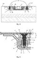
- the depth H (see figure 13 ) of the same abutment end 80 of the two adjustment bushes 84 is determined with respect to the outer surface 100A of the metal profile 100 with which the two flat fixing flanges 15 of the hinge body 11, 12 must be coplanar.
- a covering plate 40 is advantageously provided for, aimed to improve the appearance of the hinge 10 by concealing from view the screws and the seat in the hinge body 11, 12 of the articulation arm 13.
- the adjustment of the bushes 84 on the anchoring bodies 8 will in this case have to account for the thickness S' of this plate 40 and thus the depth of the abutment end 80 of the two adjustment bushes 84 will have to be adjusted in order to not only account for the thickness of the fixing flanges 15.
- the anchoring bodies 8 and the adjustment bushes 84 are in the form of substantially cylindrical elements, mechanically engaged with each other in a relationship of screw/nut screw type which allows, by rotating adjustment bush 84, making the abutment end 80 thereof project to a variable extent, hence this is movable, with respect to the relative anchoring body 8, which instead is fixed and integral with the bottom wall 3 of the shaped plate 2.
- the retainer 1 comprises screw fixing means 90 configured for fixing the hinge body 11, 12 in abutment against the abutment end 80 of the adjustment bushes 84, in particular in a manner such to retain the hinge body 11, 12 integral with the adjustment bushes 84 in the desired position defined by the abutment end 80 of the latter in accordance with that described above.
- the screw fixing means 90 are engaged with the anchoring bodies 8 or with the adjustment bushes 84 depending on the different embodiments described in detail hereinbelow.
- the screw fixing means 90 allow fixing, in a stopped manner, the hinge body 11, 12 to the retainer 1, maintaining it firmly in abutment against the abutment ends 80 of the adjustment bushes 84, after the latter have been arranged at the suitable height for arranging the hinge body 11, 12 coplanar with the outer surface 100A of the metal profile 100.
- each pair of elements formed by the anchoring body 8 and by the adjustment bush 84 defines an adjustment group with which a threaded hole 81, or nut screw, is associated (which thus, depending on the embodiment, can be made on the anchoring body 8 or on the adjustment bush 84) susceptible of receiving the engagement of a retaining screw 9 of the aforesaid screw fixing means 90 for the fixing of the hinge body 11, 12 to the retainer 1 and hence to the metal profile 100.
- each of the two anchoring bodies 8 is fixed to the bottom wall 3 protruding towards the interior of the containment tank, and is internally provided with the threaded hole 81 and externally provided with the first thread 83.
- each of the two corresponding adjustment bushes 84 is provided with a through hole 85 susceptible of being crossed by the retaining screw 9 and at least one portion thereof covered by the second thread 86.
- the latter is engaged with the first outer thread 83 of the corresponding anchoring body 8 in an adjustable manner such that by rotating the adjustment bush 84 it is possible to easily vary the height of the free abutment end 80 of the bush 84 on which the fixing flanges 15 of the hinge body 11, 12 are intended to be set.
- Each adjustment bush 84 is provided, for such purpose, with a female socket 87, for example obtained with a cavity of polygonal and in particular hexagonal shape, aligned with the through hole 85 thereof and susceptible of being engaged by a tool provided with a male head that is counter-shaped with respect to the female seat (e.g. an Allen wrench, not illustrated) in order to adjust by means of screwing/unscrewing the position of the adjustment bush 84 along the first thread 83 of the corresponding anchoring body 8, so as to consequently vary the height of the abutment end 80.
- a female socket 87 for example obtained with a cavity of polygonal and in particular hexagonal shape, aligned with the through hole 85 thereof and susceptible of being engaged by a tool provided with a male head that is counter-shaped with respect to the female seat (e.g. an Allen wrench, not illustrated) in order to adjust by means of screwing/unscrewing the position of the adjustment bush 84 along the first thread 83 of the corresponding anchoring body 8, so as to consequently vary the
- the anchoring bodies 8 can be advantageously fixed to the bottom wall 3 of the shaped plate 2 by means of welding (as illustrated in figure 3 ), riveting, pressure driving or by means of still other means, or they can be fixed to the bottom wall 3 since they are made integral with the same bottom wall 3 of the shaped plate 2, as illustrated in figure 8 .
- anchoring bodies 8 With the term "fixed” referred to the anchoring bodies 8, also anchoring bodies 8 must be intended which are not separate elements from the shaped plate 2, fixed to the bottom thereof, but rather are a portion thereof protruding internally or externally with respect to the tank of the shaped plate 2 as indicated in figures 7 and 8 .
- each anchoring body 8 is extended projecting outwards of the containment tank.
- the first inner thread 83 is in this case made within the anchoring body.
- the threaded holes 81 for engaging the retaining screws 9 aimed to retain the hinge bodies 11, 12 are made on the same adjustment bushes 84 starting from their abutment ends 80.
- the adjustment bushes 84 are provided with a stem 82 externally provided with the second thread 86 and engaged in the first thread 83 formed inside the anchoring body 8 projecting externally with respect to the tank of the shaped plate 2.
- the adjustment bush 84 defines, at a free end thereof, the abutment end 80 on which the fixing flanges 15 of the hinge body 11, 12 come to be set.
- each adjustment bush 84 is provided with a female socket 87 aligned with the threaded hole 81 and susceptible of being engaged by a tool provided with a male head that is counter-shaped with respect to the female seat in order to adjust, by means of screwing/unscrewing, the position of the adjustment bush 84 along the inner thread 83 of the corresponding anchoring body 8, so as to consequently vary the height of the abutment end 80.
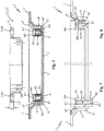
- a hinge assembly 50 for metal doors/windows illustrated in figures 9 and 10 .
- the door/window comprises a first profile 100' of the movable wing provided with at least one first opening 101', and at least one second profile 100" of the fixed frame provided with at least one second opening 101" aligned height-wise with the first opening 101'.
- the second profile 100" (of the fixed frame) is made of metal, while the first profile 100' (of the movable wing) can be made of a non-metallic material, e.g. wood (as in the example of figures 9 and 10 ) or it too can be made of metal material.
- a non-metallic material e.g. wood (as in the example of figures 9 and 10 ) or it too can be made of metal material.
- the assembly 50 comprises at least one hinge 10, preferably concealable/retractable, provided with two hinge bodies 11, 12 joined together by at least one articulation arm 13, and respectively insertable in the first and in the second opening 101', 101" of the two profiles 100', 100" of the movable wing and of the fixed frame.
- the assembly 50 also comprises at least one retainer 1 for each hinge 10 of the assembly 50 itself.
- the assembly 50 comprises, for each hinge 10, only one retainer 1 intended to be fixed to the second metal profile 100" of the fixed frame in order to connect the hinge body 12 to the latter, while the other hinge body 11 is connected directly to the first profile 100' of the movable wing.
- the assembly 50 comprises, for each hinge 10, two retainers 1, including a retainer 1 fixed to the second profile 100" of the fixed frame and the other retainer 1 fixed to the first profile 100' of the movable wing, in order to connect the hinge bodies 11, 12 to the corresponding profiles 100', 100".
- the metal profiles 100" (and possibly 100'), the concealable/retractable hinge 10 and the retainers 1 with the anchoring groups 8 are of the type already described above, hence for the sake of description simplicity the same reference numbers will be maintained.
- the shaped plate 2 of the retainer 1 is fixed inside the second metal profile 100" of the fixed frame at the second opening 101" for the embedded housing of the hinge body 12 of the hinge 10.
- the two shaped plates 2 of the two retainers 1 are as follows: one is fixed inside the first metal profile 100' of the movable wing and the other is fixed inside the second metal profile 100" of the fixed frame at the respective first and second opening 101', 101" for the embedded housing of the corresponding hinge body 11, 12 of the hinge 10.
- the shaped plate 2 defines a containment tank for the corresponding hinge body 12 (and possibly 11) and is provided with a bottom wall 3 facing the corresponding opening 101" (and possibly 101').
- the assembly 50 then provides for at least two anchoring bodies 8 for each shaped plate 2, fixed to the bottom wall 3 of the latter at the two lateral ends and each provided with a first thread 83.
- the assembly 50 comprises two adjustment bushes 84 for each shaped plate 2, protruding within the containment tank and each provided with an abutment end 80, which supports the corresponding hinge body 11, 12 in abutment and is mechanically associated with one of the anchoring bodies 8 by means of a second thread 86 adjustably engaged with the first thread 83 of the anchoring body 8 to vary the height of the abutment end 80 with respect to the bottom wall 3 of the shaped plate 2.
- each pair of elements formed by the anchoring body 8 and by the adjustment bush 84 defines an adjustment group with which a threaded hole 81 is associated (which thus, depending on the embodiment, can be made on the anchoring body 8 or on the adjustment bush 84), which is engaged by a retaining screw 9 associated with the head to the flanges of the hinge body 11, 12 so as to fix the same hinge body to the retainer 1 and hence to the metal profile 100.
- two or preferably three hinge assemblies 50 can be provided, placed at three different heights to rotatably support the door in a sufficiently distributed manner.
- forming the object of the present invention is a method for fixing a hinge 10, in particular of concealable/retractable type, on profiles 100 of metal doors/windows, which will be described hereinbelow by employing, for the sake of description simplicity, the same reference numbers used above with reference to the retainer 1 and to the assembly 50.
- the method, object of the invention employs at least one retainer 1 in accordance with the above description and operates according to the steps described hereinbelow.
- a step is provided for notching a metal profile 100 of a movable wing or of a fixed frame in order to make a shaped opening 101.
- a step takes place for fixing a shaped plate 2 within the metal profile 100 of the door/window at the shaped opening 101, with the bottom wall 3 of the shaped plate 2 which, through such fixing, comes to be situated embedded within the metal profile 100 facing the same shaped opening 101.
- the fixing step and the notching step can also be reversed in order of execution.
- the visible side of the fixing flanges 15 of the hinge body 11, 12 is advantageously obtained with a covering plate 40 having the object of concealing the screws and having a thickness indicated in figure 13 with S'.
- this coplanarity is attained by means of the aforesaid adjustment step by varying the screwing of the adjustment bush 84 up to placing the abutment end 80 thereof at a depth H with respect to the outer surface 100A of the metal profile 100 equal to the thickness S of the fixing flanges 15 of the hinge body 11, 12 and possibly added with the thickness S' of the covering plate 40 if present.
- the hinge body 11, 12 is inserted through the shaped opening 101 of the metal profile 100, in the containment tank of the shaped plate 2, with the fixing flanges 15 which are laid on the abutment ends 80 of the adjustment bushes 84 and with the visible side of the hinge body 11, 12 which is aligned with the outer surface 100A of the metal profile 100 of the door/window, due to the preceding adjustment step with the above-described screw/nut screw engagement between the adjustment bushes 84 and the anchoring bodies 8.
- the method in particular provides that the adjustment occurs by varying the screwing of the second threads 86 of the adjustment bushes 84 on the first threads 83 of the anchoring bodies 8 and the fixing of the hinge body 11, 12 to the retainer 1 occurs by means of the screwing of retaining screws 9 which cross through the through holes 150, 85 of the flanges 15 of the hinge body 11, 12 and of the adjustment bushes 84 up to being engaged in the threaded holes 81 of the anchoring bodies 8.
- the finding thus conceived therefore attains the pre-established objects.
Landscapes
- Engineering & Computer Science (AREA)
- Mechanical Engineering (AREA)
- Hinges (AREA)
Priority Applications (1)
| Application Number | Priority Date | Filing Date | Title |
|---|---|---|---|
| PL18174123T PL3406833T3 (pl) | 2017-05-24 | 2018-05-24 | Element ustalający do mocowania zawiasu na metalowych profilach drzwi/okna, zespół zawiasu do metalowych profili drzwi/okna oraz sposób mocowania zawiasu na metalowych profilach drzwi/okna |
Applications Claiming Priority (1)
| Application Number | Priority Date | Filing Date | Title |
|---|---|---|---|
| IT102017000056409A IT201700056409A1 (it) | 2017-05-24 | 2017-05-24 | Ritenuta per il fissaggio di una cerniera, in particolare a scomparsa, su profili di serramenti in metallo, assieme di incernieramento per profili di serramenti in metallo e metodo per il fissaggio di una cerniera, in particolare a scomparsa, su profili di serramenti in metallo |
Publications (2)
| Publication Number | Publication Date |
|---|---|
| EP3406833A1 true EP3406833A1 (fr) | 2018-11-28 |
| EP3406833B1 EP3406833B1 (fr) | 2020-01-22 |
Family
ID=60020457
Family Applications (1)
| Application Number | Title | Priority Date | Filing Date |
|---|---|---|---|
| EP18174123.2A Active EP3406833B1 (fr) | 2017-05-24 | 2018-05-24 | Dispositif de retenue pour fixer une charniere sur des profilés de porte / fenetre en métal, ensemble de charnière pour profilés de porte / fenêtre en métal et procédé pour fixer une charnière sur des profilés de porte / fenêtre en métal. |
Country Status (3)
| Country | Link |
|---|---|
| EP (1) | EP3406833B1 (fr) |
| IT (1) | IT201700056409A1 (fr) |
| PL (1) | PL3406833T3 (fr) |
Cited By (1)
| Publication number | Priority date | Publication date | Assignee | Title |
|---|---|---|---|---|
| CN114197990A (zh) * | 2021-12-01 | 2022-03-18 | 门联(上海)智能系统工程有限公司 | 一种钢结构门窗 |
Citations (2)
| Publication number | Priority date | Publication date | Assignee | Title |
|---|---|---|---|---|
| DE102015112640B3 (de) * | 2015-07-31 | 2016-01-21 | Simonswerk, Gesellschaft mit beschränkter Haftung | Türband für eine verdeckte Anordnung zwischen Türflügel und Türzarge |
| WO2017065699A1 (fr) * | 2015-10-12 | 2017-04-20 | Kuantica S.R.L. | Charnière dissimulée invisible à structure améliorée pour portes |
-
2017
- 2017-05-24 IT IT102017000056409A patent/IT201700056409A1/it unknown
-
2018
- 2018-05-24 PL PL18174123T patent/PL3406833T3/pl unknown
- 2018-05-24 EP EP18174123.2A patent/EP3406833B1/fr active Active
Patent Citations (2)
| Publication number | Priority date | Publication date | Assignee | Title |
|---|---|---|---|---|
| DE102015112640B3 (de) * | 2015-07-31 | 2016-01-21 | Simonswerk, Gesellschaft mit beschränkter Haftung | Türband für eine verdeckte Anordnung zwischen Türflügel und Türzarge |
| WO2017065699A1 (fr) * | 2015-10-12 | 2017-04-20 | Kuantica S.R.L. | Charnière dissimulée invisible à structure améliorée pour portes |
Cited By (2)
| Publication number | Priority date | Publication date | Assignee | Title |
|---|---|---|---|---|
| CN114197990A (zh) * | 2021-12-01 | 2022-03-18 | 门联(上海)智能系统工程有限公司 | 一种钢结构门窗 |
| CN114197990B (zh) * | 2021-12-01 | 2023-10-31 | 门联(上海)智能系统工程有限公司 | 一种钢结构门窗 |
Also Published As
| Publication number | Publication date |
|---|---|
| EP3406833B1 (fr) | 2020-01-22 |
| IT201700056409A1 (it) | 2018-11-24 |
| PL3406833T3 (pl) | 2020-06-29 |
Similar Documents
| Publication | Publication Date | Title |
|---|---|---|
| US4785498A (en) | Door and window hinge which is adjustable during and after installation | |
| KR102525845B1 (ko) | 슬라이딩 도어를 위한 판유리 고정 장치 | |
| EP0992647B1 (fr) | Charnière réglable pour cadre de porte | |
| US10938190B1 (en) | Seismic cabinet mounts | |
| EP3406833B1 (fr) | Dispositif de retenue pour fixer une charniere sur des profilés de porte / fenetre en métal, ensemble de charnière pour profilés de porte / fenêtre en métal et procédé pour fixer une charnière sur des profilés de porte / fenêtre en métal. | |
| DE20005982U1 (de) | Profilelement für eine Duschabtrennung | |
| US2761185A (en) | Blind or like slat or louver assembly and method of assembling | |
| US20080036342A1 (en) | Configurations and Methods for Modular Cabinetry | |
| EP3005904B1 (fr) | Structure de support avec profil support et bras supports | |
| US3601430A (en) | Joints between structural members | |
| US11828102B2 (en) | Adjustable packer apparatus | |
| US11891851B2 (en) | Door-ready molding | |
| US3056475A (en) | Sanitary partitioning cubicles | |
| US20050091924A1 (en) | Shutters for door and window frames and methods of producing shutters for door and window frames | |
| EP3264941B1 (fr) | Systèmes d'étagères flottantes réglables | |
| WO2006112799A1 (fr) | Element de suspension pour la fixation murale reglable de meuble, notamment d'un meuble suspendu et procedure de montage de meuble sur celui-ci | |
| EP2275003A1 (fr) | Unité de mobilier du type bibliothèque avec éléments réglables | |
| EP2644818A1 (fr) | Pièce de liaison | |
| EP2028336A1 (fr) | Ensemble ferrures et profils pour réalisation d'une structure de support de portes d'armoire et d'articles similaires | |
| EP3441550B1 (fr) | Charnière invisible | |
| US1769424A (en) | Stiffener and aligner for hollow metal doors and casement windows | |
| JP3021988B2 (ja) | 安全柵 | |
| JP4811002B2 (ja) | 組立式デスクにおける支柱取付装置 | |
| JP6861576B2 (ja) | 建具 | |
| JP7638128B2 (ja) | ドア枠 |
Legal Events
| Date | Code | Title | Description |
|---|---|---|---|
| PUAI | Public reference made under article 153(3) epc to a published international application that has entered the european phase |
Free format text: ORIGINAL CODE: 0009012 |
|
| STAA | Information on the status of an ep patent application or granted ep patent |
Free format text: STATUS: THE APPLICATION HAS BEEN PUBLISHED |
|
| AK | Designated contracting states |
Kind code of ref document: A1 Designated state(s): AL AT BE BG CH CY CZ DE DK EE ES FI FR GB GR HR HU IE IS IT LI LT LU LV MC MK MT NL NO PL PT RO RS SE SI SK SM TR |
|
| AX | Request for extension of the european patent |
Extension state: BA ME |
|
| STAA | Information on the status of an ep patent application or granted ep patent |
Free format text: STATUS: REQUEST FOR EXAMINATION WAS MADE |
|
| 17P | Request for examination filed |
Effective date: 20190528 |
|
| RBV | Designated contracting states (corrected) |
Designated state(s): AL AT BE BG CH CY CZ DE DK EE ES FI FR GB GR HR HU IE IS IT LI LT LU LV MC MK MT NL NO PL PT RO RS SE SI SK SM TR |
|
| RIC1 | Information provided on ipc code assigned before grant |
Ipc: E05D 5/02 20060101ALI20190619BHEP Ipc: E05D 3/06 20060101ALN20190619BHEP Ipc: E05D 7/04 20060101AFI20190619BHEP |
|
| GRAP | Despatch of communication of intention to grant a patent |
Free format text: ORIGINAL CODE: EPIDOSNIGR1 |
|
| STAA | Information on the status of an ep patent application or granted ep patent |
Free format text: STATUS: GRANT OF PATENT IS INTENDED |
|
| INTG | Intention to grant announced |
Effective date: 20190806 |
|
| GRAS | Grant fee paid |
Free format text: ORIGINAL CODE: EPIDOSNIGR3 |
|
| GRAA | (expected) grant |
Free format text: ORIGINAL CODE: 0009210 |
|
| STAA | Information on the status of an ep patent application or granted ep patent |
Free format text: STATUS: THE PATENT HAS BEEN GRANTED |
|
| AK | Designated contracting states |
Kind code of ref document: B1 Designated state(s): AL AT BE BG CH CY CZ DE DK EE ES FI FR GB GR HR HU IE IS IT LI LT LU LV MC MK MT NL NO PL PT RO RS SE SI SK SM TR |
|
| REG | Reference to a national code |
Ref country code: GB Ref legal event code: FG4D |
|
| REG | Reference to a national code |
Ref country code: CH Ref legal event code: EP |
|
| REG | Reference to a national code |
Ref country code: DE Ref legal event code: R096 Ref document number: 602018002084 Country of ref document: DE |
|
| REG | Reference to a national code |
Ref country code: AT Ref legal event code: REF Ref document number: 1226997 Country of ref document: AT Kind code of ref document: T Effective date: 20200215 |
|
| REG | Reference to a national code |
Ref country code: IE Ref legal event code: FG4D |
|
| REG | Reference to a national code |
Ref country code: NL Ref legal event code: MP Effective date: 20200122 |
|
| REG | Reference to a national code |
Ref country code: LT Ref legal event code: MG4D |
|
| PG25 | Lapsed in a contracting state [announced via postgrant information from national office to epo] |
Ref country code: NL Free format text: LAPSE BECAUSE OF FAILURE TO SUBMIT A TRANSLATION OF THE DESCRIPTION OR TO PAY THE FEE WITHIN THE PRESCRIBED TIME-LIMIT Effective date: 20200122 Ref country code: PT Free format text: LAPSE BECAUSE OF FAILURE TO SUBMIT A TRANSLATION OF THE DESCRIPTION OR TO PAY THE FEE WITHIN THE PRESCRIBED TIME-LIMIT Effective date: 20200614 Ref country code: RS Free format text: LAPSE BECAUSE OF FAILURE TO SUBMIT A TRANSLATION OF THE DESCRIPTION OR TO PAY THE FEE WITHIN THE PRESCRIBED TIME-LIMIT Effective date: 20200122 Ref country code: FI Free format text: LAPSE BECAUSE OF FAILURE TO SUBMIT A TRANSLATION OF THE DESCRIPTION OR TO PAY THE FEE WITHIN THE PRESCRIBED TIME-LIMIT Effective date: 20200122 Ref country code: NO Free format text: LAPSE BECAUSE OF FAILURE TO SUBMIT A TRANSLATION OF THE DESCRIPTION OR TO PAY THE FEE WITHIN THE PRESCRIBED TIME-LIMIT Effective date: 20200422 |
|
| PG25 | Lapsed in a contracting state [announced via postgrant information from national office to epo] |
Ref country code: HR Free format text: LAPSE BECAUSE OF FAILURE TO SUBMIT A TRANSLATION OF THE DESCRIPTION OR TO PAY THE FEE WITHIN THE PRESCRIBED TIME-LIMIT Effective date: 20200122 Ref country code: BG Free format text: LAPSE BECAUSE OF FAILURE TO SUBMIT A TRANSLATION OF THE DESCRIPTION OR TO PAY THE FEE WITHIN THE PRESCRIBED TIME-LIMIT Effective date: 20200422 Ref country code: GR Free format text: LAPSE BECAUSE OF FAILURE TO SUBMIT A TRANSLATION OF THE DESCRIPTION OR TO PAY THE FEE WITHIN THE PRESCRIBED TIME-LIMIT Effective date: 20200423 Ref country code: IS Free format text: LAPSE BECAUSE OF FAILURE TO SUBMIT A TRANSLATION OF THE DESCRIPTION OR TO PAY THE FEE WITHIN THE PRESCRIBED TIME-LIMIT Effective date: 20200522 Ref country code: SE Free format text: LAPSE BECAUSE OF FAILURE TO SUBMIT A TRANSLATION OF THE DESCRIPTION OR TO PAY THE FEE WITHIN THE PRESCRIBED TIME-LIMIT Effective date: 20200122 Ref country code: LV Free format text: LAPSE BECAUSE OF FAILURE TO SUBMIT A TRANSLATION OF THE DESCRIPTION OR TO PAY THE FEE WITHIN THE PRESCRIBED TIME-LIMIT Effective date: 20200122 |
|
| REG | Reference to a national code |
Ref country code: DE Ref legal event code: R097 Ref document number: 602018002084 Country of ref document: DE |
|
| PG25 | Lapsed in a contracting state [announced via postgrant information from national office to epo] |
Ref country code: DK Free format text: LAPSE BECAUSE OF FAILURE TO SUBMIT A TRANSLATION OF THE DESCRIPTION OR TO PAY THE FEE WITHIN THE PRESCRIBED TIME-LIMIT Effective date: 20200122 Ref country code: LT Free format text: LAPSE BECAUSE OF FAILURE TO SUBMIT A TRANSLATION OF THE DESCRIPTION OR TO PAY THE FEE WITHIN THE PRESCRIBED TIME-LIMIT Effective date: 20200122 Ref country code: SM Free format text: LAPSE BECAUSE OF FAILURE TO SUBMIT A TRANSLATION OF THE DESCRIPTION OR TO PAY THE FEE WITHIN THE PRESCRIBED TIME-LIMIT Effective date: 20200122 Ref country code: EE Free format text: LAPSE BECAUSE OF FAILURE TO SUBMIT A TRANSLATION OF THE DESCRIPTION OR TO PAY THE FEE WITHIN THE PRESCRIBED TIME-LIMIT Effective date: 20200122 Ref country code: SK Free format text: LAPSE BECAUSE OF FAILURE TO SUBMIT A TRANSLATION OF THE DESCRIPTION OR TO PAY THE FEE WITHIN THE PRESCRIBED TIME-LIMIT Effective date: 20200122 Ref country code: RO Free format text: LAPSE BECAUSE OF FAILURE TO SUBMIT A TRANSLATION OF THE DESCRIPTION OR TO PAY THE FEE WITHIN THE PRESCRIBED TIME-LIMIT Effective date: 20200122 Ref country code: CZ Free format text: LAPSE BECAUSE OF FAILURE TO SUBMIT A TRANSLATION OF THE DESCRIPTION OR TO PAY THE FEE WITHIN THE PRESCRIBED TIME-LIMIT Effective date: 20200122 Ref country code: ES Free format text: LAPSE BECAUSE OF FAILURE TO SUBMIT A TRANSLATION OF THE DESCRIPTION OR TO PAY THE FEE WITHIN THE PRESCRIBED TIME-LIMIT Effective date: 20200122 |
|
| REG | Reference to a national code |
Ref country code: AT Ref legal event code: MK05 Ref document number: 1226997 Country of ref document: AT Kind code of ref document: T Effective date: 20200122 |
|
| PLBE | No opposition filed within time limit |
Free format text: ORIGINAL CODE: 0009261 |
|
| STAA | Information on the status of an ep patent application or granted ep patent |
Free format text: STATUS: NO OPPOSITION FILED WITHIN TIME LIMIT |
|
| 26N | No opposition filed |
Effective date: 20201023 |
|
| PG25 | Lapsed in a contracting state [announced via postgrant information from national office to epo] |
Ref country code: AT Free format text: LAPSE BECAUSE OF FAILURE TO SUBMIT A TRANSLATION OF THE DESCRIPTION OR TO PAY THE FEE WITHIN THE PRESCRIBED TIME-LIMIT Effective date: 20200122 Ref country code: MC Free format text: LAPSE BECAUSE OF FAILURE TO SUBMIT A TRANSLATION OF THE DESCRIPTION OR TO PAY THE FEE WITHIN THE PRESCRIBED TIME-LIMIT Effective date: 20200122 |
|
| PG25 | Lapsed in a contracting state [announced via postgrant information from national office to epo] |
Ref country code: SI Free format text: LAPSE BECAUSE OF FAILURE TO SUBMIT A TRANSLATION OF THE DESCRIPTION OR TO PAY THE FEE WITHIN THE PRESCRIBED TIME-LIMIT Effective date: 20200122 |
|
| REG | Reference to a national code |
Ref country code: BE Ref legal event code: MM Effective date: 20200531 |
|
| PG25 | Lapsed in a contracting state [announced via postgrant information from national office to epo] |
Ref country code: LU Free format text: LAPSE BECAUSE OF NON-PAYMENT OF DUE FEES Effective date: 20200524 |
|
| PG25 | Lapsed in a contracting state [announced via postgrant information from national office to epo] |
Ref country code: IE Free format text: LAPSE BECAUSE OF NON-PAYMENT OF DUE FEES Effective date: 20200524 Ref country code: FR Free format text: LAPSE BECAUSE OF NON-PAYMENT OF DUE FEES Effective date: 20200531 |
|
| PG25 | Lapsed in a contracting state [announced via postgrant information from national office to epo] |
Ref country code: BE Free format text: LAPSE BECAUSE OF NON-PAYMENT OF DUE FEES Effective date: 20200531 |
|
| REG | Reference to a national code |
Ref country code: CH Ref legal event code: PL |
|
| PG25 | Lapsed in a contracting state [announced via postgrant information from national office to epo] |
Ref country code: CH Free format text: LAPSE BECAUSE OF NON-PAYMENT OF DUE FEES Effective date: 20210531 Ref country code: LI Free format text: LAPSE BECAUSE OF NON-PAYMENT OF DUE FEES Effective date: 20210531 |
|
| PG25 | Lapsed in a contracting state [announced via postgrant information from national office to epo] |
Ref country code: TR Free format text: LAPSE BECAUSE OF FAILURE TO SUBMIT A TRANSLATION OF THE DESCRIPTION OR TO PAY THE FEE WITHIN THE PRESCRIBED TIME-LIMIT Effective date: 20200122 Ref country code: MT Free format text: LAPSE BECAUSE OF FAILURE TO SUBMIT A TRANSLATION OF THE DESCRIPTION OR TO PAY THE FEE WITHIN THE PRESCRIBED TIME-LIMIT Effective date: 20200122 Ref country code: CY Free format text: LAPSE BECAUSE OF FAILURE TO SUBMIT A TRANSLATION OF THE DESCRIPTION OR TO PAY THE FEE WITHIN THE PRESCRIBED TIME-LIMIT Effective date: 20200122 |
|
| PG25 | Lapsed in a contracting state [announced via postgrant information from national office to epo] |
Ref country code: MK Free format text: LAPSE BECAUSE OF FAILURE TO SUBMIT A TRANSLATION OF THE DESCRIPTION OR TO PAY THE FEE WITHIN THE PRESCRIBED TIME-LIMIT Effective date: 20200122 Ref country code: AL Free format text: LAPSE BECAUSE OF FAILURE TO SUBMIT A TRANSLATION OF THE DESCRIPTION OR TO PAY THE FEE WITHIN THE PRESCRIBED TIME-LIMIT Effective date: 20200122 |
|
| GBPC | Gb: european patent ceased through non-payment of renewal fee |
Effective date: 20220524 |
|
| PG25 | Lapsed in a contracting state [announced via postgrant information from national office to epo] |
Ref country code: GB Free format text: LAPSE BECAUSE OF NON-PAYMENT OF DUE FEES Effective date: 20220524 |
|
| P01 | Opt-out of the competence of the unified patent court (upc) registered |
Effective date: 20230302 |
|
| PGFP | Annual fee paid to national office [announced via postgrant information from national office to epo] |
Ref country code: PL Payment date: 20250425 Year of fee payment: 8 Ref country code: DE Payment date: 20250521 Year of fee payment: 8 |
|
| PGFP | Annual fee paid to national office [announced via postgrant information from national office to epo] |
Ref country code: IT Payment date: 20250528 Year of fee payment: 8 |