EP3406880A1 - Procédé et dispositif de commande d'une soupape d'évacuation - Google Patents
Procédé et dispositif de commande d'une soupape d'évacuation Download PDFInfo
- Publication number
- EP3406880A1 EP3406880A1 EP16886516.0A EP16886516A EP3406880A1 EP 3406880 A1 EP3406880 A1 EP 3406880A1 EP 16886516 A EP16886516 A EP 16886516A EP 3406880 A1 EP3406880 A1 EP 3406880A1
- Authority
- EP
- European Patent Office
- Prior art keywords
- gate valve
- waste gate
- opening degree
- idling
- time
- Prior art date
- Legal status (The legal status is an assumption and is not a legal conclusion. Google has not performed a legal analysis and makes no representation as to the accuracy of the status listed.)
- Granted
Links
Images

Classifications
-
- F—MECHANICAL ENGINEERING; LIGHTING; HEATING; WEAPONS; BLASTING
- F01—MACHINES OR ENGINES IN GENERAL; ENGINE PLANTS IN GENERAL; STEAM ENGINES
- F01D—NON-POSITIVE DISPLACEMENT MACHINES OR ENGINES, e.g. STEAM TURBINES
- F01D17/00—Regulating or controlling by varying flow
- F01D17/10—Final actuators
- F01D17/105—Final actuators by passing part of the fluid
-
- F—MECHANICAL ENGINEERING; LIGHTING; HEATING; WEAPONS; BLASTING
- F02—COMBUSTION ENGINES; HOT-GAS OR COMBUSTION-PRODUCT ENGINE PLANTS
- F02B—INTERNAL-COMBUSTION PISTON ENGINES; COMBUSTION ENGINES IN GENERAL
- F02B37/00—Engines characterised by provision of pumps driven at least for part of the time by exhaust
- F02B37/12—Control of the pumps
- F02B37/18—Control of the pumps by bypassing exhaust from the inlet to the outlet of turbine or to the atmosphere
-
- F—MECHANICAL ENGINEERING; LIGHTING; HEATING; WEAPONS; BLASTING
- F02—COMBUSTION ENGINES; HOT-GAS OR COMBUSTION-PRODUCT ENGINE PLANTS
- F02B—INTERNAL-COMBUSTION PISTON ENGINES; COMBUSTION ENGINES IN GENERAL
- F02B37/00—Engines characterised by provision of pumps driven at least for part of the time by exhaust
- F02B37/12—Control of the pumps
- F02B37/18—Control of the pumps by bypassing exhaust from the inlet to the outlet of turbine or to the atmosphere
- F02B37/183—Arrangements of bypass valves or actuators therefor
- F02B37/186—Arrangements of actuators or linkage for bypass valves
-
- F—MECHANICAL ENGINEERING; LIGHTING; HEATING; WEAPONS; BLASTING
- F02—COMBUSTION ENGINES; HOT-GAS OR COMBUSTION-PRODUCT ENGINE PLANTS
- F02C—GAS-TURBINE PLANTS; AIR INTAKES FOR JET-PROPULSION PLANTS; CONTROLLING FUEL SUPPLY IN AIR-BREATHING JET-PROPULSION PLANTS
- F02C6/00—Plural gas-turbine plants; Combinations of gas-turbine plants with other apparatus; Adaptations of gas-turbine plants for special use
- F02C6/04—Gas-turbine plants providing heated or pressurised working fluid for other apparatus, e.g. without mechanical power output
- F02C6/10—Gas-turbine plants providing heated or pressurised working fluid for other apparatus, e.g. without mechanical power output supplying working fluid to a user, e.g. a chemical process, which returns working fluid to a turbine of the plant
- F02C6/12—Turbochargers, i.e. plants for augmenting mechanical power output of internal-combustion piston engines by increase of charge pressure
-
- F—MECHANICAL ENGINEERING; LIGHTING; HEATING; WEAPONS; BLASTING
- F02—COMBUSTION ENGINES; HOT-GAS OR COMBUSTION-PRODUCT ENGINE PLANTS
- F02D—CONTROLLING COMBUSTION ENGINES
- F02D37/00—Non-electrical conjoint control of two or more functions of engines, not otherwise provided for
- F02D37/02—Non-electrical conjoint control of two or more functions of engines, not otherwise provided for one of the functions being ignition
-
- F—MECHANICAL ENGINEERING; LIGHTING; HEATING; WEAPONS; BLASTING
- F02—COMBUSTION ENGINES; HOT-GAS OR COMBUSTION-PRODUCT ENGINE PLANTS
- F02D—CONTROLLING COMBUSTION ENGINES
- F02D41/00—Electrical control of supply of combustible mixture or its constituents
- F02D41/0002—Controlling intake air
- F02D41/0007—Controlling intake air for control of turbo-charged or super-charged engines
-
- F—MECHANICAL ENGINEERING; LIGHTING; HEATING; WEAPONS; BLASTING
- F02—COMBUSTION ENGINES; HOT-GAS OR COMBUSTION-PRODUCT ENGINE PLANTS
- F02D—CONTROLLING COMBUSTION ENGINES
- F02D41/00—Electrical control of supply of combustible mixture or its constituents
- F02D41/02—Circuit arrangements for generating control signals
- F02D41/04—Introducing corrections for particular operating conditions
- F02D41/06—Introducing corrections for particular operating conditions for engine starting or warming up
- F02D41/068—Introducing corrections for particular operating conditions for engine starting or warming up for warming-up
-
- F—MECHANICAL ENGINEERING; LIGHTING; HEATING; WEAPONS; BLASTING
- F02—COMBUSTION ENGINES; HOT-GAS OR COMBUSTION-PRODUCT ENGINE PLANTS
- F02D—CONTROLLING COMBUSTION ENGINES
- F02D41/00—Electrical control of supply of combustible mixture or its constituents
- F02D41/02—Circuit arrangements for generating control signals
- F02D41/04—Introducing corrections for particular operating conditions
- F02D41/08—Introducing corrections for particular operating conditions for idling
-
- F—MECHANICAL ENGINEERING; LIGHTING; HEATING; WEAPONS; BLASTING
- F02—COMBUSTION ENGINES; HOT-GAS OR COMBUSTION-PRODUCT ENGINE PLANTS
- F02P—IGNITION, OTHER THAN COMPRESSION IGNITION, FOR INTERNAL-COMBUSTION ENGINES; TESTING OF IGNITION TIMING IN COMPRESSION-IGNITION ENGINES
- F02P5/00—Advancing or retarding ignition; Control therefor
- F02P5/04—Advancing or retarding ignition; Control therefor automatically, as a function of the working conditions of the engine or vehicle or of the atmospheric conditions
-
- F—MECHANICAL ENGINEERING; LIGHTING; HEATING; WEAPONS; BLASTING
- F02—COMBUSTION ENGINES; HOT-GAS OR COMBUSTION-PRODUCT ENGINE PLANTS
- F02P—IGNITION, OTHER THAN COMPRESSION IGNITION, FOR INTERNAL-COMBUSTION ENGINES; TESTING OF IGNITION TIMING IN COMPRESSION-IGNITION ENGINES
- F02P5/00—Advancing or retarding ignition; Control therefor
- F02P5/04—Advancing or retarding ignition; Control therefor automatically, as a function of the working conditions of the engine or vehicle or of the atmospheric conditions
- F02P5/045—Advancing or retarding ignition; Control therefor automatically, as a function of the working conditions of the engine or vehicle or of the atmospheric conditions combined with electronic control of other engine functions, e.g. fuel injection
-
- F—MECHANICAL ENGINEERING; LIGHTING; HEATING; WEAPONS; BLASTING
- F02—COMBUSTION ENGINES; HOT-GAS OR COMBUSTION-PRODUCT ENGINE PLANTS
- F02P—IGNITION, OTHER THAN COMPRESSION IGNITION, FOR INTERNAL-COMBUSTION ENGINES; TESTING OF IGNITION TIMING IN COMPRESSION-IGNITION ENGINES
- F02P5/00—Advancing or retarding ignition; Control therefor
- F02P5/04—Advancing or retarding ignition; Control therefor automatically, as a function of the working conditions of the engine or vehicle or of the atmospheric conditions
- F02P5/145—Advancing or retarding ignition; Control therefor automatically, as a function of the working conditions of the engine or vehicle or of the atmospheric conditions using electrical means
- F02P5/15—Digital data processing
- F02P5/1502—Digital data processing using one central computing unit
- F02P5/1508—Digital data processing using one central computing unit with particular means during idling
-
- F—MECHANICAL ENGINEERING; LIGHTING; HEATING; WEAPONS; BLASTING
- F02—COMBUSTION ENGINES; HOT-GAS OR COMBUSTION-PRODUCT ENGINE PLANTS
- F02D—CONTROLLING COMBUSTION ENGINES
- F02D2200/00—Input parameters for engine control
- F02D2200/60—Input parameters for engine control said parameters being related to the driver demands or status
- F02D2200/602—Pedal position
-
- F—MECHANICAL ENGINEERING; LIGHTING; HEATING; WEAPONS; BLASTING
- F02—COMBUSTION ENGINES; HOT-GAS OR COMBUSTION-PRODUCT ENGINE PLANTS
- F02D—CONTROLLING COMBUSTION ENGINES
- F02D2250/00—Engine control related to specific problems or objectives
- F02D2250/18—Control of the engine output torque
-
- F—MECHANICAL ENGINEERING; LIGHTING; HEATING; WEAPONS; BLASTING
- F02—COMBUSTION ENGINES; HOT-GAS OR COMBUSTION-PRODUCT ENGINE PLANTS
- F02D—CONTROLLING COMBUSTION ENGINES
- F02D41/00—Electrical control of supply of combustible mixture or its constituents
- F02D41/02—Circuit arrangements for generating control signals
- F02D41/04—Introducing corrections for particular operating conditions
- F02D41/08—Introducing corrections for particular operating conditions for idling
- F02D41/086—Introducing corrections for particular operating conditions for idling taking into account the temperature of the engine
-
- F—MECHANICAL ENGINEERING; LIGHTING; HEATING; WEAPONS; BLASTING
- F05—INDEXING SCHEMES RELATING TO ENGINES OR PUMPS IN VARIOUS SUBCLASSES OF CLASSES F01-F04
- F05D—INDEXING SCHEME FOR ASPECTS RELATING TO NON-POSITIVE-DISPLACEMENT MACHINES OR ENGINES, GAS-TURBINES OR JET-PROPULSION PLANTS
- F05D2220/00—Application
- F05D2220/40—Application in turbochargers
-
- Y—GENERAL TAGGING OF NEW TECHNOLOGICAL DEVELOPMENTS; GENERAL TAGGING OF CROSS-SECTIONAL TECHNOLOGIES SPANNING OVER SEVERAL SECTIONS OF THE IPC; TECHNICAL SUBJECTS COVERED BY FORMER USPC CROSS-REFERENCE ART COLLECTIONS [XRACs] AND DIGESTS
- Y02—TECHNOLOGIES OR APPLICATIONS FOR MITIGATION OR ADAPTATION AGAINST CLIMATE CHANGE
- Y02T—CLIMATE CHANGE MITIGATION TECHNOLOGIES RELATED TO TRANSPORTATION
- Y02T10/00—Road transport of goods or passengers
- Y02T10/10—Internal combustion engine [ICE] based vehicles
- Y02T10/12—Improving ICE efficiencies
-
- Y—GENERAL TAGGING OF NEW TECHNOLOGICAL DEVELOPMENTS; GENERAL TAGGING OF CROSS-SECTIONAL TECHNOLOGIES SPANNING OVER SEVERAL SECTIONS OF THE IPC; TECHNICAL SUBJECTS COVERED BY FORMER USPC CROSS-REFERENCE ART COLLECTIONS [XRACs] AND DIGESTS
- Y02—TECHNOLOGIES OR APPLICATIONS FOR MITIGATION OR ADAPTATION AGAINST CLIMATE CHANGE
- Y02T—CLIMATE CHANGE MITIGATION TECHNOLOGIES RELATED TO TRANSPORTATION
- Y02T10/00—Road transport of goods or passengers
- Y02T10/10—Internal combustion engine [ICE] based vehicles
- Y02T10/40—Engine management systems
Definitions
- This invention relates to valve opening control of a waste gate valve which is provided to a turbocharger.
- a turbocharger used for supercharging of an internal combustion engine is provided with a waste gate valve at a turbine part which is configured so as to bypass a part of exhaust flow without passing through a turbine wheel, for supercharging pressure control.
- a so-called swing type mechanism is disclosed in which the linear motion of a rod of an electric actuator is converted to the rotational motion of a rotation shaft through a link and then a poppet type valve body which is supported on the distal end of an arm fixed to the rotation shaft oscillates.
- the opening degree of the waste gate valve is controlled to full opening to reduce exhaust resistance, and a part of the exhaust flow passes through the periphery of the valve body.
- Patent Document 1 Japanese Patent Application Publication 2015-48837
- the present invention is one which controls the opening degree of a waste gate valve, at the time of an idling in a state in which an internal combustion engine is cold or at the time of deceleration.
- the opening degree of the waste gate valve controls the opening degree of the waste gate valve to be small, the amount of an exhaust flow which passes through the periphery of a valve body of the waste gate valve is reduced, and thereby the movement of the valve body caused by exhaust pulsation and pressure fluctuation is suppressed. Consequently, abnormal sound caused by clearance hardly occurs.
- the present invention it is possible to suppress the occurrence of the abnormal sound in the waste gate valve at the time of the idling in the engine cold state, in which the exhaust pulsation becomes large, or at the time of the deceleration.
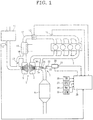
- FIG. 1 is a schematic explanatory drawing showing the system configuration of an embodiment of the present invention.
- An exhaust passage 2 of an internal combustion engine 1 that is a spark ignition type gasoline engine is disposed with an exhaust gas turbine 4 of a turbocharger 3, and on its downstream side, a catalyst converter 6 in which, for example, a three way catalyst is used is disposed.
- An exhaust muffler which is not shown in the drawings is provided on the further downstream side of exhaust passage 2, and exhaust passage 2 is opened outside via the exhaust muffler.
- Exhaust gas turbine 4 is provided with a waste gate valve 7 for supercharging pressure control.
- internal combustion engine 1 has, for example, a direct injection type configuration, and a fuel injection valve for injecting fuel into cylinders, which is not shown in the drawings, is provided in each cylinder, and an ignition plug which is not shown in the drawings is provided in each of the cylinders.
- Internal combustion engine 1 is not limited to the direct injection type, and may be a port injection type fuel injection device.
- An intake passage 10 of internal combustion engine 1 is disposed with an air cleaner 11, an air flow meter 12 and a throttle valve 13 arranged in this order from the upstream side.
- a compressor 5 of turbocharger 3 is disposed between air flow meter 12 and throttle valve 13.
- a water-cooled type or an air-cooled type intercooler 14 is interposed between compressor 5 and throttle valve 13.
- intake passage 10 is provided with a recirculation passage 16 which communicates between the upstream side and the downstream side of compressor 5.
- This recirculation passage 16 is provided with a recirculation valve 17.
- This recirculation valve 17 has a function of circulating intake air by opening the valve at the time of deceleration when throttle valve 13 is suddenly closed.
- a supercharging pressure sensor 15 for detecting supercharging pressure is disposed on the downstream side of throttle valve 13 of intake passage 10.
- Waste gate valve 7 has a configuration in which the opening degree of waste gate valve 7 is controlled by an electric actuator 20, and a position sensor 21 is included in electric actuator 20 to detect an actual opening degree.
- electric actuator 20 outputs the rotation of an electric motor as the movement in the axial direction of a rod 22 by a ball screw mechanism, and position sensor 21 detects the axial direction position of rod 22 with respect to the case of the actuator.
- Rod 22 is linked to a poppet type valve body 7a of waste gate valve 7 via a link 23 and an arm 24.
- the operation of electric actuator 20 is controlled by an engine controller 25 which performs various kinds of control of internal combustion engine 1.
- detection signals of sensors such as a cooling water temperature sensor 26 which detects a cooling water temperature TW of internal combustion engine 1, an accelerator opening degree sensor 27 which detects an accelerator depressing amount which is not shown in the drawings, that is, an accelerator opening degree APO, a crank angle sensor 28 which detects a rotation speed Ne of internal combustion engine 1 and an atmospheric pressure sensor 29 which detects an atmospheric pressure ATM, are input to engine controller 25.
- the opening degree of throttle valve 13 the fuel injection amount of the fuel injection valves which are not shown in the drawings and the ignition timing of the ignition plugs which is not shown in the drawings are also controlled by engine controller 25.
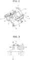
- FIG. 2 shows a more specific configuration example of waste gate valve 7 provided to exhaust gas turbine 4 of turbocharger 3.
- valve body 7a of waste gate valve 7 is positioned at an exhaust outlet portion 33 of a turbine housing 31 having a scroll portion 32, and is configured to open and close a bypass passage 34 (schematically shown in FIG. 1 ) from exhaust outlet portion 33 side, which communicates the upstream side part of scroll portion 32 with exhaust outlet portion 33.
- This waste gate valve 7 has a so-called swing type configuration, and valve body 7a is supported on the distal end of arm 24 having a shaft portion 24a.
- Shaft portion 24a is rotatably supported on turbine housing 31, and one end of link 23 is fixed to the base end of shaft portion 24a which is exposed to the outer surface of turbine housing 31.
- Rod 22 of electric actuator 20 for detail, an intermediate rod 22a is connected to the other end of link 23 via a pin 35.
- the basic configuration of the swing type waste gate valve is publicly known by, for example, Japanese Patent Application Publication No. 2014-58894 .
- arm 24 oscillates with shaft portion 24a as a center by the axial direction movement of rod 22 of electric actuator 20, and with this, circular valve body 7a opens and closes the distal end opening of bypass passage 34.
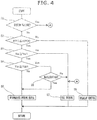
- FIG. 3 shows an example of the attachment structure of valve body 7a in the distal end of arm 24.
- a shaft portion 7b in the center of valve body 7a penetrates an attachment hole 24b of arm 24, and is prevented from coming out by attaching a ring-shaped fixing member 36 to a small diameter portion 7c at the distal end of shaft portion 7b.
- small clearances exist between arm 24 and valve body 7a and between shaft portion 7b and the inner circumferential surface of attachment hole 24b, and consequently, there is possibility that abnormal sound occurs caused by vibration.
- clearance also exists at the connection part between link 23 and rod 22, and consequently, this part can be an abnormal sound occurrence part.
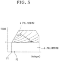
- FIG. 4 is a flow chart showing a flow of the process of the opening degree control of waste gate valve 7 which is executed by the above engine controller 25 that corresponds to a control section.
- a step 1 it is judged whether or not a system is in a system failure state based on a self-diagnostic result of the system which is executed in other control routines.
- some emergency abnormality
- the system is judged to be in the system failure state, and the process proceeds to a step 7, and then a target opening degree of waste gate valve 7 is fixed to full opening for fail-safe, regardless of the operation condition. Consequently, unexpected supercharging can be avoided.
- a next step 2 it is judged whether or not accelerator opening degree APO, which is detected by accelerator opening degree sensor 27, is at a threshold value APOO that corresponds to a full closing position or less.
- Threshold value APOO is a value which is appropriately learned and updated in a state in which an accelerator pedal is released.
- the area in which the opening degree of waste gate valve 7 is continuously changed is a so-called supercharging area, and by the opening control of waste gate valve 7, the torque of internal combustion engine 1 is controlled, while the opening degree of throttle valve 13 is basically set to full opening.
- a lower load area "b" than a predetermined torque T1 waste gate valve 7 becomes full opening.
- the supercharging is not substantially performed, and as a non-supercharging area, that is, a natural intake area, by the opening degree of throttle valve 13, the torque is controlled.
- a target supercharging pressure (more strictly, a target pressure ratio) is given by a predetermined control map based on the engine rotation speed and a required torque, and to achieve this target, the target opening degree of waste gate valve 7 is feedback-controlled by using the detection signal of supercharging pressure sensor 15.
- a target supercharging pressure (more strictly, a target pressure ratio) is given by a predetermined control map based on the engine rotation speed and a required torque, and to achieve this target, the target opening degree of waste gate valve 7 is feedback-controlled by using the detection signal of supercharging pressure sensor 15.
- electric actuator 20 is feedback-controlled based on the deviation of the above target opening degree and the opening degree detected by position sensor 21.
- step 2 of FIG. 4 when accelerator opening degree APO is at threshold value APOO or less, the process proceeds to a step 3, and it is judged whether or not an engine rotation speed Ne is at a threshold value Ne1 for perfect ignition judgement after the start or more.
- the process proceeds to step 7, and the target opening degree of waste gate valve 7 is set to full opening. In this way, by setting the opening degree of waste gate valve 7 to full opening, exhaust resistance by exhaust gas turbine 4 becomes minimum.
- step 3 In a state after the start of internal combustion engine 1 is completed, that is, when rotation speed Ne is at threshold value Ne1 or more, the process proceeds from step 3 to a step 4, and it is judged whether or not cooling water temperature TW is at a threshold value TW1 or more, threshold value TW1 which is for performing the judgement whether or not the engine is in a cold state.
- threshold value TW1 which is for performing the judgement whether or not the engine is in a cold state.
- the process proceeds to a step 6, and the target opening degree of waste gate valve 7 is set to a predetermined intermediate opening degree that is smaller than full opening.
- the process proceeds to step 6 via the judgements of steps 2, 3 and 4, and the opening degree of waste gate valve 7 is limited to the intermediate opening degree.
- the intermediate opening degree is 40-50% of the full opening.
- Threshold value TW1 is set to be equal to a threshold value to determine whether or not an ignition timing retard is executed for early activation of the catalyst of catalyst converter 6 after the cold start.
- Threshold value TW1 is an appropriate value within a range of, for example, 40-60 °C.
- the ignition timing is corrected to be delayed with a retard amount in accordance with cooling water temperature TW by other control routines which are not shown in the drawings.
- exhaust gas temperature is raised.
- the peak of combustion pressure becomes a retard side with the ignition timing retard, exhaust pulsation of the exhaust gas emitted from internal combustion engine 1 is increased.
- step 4 when cooling water temperature TW is at threshold value TW1 or higher, the process proceeds to a step 5, and it is judged whether or not sudden deceleration operation (for example, sudden release of the accelerator pedal) is executed from the comparison with acceleration opening degree APO immediately before it. In case where accelerator opening degree APO is rapidly decreased, it is judged as a sudden deceleration state. When it is not in the sudden deceleration state, the process proceeds from step 5 to step 7, and the target opening degree of waste gate valve 7 is set to full opening. Therefore, during the idling after warm-up is completed, the opening degree of waste gate valve 7 basically becomes full opening, and the exhaust resistance by exhaust gas turbine 4 becomes minimum.
- sudden deceleration operation for example, sudden release of the accelerator pedal
- step 5 the process proceeds from step 5 to step 6, and the target opening degree of waste gate valve 7 is not set to full opening but is set to the intermediate opening degree.
- This process is performed in consideration that when waste gate valve 7 is fully closed and then waste gate valve 7 is fully opened with the deceleration operation from a state in which exhaust gas pressure is high, valve body 7a tends to be vibrated caused by a large pressure fluctuation.
- the vibration of valve body 7a and the occurrence of abnormal sound can be suppressed.
- FIG. 6 is a time chart after the cold start, and comparatively shows changes in (a) engine rotation speed Ne, (b) the opening degree of waste gate valve 7, (c) cooling water temperature TW, (d) accelerator opening degree APO and (e) the ignition timing retard amount.
- a time t1 cranking is started by key-ON operation of a driver, the opening degree of waste gate valve 7 is full opening while the engine is stopped, and the opening degree thereof is also full opening during the cranking until engine rotation speed Ne reaches a predetermined threshold value Ne1.
- the opening degree of waste gate valve 7 is changed to the intermediate opening degree.
- the ignition timing is corrected to be delayed with a retard amount in accordance with cooling water temperature TW for catalyst warm-up, because cooling water temperature TW is low.
- the opening degree of waste gate valve 7 is not set to full opening but is set to the intermediate opening degree, and thereby the occurrence of abnormal sound can be suppressed.
- a target idling rotation speed is set in accordance with cooling water temperature TW, and the target idling rotation speed at the time of the engine cold state is set to relatively higher than that after warm-up.
- Water temperature TW is gradually raised with the lapse of time from time t2 and the retard amount is gradually decreased. However, when cooling water temperature TW reaches threshold value TW1 at a time t3, the ignition timing retard is finished, and at the same time of this, the opening degree of waste gate valve 7 is changed to full opening. Consequently, the exhaust resistance becomes minimum.
- a point P1 shows an idling operation point after warm-up
- a point P2 shows an operation point of the idling in the engine cold state.
- the opening degree of waste gate valve 7 is open-loop controlled regardless of the detection value of supercharging pressure sensor 15. That is, in idling operation point P1 after warm-up, the target opening degree of waste gate valve 7 is set to full opening, and in operation point P2 of the idling in the engine cold state, the target opening degree of waste gate valve 7 is set to the predetermined intermediate opening degree.
- the target idling rotation speed is set higher than that at idling operation point P1 after warm-up.
- the present invention is not limited to the above embodiment.
- the temperature state of internal combustion engine 1 is judged based on a cooling water temperature in the above embodiment
- the temperature state of the engine can be also judged based on other parameters such as lubrication oil temperature.
- the temperature of the temperature threshold value to determine whether or not the ignition timing retard is executed is the same as that of the temperature threshold value to determine whether or not the opening degree of the waste gate valve is limited to the intermediate opening degree, both of them may have slightly different temperature from each other.
- the judgement whether or not the opening degree of the waste gate valve is limited to the intermediate opening degree at the time of idling can be performed based on the execution of the ignition timing retard or the retard amount, regardless of a temperature condition.
- the value of the intermediate opening degree is a constant value in the above embodiment, it can be variably set in accordance with the size of the exhaust pulsation.
- the target opening degree such that the opening degree of waste gate valve 7 is set to be smaller as the retard amount is larger.
- the opening degree of waste gate valve 7 can be limited to the intermediate opening degree, not to full opening.
Landscapes
- Engineering & Computer Science (AREA)
- General Engineering & Computer Science (AREA)
- Chemical & Material Sciences (AREA)
- Mechanical Engineering (AREA)
- Combustion & Propulsion (AREA)
- Signal Processing (AREA)
- Theoretical Computer Science (AREA)
- Chemical Kinetics & Catalysis (AREA)
- General Chemical & Material Sciences (AREA)
- Supercharger (AREA)
- Electrical Control Of Ignition Timing (AREA)
- Output Control And Ontrol Of Special Type Engine (AREA)
- Combined Controls Of Internal Combustion Engines (AREA)
Applications Claiming Priority (2)
| Application Number | Priority Date | Filing Date | Title |
|---|---|---|---|
| JP2016010528 | 2016-01-22 | ||
| PCT/JP2016/087871 WO2017126277A1 (fr) | 2016-01-22 | 2016-12-20 | Procédé et dispositif de commande d'une soupape d'évacuation |
Publications (3)
| Publication Number | Publication Date |
|---|---|
| EP3406880A1 true EP3406880A1 (fr) | 2018-11-28 |
| EP3406880A4 EP3406880A4 (fr) | 2019-01-16 |
| EP3406880B1 EP3406880B1 (fr) | 2022-07-20 |
Family
ID=59361639
Family Applications (1)
| Application Number | Title | Priority Date | Filing Date |
|---|---|---|---|
| EP16886516.0A Active EP3406880B1 (fr) | 2016-01-22 | 2016-12-20 | Procédé et dispositif de commande d'une soupape d'évacuation |
Country Status (8)
| Country | Link |
|---|---|
| US (1) | US10683797B2 (fr) |
| EP (1) | EP3406880B1 (fr) |
| JP (2) | JP6851323B2 (fr) |
| CN (1) | CN108463620B (fr) |
| MX (1) | MX2018008495A (fr) |
| MY (1) | MY193801A (fr) |
| RU (1) | RU2720700C2 (fr) |
| WO (1) | WO2017126277A1 (fr) |
Families Citing this family (14)
| Publication number | Priority date | Publication date | Assignee | Title |
|---|---|---|---|---|
| JP6399198B1 (ja) * | 2017-12-12 | 2018-10-03 | マツダ株式会社 | 過給機付エンジン |
| CN109736933A (zh) * | 2018-12-29 | 2019-05-10 | 义乌吉利发动机有限公司 | 一种增压器排气旁通阀的调节方法及装置 |
| FR3102514B1 (fr) * | 2019-10-28 | 2021-11-12 | Ecosoftec | Moteur à faible émission de particules |
| WO2021165711A1 (fr) * | 2020-02-20 | 2021-08-26 | 日産自動車株式会社 | Procédé de commande de moteur à combustion interne et dispositif de commande de moteur à combustion interne |
| US11131258B2 (en) * | 2020-02-21 | 2021-09-28 | Ford Global Technologies, Llc | Methods and system for reducing engine hydrocarbon emissions |
| JP7739835B2 (ja) * | 2021-08-19 | 2025-09-17 | 日産自動車株式会社 | 内燃機関の制御方法および制御装置 |
| JP7574777B2 (ja) * | 2021-10-25 | 2024-10-29 | トヨタ自動車株式会社 | 自動車 |
| JP7524887B2 (ja) * | 2021-12-20 | 2024-07-30 | トヨタ自動車株式会社 | エンジン制御装置 |
| JP7666405B2 (ja) * | 2022-05-25 | 2025-04-22 | トヨタ自動車株式会社 | エンジン制御システム |
| CN115263534B (zh) * | 2022-08-01 | 2024-08-06 | 长城汽车股份有限公司 | 涡轮增压器的控制方法、控制装置、电子设备及存储介质 |
| CN115962037B (zh) * | 2023-01-30 | 2025-06-24 | 广州汽车集团股份有限公司 | 控制方法及装置、设备、计算机可读存储介质 |
| CN120858224A (zh) * | 2023-03-08 | 2025-10-28 | 日产自动车株式会社 | 带增压器内燃机的控制方法以及带增压器内燃机的控制装置 |
| CN121443832A (zh) * | 2023-07-14 | 2026-01-30 | 日产自动车株式会社 | 增压系统及增压系统的控制方法 |
| CN117328990B (zh) * | 2023-11-01 | 2025-10-31 | 奇瑞汽车股份有限公司 | 涡轮增压器的控制方法、装置和存储介质 |
Family Cites Families (27)
| Publication number | Priority date | Publication date | Assignee | Title |
|---|---|---|---|---|
| JPH0617657B2 (ja) * | 1984-07-04 | 1994-03-09 | マツダ株式会社 | 過給機付エンジンの過給圧制御装置 |
| JPH03106146U (fr) * | 1990-02-16 | 1991-11-01 | ||
| JPH03275940A (ja) * | 1990-03-23 | 1991-12-06 | Toyota Motor Corp | 過給機付エンジンの制御方法 |
| JPH04287835A (ja) * | 1991-03-19 | 1992-10-13 | Toyota Motor Corp | ターボチャージャの過給圧制御装置 |
| JP3546649B2 (ja) * | 1997-07-15 | 2004-07-28 | トヨタ自動車株式会社 | 筒内噴射式火花点火内燃機関 |
| JP2002364503A (ja) * | 2001-06-01 | 2002-12-18 | Hitachi Ltd | 排気系にターボチャージャーを備えた内燃機関の制御装置 |
| JP4193400B2 (ja) * | 2002-03-05 | 2008-12-10 | 株式会社Ihi | 排気タービン過給機付きエンジン |
| JP4415693B2 (ja) * | 2004-02-16 | 2010-02-17 | 株式会社Ihi | 過給機 |
| JP2007077840A (ja) * | 2005-09-13 | 2007-03-29 | Nissan Motor Co Ltd | 内燃機関 |
| JP4577656B2 (ja) * | 2006-02-15 | 2010-11-10 | 株式会社デンソー | 過給機付き内燃機関の制御装置 |
| JP2007303294A (ja) * | 2006-05-09 | 2007-11-22 | Denso Corp | 過給機付き内燃機関の制御装置 |
| JP2009228486A (ja) * | 2008-03-19 | 2009-10-08 | Toyota Motor Corp | ターボ過給式内燃機関 |
| US8333072B2 (en) * | 2008-10-01 | 2012-12-18 | Honda Motor Co., Ltd. | Wastegate control system and method |
| US20110011082A1 (en) * | 2009-07-14 | 2011-01-20 | Southwest Research Institute | Emissions Control System Having External Turbocharger Wastegate and Integrated Oxidation Catalyst |
| JP2013019319A (ja) * | 2011-07-11 | 2013-01-31 | Toyota Motor Corp | ターボチャージャの異常判定装置 |
| US8978378B2 (en) * | 2011-10-20 | 2015-03-17 | Ford Global Technologies, Llc | Method and system for reducing turbocharger noise during cold start |
| US9890718B2 (en) * | 2012-01-11 | 2018-02-13 | Toyota Jidosha Kabushiki Kaisha | Control apparatus for internal combustion engine |
| US9151200B2 (en) * | 2012-09-06 | 2015-10-06 | Ford Global Technologies, Llc | Secondary air introduction system and method for system operation |
| US9238983B2 (en) * | 2012-09-06 | 2016-01-19 | Ford Global Technologies, Llc | Secondary air introduction system |
| JP6011186B2 (ja) | 2012-09-18 | 2016-10-19 | 日産自動車株式会社 | ターボチャージャ |
| US9103272B2 (en) * | 2013-06-10 | 2015-08-11 | Ford Global Technologies, Llc | Method and system for binary flow turbine control |
| JP6236960B2 (ja) * | 2013-07-25 | 2017-11-29 | 日産自動車株式会社 | 火花点火式内燃機関の制御装置および制御方法 |
| US9109505B2 (en) * | 2013-08-13 | 2015-08-18 | Ford Global Technologies, Llc | Methods and systems for condensation control |
| JP6079513B2 (ja) | 2013-09-04 | 2017-02-15 | トヨタ自動車株式会社 | ウェイストゲートバルブの制御装置 |
| JP6323750B2 (ja) * | 2014-03-25 | 2018-05-16 | 三菱自動車工業株式会社 | 内燃機関の排気装置 |
| JP6331690B2 (ja) | 2014-05-23 | 2018-05-30 | 日産自動車株式会社 | ガソリンエンジンの制御装置 |
| JP6295855B2 (ja) * | 2014-06-25 | 2018-03-20 | トヨタ自動車株式会社 | 過給機付き内燃機関の制御装置 |
-
2016
- 2016-12-20 EP EP16886516.0A patent/EP3406880B1/fr active Active
- 2016-12-20 MY MYPI2018702480A patent/MY193801A/en unknown
- 2016-12-20 US US16/071,609 patent/US10683797B2/en active Active
- 2016-12-20 MX MX2018008495A patent/MX2018008495A/es unknown
- 2016-12-20 RU RU2018130156A patent/RU2720700C2/ru active
- 2016-12-20 WO PCT/JP2016/087871 patent/WO2017126277A1/fr not_active Ceased
- 2016-12-20 JP JP2017562481A patent/JP6851323B2/ja active Active
- 2016-12-20 CN CN201680078348.XA patent/CN108463620B/zh active Active
-
2020
- 2020-06-05 JP JP2020098085A patent/JP6874889B2/ja active Active
Also Published As
| Publication number | Publication date |
|---|---|
| RU2018130156A3 (fr) | 2020-03-05 |
| JP6874889B2 (ja) | 2021-05-19 |
| BR112018014866A2 (pt) | 2018-12-11 |
| JPWO2017126277A1 (ja) | 2018-12-13 |
| MX2018008495A (es) | 2018-08-15 |
| MY193801A (en) | 2022-10-27 |
| JP2020139508A (ja) | 2020-09-03 |
| US20190032548A1 (en) | 2019-01-31 |
| EP3406880A4 (fr) | 2019-01-16 |
| WO2017126277A1 (fr) | 2017-07-27 |
| JP6851323B2 (ja) | 2021-03-31 |
| CN108463620A (zh) | 2018-08-28 |
| CN108463620B (zh) | 2021-03-30 |
| RU2018130156A (ru) | 2020-02-26 |
| RU2720700C2 (ru) | 2020-05-12 |
| EP3406880B1 (fr) | 2022-07-20 |
| US10683797B2 (en) | 2020-06-16 |
Similar Documents
| Publication | Publication Date | Title |
|---|---|---|
| US10683797B2 (en) | Waste gate valve control method and control device | |
| JP5680169B1 (ja) | 内燃機関の制御装置および制御方法 | |
| CN106662030B (zh) | 用于增压器的异常诊断装置和异常诊断方法 | |
| US10690067B2 (en) | Waste gate valve control method and control device | |
| US10352258B2 (en) | Control device for internal combustion engine having supercharger | |
| EP3569847A1 (fr) | Procédé permettant de commander un moteur à combustion interne et dispositif permettant de commander un moteur à combustion interne | |
| US9541016B2 (en) | Throttle control device for internal combustion engine and throttle control method for internal combustion engine | |
| EP2211044A1 (fr) | Contrôleur EGR et procédé de contrôle EGR pour moteur à combustion interne | |
| JP4507123B2 (ja) | 内燃機関制御装置 | |
| CN111065805B (zh) | 内燃机的控制方法及控制装置 | |
| EP2189647B1 (fr) | Contrôleur de pression d'admission pour moteur à combustion interne | |
| JP5800090B2 (ja) | 内燃機関の制御装置 | |
| JP5045510B2 (ja) | 過給機付き内燃機関の制御装置 | |
| JP6922311B2 (ja) | 車両の制御装置 | |
| JP7439655B2 (ja) | エンジンの制御方法及び制御装置 | |
| JP7294541B2 (ja) | 内燃機関の過給圧制御方法および過給圧制御装置 | |
| JP4432759B2 (ja) | 車両用内燃機関の制御装置 | |
| JP6154232B2 (ja) | 過給機付きエンジンの制御装置 | |
| JP2001130248A (ja) | エアコンカット制御方法 | |
| WO2025088747A1 (fr) | Procédé et dispositif à sécurité intégrée pour dispositif de recirculation de gaz d'échappement pour moteur à combustion interne | |
| JP2021161929A (ja) | 内燃機関の過給圧制御装置 | |
| BR112018014866B1 (pt) | Motor de combustão interna e método de controle da válvula de gaveta de descarga | |
| JP2003035185A (ja) | 内燃機関の制御装置 |
Legal Events
| Date | Code | Title | Description |
|---|---|---|---|
| STAA | Information on the status of an ep patent application or granted ep patent |
Free format text: STATUS: THE INTERNATIONAL PUBLICATION HAS BEEN MADE |
|
| PUAI | Public reference made under article 153(3) epc to a published international application that has entered the european phase |
Free format text: ORIGINAL CODE: 0009012 |
|
| STAA | Information on the status of an ep patent application or granted ep patent |
Free format text: STATUS: REQUEST FOR EXAMINATION WAS MADE |
|
| 17P | Request for examination filed |
Effective date: 20180731 |
|
| AK | Designated contracting states |
Kind code of ref document: A1 Designated state(s): AL AT BE BG CH CY CZ DE DK EE ES FI FR GB GR HR HU IE IS IT LI LT LU LV MC MK MT NL NO PL PT RO RS SE SI SK SM TR |
|
| AX | Request for extension of the european patent |
Extension state: BA ME |
|
| A4 | Supplementary search report drawn up and despatched |
Effective date: 20181217 |
|
| RIC1 | Information provided on ipc code assigned before grant |
Ipc: F02B 37/12 20060101ALI20181211BHEP Ipc: F02D 41/00 20060101ALI20181211BHEP Ipc: F02D 41/06 20060101ALI20181211BHEP Ipc: F02B 37/18 20060101AFI20181211BHEP Ipc: F02D 41/08 20060101ALI20181211BHEP Ipc: F02P 5/04 20060101ALI20181211BHEP |
|
| DAV | Request for validation of the european patent (deleted) | ||
| DAX | Request for extension of the european patent (deleted) | ||
| STAA | Information on the status of an ep patent application or granted ep patent |
Free format text: STATUS: EXAMINATION IS IN PROGRESS |
|
| 17Q | First examination report despatched |
Effective date: 20190702 |
|
| GRAP | Despatch of communication of intention to grant a patent |
Free format text: ORIGINAL CODE: EPIDOSNIGR1 |
|
| STAA | Information on the status of an ep patent application or granted ep patent |
Free format text: STATUS: GRANT OF PATENT IS INTENDED |
|
| INTG | Intention to grant announced |
Effective date: 20220510 |
|
| GRAS | Grant fee paid |
Free format text: ORIGINAL CODE: EPIDOSNIGR3 |
|
| GRAA | (expected) grant |
Free format text: ORIGINAL CODE: 0009210 |
|
| STAA | Information on the status of an ep patent application or granted ep patent |
Free format text: STATUS: THE PATENT HAS BEEN GRANTED |
|
| AK | Designated contracting states |
Kind code of ref document: B1 Designated state(s): AL AT BE BG CH CY CZ DE DK EE ES FI FR GB GR HR HU IE IS IT LI LT LU LV MC MK MT NL NO PL PT RO RS SE SI SK SM TR |
|
| REG | Reference to a national code |
Ref country code: CH Ref legal event code: EP |
|
| REG | Reference to a national code |
Ref country code: DE Ref legal event code: R096 Ref document number: 602016073699 Country of ref document: DE |
|
| REG | Reference to a national code |
Ref country code: AT Ref legal event code: REF Ref document number: 1505644 Country of ref document: AT Kind code of ref document: T Effective date: 20220815 |
|
| REG | Reference to a national code |
Ref country code: IE Ref legal event code: FG4D |
|
| REG | Reference to a national code |
Ref country code: LT Ref legal event code: MG9D |
|
| REG | Reference to a national code |
Ref country code: NL Ref legal event code: MP Effective date: 20220720 |
|
| PG25 | Lapsed in a contracting state [announced via postgrant information from national office to epo] |
Ref country code: SE Free format text: LAPSE BECAUSE OF FAILURE TO SUBMIT A TRANSLATION OF THE DESCRIPTION OR TO PAY THE FEE WITHIN THE PRESCRIBED TIME-LIMIT Effective date: 20220720 Ref country code: RS Free format text: LAPSE BECAUSE OF FAILURE TO SUBMIT A TRANSLATION OF THE DESCRIPTION OR TO PAY THE FEE WITHIN THE PRESCRIBED TIME-LIMIT Effective date: 20220720 Ref country code: PT Free format text: LAPSE BECAUSE OF FAILURE TO SUBMIT A TRANSLATION OF THE DESCRIPTION OR TO PAY THE FEE WITHIN THE PRESCRIBED TIME-LIMIT Effective date: 20221121 Ref country code: NO Free format text: LAPSE BECAUSE OF FAILURE TO SUBMIT A TRANSLATION OF THE DESCRIPTION OR TO PAY THE FEE WITHIN THE PRESCRIBED TIME-LIMIT Effective date: 20221020 Ref country code: NL Free format text: LAPSE BECAUSE OF FAILURE TO SUBMIT A TRANSLATION OF THE DESCRIPTION OR TO PAY THE FEE WITHIN THE PRESCRIBED TIME-LIMIT Effective date: 20220720 Ref country code: LV Free format text: LAPSE BECAUSE OF FAILURE TO SUBMIT A TRANSLATION OF THE DESCRIPTION OR TO PAY THE FEE WITHIN THE PRESCRIBED TIME-LIMIT Effective date: 20220720 Ref country code: LT Free format text: LAPSE BECAUSE OF FAILURE TO SUBMIT A TRANSLATION OF THE DESCRIPTION OR TO PAY THE FEE WITHIN THE PRESCRIBED TIME-LIMIT Effective date: 20220720 Ref country code: FI Free format text: LAPSE BECAUSE OF FAILURE TO SUBMIT A TRANSLATION OF THE DESCRIPTION OR TO PAY THE FEE WITHIN THE PRESCRIBED TIME-LIMIT Effective date: 20220720 Ref country code: ES Free format text: LAPSE BECAUSE OF FAILURE TO SUBMIT A TRANSLATION OF THE DESCRIPTION OR TO PAY THE FEE WITHIN THE PRESCRIBED TIME-LIMIT Effective date: 20220720 |
|
| REG | Reference to a national code |
Ref country code: AT Ref legal event code: MK05 Ref document number: 1505644 Country of ref document: AT Kind code of ref document: T Effective date: 20220720 |
|
| PG25 | Lapsed in a contracting state [announced via postgrant information from national office to epo] |
Ref country code: PL Free format text: LAPSE BECAUSE OF FAILURE TO SUBMIT A TRANSLATION OF THE DESCRIPTION OR TO PAY THE FEE WITHIN THE PRESCRIBED TIME-LIMIT Effective date: 20220720 Ref country code: IS Free format text: LAPSE BECAUSE OF FAILURE TO SUBMIT A TRANSLATION OF THE DESCRIPTION OR TO PAY THE FEE WITHIN THE PRESCRIBED TIME-LIMIT Effective date: 20221120 Ref country code: HR Free format text: LAPSE BECAUSE OF FAILURE TO SUBMIT A TRANSLATION OF THE DESCRIPTION OR TO PAY THE FEE WITHIN THE PRESCRIBED TIME-LIMIT Effective date: 20220720 Ref country code: GR Free format text: LAPSE BECAUSE OF FAILURE TO SUBMIT A TRANSLATION OF THE DESCRIPTION OR TO PAY THE FEE WITHIN THE PRESCRIBED TIME-LIMIT Effective date: 20221021 |
|
| REG | Reference to a national code |
Ref country code: DE Ref legal event code: R097 Ref document number: 602016073699 Country of ref document: DE |
|
| PG25 | Lapsed in a contracting state [announced via postgrant information from national office to epo] |
Ref country code: SM Free format text: LAPSE BECAUSE OF FAILURE TO SUBMIT A TRANSLATION OF THE DESCRIPTION OR TO PAY THE FEE WITHIN THE PRESCRIBED TIME-LIMIT Effective date: 20220720 Ref country code: RO Free format text: LAPSE BECAUSE OF FAILURE TO SUBMIT A TRANSLATION OF THE DESCRIPTION OR TO PAY THE FEE WITHIN THE PRESCRIBED TIME-LIMIT Effective date: 20220720 Ref country code: DK Free format text: LAPSE BECAUSE OF FAILURE TO SUBMIT A TRANSLATION OF THE DESCRIPTION OR TO PAY THE FEE WITHIN THE PRESCRIBED TIME-LIMIT Effective date: 20220720 Ref country code: CZ Free format text: LAPSE BECAUSE OF FAILURE TO SUBMIT A TRANSLATION OF THE DESCRIPTION OR TO PAY THE FEE WITHIN THE PRESCRIBED TIME-LIMIT Effective date: 20220720 Ref country code: AT Free format text: LAPSE BECAUSE OF FAILURE TO SUBMIT A TRANSLATION OF THE DESCRIPTION OR TO PAY THE FEE WITHIN THE PRESCRIBED TIME-LIMIT Effective date: 20220720 |
|
| PLBE | No opposition filed within time limit |
Free format text: ORIGINAL CODE: 0009261 |
|
| STAA | Information on the status of an ep patent application or granted ep patent |
Free format text: STATUS: NO OPPOSITION FILED WITHIN TIME LIMIT |
|
| PG25 | Lapsed in a contracting state [announced via postgrant information from national office to epo] |
Ref country code: SK Free format text: LAPSE BECAUSE OF FAILURE TO SUBMIT A TRANSLATION OF THE DESCRIPTION OR TO PAY THE FEE WITHIN THE PRESCRIBED TIME-LIMIT Effective date: 20220720 Ref country code: EE Free format text: LAPSE BECAUSE OF FAILURE TO SUBMIT A TRANSLATION OF THE DESCRIPTION OR TO PAY THE FEE WITHIN THE PRESCRIBED TIME-LIMIT Effective date: 20220720 |
|
| 26N | No opposition filed |
Effective date: 20230421 |
|
| PG25 | Lapsed in a contracting state [announced via postgrant information from national office to epo] |
Ref country code: AL Free format text: LAPSE BECAUSE OF FAILURE TO SUBMIT A TRANSLATION OF THE DESCRIPTION OR TO PAY THE FEE WITHIN THE PRESCRIBED TIME-LIMIT Effective date: 20220720 |
|
| REG | Reference to a national code |
Ref country code: CH Ref legal event code: PL |
|
| REG | Reference to a national code |
Ref country code: BE Ref legal event code: MM Effective date: 20221231 |
|
| PG25 | Lapsed in a contracting state [announced via postgrant information from national office to epo] |
Ref country code: SI Free format text: LAPSE BECAUSE OF FAILURE TO SUBMIT A TRANSLATION OF THE DESCRIPTION OR TO PAY THE FEE WITHIN THE PRESCRIBED TIME-LIMIT Effective date: 20220720 Ref country code: LU Free format text: LAPSE BECAUSE OF NON-PAYMENT OF DUE FEES Effective date: 20221220 |
|
| PG25 | Lapsed in a contracting state [announced via postgrant information from national office to epo] |
Ref country code: LI Free format text: LAPSE BECAUSE OF NON-PAYMENT OF DUE FEES Effective date: 20221231 Ref country code: IE Free format text: LAPSE BECAUSE OF NON-PAYMENT OF DUE FEES Effective date: 20221220 Ref country code: CH Free format text: LAPSE BECAUSE OF NON-PAYMENT OF DUE FEES Effective date: 20221231 |
|
| PG25 | Lapsed in a contracting state [announced via postgrant information from national office to epo] |
Ref country code: BE Free format text: LAPSE BECAUSE OF NON-PAYMENT OF DUE FEES Effective date: 20221231 |
|
| PG25 | Lapsed in a contracting state [announced via postgrant information from national office to epo] |
Ref country code: HU Free format text: LAPSE BECAUSE OF FAILURE TO SUBMIT A TRANSLATION OF THE DESCRIPTION OR TO PAY THE FEE WITHIN THE PRESCRIBED TIME-LIMIT; INVALID AB INITIO Effective date: 20161220 |
|
| PG25 | Lapsed in a contracting state [announced via postgrant information from national office to epo] |
Ref country code: CY Free format text: LAPSE BECAUSE OF FAILURE TO SUBMIT A TRANSLATION OF THE DESCRIPTION OR TO PAY THE FEE WITHIN THE PRESCRIBED TIME-LIMIT Effective date: 20220720 |
|
| PG25 | Lapsed in a contracting state [announced via postgrant information from national office to epo] |
Ref country code: MK Free format text: LAPSE BECAUSE OF FAILURE TO SUBMIT A TRANSLATION OF THE DESCRIPTION OR TO PAY THE FEE WITHIN THE PRESCRIBED TIME-LIMIT Effective date: 20220720 Ref country code: IT Free format text: LAPSE BECAUSE OF FAILURE TO SUBMIT A TRANSLATION OF THE DESCRIPTION OR TO PAY THE FEE WITHIN THE PRESCRIBED TIME-LIMIT Effective date: 20220720 |
|
| PG25 | Lapsed in a contracting state [announced via postgrant information from national office to epo] |
Ref country code: MC Free format text: LAPSE BECAUSE OF FAILURE TO SUBMIT A TRANSLATION OF THE DESCRIPTION OR TO PAY THE FEE WITHIN THE PRESCRIBED TIME-LIMIT Effective date: 20220720 |
|
| PG25 | Lapsed in a contracting state [announced via postgrant information from national office to epo] |
Ref country code: MC Free format text: LAPSE BECAUSE OF FAILURE TO SUBMIT A TRANSLATION OF THE DESCRIPTION OR TO PAY THE FEE WITHIN THE PRESCRIBED TIME-LIMIT Effective date: 20220720 |
|
| PG25 | Lapsed in a contracting state [announced via postgrant information from national office to epo] |
Ref country code: BG Free format text: LAPSE BECAUSE OF FAILURE TO SUBMIT A TRANSLATION OF THE DESCRIPTION OR TO PAY THE FEE WITHIN THE PRESCRIBED TIME-LIMIT Effective date: 20220720 |
|
| PG25 | Lapsed in a contracting state [announced via postgrant information from national office to epo] |
Ref country code: MT Free format text: LAPSE BECAUSE OF FAILURE TO SUBMIT A TRANSLATION OF THE DESCRIPTION OR TO PAY THE FEE WITHIN THE PRESCRIBED TIME-LIMIT Effective date: 20220720 |
|
| PG25 | Lapsed in a contracting state [announced via postgrant information from national office to epo] |
Ref country code: TR Free format text: LAPSE BECAUSE OF FAILURE TO SUBMIT A TRANSLATION OF THE DESCRIPTION OR TO PAY THE FEE WITHIN THE PRESCRIBED TIME-LIMIT Effective date: 20220720 |
|
| PGFP | Annual fee paid to national office [announced via postgrant information from national office to epo] |
Ref country code: DE Payment date: 20251126 Year of fee payment: 10 |
|
| PGFP | Annual fee paid to national office [announced via postgrant information from national office to epo] |
Ref country code: GB Payment date: 20251120 Year of fee payment: 10 |
|
| PGFP | Annual fee paid to national office [announced via postgrant information from national office to epo] |
Ref country code: FR Payment date: 20251120 Year of fee payment: 10 |